EP2253230A1 - Suction line conveyor and method for manufacturing a strand for the tobacco industry - Google Patents
Suction line conveyor and method for manufacturing a strand for the tobacco industry Download PDFInfo
- Publication number
- EP2253230A1 EP2253230A1 EP10162640A EP10162640A EP2253230A1 EP 2253230 A1 EP2253230 A1 EP 2253230A1 EP 10162640 A EP10162640 A EP 10162640A EP 10162640 A EP10162640 A EP 10162640A EP 2253230 A1 EP2253230 A1 EP 2253230A1
- Authority
- EP
- European Patent Office
- Prior art keywords
- suction
- strand
- guide channel
- strand guide
- belt
- Prior art date
- Legal status (The legal status is an assumption and is not a legal conclusion. Google has not performed a legal analysis and makes no representation as to the accuracy of the status listed.)
- Granted
Links
Images


Classifications
-
- A—HUMAN NECESSITIES
- A24—TOBACCO; CIGARS; CIGARETTES; SIMULATED SMOKING DEVICES; SMOKERS' REQUISITES
- A24C—MACHINES FOR MAKING CIGARS OR CIGARETTES
- A24C5/00—Making cigarettes; Making tipping materials for, or attaching filters or mouthpieces to, cigars or cigarettes
- A24C5/14—Machines of the continuous-rod type
- A24C5/18—Forming the rod
- A24C5/185—Separating devices, e.g. winnowing, removing impurities
-
- A—HUMAN NECESSITIES
- A24—TOBACCO; CIGARS; CIGARETTES; SIMULATED SMOKING DEVICES; SMOKERS' REQUISITES
- A24C—MACHINES FOR MAKING CIGARS OR CIGARETTES
- A24C5/00—Making cigarettes; Making tipping materials for, or attaching filters or mouthpieces to, cigars or cigarettes
- A24C5/14—Machines of the continuous-rod type
- A24C5/18—Forming the rod
- A24C5/1835—Multiple rod making devices
Definitions
- the invention relates to a device for producing at least one strand of the tobacco-processing industry, with at least one strand guide channel and at least one at least one suction belt suction conveyor.
- Another aspect of the invention relates to a method for producing at least one strand of the tobacco processing industry.
- a device of the type mentioned is from the DE 35 34 249 C2 the applicant known.
- the upstream of the Saugstrangadder device for processing tobacco fibers is designed to claim the sensitive tobacco fibers no more than absolutely necessary to keep the mechanical complexity and space requirements with sufficient sighting of heavy and light tobacco fibers low and the risk of clogging narrow channels reduce.
- the DE 39 40 357 C2 shows a machine for the simultaneous production of two continuous cigarette rods with a pair of parallel suction conveyors and pneumatic systems which control the tobacco stream fed to the suction conveyors. This is intended to improve the ejection speed of the cigarette making machine and improve its routine cleaning and maintenance.
- the disclosed device for producing two endless tobacco rods has the aim of producing two tobacco rods of similar tobacco volume and tobacco distribution or composition.
- the tobacco stream is deflected in each case with less than half of its tobacco in the form of tobacco streams in the sub-layer and the tobacco partial streams complementary tobacco residue initially promoted substantially straight up and then combined in each case half with the tobacco streams.
- a device of the type mentioned which is characterized in that the strand guide channel has a first section for churning the strand and a second section for sucking excess air, wherein the first and the second section at least on the intake manifold side of the at least one Suction belt to be limited.
- the prior art is further improved thanks to the present invention, in particular with regard to the construction of the device, because the present invention reduces tobacco loss, reduces obstructions in the tobacco flow, in particular obstruction narrow channels, reduces the cleaning effort and above all, a simple and efficient too realizing construction ready.
- the device according to the invention is equally suitable for producing only one strand of the tobacco-processing industry, in particular a tobacco rod for Production of cigarettes or even one or more strands for the production of filters, such as those for the production of two or more such strands.
- the corresponding elements of the device such as strand guide channel and suction belt, are also provided in accordance with an increased number.
- strand guide channel and suction belt are also provided in accordance with an increased number.
- the inventive design of two different sections, or so-called segments, of the strand guide channel on the one hand for shaking the strand and on the other hand for sucking excess air is characterized in that both sections extend to the at least one suction belt.
- the inventive arrangement makes it possible that the suction of excess air as well as the churning of the strand takes place in the immediate vicinity of the at least one suction belt.
- the invention is based on the finding that as late as possible extraction of the excess air, i. suction in the second section delimited by the at least one suction belt leads to a reduction in tobacco loss on the one hand and to an improved, more homogeneous strand structure on the other hand.
- Another advantage of the device according to the invention is that, in particular in the second section, possible blockages or obstructions in the air flow can be significantly reduced, since the inventive arrangement of the two sections and in particular by the suction taking place only in immediate proximity to the at least one suction belt Air in the second section less mecanicschauernendes material, especially tobacco and possibly additives, is located, which could be deposited in the second section and so could affect the flow of air, especially blockages lead. If less convincedschauernendes material in the second section, the losses, in particular tobacco losses, due to unwanted suction of Aufzuschauerndem material in the second section can be significantly reduced in an advantageous manner.
- both sections of the strand guide channel end at the height of the at least one suction belt.
- the first and second sections preferably extend along the strand guide channel both in a direction away from the at least one suction belt and in a direction parallel to the at least one suction belt or conveying direction along the at least one suction belt, preferably over the entire length of the landfill region ,
- the invention can be developed by arranging the first and second sections of the strand guide channel laterally next to one another, as seen in the conveying direction of the suction strand conveyor.
- This preferred arrangement of the two sections essentially corresponds to a division of the strand guide channel parallel to the conveying direction of the suction strand conveyor in at least the first and the second section.
- an extension of the two sections in the conveying direction along the strand guide channel can be achieved in a particularly preferred manner.
- the invention can be developed by arranging the first and second sections of the strand guide channel substantially parallel to one another in the conveying direction of the suction strand conveyor.
- This preferred arrangement according to the invention of the two sections represents a particularly simple and efficient construction of the device according to the invention.
- the invention can be developed by the fact that the first section is predominantly flowed through by a mixture of ceremonischauerndem material and air, in particular a tobacco-air mixture, and the second section predominantly of excess air.
- This preferred embodiment provides that the two sections are arranged so that the mixture of mecanicschauerndem material and air predominantly flows through the first section and flows through the second section predominantly excess air, compared to the existing solutions in the prior art only little mecanicschauernendes material contains. In this way, the loss of mecanicschauerndem material, in particular the tobacco loss can be significantly reduced because the extracted from the second section excess air contains little legislativeschauernendes material.
- this preferred embodiment can reduce clogging of the second section, which usually has a smaller cross-section than the first section, since only a very small portion of the material to be screened is in the second section, which deposits and thus leads to disabilities, as could cause blockages of the strand guide channel.
- the invention can be developed by the fact that the first and the second section of the strand guide channel are separated from one another by a web, preferably extending to the suction strand conveyor.
- the preferred separation of the two sections of the strand guide channel by a web reinforces the advantages described above, since the web is additionally prevented from mixing the excess air with the material to be screened, so that possible losses of material to be screened can be further reduced. Furthermore, the strand structure in the first section can be further improved by the formation of a web, since the web prevents or at least reduces impairment of the formation of the strand by the extraction of excess air.
- the device according to the invention has a suction device, which is designed to form a suction pressure for churning the strand and for sucking off excess air.
- suction pressure is understood in terms of the present invention, a negative pressure, which sucks through the at least one suction belt through the mixture of convincedschauerndem material and air or the excess air.
- a lower suction pressure or vacuum accordingly corresponds to a higher absolute pressure.
- the device according to the invention is preferably developed by a suction device having a first and a second suction source, wherein the first suction source via a first suction chute and the at least one suction belt with the first portion of the strand guide channel and the second suction source via a second suction chute and the at least one Suction belt is in communication with the second section of the strand guide channel.
- the two sections with separate suction sources, so that two separate flows can form: from the first section through the at least one suction belt and through the first suction shaft to the first suction source and from the second portion through the at least one suction belt via the second suction chute to the second suction source.
- these two streams run essentially parallel at least in sections, in particular in the zone of the strand guide channel in which the strand forms, and in the immediate vicinity of the at least one suction belt.
- the first suction sections associated with the respective first sections can be connected to each other and / or each second suction wells which are associated with the respective second sections, also be connected to each other.
- the invention is preferably developed in that at least one of the suction sources is designed to form a different from the suction pressure of the other suction source suction pressure, wherein preferably the suction pressure of the first suction source is higher than the suction pressure of the second suction source.
- the suction pressure to which the two sections of the strand guide channel are exposed can be formed differently. This contributes advantageously to the fact that the flow of the mixture of mecanicschauerndem material and air on the one hand and the excess air on the other hand can be controlled so that on the one hand an improved, in particular homogeneous, strand structure can be achieved and at the same time the amount mecanicschauerndem material in the second Section can be reduced. The there incurred in small quantities tobacco can be recycled to the processing process.
- the suction pressure of the first suction source is preferably higher than the suction pressure of the second suction source, it can be ensured that the mecanicschauernde material is sucked predominantly in the first section to churn the strand and in the second section predominantly only excess air is sucked.
- the invention can be further developed in that the suction device is designed to form a higher suction pressure downstream in the conveying direction of the suction strand conveyor, for which purpose the suction device preferably has at least one further suction source arranged downstream in the conveying direction of the suction strand conveyor.
- the suction device is designed to form a higher suction pressure downstream in the conveying direction of the suction strand conveyor, for which purpose the suction device preferably has at least one further suction source arranged downstream in the conveying direction of the suction strand conveyor.
- a variation of the suction pressure along the conveying direction of the suction strand conveyor is furthermore preferred.
- such a different design of the suction pressure along the conveying direction of the Saugstrangenseers for the first portion of the strand guide channel is preferred because along the conveying direction increases the amount of the at least one suction belt aufauerten stranded material at the at least one suction and in this direction also increasing suction pressure strand formation positive can influence.
- one, two or more additional suction sources are preferably arranged along the conveying direction of the suction-strand conveyor, which are connected via a common or two or more separate suction ducts to the first section of the strand-guiding channel via the at least one suction belt.
- These additional suction sources are preferably designed to be operated with different suction pressures, so that the suction pressure along the conveying direction can be varied according to the requirements.
- the invention can be developed by a recirculation system, which is designed to supply the extracted by the suction device air to the strand guide channel again.
- the air sucked in by the one, two, and / or several further suction source (s) of the suction device is preferably cleaned or filtered and subsequently returned to the strand guide channel for renewed suction or suction.
- Such a recirculation system is preferred to reduce the supply of fresh air and the removal of exhaust air from the system.
- the invention may be further developed in that the suction belt conveyor has a first suction belt for churning the strand and a second suction belt for sucking off excess air, wherein the second suction belt is preferably a different material, a different structure and / or a different surface, in particular a different fabric pore size , as the first suction belt.
- This further development form provides two suction belts with different functions - a first suction belt for shaking the strand and a second suction belt for suctioning off excess air with preferably different properties. The churning of the strand or the extraction of excess air takes place by the suction through the first or second suction belt.
- the intake behavior can be positively influenced and controlled in this way.
- it is particularly preferred to align the properties of the suction belts for example, with the cross-section of the associated section of the strand guide channel, the suction pressure of the associated suction source (s) and / or the type and / or quantity of the material to be screened.
- the invention can be developed by arranging the first and second suction belts parallel to one another on a plane.
- the arrangement of the two suction belts at the same height represents a particularly efficient and easy-to-implement construction of the device according to the invention and can positively influence the strand structure.
- cross-sectional changes of the suction belts and / or changes in cross section of the suction ducts are preferred, which can bring about an advantageous throttling effect.
- the invention can be developed by a cleaning device for, preferably continuous, cleaning at least one, preferably the second, suction belt.
- the second suction belt is used to extract excess air, so that the deposition of mecanicschauerndem material or impurities on the second suction belt is undesirable, as this may affect the suction performance. It is therefore preferred that in particular the second suction belt is cleaned during the operation of the device.
- a particularly easy to implement and preferred cleaning can be achieved by continuously cleaning the second suction belt by scraping with a scraper. In this way it can be ensured that the suction power for extracting excess air substantially maintains the desired value and thus no adverse effects on the strand structure and / or the extraction of excess air due to fluctuations in the suction through deposited material on the suction belt.
- the invention can be further developed in that the first suction belt is designed to be operated in the conveying direction of the suction belt conveyor, and the second suction belt is designed to be operated counter to the conveying direction of the suction belt conveyor.
- the provision of two separate suction belts makes it possible in an advantageous manner to be able to operate the two suction belts in opposite directions to each other.
- the first suction belt, on which the strand is thrown up, is thereby operated in the conveying direction of the suction strand conveyor. It is particularly preferred, however, to operate the second suction belt in the opposite direction.
- the invention can be developed by integrally forming the first and second suction belts.
- the other respective first and second suction belts may each be formed in one piece. It is also possible to form all suction belts of a device according to the invention in one piece.
- the one-piece design of the first and second suction belt and optionally further suction belts has the advantage of a particularly simple construction and possibly a common drive of the suction belts.
- the invention can be further developed in that the strand guide channel has a, preferably variable, curvature, wherein the curvature is preferably formed such that material to be screened is predominantly guided into the first section of the strand guide channel.
- the curvature of the strand guide channel according to the invention preferably interacts with the flow of the mixture of material and air mecanicschauerndem or excess air, so that the formation of a homogeneous strand on the one hand and the removal of excess air on the other hand are optimally supported.
- the curvature of the strand guide channel is preferably designed such that on the rougeschauernde material centrifugal forces are exerted, which direct the material in the first section of the strand guide channel.
- a, preferably variable, curvature provided, opening into the strand guide channel guide wall provided on which the convincedschauernde material is guided along.
- a further aspect of the invention is a method for producing at least one strand of the tobacco processing industry of the type mentioned above, characterized by the steps: shuddering of the strand in a first section of the strand guide channel, suctioning excess air in a second section of the strand guide channel, wherein the first and the second portion are each sucked through the at least one suction belt.
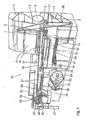
- Fig. 1 shows a perspective view of a single-strand cigarette rod machine 50, ie a stranding machine for processing tobacco fibers to a tobacco fiber strand for the production of cigarettes.
- the cigarette rod making machine 50 serves as an exemplary embodiment of a machine in which a device according to the invention can be used.
- the devices 100, 200, 300 according to the invention shown are designed to be used for cigarette rod machines with two fiber strands.
- each double-existing components can also be easily used and in a single-strand cigarette rod machine 50 as in Fig. 1 shown can be used.
- a trimmer 19 removes excess tobacco from the tobacco rod, which is then placed on a synchronized cigarette paper strip 21.
- the cigarette paper strip 21 is withdrawn from a reel 22, passed through a printing unit 23 and placed on a driven format tape 24.
- the format strip 24 transports the tobacco rod and the cigarette paper strip 21 through a format 26, in which the cigarette paper strip 21 is folded around the tobacco rod, so that still protrudes an edge which is glued in a known manner by a Glimapparat, not shown. Then the bond is closed and dried by a Tandemnahtplätte 27.
- a thus formed cigarette rod 28 passes through a strand density meter 29, which controls the device 19, and is cut by a knife apparatus 31 into double-length cigarettes 32.
- the double-ended cigarettes 32 are transferred from a controlled arms 33 having Mattergabevorriuchtung 34 a transfer drum 36 of a filter attachment machine 37, on the cutting drum 38, they are shared with a circular knife in single cigarettes.
- Conveyor belts 39, 41 promote excess tobacco in a arranged under the reservoir 4 container 42, from which the recycled tobacco is removed from the vertical conveyor 5 again.
- the inventive devices 100, 200, 300, 400 shown are designed to be used for cigarette rod machines with two fiber strands. These are in each case the components 111, 113, 115, 117, 121, 122, 131, 132, 141, 151, 152, 155, 156, 212, 213, 215, 217 required for a device according to the invention for a cigarette rod machine with only one fiber strand , 221, 222, 231, 232, 241, 251, 252, 255, 256, 311, 313, 315, 317, 321, 322, 331, 332, 341, 351, 352, 355, 356, 411, 413, 415 , 417, 421, 422, 431, 432, 441, 451, 452, 455, 456 a second time 112, 114, 116, 118, 123, 124, 133, 134, 142, 153, 154, 157, 158, 212 , 214, 216, 218, 223,
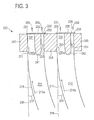
- illustrated first embodiment of the device 100 comprises two strand guide channels 111, 112 each having a first portion 131, 133 for shaking the strand and a respective second section 132, 134 for sucking excess air.
- the first two sections 131, 133 of the strand guide channels 111, 112 are on the suction side of the respective first suction belts 121, 123 limited.
- the respective second sections 132, 134 of the strand guide channels 111, 112 are each bounded by a second suction belt 122, 124.
- a web 141, 142 is arranged in each case, which extends to the suction belt.
- the suction band-side end of the strand guide channels 111, 112, on which the respective first 131, 133 and second 132, 134 sections are arranged, are held by holding sections 143, 144, 145 of a holding device.
- the strand guide channels 111, 112 each have an opening into the strand guide channel guide wall 113, 114, which is opposite to the vertical 115, 116 provided with a preferably variable curvature. This curvature is in FIG. 2 represented by increasing with increasing distance from the intake-side end of the strand guide channels 111, 112 increasing angle 117, 118.
- the material to be screened is subject to centrifugal forces which concentrate the material to be screened along the guide forces 113, 114 and lead the material to be screened along the arrows 113a, 114a predominantly into the respective first sections 131, 133 of the strand guide channels 111, 112 , In this way, the first sections 131, 133 predominantly flow through a mixture of material to be scoured and air in the direction of the arrows 151, 153.
- the respectively second sections 132, 134 of the strand guide channels 111, 112 are predominantly replaced by excess air in the direction of the arrows 152, Flows through 154.
- the first 131, 133 and second 132, 134 sections of the strand guide channels 111, 112, viewed in the conveying direction of the suction strand conveyor, are arranged laterally side by side and substantially parallel to one another.
- the flow or suction direction of the mixture of material profundschauerndem and air 151, 153 and the flow or suction direction of excess air 152, 154 are preferably substantially parallel.
- the suction device constructed a suction pressure and the excess air from the respective second portions 132, 134 sucked through the air-permeable second suction belts 122, 124 in the direction of the arrows 156, 158.
- the second sections 132, 134 is predominantly excess air. Nevertheless, material to be screened in the second sections 132, 134 remains on the sides of the second suction belts 122, 124 facing the strand guide channels 111, 112 in the respective second sections 132, 134.
- the two first suction belts 121, 123 with respect to the second suction belts 122, 124 have different materials, structures, surfaces and / or tissue pore sizes.
- first suction belts 121, 123 are operated in the conveying direction of the suction belt conveyor, whereas the second suction belts 122, 124 are counter to this direction, i. against the conveying direction of the Saugstrang makeupers, operated.
- second suction belts 122, 124 are counter to this direction, i. against the conveying direction of the Saugstrangenseers, operated.
- there is an advantageous self-cleaning effect of the second suction belts 122, 124 since they are operated in opposite directions to the increasing strand structure and thus also increasing density of legislativeschauernden material in opposite directions.
- an advantageous throttle effect results from the opposite direction of the second suction belts 122, 124.
- suction or suction directions on the side facing the strand guide channels 111, 112 side of the suction belts 121, 122, 123, 124 in the direction of the arrows 155, 156, 157, 158 are preferably substantially parallel.
- the respective first intake pressure in the direction of the arrows 155, 157 is preferably greater than the respectively second intake pressure in the direction of the arrows 156, 158.
- suction shafts 161, 162, 163, 164 are arranged, which are connected to suction sources of a suction device (not shown) in connection.
- the respective first sections 131, 133 communicate with the first two suction ducts 161, 163 via the air-permeable first suction belts 121, 123.
- a respective first suction pressure is formed by a suction device.
- the respective first suction shafts 161, 163 may be connected to one another and have a common first suction source or two separate first suction sources.
- the respective second sections 132, 134 communicate with the second suction ducts 162, 164 via the air-permeable second suction belts 122, 124.
- the suction device forms in the second suction wells 162, 164 each a second suction pressure.
- the second suction wells 162, 164 may be separated from one another by a dividing wall 165 or connected to each other without the dividing wall 165 and having a common second suction source or two separate second suction sources.
- the first suction pressure formed in the first suction wells 161, 163 is preferably higher than the second suction pressure formed in the second suction wells 162, 164.
- suction pressure is meant a negative pressure, i. a higher negative pressure corresponds to a lower absolute pressure.
- FIG. 5 shown first embodiment of the device according to the invention. Parts in the Figures 3 . 4 and 6 across from FIG. 2 are unchanged will not be described again.
- the same or substantially functionally identical parts are in FIG. 3 with opposite FIG. 2 at 100, in FIG. 4 with opposite FIG. 2 at 200, in FIG. 6 with opposite FIG. 2 marked by 300 increased reference numerals.
- the following Description is particularly directed to the differences of the second, third and fourth embodiments from the first embodiment.
- the second, third and fourth embodiments can be used with the in FIG. 5 shown suction wells 161, 162, 163, 164 and optionally the partition 165 are combined.
- the first 221, 223 and second 222, 224 suction belt are integrally formed as a suction belt 225, 226. It is particularly preferred that the two one-piece suction belts 225, 226 each have different materials, structures, surfaces and or tissue pore sizes in the areas of the respective first suction belt 221, 223 and the respective second suction belt 222, 224 have. In this way, the advantages of the one-piece design, namely in particular a simple construction and a common drive, can be combined with the advantages of different Saugbandeigenschaften.
- the one-piece suction belt 327 has at least four different sections corresponding to the four suction belts 321, 322, 323, 324, and the various properties, in particular different materials, structures, surfaces and / or tissue pore sizes have.
- the portions corresponding to the two first suction bands 321, 323 have different properties than the portions corresponding to the respective second suction bands 322, 324.
- strand guide channels 411 and 412 are arranged mirror images of each other.
- the first sections 431, 433 for shunting the strands with the variably curved guide walls 413, 414 are arranged directly adjacent to each other, while the second sections 452, 454 for sucking excess air are arranged on the outside.
- the curvature of the guide walls 413, 414 is opposite to each other.
- the first sections 431, 433 are all direct arranged adjacent to each other. This construction allows a more compact design of the device according to the invention.
Abstract
Description
Die Erfindung betrifft eine Vorrichtung zum Herstellen mindestens eines Stranges der tabakverarbeitenden Industrie, mit mindestens einem Strangführungskanal und mindestens einem mindestens ein Saugband aufweisenden Saugstrangförderer.The invention relates to a device for producing at least one strand of the tobacco-processing industry, with at least one strand guide channel and at least one at least one suction belt suction conveyor.
Ein weiterer Aspekt der Erfindung betrifft ein Verfahren zum Herstellen mindestens eines Stranges der tabakverarbeitenden Industrie.Another aspect of the invention relates to a method for producing at least one strand of the tobacco processing industry.
Eine Vorrichtung der eingangs genannten Art ist aus der
Dies wird in der
Eine weitere Vorrichtung zum Transportieren und Behandeln von Tabakpartikeln zeigt
Die
Die in
Es ist daher die Aufgabe der vorliegenden Erfindung, eine verbesserte Vorrichtung und ein verbessertes Verfahren zum Herstellen mindestens eines Stranges der tabakverarbeitenden Industrie bereit zu stellen, die bzw. das einen oder mehrere der genannten Verbesserungsbedarfe erfüllt.It is therefore the object of the present invention to provide an improved apparatus and an improved method for producing at least one strand of the tobacco processing industry that meets one or more of said improvement requirements.
Diese Aufgabe wird erfüllt durch eine Vorrichtung der eingangs genannten Art, die dadurch gekennzeichnet ist, dass der Strangführungskanal einen ersten Abschnitt zum Aufschauern des Stranges und einen zweiten Abschnitt zum Absaugen überschüssiger Luft aufweist, wobei der erste und der zweite Abschnitt mindestens saugbandseitig von dem mindestens einen Saugband begrenzt werden.This object is achieved by a device of the type mentioned, which is characterized in that the strand guide channel has a first section for churning the strand and a second section for sucking excess air, wherein the first and the second section at least on the intake manifold side of the at least one Suction belt to be limited.
Der Stand der Technik wird dank der vorliegenden Erfindung insbesondere hinsichtlich der Konstruktion der Vorrichtung weiter verbessert, denn die vorliegende Erfindung reduziert den Tabakverlust, vermindert Behinderungen im Tabakfluss, wie insbesondere Verstopfungen enger Kanäle, reduziert den Reinigungsaufwand und stellt vor allem auch eine einfach und effizient zu realisierende Konstruktion bereit.The prior art is further improved thanks to the present invention, in particular with regard to the construction of the device, because the present invention reduces tobacco loss, reduces obstructions in the tobacco flow, in particular obstruction narrow channels, reduces the cleaning effort and above all, a simple and efficient too realizing construction ready.
Die erfindungsgemäße Vorrichtung eignet sich gleichermaßen zum Herstellen nur eines Stranges der tabakverarbeitenden Industrie, insbesondere eines Tabakstranges zur Herstellung von Zigaretten oder auch eines oder mehrerer Stränge zur Herstellung von Filtern, wie die für die Herstellung von zwei oder mehrerer solcher Stränge. Im Falle der Herstellung von zwei oder mehreren solcher Stränge sind die entsprechenden Elemente der Vorrichtung, wie Strangführungskanal und Saugband, ebenfalls in entsprechend erhöhter Anzahl vorzusehen. Sofern sich in dieser Beschreibung Ausführungen auf die Herstellung von nur einem Strang beziehen, sind diese gleichermaßen auf Vorrichtungen zum Herstellen von zwei oder mehr Strängen übertragbar.The device according to the invention is equally suitable for producing only one strand of the tobacco-processing industry, in particular a tobacco rod for Production of cigarettes or even one or more strands for the production of filters, such as those for the production of two or more such strands. In the case of the production of two or more such strands, the corresponding elements of the device, such as strand guide channel and suction belt, are also provided in accordance with an increased number. Insofar as in this description embodiments refer to the production of only one strand, these are equally applicable to devices for producing two or more strands.
Die erfindungsgemäße Ausbildung von zwei verschiedenen Abschnitten, oder auch sogenannten Segmenten, des Strangführungskanals einerseits zum Aufschauern des Stranges und andererseits zum Absaugen überschüssiger Luft zeichnet sich dadurch aus, dass beide Abschnitte bis an das mindestens eine Saugband reichen.The inventive design of two different sections, or so-called segments, of the strand guide channel on the one hand for shaking the strand and on the other hand for sucking excess air is characterized in that both sections extend to the at least one suction belt.
Die erfindungsgemäße Anordnung ermöglicht es, dass das Absaugen überschüssiger Luft ebenso wie das Aufschauern des Stranges in unmittelbarer Nähe des mindestens einen Saugbands erfolgt. Demgegenüber sehen die im Stand der Technik existierenden Lösungen vor, die überschüssige Luft in einem in einer von dem Saugband wegführenden Richtung größeren Abstand vom Saugband abzusaugen. Der Erfindung liegt dabei die Erkenntnis zugrunde, dass ein möglichst spätes Absaugen der überschüssigen Luft, d.h. ein Absaugen in dem von dem mindestens einen Saugband begrenzten zweiten Abschnitt, zu einer Verringerung des Tabakverlustes einerseits und zu einem verbesserten, homogeneren Strangaufbau andererseits führt.The inventive arrangement makes it possible that the suction of excess air as well as the churning of the strand takes place in the immediate vicinity of the at least one suction belt. In contrast, existing in the prior art solutions to suck the excess air in a direction away from the suction belt direction greater distance from the suction belt. The invention is based on the finding that as late as possible extraction of the excess air, i. suction in the second section delimited by the at least one suction belt leads to a reduction in tobacco loss on the one hand and to an improved, more homogeneous strand structure on the other hand.
Ein weiterer Vorteil der erfindungsgemäßen Vorrichtung liegt darin, dass insbesondere im zweiten Abschnitt mögliche Verstopfungen oder Behinderungen im Luftstrom deutlich reduziert werden können, da sich durch die erfindungsgemäßen Anordnung der beiden Abschnitte und insbesondere durch die erst in unmittelbarer Nähe zu dem mindestens einen Saugband erfolgende Absaugung überschüssiger Luft im zweiten Abschnitt weniger aufzuschauerndes Material, insbesondere Tabak und ggf. Zusatzstoffe, befindet, das sich im zweiten Abschnitt ablagern und so zu Beeinträchtigungen des Luftstroms, insbesondere Verstopfungen, führen könnte. Wenn sich im zweiten Abschnitt weniger aufzuschauerndes Material befindet, können auch die Verluste, insbesondere Tabakverluste, bedingt durch ungewolltes Absaugen von aufzuschauerndem Material im zweiten Abschnitt in vorteilhafter Weise deutlich reduziert werden.Another advantage of the device according to the invention is that, in particular in the second section, possible blockages or obstructions in the air flow can be significantly reduced, since the inventive arrangement of the two sections and in particular by the suction taking place only in immediate proximity to the at least one suction belt Air in the second section less aufzuschauernendes material, especially tobacco and possibly additives, is located, which could be deposited in the second section and so could affect the flow of air, especially blockages lead. If less aufzuschauernendes material in the second section, the losses, in particular tobacco losses, due to unwanted suction of Aufzuschauerndem material in the second section can be significantly reduced in an advantageous manner.
Weiterhin sind die genannten Vorteile mit der erfindungsgemäßen Anordnung der Bestandteile der Vorrichtung in einer besonders einfachen sowie leicht zu reinigenden und zu wartenden Konstruktion zu realisieren.Furthermore, the advantages mentioned are to be realized with the inventive arrangement of the components of the device in a particularly simple and easy to clean and maintain construction.
Vorzugsweise enden beide Abschnitte des Strangführungskanals in Höhe des mindestens einen Saugbands. Weiterhin vorzugsweise erstrecken sich der erste und zweite Abschnitt sowohl in einer von dem mindestens einen Saugband wegführenden Richtung entlang des Strangführungskanals als auch in einer zu dem mindestens einen Saugband bzw. der Förderrichtung parallelen Richtung entlang des mindestens einen Saugbands, vorzugsweise über die gesamte Länge des Aufschüttbereichs.Preferably, both sections of the strand guide channel end at the height of the at least one suction belt. Furthermore, the first and second sections preferably extend along the strand guide channel both in a direction away from the at least one suction belt and in a direction parallel to the at least one suction belt or conveying direction along the at least one suction belt, preferably over the entire length of the landfill region ,
Die Erfindung kann dadurch fortgebildet werden, dass der erste und der zweite Abschnitt des Strangführungskanals in Förderrichtung des Saugstrangförderers gesehen lateral nebeneinander angeordnet sind. Diese bevorzugte Anordnung der beiden Abschnitte entspricht im Wesentlichen einer Aufteilung des Strangführungskanals parallel zur Förderrichtung des Saugstrangförderers in mindestens den ersten und den zweiten Abschnitt. Mit dieser erfindungsgemäßen Anordnung kann in besonders bevorzugter Weise eine Erstreckung der beiden Abschnitte in Förderrichtung entlang des Strangführungskanals erreicht werden.The invention can be developed by arranging the first and second sections of the strand guide channel laterally next to one another, as seen in the conveying direction of the suction strand conveyor. This preferred arrangement of the two sections essentially corresponds to a division of the strand guide channel parallel to the conveying direction of the suction strand conveyor in at least the first and the second section. With this arrangement according to the invention, an extension of the two sections in the conveying direction along the strand guide channel can be achieved in a particularly preferred manner.
Die Erfindung kann dadurch fortgebildet werden, dass der erste und der zweite Abschnitt des Strangführungskanals in Förderrichtung des Saugstrangförderers im Wesentlichen parallel zueinander angeordnet sind. Diese bevorzugte erfindungsgemäße Anordnung der beiden Abschnitte stellt eine besonders einfache und effiziente Konstruktion der erfindungsgemäßen Vorrichtung dar.The invention can be developed by arranging the first and second sections of the strand guide channel substantially parallel to one another in the conveying direction of the suction strand conveyor. This preferred arrangement according to the invention of the two sections represents a particularly simple and efficient construction of the device according to the invention.
Die Erfindung kann dadurch fortgebildet werden, dass der erste Abschnitt überwiegend von einem Gemisch aus aufzuschauerndem Material und Luft, insbesondere einem Tabak-Luft-Gemisch, und der zweite Abschnitt überwiegend von überschüssiger Luft durchströmt wird. Diese bevorzugte Fortbildungsform sieht vor, dass die beiden Abschnitte derart angeordnet sind, dass das Gemisch aus aufzuschauerndem Material und Luft überwiegend den ersten Abschnitt durchströmt und durch den zweiten Abschnitt überwiegend überschüssige Luft strömt, die gegenüber den existierenden Lösungen im Stand der Technik nur wenig aufzuschauerndes Material enthält. Auf diese Weise kann der Verlust an aufzuschauerndem Material, insbesondere der Tabakverlust, deutlich reduziert werden, da die aus dem zweiten Abschnitt abgesaugte überschüssige Luft nur wenig aufzuschauerndes Material enthält.The invention can be developed by the fact that the first section is predominantly flowed through by a mixture of aufzuschauerndem material and air, in particular a tobacco-air mixture, and the second section predominantly of excess air. This preferred embodiment provides that the two sections are arranged so that the mixture of aufzuschauerndem material and air predominantly flows through the first section and flows through the second section predominantly excess air, compared to the existing solutions in the prior art only little aufzuschauernendes material contains. In this way, the loss of aufzuschauerndem material, in particular the tobacco loss can be significantly reduced because the extracted from the second section excess air contains little aufzuschauernendes material.
Weiterhin kann durch diese bevorzugte Fortbildungsform ein Verstopfen des zweiten Abschnittes, der in der Regel einen kleineren Querschnitt aufweist als der erste Abschnitt, reduziert werden, da sich im zweiten Abschnitt nur ein sehr kleiner Teil aufzuschauerndes Material befindet, das sich ablagern und so zu Behinderungen, wie Verstopfungen des Strangführungskanals führen könnte.Furthermore, this preferred embodiment can reduce clogging of the second section, which usually has a smaller cross-section than the first section, since only a very small portion of the material to be screened is in the second section, which deposits and thus leads to disabilities, as could cause blockages of the strand guide channel.
Die Erfindung kann dadurch fortgebildet werden, dass der erste und der zweite Abschnitt des Strangführungskanals durch einen, bevorzugt bis zum Saugstrangförderer reichenden, Steg voneinander getrennt sind.The invention can be developed by the fact that the first and the second section of the strand guide channel are separated from one another by a web, preferably extending to the suction strand conveyor.
Die bevorzugte Trennung der beiden Abschnitte des Strangführungskanals durch einen Steg verstärkt die zuvor beschriebenen Vorteile, da durch den Steg ein Vermischen der überschüssigen Luft mit aufzuschauerndem Material zusätzlich verhindert wird, so dass mögliche Verluste an aufzuschauerndem Material weiter reduziert werden können. Weiterhin kann der Strangaufbau im ersten Abschnitt durch die Ausbildung eines Stegs weiter verbessert werden, da der Steg eine Beeinträchtigung der Ausbildung des Stranges durch die Absaugung überschüssiger Luft verhindert oder zumindest verringert.The preferred separation of the two sections of the strand guide channel by a web reinforces the advantages described above, since the web is additionally prevented from mixing the excess air with the material to be screened, so that possible losses of material to be screened can be further reduced. Furthermore, the strand structure in the first section can be further improved by the formation of a web, since the web prevents or at least reduces impairment of the formation of the strand by the extraction of excess air.
Es ist weiterhin bevorzugt, dass die erfindungsgemäße Vorrichtung eine Saugvorrichtung aufweist, die ausgebildet ist, einen Ansaugdruck auszubilden zum Aufschauern des Stranges und zum Absaugen überschüssiger Luft. Unter Ansaugdruck wird hinsichtlich der vorliegenden Erfindung ein Unterdruck verstanden, der durch das mindestens eine Saugband hindurch das Gemisch aus aufzuschauerndem Material und Luft bzw. die überschüssige Luft ansaugt. Je höher der Ansaugdruck ist, desto größer ist der Unterdruck, d. h. desto niedriger ist der absolute Wert des Druckes. Ein niedrigerer Ansaugdruck bzw. Unterdruck entspricht demnach einen höheren absoluten Druck.It is further preferred that the device according to the invention has a suction device, which is designed to form a suction pressure for churning the strand and for sucking off excess air. Under suction pressure is understood in terms of the present invention, a negative pressure, which sucks through the at least one suction belt through the mixture of aufzuschauerndem material and air or the excess air. The higher the suction pressure, the greater the negative pressure, d. H. the lower is the absolute value of the pressure. A lower suction pressure or vacuum accordingly corresponds to a higher absolute pressure.
Die erfindungsgemäße Vorrichtung wird vorzugsweise durch eine Saugvorrichtung fortgebildet, die eine erste und eine zweite Saugquelle aufweist, wobei die erste Saugquelle über einen ersten Saugschacht und das mindestens eine Saugband mit dem ersten Abschnitt des Strangführungskanals und die zweite Saugquelle über einen zweiten Saugschacht und das mindestens eine Saugband mit dem zweiten Abschnitt des Strangführungskanals in Verbindung steht.The device according to the invention is preferably developed by a suction device having a first and a second suction source, wherein the first suction source via a first suction chute and the at least one suction belt with the first portion of the strand guide channel and the second suction source via a second suction chute and the at least one Suction belt is in communication with the second section of the strand guide channel.
Erfindungsgemäß ist es besonders bevorzugt, die beiden Abschnitte mit getrennten Saugquellen zu verbinden, so dass sich zwei getrennte Strömungen ausbilden können: Vom ersten Abschnitt durch das mindestens eine Saugband und durch den ersten Saugschacht zur ersten Saugquelle und vom zweiten Abschnitt durch das mindestens eine Saugband über den zweiten Saugschacht zur zweiten Saugquelle. Dabei ist weiterhin insbesondere bevorzugt, dass diese beiden Ströme mindestens abschnittsweise im Wesentlichen parallel verlaufen, insbesondere in der Zone des Strangführungskanals, in der sich der Strang bildet, und in der unmittelbaren Umgebung des mindestens einen Saugbands. Auf diese Weise bildet sich eine vorteilhafte Luftströmung aus, die eine Trennung des Gemischs aus aufzuschauerndem Material und Luft einerseits sowie der überschüssigen Luft andererseits erleichtert. Weiterhin führt eine solche Anordnung dazu, dass der Strangaufbau im ersten Abschnitt des Stromführungskanals nicht durch eine seitlich abzweigende Überschussluftabsaugung beeinträchtigt wird.According to the invention, it is particularly preferred to connect the two sections with separate suction sources, so that two separate flows can form: from the first section through the at least one suction belt and through the first suction shaft to the first suction source and from the second portion through the at least one suction belt via the second suction chute to the second suction source. In this case, it is furthermore particularly preferred that these two streams run essentially parallel at least in sections, in particular in the zone of the strand guide channel in which the strand forms, and in the immediate vicinity of the at least one suction belt. In this way, an advantageous air flow is formed, which facilitates the separation of the mixture of aufzuschauerndem material and air on the one hand and the excess air on the other. Furthermore, such an arrangement results in that the strand construction in the first section of the flow guide channel is not affected by a laterally branching excess air suction.
Für den Fall, dass eine Vorrichtung zum Herstellen von zwei oder mehreren Strängen der tabakverarbeitenden Industrie vorgesehen ist und die entsprechenden Komponenten der Vorrichtung daher zwei- oder mehrfach vorgesehen sind, können die den jeweils ersten Abschnitten zugeordneten ersten Saugschächte miteinander verbunden sein und/oder die jeweils zweiten Saugschächte die den jeweiligen zweiten Abschnitten zugeordnet sind, ebenfalls miteinander verbunden sein.In the event that a device for producing two or more strands of the tobacco processing industry is provided and the corresponding components of the device are therefore provided two or more times, the first suction sections associated with the respective first sections can be connected to each other and / or each second suction wells which are associated with the respective second sections, also be connected to each other.
Die Erfindung wird bevorzugt dadurch fortgebildet, dass mindestens eine der Saugquellen ausgebildet ist, einen von dem Ansaugdruck der jeweils anderen Saugquelle unterschiedlichen Ansaugdruck auszubilden, wobei vorzugsweise der Ansaugdruck der ersten Saugquelle höher ist als der Ansaugdruck der zweiten Saugquelle.The invention is preferably developed in that at least one of the suction sources is designed to form a different from the suction pressure of the other suction source suction pressure, wherein preferably the suction pressure of the first suction source is higher than the suction pressure of the second suction source.
Durch die erfindungsgemäße Fortbildung kann der Ansaugdruck, dem die beiden Abschnitte des Strangführungskanals ausgesetzt sind, unterschiedlich ausgebildet werden. Dies trägt in vorteilhafter Weise dazu bei, dass die Strömung des Gemischs aus aufzuschauerndem Material und Luft einerseits sowie der überschüssigen Luft andererseits derart gesteuert werden kann, dass einerseits ein verbesserter, insbesondere homogener, Strangaufbau erreicht werden kann und gleichzeitig der Anteil an aufzuschauerndem Material im zweiten Abschnitt reduziert werden kann. Der dort in geringer Menge anfallende Tabak kann dem Verarbeitungsprozess wieder zugeführt werden. Dadurch, dass der Ansaugdruck der ersten Saugquelle vorzugsweise höher ist als der Ansaugdruck der zweiten Saugquelle, kann sichergestellt werden, dass das aufzuschauernde Material überwiegend im ersten Abschnitt zum Aufschauern des Stranges angesaugt wird und im zweiten Abschnitt überwiegend lediglich überschüssige Luft angesaugt wird.By means of the further development of the invention, the suction pressure to which the two sections of the strand guide channel are exposed can be formed differently. This contributes advantageously to the fact that the flow of the mixture of aufzuschauerndem material and air on the one hand and the excess air on the other hand can be controlled so that on the one hand an improved, in particular homogeneous, strand structure can be achieved and at the same time the amount aufzuschauerndem material in the second Section can be reduced. The there incurred in small quantities tobacco can be recycled to the processing process. The fact that the suction pressure of the first suction source is preferably higher than the suction pressure of the second suction source, it can be ensured that the aufzuschauernde material is sucked predominantly in the first section to churn the strand and in the second section predominantly only excess air is sucked.
Die Erfindung kann dadurch fortgebildet werden, dass die Saugvorrichtung ausgebildet ist, stromabwärts in Förderrichtung des Saugstrangförderers einen höheren Ansaugdruck auszubilden, wozu die Saugvorrichtung vorzugsweise mindestens eine weitere, stromabwärts in Förderrichtung des Saugstrangförderers angeordnete Saugquelle aufweist. Neben der zuvor beschriebenen Variation des Ansaugdrucks quer zur Förderrichtung des Saugstrangförderers ist weiterhin eine Variation des Ansaugdrucks entlang der Förderrichtung des Saugstrangförderers bevorzugt. Insbesondere ist eine solche unterschiedliche Ausbildung des Ansaugdrucks entlang der Förderrichtung des Saugstrangförderers für den ersten Abschnitt des Strangführungskanals bevorzugt, da entlang der Förderrichtung die Menge des an dem mindestens einen Saugband zu einem Strang aufgeschauerten Materials zunimmt und ein in dieser Richtung ebenfalls zunehmender Ansaugdruck die Strangbildung positiv beeinflussen kann. Vorzugsweise sind dazu eine, zwei oder mehrere zusätzliche Saugquellen entlang der Förderrichtung des Saugstrangförderers angeordnet, die über einen gemeinsamen oder zwei oder mehrere getrennte Saugschächte mit dem ersten Abschnitt des Strangführungskanals über das mindestens eine Saugband in Verbindung stehen. Diese zusätzlichen Saugquellen sind vorzugsweise ausgebildet, mit verschiedenen Ansaugdrücken betrieben werden zu können, so dass der Ansaugdruck entlang der Förderrichtung den Erfordernissen entsprechend variiert werden kann.The invention can be further developed in that the suction device is designed to form a higher suction pressure downstream in the conveying direction of the suction strand conveyor, for which purpose the suction device preferably has at least one further suction source arranged downstream in the conveying direction of the suction strand conveyor. In addition to the previously described variation of the suction pressure transversely to the conveying direction of the suction strand conveyor, a variation of the suction pressure along the conveying direction of the suction strand conveyor is furthermore preferred. In particular, such a different design of the suction pressure along the conveying direction of the Saugstrangförderers for the first portion of the strand guide channel is preferred because along the conveying direction increases the amount of the at least one suction belt aufauerten stranded material at the at least one suction and in this direction also increasing suction pressure strand formation positive can influence. For this purpose, one, two or more additional suction sources are preferably arranged along the conveying direction of the suction-strand conveyor, which are connected via a common or two or more separate suction ducts to the first section of the strand-guiding channel via the at least one suction belt. These additional suction sources are preferably designed to be operated with different suction pressures, so that the suction pressure along the conveying direction can be varied according to the requirements.
Die Erfindung kann durch ein Umluftsystem fortgebildet werden, das ausgebildet ist, die durch die Saugvorrichtung abgesaugte Luft dem Strangführungskanal wieder zuzuführen. Die durch die eine, zwei, und/oder mehrere weitere Saugquelle/n der Saugvorrichtung angesaugte Luft wird vorzugsweise gereinigt bzw. gefiltert und anschließend dem Strangführungskanal für ein erneutes An- bzw. Absaugen wieder zugeführt. Ein derartiges Umluftsystem ist bevorzugt, um das Bereitstellen von Frischluft sowie das Abführen von Abluft aus dem System zu reduzieren.The invention can be developed by a recirculation system, which is designed to supply the extracted by the suction device air to the strand guide channel again. The air sucked in by the one, two, and / or several further suction source (s) of the suction device is preferably cleaned or filtered and subsequently returned to the strand guide channel for renewed suction or suction. Such a recirculation system is preferred to reduce the supply of fresh air and the removal of exhaust air from the system.
Die Erfindung kann dadurch fortgebildet werden, dass der Saugstrangförderer ein erstes Saugband zum Aufschauern des Stranges und ein zweites Saugband zum Absaugen überschüssiger Luft aufweist, wobei das zweite Saugband vorzugsweise ein anderes Material, eine andere Struktur und/oder eine andere Oberfläche, insbesondere eine andere Gewebeporengröße, aufweist als das erste Saugband. Diese Fortbildungsform sieht zwei Saugbänder mit unterschiedlichen Funktionen - ein erstes Saugband zum Aufschauern des Stranges und ein zweites Saugband zum Absaugen überschüssiger Luft mit vorzugsweise unterschiedlichen Eigenschaften vor. Das Aufschauern des Stranges bzw. das Absaugen überschüssiger Luft erfolgt durch das Ansaugen durch das erste bzw. zweite Saugband. Indem die beiden Saugbänder unterschiedliche Eigenschaften aufweisen, die insbesondere zu einer unterschiedlichen Luftdurchlässigkeit der beiden Saugbändern führen können, kann auf diese Weise das Ansaugverhalten positiv beeinflusst und gesteuert werden. Dabei ist es insbesondere bevorzugt, die Eigenschaften der Saugbänder beispielsweise auf den Querschnitt des zugehörigen Abschnitts des Strangführungskanals, den Ansaugdruck der zugehörigen Saugquelle/n und/oder Art und/oder Menge des aufzuschauernden Materials auszurichten.The invention may be further developed in that the suction belt conveyor has a first suction belt for churning the strand and a second suction belt for sucking off excess air, wherein the second suction belt is preferably a different material, a different structure and / or a different surface, in particular a different fabric pore size , as the first suction belt. This further development form provides two suction belts with different functions - a first suction belt for shaking the strand and a second suction belt for suctioning off excess air with preferably different properties. The churning of the strand or the extraction of excess air takes place by the suction through the first or second suction belt. By the two suction belts having different properties, which may in particular lead to a different air permeability of the two suction belts, the intake behavior can be positively influenced and controlled in this way. In this case, it is particularly preferred to align the properties of the suction belts, for example, with the cross-section of the associated section of the strand guide channel, the suction pressure of the associated suction source (s) and / or the type and / or quantity of the material to be screened.
Die Erfindung kann dadurch fortgebildet werden, dass das erste und das zweite Saugband parallel zueinander auf einer Ebene angeordnet sind. Die Anordnung der beiden Saugbänder in gleicher Höhe stellt eine besonders effiziente und einfach zu realisierende Konstruktion der erfindungsgemäßen Vorrichtung dar und kann in positiver Weise den Strangaufbau beeinflussen.The invention can be developed by arranging the first and second suction belts parallel to one another on a plane. The arrangement of the two suction belts at the same height represents a particularly efficient and easy-to-implement construction of the device according to the invention and can positively influence the strand structure.
Weiterhin sind Querschnittsveränderungen der Saugbänder und/oder Querschnittsveränderungen der Saugschächte bevorzugt, die eine vorteilhafte Drosselwirkung bewirken können.Furthermore, cross-sectional changes of the suction belts and / or changes in cross section of the suction ducts are preferred, which can bring about an advantageous throttling effect.
Die Erfindung kann durch eine Reinigungsvorrichtung zum, vorzugsweise kontinuierlichen, Reinigen mindestens eines, vorzugsweise des zweiten, Saugbands fortgebildet werden. Das zweite Saugband dient dem Absaugen überschüssiger Luft, so dass die Ablagerung von aufzuschauerndem Material oder Verunreinigungen am zweiten Saugband unerwünscht ist, da dies die Saugleistung beeinträchtigen kann. Es ist daher bevorzugt, dass insbesondere das zweite Saugband während des Betriebs der Vorrichtung gereinigt wird. Eine besonders einfach zu realisierende und bevorzugte Reinigung kann durch kontinuierliches Reinigen des zweiten Saugbandes durch Abschaben mittels eines Schabers erzielt werden. Auf diese Weise kann sichergestellt werden, dass die Saugleistung zum Absaugen überschüssiger Luft im Wesentlichen den gewünschten Wert beibehält und somit keine Beeinträchtigungen des Strangaufbaus und/oder der Absaugung überschüssiger Luft durch Schwankungen in der Ansaugleistung durch am Saugband abgelagertes Material auftreten.The invention can be developed by a cleaning device for, preferably continuous, cleaning at least one, preferably the second, suction belt. The second suction belt is used to extract excess air, so that the deposition of aufzuschauerndem material or impurities on the second suction belt is undesirable, as this may affect the suction performance. It is therefore preferred that in particular the second suction belt is cleaned during the operation of the device. A particularly easy to implement and preferred cleaning can be achieved by continuously cleaning the second suction belt by scraping with a scraper. In this way it can be ensured that the suction power for extracting excess air substantially maintains the desired value and thus no adverse effects on the strand structure and / or the extraction of excess air due to fluctuations in the suction through deposited material on the suction belt.
Die Erfindung kann dadurch fortgebildet werden, dass das erste Saugband ausgebildet ist, in Förderrichtung des Saugstrangförderers betrieben zu werden, und das zweite Saugband ausgebildet ist, entgegen der Förderrichtung des Saugstrangförderers betrieben zu werden. Das Vorsehen von zwei getrennten Saugbändern ermöglicht es in vorteilhafter Weise, die beiden Saugbänder gegenläufig zueinander zu betreiben zu können. Das erste Saugband, an dem der Strang aufgeschauert wird, wird dabei in Förderrichtung des Saugstrangförderers betrieben. Es ist besonders bevorzugt, das zweite Saugband hingegen in entgegengesetzter Richtung zu betreiben. Dies hat den Vorteil, dass am Ende des Strangführungskanals, an dem der Strang zunehmend aufgeschauert ist, auf diese Weise das zweite Saugband erst in den Strangführungskanal eintritt und diesen in zum ersten Saugband entgegengesetzten Richtung durchläuft. Auf diese Weise kann eine Art Selbstreinigung des zweiten Saugbands erfolgen, da die Belastung des zweiten Saugbands mit gegebenenfalls in den zweiten Abschnitt gelangtem aufzuschauerndem Material entgegen der Förderrichtung des Saugstrangförderers abnimmt. Weiterhin kann auf diese Weise eine vorteilhafte Drosselwirkung erzielt werden.The invention can be further developed in that the first suction belt is designed to be operated in the conveying direction of the suction belt conveyor, and the second suction belt is designed to be operated counter to the conveying direction of the suction belt conveyor. The provision of two separate suction belts makes it possible in an advantageous manner to be able to operate the two suction belts in opposite directions to each other. The first suction belt, on which the strand is thrown up, is thereby operated in the conveying direction of the suction strand conveyor. It is particularly preferred, however, to operate the second suction belt in the opposite direction. This has the advantage that in this way the second suction belt only enters the strand guide channel at the end of the strand guide channel, on which the strand is increasingly hunched, and passes through this in the direction opposite to the first suction belt. In this way, a kind of self-cleaning of the second suction belt can take place, since the load on the second suction belt decreases with the material which has possibly reached the second section, against the conveying direction of the suction strand conveyor. Furthermore, an advantageous throttle effect can be achieved in this way.
Alternativ zur letztgenannten Fortbildung kann die Erfindung dadurch fortgebildet werden, dass das erste und das zweite Saugband einstückig ausgebildet sind. Bei einer Vorrichtung zum Herstellen von zwei oder mehr Strängen der tabakverarbeitenden Industrie können auch die weiteren jeweils ersten und zweiten Saugbänder jeweils einstückig ausgebildet sein. Es ist ebenfalls möglich, alle Saugbänder einer erfindungsgemäßen Vorrichtung einstückig auszubilden.As an alternative to the last-mentioned further development, the invention can be developed by integrally forming the first and second suction belts. In a device for producing two or more strands of the tobacco-processing industry, the other respective first and second suction belts may each be formed in one piece. It is also possible to form all suction belts of a device according to the invention in one piece.
Die einstückige Ausbildung von erstem und zweitem Saugband sowie gegebenenfalls weiteren Saugbändern hat den Vorteil einer besonders einfachen Konstruktion und ggf. eines gemeinsamen Antriebs der Saugbänder. Durch die Ausbildung der einzelnen Saugbänder als Abschnitte eines einstückig ausgebildeten Saugbands mit unterschiedlichen Eigenschaften, können einerseits die mit der einstückigen Ausbildung verbundenen Vorteile und gleichzeitig der Vorteil von verschiedenen Eigenschaften der einzelnen Saugbänder realisiert werden.The one-piece design of the first and second suction belt and optionally further suction belts has the advantage of a particularly simple construction and possibly a common drive of the suction belts. By forming the individual suction belts as sections of an integrally formed suction belt with different properties, on the one hand the advantages associated with the one-piece design and at the same time the advantage of different properties of the individual suction belts can be realized.
Die Erfindung kann dadurch fortgebildet werden, dass der Strangführungskanal eine, vorzugsweise variable, Krümmung aufweist, wobei die Krümmung vorzugsweise derart ausgebildet ist, dass aufzuschauerndes Material überwiegend in den ersten Abschnitt des Strangführungskanals geführt wird. Die erfindungsgemäße Krümmung des Strangführungskanals wirkt vorzugsweise mit der Strömung des Gemischs aus aufzuschauerndem Material und Luft bzw. der überschüssigen Luft zusammen, so dass die Ausbildung eines homogenen Stranges einerseits und die Abfuhr überschüssiger Luft andererseits möglichst optimal unterstützt werden. Dazu ist die Krümmung des Strangführungskanals vorzugsweise derart ausgebildet, dass auf das aufzuschauernde Material Fliehkräfte ausgeübt werden, die das Material in den ersten Abschnitt des Strangführungskanals lenken. Dazu ist weiterhin vorzugsweise eine mit einer, vorzugsweise variablen, Krümmung versehene, in den Strangführungskanal mündende Führungswand vorgesehen, an der das aufzuschauernde Material entlang geführt wird. Auf diese Weise kann die Trennung von Gemisch aus aufzuschauerndem Material und Luft einerseits und überschüssiger Luft andererseits verbessert werden, so dass auch ein möglicher Verlust an aufzuschauerndem Material weiter reduziert und der Strangaufbau weiter verbessert werden kann.The invention can be further developed in that the strand guide channel has a, preferably variable, curvature, wherein the curvature is preferably formed such that material to be screened is predominantly guided into the first section of the strand guide channel. The curvature of the strand guide channel according to the invention preferably interacts with the flow of the mixture of material and air aufzuschauerndem or excess air, so that the formation of a homogeneous strand on the one hand and the removal of excess air on the other hand are optimally supported. For this purpose, the curvature of the strand guide channel is preferably designed such that on the aufzuschauernde material centrifugal forces are exerted, which direct the material in the first section of the strand guide channel. For this purpose, one further preferably with a, preferably variable, curvature provided, opening into the strand guide channel guide wall provided on which the aufzuschauernde material is guided along. In this way, the separation of the mixture of aufzuschauerndem material and air on the one hand and excess air on the other hand can be improved, so that also a possible loss of aufzuschauerndem material further reduced and the strand structure can be further improved.
Weitere vorteilhafte Ausführungsvarianten der erfindungsgemäßen Vorrichtung ergeben sich durch Kombination der hier erörterten bevorzugten Merkmale.Further advantageous embodiments of the device according to the invention will become apparent by combining the preferred features discussed herein.
Ein weiterer Aspekt der Erfindung ist ein Verfahren zum Herstellen mindestens eines Stranges der tabakverarbeitenden Industrie der eingangs genannten Art, gekennzeichnet durch die Schritte: Aufschauern des Stranges in einem ersten Abschnitt des Strangführungskanals, Absaugen überschüssiger Luft in einem zweiten Abschnitt des Strangführungskanals, wobei der erste und der zweite Abschnitt jeweils durch das mindestens eine Saugband hindurch abgesaugt werden.A further aspect of the invention is a method for producing at least one strand of the tobacco processing industry of the type mentioned above, characterized by the steps: shuddering of the strand in a first section of the strand guide channel, suctioning excess air in a second section of the strand guide channel, wherein the first and the second portion are each sucked through the at least one suction belt.
Das erfindungsgemäße Verfahren kann fortgebildet werden nach den Ansprüchen 17 bis 22. Diese fortgebildeten Verfahren weisen Merkmale bzw. Verfahrensschritte auf, die sie insbesondere dafür geeignet machen, für eine erfindungsgemäße Vorrichtung und ihre Fortbildungen verwendet zu werden. Zu den Ausführungsformen, spezifischen Merkmalen, Varianten und Vorteilen der Merkmale dieses Verfahrens und der Verfahrensfortbildungen wird auf die vorangegangene Beschreibung zu den entsprechenden Vorrichtungsmerkmalen verwiesen.The method according to the invention can be developed according to
Im folgenden werden bevorzugte Ausführungsformen der Erfindung beispielhaft anhand der beiliegenden Figuren beschrieben. Es zeigen:
Figur 1- eine perspektivische Ansicht einer Zigarettenstrangmaschine mit nur einem Faserstrang;
Figur 2- einen schematischen Querschnitt einer ersten Ausführungsform der Erfin- dung;
- Figur 3
- einen schematischen Querschnitt einer zweiten Ausführungsform der Erfin- dung;
- Figur 4
- einen schematischen Querschnitt einer dritten Ausführungsform der Erfin- dung;
- Figur 5
- einen schematischen Querschnitt der in
Figur 2 - Figur 6
- einen schematischen Querschnitt einer vierten Ausführungsform der Erfin- dung.
- FIG. 1
- a perspective view of a cigarette rod machine with only one fiber strand;
- FIG. 2
- a schematic cross section of a first embodiment of the invention;
- FIG. 3
- a schematic cross section of a second embodiment of the invention;
- FIG. 4
- a schematic cross section of a third embodiment of the invention;
- FIG. 5
- a schematic cross-section of in
FIG. 2 illustrated first embodiment of the invention with representation of the suction wells; and - FIG. 6
- a schematic cross section of a fourth embodiment of the invention.
Ebenso erkennt der Fachmann, dass die grundsätzliche Funktionsweise der in
Die Funktionsweise der Zigarettenstrangmaschine 50 ist wie folgt:
Von einer Schleuse 1 wirdein Vorverteiler 2 portionsweise mit Tabak beschickt. Eine Entnahmewalze 3 desVorverteilers 2 ergänzt gesteuert einen Vorratsbehälter 4 mit Tabak, aus dem ein Steilförderer 5 Tabak entnimmt und einen Stauschacht 6 gesteuert beschickt. Aus dem Stauschacht 6 entnimmt eine Stiftwalze 7 einen gleichförmigen Tabakstrom, der von einer Ausschlagwalze 8 aus den Stiften der Stiftwalze 7 herausgeschlagen und auf ein mit konstanter Geschwindigkeit umlaufendes Streutuch 9 geschleudert wird. Ein auf dem Streutuch 9 gebildetes Tabakvlies wird ineine Sichteinrichtung 11 geschleudert, die im Wesentlichen aus einem Luftvorhang besteht, den größere bzw. schwerere Tabakteile passieren, während alle anderen Tabakteilchen von der Luft in einen von einerStiftwalze 12 und einerWand 13gebildeten Trichter 14 gelenkt werden.Von der Stiftwalze 12 wird der Tabak ineinen Strangführungskanal 16 der ersten Ausführungsform der erfindungsgemäßen Vorrichtung gegen einen Strangförderer 17 geschleudert, an dem der Tabak mittels ineine Unterdruckkammer 18 gesaugter Luft gehalten und ein Tabakstrang aufgeschauert wird. Für eine detaillierte Beschreibung eines solchen Strangförderers 17 sei bspw, auf dieDE 4215059
- From a
lock 1, apre-distributor 2 is charged in portions with tobacco. A removal roller 3 of the pre-distributor 2 added controlled a reservoir 4 with tobacco, from which a steep conveyor 5 takes tobacco and fed a stowage 6 controlled. From the storage shaft 6, a pin roller 7 removes a uniform stream of tobacco which has been knocked out of the pins of the pin roller 7 by a rollover roller 8 and is spun on a circulating at a constant speed spreading cloth 9. A tobacco fleece formed on the spreading cloth 9 is thrown into asighting device 11, which consists essentially of an air curtain, the larger or heavier tobacco particles pass, while all other tobacco particles from the air in a funnel formed by apin roller 12 and awall 13 14th be steered. From thepin roller 12, the tobacco is thrown into astrand guide channel 16 of the first embodiment of the device according to the invention against astrand conveyor 17, held on the tobacco by means sucked into avacuum chamber 18 air and a tobacco rod is aufauert. For a detailed description of such astrand conveyor 17 is, for example, on theDE 4215059
Eine Trimmeinrichtung 19 entfernt überschüssigen Tabak von dem Tabakstrang, der dann auf einen im Gleichlauf geführten Zigarettenpapierstreifen 21 gelegt wird. Der Zigarettenpapierstreifen 21 wird von einer Bobine 22 abgezogen, durch ein Druckwerk 23 geführt und auf ein angetriebenes Formatband 24 gelegt. Das Formatband 24 transportiert den Tabakstrang und den Zigarettenpapierstreifen 21 durch ein Format 26, in dem der Zigarettenpapierstreifen 21 um den Tabakstrang gefaltet wird, so dass noch eine Kante absteht, die von einem nicht dargestellten Leimapparat in bekannter Weise beleimt wird. Darauf wird die Klebnaht geschlossen und von einer Tandemnahtplätte 27 getrocknet. Ein so gebildeter Zigarettenstrang 28 durchläuft ein Strangdichtemessgerät 29, welches die Vorrichtung 19 steuert, und wird von einem Messerapparat 31 in doppeltlange Zigaretten 32 geschnitten. Die doppeltiangen Zigaretten 32 werden von einer gesteuerte Arme 33 aufweisenden Übergabevorriuchtung 34 einer Übernahmetrommel 36 einer Filteransetzmaschine 37 Übergeben, auf deren Schneidtrommel 38 sie mit einem Kreismesser in Einzelzigaretten geteilt werden. Förderbänder 39, 41 fördern überschüssigen Tabak in einen unter dem Vorratsbehälter 4 angeordneten Behälter 42, aus dem der rückgeführte Tabak von dem Steilförderer 5 wieder entnommen wird.A
Die in
Die in
Die Strangführungskanäle 111, 112 weisen jeweils eine in den Strangführungskanal mündende Führungswand 113, 114 auf, die gegenüber der Senkrechten 115, 116 mit einer vorzugsweise variablen Krümmung versehen ist. Diese Krümmung ist in
In den Strangführungskanälen 111, 112 wird ein Gemisch aus aufzuschauerndem Material (insbesondere Tabak) und Luft, d.h. insbesondere ein Tabak-Luft-Gemisch, in Richtung des saugbandseitigen Endes der Strangführungskanäle 111, 112 geführt. Durch die Krümmung der Führungswände 113, 114 unterliegt das aufzuschauernde Material Fliehkräften, die das aufzuschauernde Material entlang der Führungskräfte 113, 114 konzentrieren und das aufzuschauernde Material entlang der Pfeile 113a, 114a überwiegend in die jeweils ersten Abschnitte 131, 133 der Strangführungskanäle 111, 112 führen. Auf diese Weise durchströmt die ersten Abschnitte 131, 133 überwiegend ein Gemisch aus aufzuschauerndem Material und Luft in Richtung der Pfeile 151, 153. Die jeweils zweiten Abschnitte 132, 134 der Strangführungskanäle 111, 112 werden hingegen überwiegend durch überschüssige Luft in Richtung der Pfeile 152, 154 durchströmt.In the
Wie aus
Auf der den Strangführungskanälen 111, 112 abgewandten Seiten der Saugbänder 121, 122, 123, 124 wird durch die jeweils ersten Saugbänder 121, 123 mit einem von vorzugsweise einer ersten Saugquelle einer Saugvorrichtung erzeugten Ansaugdruck Luft durch die luftdurchlässigen ersten Saugbänder 121, 123 in Richtung der Pfeile 155, 157 angesaugt. Das aufzuschauernde Material verbleibt auf der den Strangführungskanälen 111, 112 zugewandten Seite der ersten Saugbänder 121, 123 in den ersten Abschnitten 131, 133. Ebenfalls auf der den Strangführungskanälen 111, 112 abgewandten Seite der jeweils zweiten Saugbänder 122, 124 wird vorzugsweise durch eine zweite Saugquelle der Saugvorrichtung ein Ansaugdruck aufgebaut und die überschüssige Luft aus dem jeweils zweiten Abschnitten 132, 134 durch die luftdurchlässigen zweiten Saugbänder 122, 124 in Richtung der Pfeile 156, 158 abgesaugt. In den zweiten Abschnitten 132, 134 befindet sich überwiegend überschüssige Luft. Dennoch in den zweiten Abschnitten 132, 134 befindliches aufzuschauerndes Material verbleibt auf der den Strangführungskanälen 111, 112 zugewandten Seiten der zweiten Saugbänder 122, 124 in den jeweils zweiten Abschnitten 132, 134.On the side of the
Dabei ist es besonders bevorzugt, dass die beiden ersten Saugbänder 121, 123 gegenüber den zweiten Saugbändern 122, 124 unterschiedliche Materialien, Strukturen, Oberflächen und/oder Gewebeporengrößen aufweisen.It is particularly preferred that the two
Weiterhin ist es bevorzugt, dass die ersten Saugbänder 121, 123 in Förderrichtung der des Saugstrangförderers betrieben werden, wohingegen die zweiten Saugbänder 122, 124 entgegen dieser Richtung, d.h. entgegen der Förderrichtung des Saugstrangförderers, betrieben werden. Auf diese Weise ergibt sich ein vorteilhafter Selbstreinigungseffekt der zweiten Saugbänder 122, 124, da sie gegenläufig zum zunehmenden Strangaufbau und damit auch zunehmender Dichte des aufzuschauernden Materials gegenläufig betrieben werden. Weiterhin ergibt sich eine vorteilhafte Drosselwirkung durch die gegenläufige Richtung der zweiten Saugbänder 122, 124.Furthermore, it is preferred that the
Die An- bzw. Absaugrichtungen auf der den Strangführungskanälen 111, 112 abgewandten Seite der Saugbänder 121, 122, 123, 124 in Richtung der Pfeile 155, 156, 157, 158 sind vorzugsweise im Wesentlichen parallel.The suction or suction directions on the side facing the
Der jeweils erste Ansaugdruck in Richtung der Pfeile 155, 157 ist vorzugsweise größer als der jeweils zweite Ansaugdruck in Richtung der Pfeile 156, 158. Auf diese Weise wird die Trennung des Gemisches aus aufzuschauerndem Material und Luft, das in die jeweils ersten Abschnitte 131, 133 geführt wird, von der überschüssigen Luft, die in die jeweils zweiten Abschnitte 132, 134 geführt wird, in vorteilhafter Weise unterstützt und so ein verbesserter Strangaufbau an den jeweils ersten Saugbändern 121, 123 erreicht.The respective first intake pressure in the direction of the
Die Trennung von dem Gemisch aus aufzuschauerndem Material und Luft von der überschüssigen Luft wird weiterhin durch den trichterförmigen Einströmungsquerschnitt 131 a, 133a der jeweils ersten Abschnitte 131, 133 unterstützt.The separation of the mixture of aufzuschauerndem material and air from the excess air is further supported by the funnel-shaped
Auf der den Strangführungskanälen 111, 112 abgewandten Seite der Saugbänder 121, 122, 123, 124 sind Saugschächte 161, 162, 163, 164 angeordnet, die mit Saugquellen einer Saugvorrichtung (nicht dargestellt) in Verbindung stehen. Die jeweils ersten Abschnitte 131, 133 stehen über die luftdurchlässigen ersten Saugbänder 121, 123 mit den beiden ersten Saugschächten 161, 163 in Verbindung. In den beiden ersten Saugschächten 161, 163 wird von einer Saugvorrichtung ein jeweils erster Ansaugdruck ausgebildet. Die jeweils ersten Saugschächte 161, 163 können miteinander verbunden sein und eine gemeinsame erste Saugquelle oder zwei separate erste Saugquellen aufweisen. Die jeweils zweiten Abschnitte 132, 134 stehen über die luftdurchlässigen zweiten Saugbänder 122, 124 mit den zweiten Saugschächten 162, 164 in Verbindung. Die Saugvorrichtung bildet in den zweiten Saugschächten 162, 164 einen jeweils zweiten Ansaugdruck aus. Die zweiten Ansaugschächte 162, 164 können durch eine Trennwand 165 voneinander getrennt sein oder ohne die Trennwand 165 miteinander verbunden sein und eine gemeinsame zweite Saugquelle oder zwei separate zweite Saugquellen aufweisen. Der in den ersten Saugschächten 161, 163 ausgebildete erste Ansaugdruck ist vorzugsweise höher als der in den zweiten Saugschächten 162, 164 ausgebildete zweite Ansaugdruck. Unter Ansaugdruck wird ein Unterdruck verstanden, d.h. ein höherer Unterdruck entspricht einem niedrigeren absoluten Druck.On the side facing the
Die in den
In der in
In der in
In der in
Claims (16)
dadurch gekennzeichnet, dass der Strangführungskanal (16, 111, 112, 211, 212, 311, 312, 411, 412) einen ersten Abschnitt (131, 133, 231, 233, 331, 333, 431, 433) zum Aufschauern des Stranges und einen zweiten Abschnitt (132, 134, 232, 234, 332, 334, 432, 434) zum Absaugen überschüssiger Luft, insbesondere einem Tabak-Luft-Gemisch, aufweist, wobei der erste (131, 133, 231, 233, 331, 333, 431, 433) und der zweite (132, 134, 232, 234, 332, 334, 432, 434) Abschnitt mindestens saugbandseitig von dem mindestens einen Saugband (121, 122, 123, 124, 221, 222, 223, 224, 321, 322, 323, 324, 421, 422, 423, 424) begrenzt werden.Device (100, 200, 300, 400) for producing at least one strand of the tobacco processing industry, comprising at least one strand guide channel (16, 111, 112, 211, 212, 311, 312, 411, 412) and at least one at least one suction belt (121 , 122, 123, 124, 221, 222, 223, 224, 321, 322, 323, 324, 421, 422, 423, 424) have suction strand conveyors (17),
characterized in that the strand guide channel (16, 111, 112, 211, 212, 311, 312, 411, 412) has a first portion (131, 133, 231, 233, 331, 333, 431, 433) for churning the strand and a second portion (132, 134, 232, 234, 332, 334, 432, 434) for sucking off excess air, in particular a tobacco-air mixture, wherein the first (131, 133, 231, 233, 331, 333 , 431, 433) and the second (132, 134, 232, 234, 332, 334, 432, 434) section at least suction band side of the at least one suction belt (121, 122, 123, 124, 221, 222, 223, 224, 321, 322, 323, 324, 421, 422, 423, 424).
dadurch gekennzeichnet, dass der erste (131, 133, 231, 233, 331, 333, 431, 433) und der zweite (132, 134, 232, 234, 332, 334, 432, 434) Abschnitt des Strangführungskanals (16, 111, 112, 211, 212, 311, 312, 411, 412) in Förderrichtung des Saugstrangförderers (17) gesehen lateral nebeneinander angeordnet sind.Device (100, 200, 300, 400) according to the preceding claim,
characterized in that the first (131, 133, 231, 233, 331, 333, 431, 433) and the second (132, 134, 232, 234, 332, 334, 432, 434) portion of the strand guide channel (16, 111 , 112, 211, 212, 311, 312, 411, 412) in the conveying direction of the suction strand conveyor (17) are arranged laterally side by side.
dadurch gekennzeichnet, dass der erste (131, 133, 231, 233, 331, 333, 431, 433) und der zweite (132, 134, 232, 234, 332, 334, 432, 434) Abschnitt des Strangführungskanals (16, 111, 112, 211, 212, 311, 312, 411, 412) in Förderrichtung des Saugstrangförderers (17) im Wesentlichen parallel zueinander angeordnet sind.Device (100, 200, 300, 400) according to one of the preceding claims,
characterized in that the first (131, 133, 231, 233, 331, 333, 431, 433) and the second (132, 134, 232, 234, 332, 334, 432, 434) portion of the strand guide channel (16, 111 , 112, 211, 212, 311, 312, 411, 412) in the conveying direction of the suction belt conveyor (17) are arranged substantially parallel to each other.
dadurch gekennzeichnet, dass der erste Abschnitt (131, 133, 231, 233, 331, 333, 431, 433) überwiegend von einem Gemisch aus aufzuschauerndem Material und Luft, insbesondere einem Tabak-Luft-Gemisch, und der zweite Abschnitt (132, 134, 232, 234, 332, 334, 432, 434) überwiegend von überschüssiger Luft durchströmt wird.Device (100, 200, 300, 400) according to one of the preceding claims,
characterized in that the first portion (131, 133, 231, 233, 331, 333, 431, 433) predominantly (from a mixture of aufzuschauerndem material and air, in particular a tobacco-air mixture, and the second section 132, 134 , 232, 234, 332, 334, 432, 434) is predominantly flowed through by excess air.
dadurch gekennzeichnet, dass der erste (131, 133, 231, 233, 331, 333, 431, 433) und der zweite (132, 134, 232, 234, 332, 334, 432, 434) Abschnitt des Strangführungskanals (16, 111, 112, 211, 212, 311, 312, 411, 412) durch einen, bevorzugt bis zum Saugband (121, 122, 123, 124, 221, 222, 223, 224, 321, 322, 323, 324, 421, 422, 423, 424) reichenden, Steg (141, 142, 241, 242, 341, 342, 441, 442) voneinander getrennt sind.Device (100, 200, 300, 400) according to one of the preceding claims,
characterized in that the first (131, 133, 231, 233, 331, 333, 431, 433) and the second (132, 134, 232, 234, 332, 334, 432, 434) portion of the strand guide channel (16, 111 , 112, 211, 212, 311, 312, 411, 412) through one, preferably to the suction belt (121, 122, 123, 124, 221, 222, 223, 224, 321, 322, 323, 324, 421, 422 , 423, 424) extending web (141, 142, 241, 242, 341, 342, 441, 442) are separated from each other.
gekennzeichnet durch eine Saugvorrichtung, die eine erste und eine zweite Saugquelle aufweist, wobei die erste Saugquelle über einen ersten Saugschacht (161, 163) und das mindestens eine Saugband mit dem ersten Abschnitt (131, 133, 231, 233, 331, 333, 431, 433) des Strangführungskanals (16, 111, 112, 211, 212, 311, 312, 411, 412) und die zweite Saugquelle über einen zweiten Saugschacht (162, 164) und das mindestens eine Saugband mit dem zweiten Abschnitt (132, 134, 232, 234, 332, 334, 432, 434) des Strangführungskanals (16, 111, 112, 211, 212, 311, 312, 411, 412) in Verbindung steht.Device (100, 200, 300, 400) according to one of the preceding claims,
characterized by a suction device having a first and a second suction source, wherein the first suction source via a first suction chute (161, 163) and the at least one suction belt with the first portion (131, 133, 231, 233, 331, 333, 431 , 433) of the strand guide channel (16, 111, 112, 211, 212, 311, 312, 411, 412) and the second suction source via a second suction chute (162, 164) and the at least one suction belt with the second portion (132, 134 , 232, 234, 332, 334, 432, 434) of the strand guide channel (16, 111, 112, 211, 212, 311, 312, 411, 412).
dadurch gekennzeichnet, dass mindestens eine der Saugquellen ausgebildet ist, einen von dem Ansaugdruck der jeweils anderen Saugquelle unterschiedlichen Ansaugdruck auszubilden, wobei vorzugsweise der Ansaugdruck der ersten Saugquelle höher ist als der Ansaugdruck der zweiten Saugquelle.Device (100, 200, 300, 400) according to the preceding claim,
characterized in that at least one of the suction sources is designed to form a different from the suction pressure of the other suction source different suction pressure, wherein preferably the suction pressure of the first suction source is higher than the suction pressure of the second suction source.
dadurch gekennzeichnet, dass die Saugvorrichtung ausgebildet ist, stromabwärts in Förderrichtung des Saugstrangförderers (17) einen höheren Ansaugdruck auszubilden, wozu die Saugvorrichtung vorzugsweise mindestens eine weitere, stromabwärts in Förderrichtung des Saugstrangförderers (17) angeordnete Saugquelle aufweist.Device (100, 200, 300, 400) according to one of the two preceding claims,
characterized in that the suction device is arranged downstream in the conveying direction of the suction rod conveyor (17) form a higher suction pressure, to which the suction device preferably has at least one further, downstream in the conveying direction of the suction rod conveyor (17) arranged suction source.
gekennzeichnet durch ein Umluftsystem, das ausgebildet ist, die durch die Saugvorrichtung abgesaugte Luft dem Strangführungskanal (16, 111, 112, 211, 212, 311, 312, 411, 412) wieder zuzuführen.Device (100, 200, 300, 400) according to one of the preceding claims 6 to 8,
characterized by a recirculation system configured to re-supply the suctioned by the suction air air to the strand guide channel (16, 111, 112, 211, 212, 311, 312, 411, 412).
dadurch gekennzeichnet, dass der Saugstrangförderer (17) ein erstes Saugband (121, 123, 221, 223, 321, 323, 421, 423) zum Aufschauern des Stranges und ein zweites Saugband (122, 124, 222, 224, 322, 324, 422, 424) zum Absaugen überschüssiger Luft aufweist, wobei das zweite Saugband vorzugsweise ein anderes Material, eine andere Struktur und/oder eine andere Oberfläche, insbesondere eine andere Gewebeporengröße, aufweist als das erste Saugband.Device (100, 200, 300, 400) according to one of the preceding claims,
characterized in that the suction belt conveyor (17) comprises a first suction belt (121, 123, 221, 223, 321, 323, 421, 423) for shaking the strand and a second suction belt (122, 124, 222, 224, 322, 324, 422, 424) for sucking off excess air, the second suction belt preferably having a different material, a different structure and / or a different surface, in particular a different fabric pore size, than the first suction belt.
dadurch gekennzeichnet, dass das erste (121, 123, 221, 223, 321, 323, 421, 423) und das zweite (122, 124, 222, 224, 322, 324, 422, 424) Saugband parallel zueinander auf einer Ebene angeordnet sind.Device (100, 200, 300, 400) according to the preceding claim,
characterized in that the first (121, 123, 221, 223, 321, 323, 421, 423) and the second (122, 124, 222, 224, 322, 324, 422, 424) suction belt are arranged parallel to each other on a plane are.
gekennzeichnet durch eine Reinigungsvorrichtung zum, vorzugsweise kontinuierlichen, Reinigen mindestens eines, vorzugsweise des zweiten, Saugbands (122, 124, 232, 224, 322, 324, 422, 424).Device (100, 200, 300, 400) according to one of the two preceding claims,
characterized by a cleaning device for, preferably continuously, cleaning at least one, preferably the second, suction belt (122, 124, 232, 224, 322, 324, 422, 424).
dadurch gekennzeichnet, dass erste Saugband (121, 123, 221, 223, 321, 323, 421, 423) ausgebildet ist, in Förderrichtung des Saugstrangförderers (17) betrieben zu werden, und das zweite Saugband (122, 124, 222, 224, 322, 324, 422, 424) ausgebildet ist, entgegen der Förderrichtung des Saugstrangförderers (17) betrieben zu werden.Device (100, 200, 300, 400) according to one of the preceding claims 10 to 12,
characterized in that first suction belt (121, 123, 221, 223, 321, 323, 421, 423) is designed to be operated in the conveying direction of the suction belt conveyor (17), and the second suction belt (122, 124, 222, 224, 322, 324, 422, 424) is designed to be operated counter to the conveying direction of the suction strand conveyor (17).
dadurch gekennzeichnet, dass das erste (121, 123, 221, 223, 321, 323, 421, 423) und das zweite Saugband (122, 124, 222, 224, 322, 324, 422, 424) einstückig ausgebildet sind.Device (100, 200, 300, 400) according to one of the preceding claims 10 to 12,
characterized in that the first (121, 123, 221, 223, 321, 323, 421, 423) and the second suction belt (122, 124, 222, 224, 322, 324, 422, 424) are integrally formed.
dadurch gekennzeichnet, dass ein erster Strangführungskanal (16, 111, 112, 211, 212, 311, 312, 411, 412) des mindestens einen Strangführungskanals (16, 111, 112, 211, 212, 311, 312, 411, 412) eine, vorzugsweise variable, Krümmung aufweist, wobei die Krümmung vorzugsweise derart ausgebildet ist, dass aufzuschauerndes Material überwiegend in den ersten Abschnitt des ersten Strangführungskanals (16, 111, 112, 211, 212, 311, 312, 411, 412) geführt wird.Device (100, 200, 300, 400) according to one of the preceding claims,
characterized in that a first strand guide channel (16, 111, 112, 211, 212, 311, 312, 411, 412) of the at least one strand guide channel (16, 111, 112, 211, 212, 311, 312, 411, 412) a , preferably variable, has curvature, wherein the curvature is preferably formed such that material to be screened is fed predominantly into the first section of the first strand guide channel (16, 111, 112, 211, 212, 311, 312, 411, 412).
Applications Claiming Priority (1)
| Application Number | Priority Date | Filing Date | Title |
|---|---|---|---|
| DE102009021811A DE102009021811A1 (en) | 2009-05-18 | 2009-05-18 | Suction-belt conveyor and method for producing a strand of the tobacco-processing industry |
Publications (2)
| Publication Number | Publication Date |
|---|---|
| EP2253230A1 true EP2253230A1 (en) | 2010-11-24 |
| EP2253230B1 EP2253230B1 (en) | 2013-07-03 |
Family
ID=42358527
Family Applications (1)
| Application Number | Title | Priority Date | Filing Date |
|---|---|---|---|
| EP20100162640 Not-in-force EP2253230B1 (en) | 2009-05-18 | 2010-05-12 | Suction rod conveyor and method for manufacturing a strand for the tobacco industry |
Country Status (3)
| Country | Link |
|---|---|
| EP (1) | EP2253230B1 (en) |
| CN (1) | CN101889731B (en) |
| DE (1) | DE102009021811A1 (en) |
Families Citing this family (2)
| Publication number | Priority date | Publication date | Assignee | Title |
|---|---|---|---|---|
| DE102010054992A1 (en) * | 2010-12-17 | 2012-06-21 | Hauni Maschinenbau Ag | Apparatus and method for conveying strands of fibers of the tobacco processing industry |
| DE102012200611A1 (en) * | 2012-01-17 | 2013-07-18 | Hauni Maschinenbau Ag | Testing rod-shaped articles of the tobacco processing industry |
Citations (9)
| Publication number | Priority date | Publication date | Assignee | Title |
|---|---|---|---|---|
| GB2064295A (en) * | 1979-11-16 | 1981-06-17 | Gd Spa | Pneumatic feed device |
| US4564026A (en) * | 1982-12-02 | 1986-01-14 | Hauni-Werke Korber & Co. Kg | Method of and apparatus for building a tobacco stream |
| US4883077A (en) | 1986-12-11 | 1989-11-28 | Decoufle S.A.R.L. | Apparatus for transporting and treating particles of tobacco and the like |
| DE3940357A1 (en) * | 1988-12-06 | 1990-06-07 | Gd Spa | MACHINE FOR THE SIMULTANEOUS PRODUCTION OF TWO CONTINUOUS CIGARETTE STRIPS |
| DE4215059A1 (en) | 1992-05-07 | 1993-11-11 | Hauni Werke Koerber & Co Kg | Guide for hank of tobacco strands in hanking machine - has limiting guides set parallel to running direction of belt and limit movement of belt in transverse direction |
| DE3534249C2 (en) | 1984-10-10 | 1998-07-02 | Hauni Werke Koerber & Co Kg | Device for processing tobacco fibers in the distributor of a cigarette rod machine |
| DE4114104C2 (en) | 1991-04-30 | 2002-09-26 | Hauni Werke Koerber & Co Kg | Method and device for the simultaneous production of two continuous tobacco rods for cigarettes |
| EP1825767A1 (en) * | 2006-02-24 | 2007-08-29 | Hauni Maschinenbau AG | Strömungskörper einer Zigarettenstrangmaschine |
| EP1859693A1 (en) * | 2006-05-22 | 2007-11-28 | G.D.S. S.p.A. | A cigarette making machine equipped to manufacture two continuous cigarette rods simultaneously |
Family Cites Families (8)
| Publication number | Priority date | Publication date | Assignee | Title |
|---|---|---|---|---|
| GB1305900A (en) * | 1969-04-02 | 1973-02-07 | ||
| DE3435845A1 (en) * | 1983-10-12 | 1985-04-25 | Hauni-Werke Körber & Co KG, 2050 Hamburg | Method and device for forming a rod of tobacco, and cigarette which is manufactured by means of such a rod |
| IT1285604B1 (en) * | 1996-03-12 | 1998-06-18 | Gd Spa | METHOD AND UNIT FOR THE CONTINUOUS FEEDING OF A TAPE MATERIAL TO A USING MACHINE |
| DE19801641A1 (en) * | 1998-01-17 | 1999-07-22 | Hauni Maschinenbau Ag | Method and arrangement for producing a cigarette rod with an insert |
| ITBO20030124A1 (en) * | 2003-03-06 | 2004-09-07 | Gd Spa | METHOD AND MACHINE FOR THE PACKAGING OF CIGARETTES |
| EP1529449A1 (en) * | 2003-10-27 | 2005-05-11 | Hauni Maschinenbau AG | Apparatus for separating tobacco and air, and arrangement and method for the formation of at least two tobacco rods in a cigarette rod making machine |
| DE102004015463B4 (en) * | 2004-03-26 | 2006-07-06 | Hauni Primary Gmbh | Method and device for foreign body separation |
| DE102006045810B4 (en) * | 2006-09-26 | 2012-02-16 | Hauni Maschinenbau Ag | Suction-belt conveyor and method for producing a strand of the tobacco-processing industry |
-
2009
- 2009-05-18 DE DE102009021811A patent/DE102009021811A1/en not_active Ceased
-
2010
- 2010-05-12 EP EP20100162640 patent/EP2253230B1/en not_active Not-in-force
- 2010-05-18 CN CN201010189894.5A patent/CN101889731B/en not_active Expired - Fee Related
Patent Citations (10)
| Publication number | Priority date | Publication date | Assignee | Title |
|---|---|---|---|---|
| GB2064295A (en) * | 1979-11-16 | 1981-06-17 | Gd Spa | Pneumatic feed device |
| US4564026A (en) * | 1982-12-02 | 1986-01-14 | Hauni-Werke Korber & Co. Kg | Method of and apparatus for building a tobacco stream |
| DE3534249C2 (en) | 1984-10-10 | 1998-07-02 | Hauni Werke Koerber & Co Kg | Device for processing tobacco fibers in the distributor of a cigarette rod machine |
| US4883077A (en) | 1986-12-11 | 1989-11-28 | Decoufle S.A.R.L. | Apparatus for transporting and treating particles of tobacco and the like |
| DE3940357A1 (en) * | 1988-12-06 | 1990-06-07 | Gd Spa | MACHINE FOR THE SIMULTANEOUS PRODUCTION OF TWO CONTINUOUS CIGARETTE STRIPS |
| DE3940357C2 (en) | 1988-12-06 | 1998-12-24 | Gd Spa | Machine for the simultaneous production of two continuous cigarette strands |
| DE4114104C2 (en) | 1991-04-30 | 2002-09-26 | Hauni Werke Koerber & Co Kg | Method and device for the simultaneous production of two continuous tobacco rods for cigarettes |
| DE4215059A1 (en) | 1992-05-07 | 1993-11-11 | Hauni Werke Koerber & Co Kg | Guide for hank of tobacco strands in hanking machine - has limiting guides set parallel to running direction of belt and limit movement of belt in transverse direction |
| EP1825767A1 (en) * | 2006-02-24 | 2007-08-29 | Hauni Maschinenbau AG | Strömungskörper einer Zigarettenstrangmaschine |
| EP1859693A1 (en) * | 2006-05-22 | 2007-11-28 | G.D.S. S.p.A. | A cigarette making machine equipped to manufacture two continuous cigarette rods simultaneously |
Also Published As
| Publication number | Publication date |
|---|---|
| DE102009021811A1 (en) | 2010-11-25 |
| CN101889731B (en) | 2014-11-19 |
| EP2253230B1 (en) | 2013-07-03 |
| CN101889731A (en) | 2010-11-24 |
Similar Documents
| Publication | Publication Date | Title |
|---|---|---|
| EP1364588B1 (en) | Arrangement and method for the formation of at least two tobacco rods in a cigarette rod making machine | |
| DE1245820B (en) | Apparatus for forming a continuous stream of tobacco | |
| DE1094648B (en) | Apparatus for forming a tobacco filler rod in machines for treating tobacco, e.g. a cigarette rod machine | |
| DE1815021C3 (en) | Machine for the production of a random fiber fleece | |
| DE10035692A1 (en) | Method and device for separating tobacco fibers | |
| DE102006045810B4 (en) | Suction-belt conveyor and method for producing a strand of the tobacco-processing industry | |
| EP2253230B1 (en) | Suction rod conveyor and method for manufacturing a strand for the tobacco industry | |
| DE102009038373A1 (en) | Apparatus for processing stranded smoking article waste | |
| EP2449896B1 (en) | Device for producing coaxial filters for smokeable rod shaped articles | |
| DE10132760A1 (en) | Device for preparing a fiber strand of the tobacco processing industry | |
| DE102012204443A1 (en) | A fiber processing apparatus of the tobacco processing industry and a process for the preparation of finite fibers for producing a fiber strand of the tobacco processing industry | |
| EP2721936A2 (en) | Distributor device and method for feeding a rod processing machine in the tobacco industry with a stream of products made of fibrous material | |
| EP1197155B1 (en) | Method and apparatus for forming a tobacco rod | |
| DE2308349A1 (en) | DEVICE FOR FORMING PAIRS OF COAXIALLY ALIGNMENT, AXIALLY DISTANCED CIGARETTES OR. DGL | |
| EP1825767B1 (en) | Strömungskörper einer Zigarettenstrangmaschine | |
| DE102010003287B4 (en) | Suction belt of a machine of the tobacco processing industry | |
| EP1532876B1 (en) | Cooling device for a wall for guiding a rod of tobacco processing industry | |
| DE3107714A1 (en) | KNITTING OR KNITTING MACHINE FOR PRODUCING FLORWARE WITH COMBED FIBERS | |
| DE102005033505A1 (en) | Device of a machine of the tobacco processing industry | |
| EP2888953A2 (en) | Suction belt of a machine for the tobacco processing industry | |
| DE2340486C3 (en) | Process for producing webs from fibrous material, preferably mineral wool webs, and apparatus for carrying out the process | |
| DE4442538A1 (en) | Double-strand cigarette manufacturing device | |
| EP1532874B1 (en) | Conduit cheek | |
| DE102009021808B4 (en) | Deflection device for filter tow | |
| DE102012200163B4 (en) | Saugstrangförderereinrichtung a machine of the tobacco processing industry |
Legal Events
| Date | Code | Title | Description |
|---|---|---|---|
| PUAI | Public reference made under article 153(3) epc to a published international application that has entered the european phase |
Free format text: ORIGINAL CODE: 0009012 |
|
| 17P | Request for examination filed |
Effective date: 20100614 |
|
| AK | Designated contracting states |
Kind code of ref document: A1 Designated state(s): AL AT BE BG CH CY CZ DE DK EE ES FI FR GB GR HR HU IE IS IT LI LT LU LV MC MK MT NL NO PL PT RO SE SI SK SM TR |
|
| AX | Request for extension of the european patent |
Extension state: BA ME RS |
|
| RIC1 | Information provided on ipc code assigned before grant |
Ipc: A24C 5/18 20060101AFI20121025BHEP |
|
| GRAP | Despatch of communication of intention to grant a patent |
Free format text: ORIGINAL CODE: EPIDOSNIGR1 |
|
| RIN1 | Information on inventor provided before grant (corrected) |
Inventor name: SCHUBERT, ANDREAS Inventor name: JUERGENS, BERNHARD |
|
| GRAS | Grant fee paid |
Free format text: ORIGINAL CODE: EPIDOSNIGR3 |
|
| GRAA | (expected) grant |
Free format text: ORIGINAL CODE: 0009210 |
|
| AK | Designated contracting states |
Kind code of ref document: B1 Designated state(s): AL AT BE BG CH CY CZ DE DK EE ES FI FR GB GR HR HU IE IS IT LI LT LU LV MC MK MT NL NO PL PT RO SE SI SK SM TR |
|
| REG | Reference to a national code |
Ref country code: GB Ref legal event code: FG4D Free format text: NOT ENGLISH |
|
| REG | Reference to a national code |
Ref country code: AT Ref legal event code: REF Ref document number: 619199 Country of ref document: AT Kind code of ref document: T Effective date: 20130715 Ref country code: CH Ref legal event code: EP |
|
| REG | Reference to a national code |
Ref country code: IE Ref legal event code: FG4D Free format text: LANGUAGE OF EP DOCUMENT: GERMAN |
|
| REG | Reference to a national code |
Ref country code: DE Ref legal event code: R096 Ref document number: 502010003845 Country of ref document: DE Effective date: 20130905 |
|
| PG25 | Lapsed in a contracting state [announced via postgrant information from national office to epo] |
Ref country code: SI Free format text: LAPSE BECAUSE OF FAILURE TO SUBMIT A TRANSLATION OF THE DESCRIPTION OR TO PAY THE FEE WITHIN THE PRESCRIBED TIME-LIMIT Effective date: 20130703 |
|
| REG | Reference to a national code |
Ref country code: NL Ref legal event code: VDEP Effective date: 20130703 |
|
| REG | Reference to a national code |
Ref country code: LT Ref legal event code: MG4D |
|
| PG25 | Lapsed in a contracting state [announced via postgrant information from national office to epo] |
Ref country code: IS Free format text: LAPSE BECAUSE OF FAILURE TO SUBMIT A TRANSLATION OF THE DESCRIPTION OR TO PAY THE FEE WITHIN THE PRESCRIBED TIME-LIMIT Effective date: 20131103 Ref country code: HR Free format text: LAPSE BECAUSE OF FAILURE TO SUBMIT A TRANSLATION OF THE DESCRIPTION OR TO PAY THE FEE WITHIN THE PRESCRIBED TIME-LIMIT Effective date: 20130703 Ref country code: CY Free format text: LAPSE BECAUSE OF FAILURE TO SUBMIT A TRANSLATION OF THE DESCRIPTION OR TO PAY THE FEE WITHIN THE PRESCRIBED TIME-LIMIT Effective date: 20130911 Ref country code: LT Free format text: LAPSE BECAUSE OF FAILURE TO SUBMIT A TRANSLATION OF THE DESCRIPTION OR TO PAY THE FEE WITHIN THE PRESCRIBED TIME-LIMIT Effective date: 20130703 Ref country code: PT Free format text: LAPSE BECAUSE OF FAILURE TO SUBMIT A TRANSLATION OF THE DESCRIPTION OR TO PAY THE FEE WITHIN THE PRESCRIBED TIME-LIMIT Effective date: 20131104 Ref country code: NO Free format text: LAPSE BECAUSE OF FAILURE TO SUBMIT A TRANSLATION OF THE DESCRIPTION OR TO PAY THE FEE WITHIN THE PRESCRIBED TIME-LIMIT Effective date: 20131003 Ref country code: SE Free format text: LAPSE BECAUSE OF FAILURE TO SUBMIT A TRANSLATION OF THE DESCRIPTION OR TO PAY THE FEE WITHIN THE PRESCRIBED TIME-LIMIT Effective date: 20130703 |
|
| PG25 | Lapsed in a contracting state [announced via postgrant information from national office to epo] |
Ref country code: LV Free format text: LAPSE BECAUSE OF FAILURE TO SUBMIT A TRANSLATION OF THE DESCRIPTION OR TO PAY THE FEE WITHIN THE PRESCRIBED TIME-LIMIT Effective date: 20130703 Ref country code: FI Free format text: LAPSE BECAUSE OF FAILURE TO SUBMIT A TRANSLATION OF THE DESCRIPTION OR TO PAY THE FEE WITHIN THE PRESCRIBED TIME-LIMIT Effective date: 20130703 Ref country code: NL Free format text: LAPSE BECAUSE OF FAILURE TO SUBMIT A TRANSLATION OF THE DESCRIPTION OR TO PAY THE FEE WITHIN THE PRESCRIBED TIME-LIMIT Effective date: 20130703 Ref country code: GR Free format text: LAPSE BECAUSE OF FAILURE TO SUBMIT A TRANSLATION OF THE DESCRIPTION OR TO PAY THE FEE WITHIN THE PRESCRIBED TIME-LIMIT Effective date: 20131004 Ref country code: ES Free format text: LAPSE BECAUSE OF FAILURE TO SUBMIT A TRANSLATION OF THE DESCRIPTION OR TO PAY THE FEE WITHIN THE PRESCRIBED TIME-LIMIT Effective date: 20131014 Ref country code: PL Free format text: LAPSE BECAUSE OF FAILURE TO SUBMIT A TRANSLATION OF THE DESCRIPTION OR TO PAY THE FEE WITHIN THE PRESCRIBED TIME-LIMIT Effective date: 20130703 |
|
| PG25 | Lapsed in a contracting state [announced via postgrant information from national office to epo] |
Ref country code: CY Free format text: LAPSE BECAUSE OF FAILURE TO SUBMIT A TRANSLATION OF THE DESCRIPTION OR TO PAY THE FEE WITHIN THE PRESCRIBED TIME-LIMIT Effective date: 20130703 |
|
| PG25 | Lapsed in a contracting state [announced via postgrant information from national office to epo] |
Ref country code: RO Free format text: LAPSE BECAUSE OF FAILURE TO SUBMIT A TRANSLATION OF THE DESCRIPTION OR TO PAY THE FEE WITHIN THE PRESCRIBED TIME-LIMIT Effective date: 20130703 Ref country code: SK Free format text: LAPSE BECAUSE OF FAILURE TO SUBMIT A TRANSLATION OF THE DESCRIPTION OR TO PAY THE FEE WITHIN THE PRESCRIBED TIME-LIMIT Effective date: 20130703 Ref country code: EE Free format text: LAPSE BECAUSE OF FAILURE TO SUBMIT A TRANSLATION OF THE DESCRIPTION OR TO PAY THE FEE WITHIN THE PRESCRIBED TIME-LIMIT Effective date: 20130703 Ref country code: CZ Free format text: LAPSE BECAUSE OF FAILURE TO SUBMIT A TRANSLATION OF THE DESCRIPTION OR TO PAY THE FEE WITHIN THE PRESCRIBED TIME-LIMIT Effective date: 20130703 Ref country code: DK Free format text: LAPSE BECAUSE OF FAILURE TO SUBMIT A TRANSLATION OF THE DESCRIPTION OR TO PAY THE FEE WITHIN THE PRESCRIBED TIME-LIMIT Effective date: 20130703 |
|
| PLBE | No opposition filed within time limit |
Free format text: ORIGINAL CODE: 0009261 |
|
| STAA | Information on the status of an ep patent application or granted ep patent |
Free format text: STATUS: NO OPPOSITION FILED WITHIN TIME LIMIT |
|
| 26N | No opposition filed |
Effective date: 20140404 |
|
| REG | Reference to a national code |
Ref country code: DE Ref legal event code: R097 Ref document number: 502010003845 Country of ref document: DE Effective date: 20140404 |
|
| PGFP | Annual fee paid to national office [announced via postgrant information from national office to epo] |
Ref country code: DE Payment date: 20140603 Year of fee payment: 5 Ref country code: IT Payment date: 20140523 Year of fee payment: 5 |
|
| PG25 | Lapsed in a contracting state [announced via postgrant information from national office to epo] |
Ref country code: LU Free format text: LAPSE BECAUSE OF FAILURE TO SUBMIT A TRANSLATION OF THE DESCRIPTION OR TO PAY THE FEE WITHIN THE PRESCRIBED TIME-LIMIT Effective date: 20140512 |
|
| REG | Reference to a national code |
Ref country code: CH Ref legal event code: PL |
|
| GBPC | Gb: european patent ceased through non-payment of renewal fee |
Effective date: 20140512 |
|
| PG25 | Lapsed in a contracting state [announced via postgrant information from national office to epo] |
Ref country code: CH Free format text: LAPSE BECAUSE OF NON-PAYMENT OF DUE FEES Effective date: 20140531 Ref country code: LI Free format text: LAPSE BECAUSE OF NON-PAYMENT OF DUE FEES Effective date: 20140531 Ref country code: MC Free format text: LAPSE BECAUSE OF FAILURE TO SUBMIT A TRANSLATION OF THE DESCRIPTION OR TO PAY THE FEE WITHIN THE PRESCRIBED TIME-LIMIT Effective date: 20130703 |
|
| REG | Reference to a national code |
Ref country code: IE Ref legal event code: MM4A |
|
| REG | Reference to a national code |
Ref country code: FR Ref legal event code: ST Effective date: 20150130 |
|
| PG25 | Lapsed in a contracting state [announced via postgrant information from national office to epo] |
Ref country code: IE Free format text: LAPSE BECAUSE OF NON-PAYMENT OF DUE FEES Effective date: 20140512 |
|
| PG25 | Lapsed in a contracting state [announced via postgrant information from national office to epo] |
Ref country code: GB Free format text: LAPSE BECAUSE OF NON-PAYMENT OF DUE FEES Effective date: 20140512 Ref country code: FR Free format text: LAPSE BECAUSE OF NON-PAYMENT OF DUE FEES Effective date: 20140602 |
|
| REG | Reference to a national code |
Ref country code: DE Ref legal event code: R119 Ref document number: 502010003845 Country of ref document: DE |
|
| PG25 | Lapsed in a contracting state [announced via postgrant information from national office to epo] |
Ref country code: IT Free format text: LAPSE BECAUSE OF NON-PAYMENT OF DUE FEES Effective date: 20150512 |
|
| PG25 | Lapsed in a contracting state [announced via postgrant information from national office to epo] |
Ref country code: MT Free format text: LAPSE BECAUSE OF FAILURE TO SUBMIT A TRANSLATION OF THE DESCRIPTION OR TO PAY THE FEE WITHIN THE PRESCRIBED TIME-LIMIT Effective date: 20130703 |
|
| PG25 | Lapsed in a contracting state [announced via postgrant information from national office to epo] |
Ref country code: SM Free format text: LAPSE BECAUSE OF FAILURE TO SUBMIT A TRANSLATION OF THE DESCRIPTION OR TO PAY THE FEE WITHIN THE PRESCRIBED TIME-LIMIT Effective date: 20130703 Ref country code: DE Free format text: LAPSE BECAUSE OF NON-PAYMENT OF DUE FEES Effective date: 20151201 |
|
| PG25 | Lapsed in a contracting state [announced via postgrant information from national office to epo] |
Ref country code: BG Free format text: LAPSE BECAUSE OF FAILURE TO SUBMIT A TRANSLATION OF THE DESCRIPTION OR TO PAY THE FEE WITHIN THE PRESCRIBED TIME-LIMIT Effective date: 20130703 |
|
| REG | Reference to a national code |
Ref country code: AT Ref legal event code: MM01 Ref document number: 619199 Country of ref document: AT Kind code of ref document: T Effective date: 20150512 |
|
| PG25 | Lapsed in a contracting state [announced via postgrant information from national office to epo] |
Ref country code: TR Free format text: LAPSE BECAUSE OF FAILURE TO SUBMIT A TRANSLATION OF THE DESCRIPTION OR TO PAY THE FEE WITHIN THE PRESCRIBED TIME-LIMIT Effective date: 20130703 Ref country code: BE Free format text: LAPSE BECAUSE OF FAILURE TO SUBMIT A TRANSLATION OF THE DESCRIPTION OR TO PAY THE FEE WITHIN THE PRESCRIBED TIME-LIMIT Effective date: 20140531 Ref country code: HU Free format text: LAPSE BECAUSE OF FAILURE TO SUBMIT A TRANSLATION OF THE DESCRIPTION OR TO PAY THE FEE WITHIN THE PRESCRIBED TIME-LIMIT; INVALID AB INITIO Effective date: 20100512 |
|
| PG25 | Lapsed in a contracting state [announced via postgrant information from national office to epo] |
Ref country code: AT Free format text: LAPSE BECAUSE OF NON-PAYMENT OF DUE FEES Effective date: 20150512 |
|
| PG25 | Lapsed in a contracting state [announced via postgrant information from national office to epo] |
Ref country code: MK Free format text: LAPSE BECAUSE OF FAILURE TO SUBMIT A TRANSLATION OF THE DESCRIPTION OR TO PAY THE FEE WITHIN THE PRESCRIBED TIME-LIMIT Effective date: 20130703 |
|
| PG25 | Lapsed in a contracting state [announced via postgrant information from national office to epo] |
Ref country code: AL Free format text: LAPSE BECAUSE OF FAILURE TO SUBMIT A TRANSLATION OF THE DESCRIPTION OR TO PAY THE FEE WITHIN THE PRESCRIBED TIME-LIMIT Effective date: 20130703 |