EP2252869B1 - Ionisierungsmessgerät mit für hochdruckbetrieb ausgelegten betriebsparametern und geometrie - Google Patents
Ionisierungsmessgerät mit für hochdruckbetrieb ausgelegten betriebsparametern und geometrie Download PDFInfo
- Publication number
- EP2252869B1 EP2252869B1 EP09713559.4A EP09713559A EP2252869B1 EP 2252869 B1 EP2252869 B1 EP 2252869B1 EP 09713559 A EP09713559 A EP 09713559A EP 2252869 B1 EP2252869 B1 EP 2252869B1
- Authority
- EP
- European Patent Office
- Prior art keywords
- anode
- bias voltage
- ionization gauge
- collector electrode
- ionization
- Prior art date
- Legal status (The legal status is an assumption and is not a legal conclusion. Google has not performed a legal analysis and makes no representation as to the accuracy of the status listed.)
- Active
Links
- 150000002500 ions Chemical class 0.000 claims description 117
- 238000004544 sputter deposition Methods 0.000 claims description 33
- 238000000034 method Methods 0.000 claims description 18
- 230000007423 decrease Effects 0.000 claims description 15
- 230000002829 reductive effect Effects 0.000 claims description 15
- 230000008859 change Effects 0.000 claims description 10
- 238000009530 blood pressure measurement Methods 0.000 claims description 4
- 239000007789 gas Substances 0.000 description 27
- 238000005259 measurement Methods 0.000 description 9
- WFKWXMTUELFFGS-UHFFFAOYSA-N tungsten Chemical compound [W] WFKWXMTUELFFGS-UHFFFAOYSA-N 0.000 description 9
- 229910052721 tungsten Inorganic materials 0.000 description 9
- 239000010937 tungsten Substances 0.000 description 9
- 230000008569 process Effects 0.000 description 8
- 230000009467 reduction Effects 0.000 description 7
- 230000000670 limiting effect Effects 0.000 description 6
- 239000000463 material Substances 0.000 description 6
- 239000011248 coating agent Substances 0.000 description 5
- 238000000576 coating method Methods 0.000 description 5
- 238000004519 manufacturing process Methods 0.000 description 5
- 238000012545 processing Methods 0.000 description 4
- 238000012546 transfer Methods 0.000 description 4
- XKRFYHLGVUSROY-UHFFFAOYSA-N Argon Chemical compound [Ar] XKRFYHLGVUSROY-UHFFFAOYSA-N 0.000 description 3
- 238000004833 X-ray photoelectron spectroscopy Methods 0.000 description 3
- 230000008901 benefit Effects 0.000 description 3
- 230000001010 compromised effect Effects 0.000 description 3
- XLYOFNOQVPJJNP-UHFFFAOYSA-N water Chemical compound O XLYOFNOQVPJJNP-UHFFFAOYSA-N 0.000 description 3
- IJGRMHOSHXDMSA-UHFFFAOYSA-N Atomic nitrogen Chemical compound N#N IJGRMHOSHXDMSA-UHFFFAOYSA-N 0.000 description 2
- 238000005033 Fourier transform infrared spectroscopy Methods 0.000 description 2
- 229910052786 argon Inorganic materials 0.000 description 2
- 238000000231 atomic layer deposition Methods 0.000 description 2
- 230000015556 catabolic process Effects 0.000 description 2
- 238000005229 chemical vapour deposition Methods 0.000 description 2
- 230000001276 controlling effect Effects 0.000 description 2
- 230000003247 decreasing effect Effects 0.000 description 2
- 238000006731 degradation reaction Methods 0.000 description 2
- 230000001419 dependent effect Effects 0.000 description 2
- 238000013461 design Methods 0.000 description 2
- 238000009826 distribution Methods 0.000 description 2
- 230000003628 erosive effect Effects 0.000 description 2
- 238000001036 glow-discharge mass spectrometry Methods 0.000 description 2
- 238000010438 heat treatment Methods 0.000 description 2
- 230000003116 impacting effect Effects 0.000 description 2
- 238000001095 inductively coupled plasma mass spectrometry Methods 0.000 description 2
- 238000003947 neutron activation analysis Methods 0.000 description 2
- 230000000717 retained effect Effects 0.000 description 2
- 239000004065 semiconductor Substances 0.000 description 2
- 238000000177 wavelength dispersive X-ray spectroscopy Methods 0.000 description 2
- UFHFLCQGNIYNRP-UHFFFAOYSA-N Hydrogen Chemical compound [H][H] UFHFLCQGNIYNRP-UHFFFAOYSA-N 0.000 description 1
- 238000007792 addition Methods 0.000 description 1
- -1 argon ions Chemical class 0.000 description 1
- 238000004630 atomic force microscopy Methods 0.000 description 1
- QVGXLLKOCUKJST-UHFFFAOYSA-N atomic oxygen Chemical compound [O] QVGXLLKOCUKJST-UHFFFAOYSA-N 0.000 description 1
- 239000006227 byproduct Substances 0.000 description 1
- 230000002596 correlated effect Effects 0.000 description 1
- 230000000593 degrading effect Effects 0.000 description 1
- 238000000151 deposition Methods 0.000 description 1
- 230000008021 deposition Effects 0.000 description 1
- 238000009792 diffusion process Methods 0.000 description 1
- 230000009977 dual effect Effects 0.000 description 1
- 230000000694 effects Effects 0.000 description 1
- 238000010894 electron beam technology Methods 0.000 description 1
- 238000002149 energy-dispersive X-ray emission spectroscopy Methods 0.000 description 1
- 238000000407 epitaxy Methods 0.000 description 1
- 238000001900 extreme ultraviolet lithography Methods 0.000 description 1
- 239000003574 free electron Substances 0.000 description 1
- 239000001257 hydrogen Substances 0.000 description 1
- 229910052739 hydrogen Inorganic materials 0.000 description 1
- 238000002513 implantation Methods 0.000 description 1
- 238000009434 installation Methods 0.000 description 1
- 239000012212 insulator Substances 0.000 description 1
- 230000003993 interaction Effects 0.000 description 1
- 238000005040 ion trap Methods 0.000 description 1
- 238000002955 isolation Methods 0.000 description 1
- 239000007788 liquid Substances 0.000 description 1
- 238000001459 lithography Methods 0.000 description 1
- 230000007774 longterm Effects 0.000 description 1
- 238000001465 metallisation Methods 0.000 description 1
- 238000004452 microanalysis Methods 0.000 description 1
- 230000007935 neutral effect Effects 0.000 description 1
- 150000004767 nitrides Chemical class 0.000 description 1
- 229910052757 nitrogen Inorganic materials 0.000 description 1
- 230000003287 optical effect Effects 0.000 description 1
- 230000003647 oxidation Effects 0.000 description 1
- 238000007254 oxidation reaction Methods 0.000 description 1
- 239000001301 oxygen Substances 0.000 description 1
- 229910052760 oxygen Inorganic materials 0.000 description 1
- 238000005240 physical vapour deposition Methods 0.000 description 1
- 238000005086 pumping Methods 0.000 description 1
- 238000012797 qualification Methods 0.000 description 1
- 230000004044 response Effects 0.000 description 1
- 238000004621 scanning probe microscopy Methods 0.000 description 1
- 230000035945 sensitivity Effects 0.000 description 1
- 238000012360 testing method Methods 0.000 description 1
- 238000007740 vapor deposition Methods 0.000 description 1
- 238000004876 x-ray fluorescence Methods 0.000 description 1
Images


Classifications
-
- G—PHYSICS
- G01—MEASURING; TESTING
- G01L—MEASURING FORCE, STRESS, TORQUE, WORK, MECHANICAL POWER, MECHANICAL EFFICIENCY, OR FLUID PRESSURE
- G01L21/00—Vacuum gauges
- G01L21/30—Vacuum gauges by making use of ionisation effects
-
- G—PHYSICS
- G01—MEASURING; TESTING
- G01L—MEASURING FORCE, STRESS, TORQUE, WORK, MECHANICAL POWER, MECHANICAL EFFICIENCY, OR FLUID PRESSURE
- G01L21/00—Vacuum gauges
- G01L21/30—Vacuum gauges by making use of ionisation effects
- G01L21/32—Vacuum gauges by making use of ionisation effects using electric discharge tubes with thermionic cathodes
-
- G—PHYSICS
- G01—MEASURING; TESTING
- G01L—MEASURING FORCE, STRESS, TORQUE, WORK, MECHANICAL POWER, MECHANICAL EFFICIENCY, OR FLUID PRESSURE
- G01L21/00—Vacuum gauges
- G01L21/30—Vacuum gauges by making use of ionisation effects
- G01L21/34—Vacuum gauges by making use of ionisation effects using electric discharge tubes with cold cathodes
-
- H—ELECTRICITY
- H01—ELECTRIC ELEMENTS
- H01J—ELECTRIC DISCHARGE TUBES OR DISCHARGE LAMPS
- H01J41/00—Discharge tubes for measuring pressure of introduced gas or for detecting presence of gas; Discharge tubes for evacuation by diffusion of ions
- H01J41/02—Discharge tubes for measuring pressure of introduced gas or for detecting presence of gas
Definitions
- Ionization gauges more specifically Bayard-Alpert (BA) ionization gauges, are the most common non-magnetic means of measuring very low pressures. The gauges have been widely used worldwide. These gauges were disclosed in 1952 in U.S. Patent No. 2,605,431 .
- a typical ionization gauge includes an electron source, an anode, and an ion collector electrode.
- the electron source is located outside of an ionization space or anode volume which is defined by a cylindrical anode screen.
- the ion collector electrode is disposed within the anode volume. Electrons travel from the electron source to and through the anode, cycle back and forth through the anode, and are consequently retained within, or nearby to, the anode.
- the electrons collide with molecules and atoms of gas that constitute the atmosphere whose pressure is desired to be measured. This contact between the electrons and the gas creates ions. The ions are attracted to the ion collector electrode, which is typically connected to ground.
- US5278510A discloses Ionization vacuum gauge comprising, like Bayard Alpert gauges, in a chamber containing an extremely low pressure atmosphere, whose ultra-high vacuum degree it is desired to be measured, an electron source cathode, an anode for collecting these electrons and surrounding an ion collector that collects ions resulting from the impact of the electrons on the gas molecules of the extremely low pressure atmosphere, wherein the electron source is a cold micropoint cathode.
- the operational lifetime of a typical ionization gauge is approximately ten years when the gauge is operated in benign environments.
- these same gauges and electron sources (cathodes) fail in minutes or hours when operated at too high a pressure or during operation in gas types that degrade the emission characteristics of the electron source.
- Cathode interactions with the gauge environment can lead to decreased operational life.
- the oxide coating on the cathode can degrade when exposed to water vapor. Degradation of the oxide coating dramatically reduces the number of electrons generated by the cathode. Exposure to water vapor results in the complete burnout of a tungsten cathode.
- Sputtering is also a problem, when operating the ionization gauge at high pressures, such as above 10 -4 Torr. This is a problem at high pressure since there is more gas to ionize.
- This sputtering is caused by high impact energies between ions and components of the ionization gauge as has been demonstrated by the inventor. Ions with a high energy may impact a tungsten material that forms a collector post of the ionization gauge. This results in atoms being ejected from the collector post and envelope surfaces. This ejection carries a significant internal kinetic energy. Ejected material can travel freely to other surfaces within the line of sight of the material, and can cause gauge failure by coating the cathode or by coating of the feed-through insulators of the gauge, which can result in electric leakages.
- the kinetic energy of the ions generated in a Bayard-Alpert ionization gauge is determined by a difference in the bias voltages between an anode grid and a collector post electrode.
- a bias voltage of a cathode is typically at 30 volts, and a bias voltage of the anode grid is traditionally operated at 180 volts.
- the collector voltage is usually fixed at a ground potential, or at a voltage near a ground potential.
- These voltage differentials are configured to provide 150 electron volts (eV) amount of energy for the electrons. This amount is capable of efficiently ionizing all gas species present in the gauge ionization volume. This potential difference also assures efficient transport of the electrons from the cathode to the anode volume. Efficient ionization is needed to assure an adequate signal to noise ratio from the collector at low gas density levels.
- sputtering yields as large as 0.2 atoms/ion impact have been demonstrated for Ar + ions impinging on a tungsten target with 200 eV of kinetic energy. Ions also created outside of the anode grid can also reach the envelope walls with kinetic energies as large as 180 eV. Such large kinetic energy also increases sputtering yields, and these impacts remove materials from the envelope walls and adjacent structures.
- the present disclosure decreases the anode grid voltage at high pressure levels in order to decrease the yield of sputtering impacts.
- the present ionization gauge provides for a reduction in an anode grid voltage down to about 80 volts to provide for about a five fold decrease in the sputtering yields for Ar + ions impinging on a tungsten collector surface. Reducing the cathode potential allows the anode to cathode voltage difference to still provide electrons capable of causing adequate ionization of atoms and molecules.
- the ionization gauge to measure pressure while reducing sputtering when operating at high pressure.
- the ionization gauge includes at least one electron source that generates electrons, and a collector electrode that collects ions formed by the collision between the electrons and gas molecules.
- the ionization gauge also includes an anode.
- the anode is configured to operate at a bias voltage relative to a bias voltage of the collector electrode during pressure measurement.
- the ionization gauge includes a controller that is configured to change the bias voltage of the anode relative to the bias voltage of the collector electrode based on a predetermined pressure to decrease a yield of sputtering impacts.
- the controller is configured to operate the anode at an initial bias voltage at one pressure range, such as, for example, below about 10 -4 Torr. Then at high pressure, the controller is configured to operate the anode at a reduced bias voltage, such as, for example, pressures above about 10 -4 Torr.
- the controller may be configured to change the bias voltage of the anode based on a pressure range of the pressure in the ionization gauge.
- the controller may be configured to change the anode bias voltage so a potential difference between the anode and the collector electrode is less than 90 volts.
- the bias voltage of the anode may be switched so a potential difference between the anode and the collector is about 80 volts.
- the electron source is configured to operate at less than 20 volts, or at about 10 volts.
- the bias voltage of the anode may be changed so that the anode bias voltage is reduced to a voltage of less than 180 volts.
- the controller reduces the bias voltage of the anode in a high pressure mode.
- a method of measuring a gas pressure from gas molecules and atoms includes producing electrons from at least one electron source and transmitting the electrons to an anode to form ions. Ions formed by the collisions between the electrons and the gas molecules and atoms are collected on the collector electrode.
- the anode is operated at a bias voltage relative to a bias voltage of the collector electrode.
- a controller changes the bias voltage of the anode relative to the collector electrode based on a pressure mode of the ionization gauge to reduce an impact energy of the ions on the ion collector.
- a potential difference between the anode and the cathode determines the energy of the electrons as they arrive at the anode. It should be appreciated that generally lower values of this potential difference begins to allow the onset of space charge limiting of the electron emission from the cathode. Space charge limiting imposes an electron emission limit from the cathode and can bring on high temperature operation and failure of the cathode since a typical control circuit attempts to supply power to the cathode until a desired specified electron emission current is achieved. Lowering the cathode potential allows a lower anode potential to still achieve an acceptable anode to cathode potential difference without space charge limiting.
- a potential difference between the anode to the ion collector determines the maximum energy of the ions as they arrive at the ion collector. Ions formed near the anode will have the maximum energy, and ions formed relatively closer to the ion collector will have relatively less energy.
- the potential difference between the anode to the cathode or the gauge envelope dictates the energy and, thus, the impact of the ionized atoms and molecules when they arrive at the surface of the ion collector.
- the potential distribution in the anode has a shape such that a majority of the anode volume is near the potential of the anode, and a majority of the ions arriving at the ion collector have the maximum energy.
- the potential difference of the anode to cathode or gauge envelope also dictates the energy of the ions formed outside of the anode volume when they finally arrive at any relatively lower potential surfaces, such as, for example, the cathode, the collector shield, or an envelope of the gauge.
- the number of created ions collected is dependent on the ion energy and the ion collector diameter, or ion collector geometry.
- sputtering is directly related to the number of ions created, the number of ions arriving at the surface of interest, and the energy of those ions.
- the sputtering rate is relevant to the number of atoms sputtered per unit time and relative to the number of incident ions per unit time.
- the sputtering yield is relevant to the number of atoms sputtered per incident ion and is related to the energy of incident ions.
- High pressure causes large ion currents, and consequently high pressure also causes large sputtering rates. Lowering the ion energy diminishes the sputtering yield, which may decrease the sputtering rate even at a relatively high pressure.
- the bias voltage of the anode is changed relative to the bias voltage of the collector electrode to decrease a yield of sputtering collisions.
- the anode operates at an initial bias voltage at pressures below about 10 -4 Torr and wherein the anode operates at a reduced bias voltage at pressures above about 10 -4 Torr.
- the anode bias voltage is changed so a potential difference between the anode and the collector is less than 90 volts.
- the electron source operates at a bias voltage of less than 20 volts.
- the controller reduces the bias voltage of the anode in a high pressure mode.
- the anode bias voltage is reduced to a voltage of less than 180 volts.
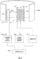
- an ionization gauge 100 of the present disclosure has at least one electron source 105 and at least one collector electrode 110.
- the electron source 105 may be separated from the at least one collector electrode 110 by an optional isolation material 115A which prevents molecules and atoms of gas within a measurement chamber 117 from degrading the electron source(s) 105.
- the ionization gauge 100 also includes an ionization volume and specifically an anode 120.
- Anode 120 and the collector electrode 110 components may have various different configurations, and the gauge 100 is not limited to Fig. 1 .
- the ionization gauge 100 is a Bayard-Alpert type gauge, or an ionization gauge 100 where a heated cathode 105 is used to emit electrons toward an anode grid volume 120.
- the gauge 100 is not limited to any specific ionization gauge configuration and the present invention encompasses several different types of gauges.
- the Bayard-Alpert type gauge 100 is based on the ionization of gas molecules by a constant flow of electrons.
- the negatively charged electrons shown as reference numeral 125 are emitted at a well-controlled selectable rate from a heated cathode 105, and may be released, or accelerated toward a positively charged anode 120.
- the electrons 125 pass into and through the anode 120 and then cycle back and forth through the anode 120.
- the electrons 125 are then retained within the ionization volume of the anode 120. In this space, the electrons 125 collide with the gas molecules to produce positively charged ions. These ions are collected by the one or more ion collector(s) 110.
- Collector 110 is nearly at ground potential, which is negative with regard to the positively charged anode 120. However, this arrangement is not limiting and collector 110 may have various potential differences with respect to the anode 120. At a constant cathode to anode voltage and electron emission current, the rate that positive ions are formed is directly correlated to the density of the gas in the gauge 100. This signal from the collector electrode 110 is detected by an ammeter 135, which is calibrated in units of pressure, for all pressure readings.
- FIG. 1 The embodiment of FIG. 1 is shown as a nude configuration of the Bayard-Alpert type gauge 100. It is also envisioned that non-nude type ionization gauges are also possible.
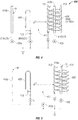
- FIG. 2 shows a specific non-nude type ionization gauge 200 embodying the present disclosure.
- the ionization gauge 200 has similar components to the ionization gauge 100 ( FIG. 1 ) described above with the following additions.
- the ionization gauge 200 is housed in a tube 205. Tube 205 is opened at one end 225 to allow molecules and atoms of gas to enter the measurement chamber 117 through a shield 220.
- the shield 220 and tube 205 form a shield volume.
- An optional second ion collector 210 is added for high pressure measurements of very short mean free paths.
- the shield 220 prevents potentials external to the shield 220 from disturbing the electric charge distribution within the measurement chamber 117.
- the shield 220 is maintained at a reference potential. In one embodiment, the reference potential is ground potential.
- the electron source (for example, a cathode filament) 105 generates electrons (represented by an electron beam 125) within the chamber 117 defined by the envelope 113A.
- the electrons 125 are used in ionizing the gas molecules in the measurement chamber 117.
- the geometrical shape of the filament 105 can be a linear ribbon, a linear wire, a straight ribbon, a curved ribbon, a hairpin wire, or any other shape known in the art.
- the cathode 105 is resistively heated to incandescence with an electrical current from cathode heating power supply 113.
- the thermionically emitted electrons 125 may be released, or accelerated or directed into the measurement chamber 117 towards anode 130. Electrons have a sufficient energy which allows the electrons to be transmitted to the ionization volume of anode 130 and have sufficient energy to enter the anode 130.
- a controller 105a is connected to the cathode bias supply 105b, and the cathode 105 receives a cathode bias voltage of about 30 volts, and a heating voltage from power supply 113 during normal operation. Once the cathode 105 is sufficiently heated, the controller 105a controls the cathode 105 to maintain the appropriate electron current.
- the cathode bias voltage provides sufficient voltage difference from the cathode 105 to the anode 130 to transmit electrons 125 toward the anode grid 130. Ionization occurs over an energy spread both higher and lower than the nominal design energy; see Section 5.7 on ionization gauges in Scientific Foundations of Vacuum Technique by Saul Dushman, 1962 ,
- the controller 105a also is coupled to the anode voltage supply 130a, which delivers a bias voltage to the anode wire grid 130.
- the anode 130 includes an anode bias voltage of about 180 volts when measuring pressure at high vacuum conditions. This difference (180 volts minus 30 volts) provides for 150 eV of energy for the electrons. This is the amount of kinetic energy that is gained by a single free electron 125, when the electron 125 passes through a potential difference that is created between the cathode 105 and the anode grid 130. This 150 eV is sufficient to ionize all gas species present in the ionization gauge volume at high vacuum conditions.
- ionized atoms and molecules can have a maximum energy of about 180 eV when arriving at the ion collector 110.
- These ions formed in the ionization volume of the anode 130 will impact on the collector surface 110, and when operating at high pressure, this large quantity of ions may be excessive and can increase the sputtering rate for unit time.
- sputtering yields can be as large as 0.2 atoms/ion for Ar + ions impacting on tungsten targets with 200 eV kinetic energies, and this kinetic energy can damage the components of the gauge 100 and degrade the ionization gauge 100.
- an ionization gauge design may also decrease sputtering yields.
- the present ionization gauge 100 decreases anode grid bias voltage levels relative to the bias voltage of the collector 110 at high pressure levels to decrease the yield of sputtering collisions.
- a reduction of the anode grid bias voltage to about 80 volts can provide for about a five fold decrease in the sputtering yield for Ar + ions impacting on a tungsten surface of a collector electrode 110.
- the bias voltage of the anode grid 130 the energy of the electrons remains sufficiently high for their collisions with gas atoms and molecules to ionize all gas species present in the ionization volume in the anode grid 130.
- the kinetic energy of the ions is decreased to lessen the energy of ions arriving at the collector 110, envelope walls, and adjacent grounded electrode structures (not shown). This occurs while providing sufficient potential difference between cathode 105 and anode 130 so electrons 125 can enter the anode grid volume 130 while reducing sputtering yields.
- a byproduct of the bias voltage reduction can be a decrease in a sensitivity of the ionization gauge 100. Since this reduction occurs at high pressure levels, or above 10 -4 Torr, the ion current signal received by the collector electrode 110 is relatively large. This received signal/noise level by the collector 110 is adequate for operation of the ionization gauge 100.
- the ionization gauge 100 includes that the controller 105a, reduces a bias voltage of the anode grid 130 in a high pressure mode.
- the controller 105a sufficiently reduces the bias voltage supplied to the anode grid 130 by controlling anode voltage supply 130a.
- the anode grid 130 operates at an anode bias voltage of less than 180 volts. This reduced bias voltage results in reduced electron kinetic energy from 150 eV, or the potential difference between the cathode 105 and the anode grid 130.
- this reduced electron kinetic energy of less than 150 eV is still sufficient to ionize all gas species present in the ionization gauge 100 volume.
- the values of threshold ionization energies required for different monatomic species can range from 3.88 eV (Cs) to 24.58 eV (He), and 15 eV (for oxygen, nitrogen, and hydrogen).
- Cs 3.88 eV
- He 24.58 eV
- 15 eV for oxygen, nitrogen, and hydrogen
- the controller 105a outputs a control signal to the anode voltage supply 130a to reduce the anode bias voltage supply from 180 volts to 80 volts, or less.
- the electron energy, or difference between the bias voltage of the cathode 105 and the anode 130 is 50 eV. This amount is sufficient to ionize the gas at high pressures without causing the degradation of the ionization gauge 100 that is attributed to high sputtering yields. This results in a decrease in the yield of sputtering impacts for Ar + ions impinging on tungsten collector electrode 110 surface, and this 50eV value may provide for a five-fold decrease in the sputtering yield. It should be appreciated that other anode bias voltages are also envisioned, and the present ionization gauge 100 is not limited to any specific anode bias voltage reduction.
- the ionization gauge 100 is configured so the anode 130 operates at an initial bias voltage at one pressure and then automatically operates at a reduced bias voltage at high pressures, such as, for example, above about 10 -4 Torr.
- the controller 105a can switch automatically the bias voltage so a potential difference between the anode 130 and the collector electrode 110 is less than 90 volts.
- the bias voltage of the anode 130 may be switched from about 180 volts to about 80 volts so a potential difference between the anode 130 and the collector electrode 110 is about 80 volts.
- the cathode filament 105 can be supplied less than 20 volts, or can be supplied at about 10 volts so that an adequate voltage difference from the cathode 105 to the anode 130 is maintained.
- the anode 130 can operate at a reduced bias voltage at high pressures or above about 10 -4 Torr.
- the controller 105a may control the anode bias voltage supply 130a to increase the anode bias voltage supply.
- the potential difference can be increased for sufficient ionization energies. This ensures that the electrons have sufficient energy to efficiently ionize a very low density of gas.
- the bias voltage of the cathode 105 cannot be too low, and has to be above the collector electrode 110, and the envelope wall 113A.
- the cathode 105 is about 10 volts above the collector electrode 110.
- the present ionization gauge 100 is not limited to controlling the bias voltage of the anode grid 130. It is envisioned that the bias voltage of the filament 105 and the collector electrode 110 can also be modified by controller 105a. The bias voltage of the filament 105 and the collector electrode 110 can also be modified by controller 105a to minimize sputtering yields, and to extend the life of the ionization gauge 100. It should also be appreciated that the ionization gauge 100 may be configured as a triode ionization gauge (not shown) or another specific type of gauge 100. It should be appreciated that the present ionization gauge 100 is not limited to a BA ionization gauges, and may include a cold cathode electron emitter 105.
- the energy of the ions can be determined by the difference between the ion collector 110 and the anode 130.
- the anode 130 can be kept constant and the collector 110 can be raised above ground potential to reduce the energy of the ions.
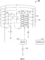
- the ionization gauge is a Bayard-Alpert ionization gauge 400; however, gauge 400 can alternatively be manufactured as a cold electron emitter ionization gauge 400 with a cold electron emitter source.
- Gauge 400 includes an anode grid 430, a cathode filament 405, and a first ion collector electrode 410a.
- the anode 430 surrounds the first ion collector electrode 410a.
- Bayard-Alpert ionization gauges are used to measure pressure in the high vacuum and ultrahigh vacuum environment. Pressure measurement capabilities become compromised at high vacuum levels or at about 10 -4 Torr, and become even more limited at about 10 -3 Torr.
- One observed problem is that at higher pressures electrons scatter on their way to the anode grid 430. Long electron trajectories are compromised by scattering collisions with neutral species. Additionally, the ability to effectively collect ions inside the anode 130 is compromised as the ion density builds up around the collector post 410a.
- the present ionization gauge 400 preferably collects ions at high pressure that are located outside of the anode grid 430. This collection extends the effective pressure operating range above 10 -4 Torr.
- a second ion collector 410b can be positioned in a location near or closer to the cathode filament 405.
- Collector electrode 410b assures efficient collection of ions, which are located near the electron source 405 at high pressures.
- Collector electrode 410b is configured for use as an alternative second ion collector electrode 410b to collect ions formed outside of the anode 430 at high pressures.
- Second collector electrode 410b extends the operating range of the gauge 400 to levels above 100 mTorr with a minimum detectable pressure limit as low as 10 -5 Torr. This provides for better overlap with a heat loss or a capacitance diaphragm pressure sensor in a combination gauge. This also provides for no lost time attributed to sensor switching during process cycles in PVD, semiconductor, and hard disk manufacturing processes. This also preserves the base measurement capabilities expected from the gauge 400 and which are needed for a vacuum qualification of the instrument.
- the ionization gauge 400 may also include that the second ion collector electrode 410b is positioned near the filament 405, and is supported in an extra filament support post (not shown). This is advantageous in a retrofit installation of the second ion collector electrode 410b to an existing gauge.
- the second collector electrode 410b is supported in another support structure, such as, for example, a support post which is located near the anode grid 430.
- Various support configurations are possible.
- the second ion collector electrode 410b can be a post 410b as shown in FIG. 4 , or an electrode plate 410c ( FIG. 5 ), or can be formed as an electrode grid or wall 410d ( FIG. 6 ).
- the second ion collector electrode 410c of FIG. 5 can be connected to an ammeter 435a, or may alternatively be operatively coupled to the collector electrode 410a, which is connected to the ammeter 435.
- the second collector 410b can be connected to a different ammeter 435a, or the same ammeter 435 as collector 410a to measure ions, and gauge 400 is not limited to any specific configuration.
- the second ion collector may be formed as an intermediate wall 410d.
- Collector wall 410d surrounds the anode 430 and the first ion collector electrode 410a and the cathode 405.
- the intermediate wall 410d may be connected to a switch 440 ( FIG. 6 ).
- Switch 440 provides for two modes of collecting ions, namely a high pressure operation mode and a normal (high vacuum) operation mode.
- the ionization gauge 400 collects ions using the second ion collector grid or wall 410d.
- the first ion collector electrode 410a collects ions.
- Gauge 400 can be switched between collecting ions using collector 410a or collector 410d using switch 440, which can be manually controlled or electronically controlled.
- Pressure is measured using detected signals received by the ammeter 435 which is connected to the controller 450.
- One collector would be used at high pressures, while at a different pressure, the other collector electrode would be used to measure pressure.
- the intermediate wall 410d can advantageously be installed in a retrofit manner to existing BA ionization gauges 400.
- a switch 440 can be installed in a retrofit manner and connected between the ammeter 435 and the first ion collector electrode 410a in an existing BA ionization gauge 400.
- the cathode emission level may remain constant, as well as, the voltage bias on the anode 430.
- the ammeter 435 would detect a pressure of 1 x 10 -4 Torr, and then output a signal to a controller 450.
- the controller 450 in response, would then switch from collecting ions using the first ion collector electrode 410a to collecting ions using the second ion collector 410d to collect ions formed closer to the filament 405.
- the ion current measurement may effectively self-switch from one collector to another collector whereby the ion current diminishes significantly from the inside collector as the pressure increases from above about 10 -3 Torr, and then diminishes significantly from the outside collector as the pressure decreases below 10 -3 Torr. It should be appreciated that ion current from the outside collector is generally not a concern below 10 -4 Torr.
- the ionization gauge 400 may be formed with more than two ion collector electrodes 410a, 410d.
- Gauge 400 may include a second ion collector 410d, and a third ion collector electrode (not shown), or more collector electrodes being placed near the filament 405 to collect ions at high pressures.
- Various configurations are possible and within the scope of the present disclosure.
- an ionization gauge 100 may be configured in a Schultz-Phelps geometry with the anode 115 being arranged as a flat plate, the ion collector 110 as a parallel flat plate, and the electron source 105 positioned between those two plates 110, 115.
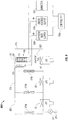
- the ionization gauge 100 preferably can be used with a cluster tool 800 or another multi-chamber tool for processing operations.
- the cluster tool 800 may include a load lock chamber 805 connected to a transfer chamber 810 by a valve 810a.
- the load lock chamber 805 is sealed from ambient conditions by a valve 810b.
- Both a single chamber and multi-chamber cluster tools 800 are envisioned, and the ionization gauge 100 can be used in either a single chamber or a multi-chamber tool configuration. It should be appreciated that the ionization gauge 100 is not limited for use with a vacuum chamber, and can be used in any manufacturing chamber known in the art.
- the cluster tool 800 may also include a process module 815.
- Process module 815 is also connected to the transfer chamber 810 by a valve 810c.
- the tool 800 may includes multiple process modules 815 and multiple load lock chambers 805, and the configuration shown is not limiting.
- the load lock chamber 805 may include a rough pump RP1, which also is connected to the load lock chamber 805 by a valve V 1 .
- Each of the load lock chamber 805, the transfer chamber 810, and the process module 815 may include at least one vacuum pump Vp 1 , Vp 2 , and Vp 3 .
- the vacuum pump may be a cryogenic vacuum pump, or another pump, such as a turbo pump or water vapor pump. Various pumping configurations are possible and within the scope of the present disclosure.
- a wafer (not shown) may be introduced into the load lock chamber 805, and pumped to vacuum conditions using the rough pump Rp 1 and the vacuum pump Vpi.
- the wafer can be manipulated to the transfer chamber 810 through the valve 810a, and then the wafer can be placed in the process module 815 through the valve 810c for various deposition operations.
- the ionization gauge 100 may be placed in one of the chambers 805, 810, or 815 of the cluster tool 800.
- the ionization gauge 100 is shown in the process module 815, but is not limited to any specific chamber or location, and can be placed outside of the chamber or tool 800.
- the ionization gauge 100 preferably can measure pressure both base pressure (high vacuum) and higher processing pressures (mostly in the mTorr range), however this is not limiting and various operational parameters for measurement are possible and within the scope of the present disclosure.
- the ionization gauge 100 can be used to measure pressure in the manufacture of flat panel displays, magnetic media operations, solar cells, optical coating operations, semiconductor manufacturing operations, and other manufacturing process operations.
- Such processes may include physical vapor deposition, plasma vapor deposition (PVD), chemical vapor deposition (CVD), atomic layer deposition (ALD), plasma etch operations, implantation operations, oxidation/diffusion, forming of nitrides, vacuum lithography, dry strip operations, epitaxy operations (EPI), rapid thermal processing (RTP) operations, extreme ultraviolet lithography operations, and others.
- the ionization gauge 100 may also be operable with one or more analytical tools, such as, for example, a microscope or a mass spectrometer.
- Mass spectrometers may include gas chromatograph instruments (GC), liquid chromatograph instruments (LC), ion trap instruments, magnetic sector spectrometers instruments, double-focusing instruments, time-of-flight instruments (TOF), rotating field instruments, ion mobility instruments, linear quadrupole instruments, and others.
- GC gas chromatograph instruments
- LC liquid chromatograph instruments
- TOF time-of-flight instruments
- TOF rotating field instruments
- ion mobility instruments ion mobility instruments
- linear quadrupole instruments and others.
- Surface analytical instruments 820 that can be used in connection with the ionization gauge 100, and with the cluster tool 800 (or without the cluster tool 800) may also include scanning electron microscopes, energy dispersive X-ray spectroscopy instruments (EOS/XPS), scanning auger microanalysis instruments (Auger/SAM), glow discharge mass spectroscopy instruments (GDMS), electron spectroscopy for chemical analysis instruments (ESCA), atomic force microscopy/scanning probe microscopy instruments (AFM/SPM), Fourier transform infrared spectroscopy instruments (FTIR), wavelength dispersive X-ray spectroscopy instruments (WDS), inductively coupled plasma mass spectroscopy instruments (ICPMS), x-ray fluorescence instruments (XRF), neutron activation analysis instruments (NAA), metrology instruments, and others. It should be appreciated that this listing is not exhaustive and the gauge 100 may be used with other instruments not enumerated above.
- EOS/XPS energy dispersive X-ray spectroscopy instruments
Claims (16)
- Ionisationsmanometer zum Messen von Druck, das Folgendes umfasst:wenigstens eine Elektronenquelle (105), die Elektronen erzeugt;eine Kollektorelektrode (110), die durch Stoß zwischen Elektronen und Gasmolekülen gebildete Ionen sammelt;eine Anode (130), konfiguriert zum Arbeiten mit einer Vorspannung relativ zu einer Vorspannung der Kollektorelektrode während der Druckmessung; unddadurch gekennzeichnet, dass das Ionisationsmanometer eine Steuerung (105a) umfasst, die zum Ändern der Vorspannung der Anode (130) relativ zur Vorspannung der Kollektorelektrode (110) auf der Basis eines vorbestimmten Drucks konfiguriert ist.
- Ionisationsmanometer nach Anspruch 1, wobei die Steuerung (105a) zum Betreiben der Anode (130) mit einer anfänglichen Vorspannung bei Drücken unter etwa 10-4 Torr konfiguriert ist und wobei die Steuerung (105a) zum Betreiben der Anode (130) mit einer reduzierten Vorspannung bei Drücken über etwa 10-4 Torr konfiguriert ist.
- Ionisationsmanometer nach Anspruch 1, wobei die Steuerung (105a) zum Ändern der Vorspannung der Anode (130) auf der Basis eines Druckmodus des Ionisationsmanometers konfiguriert ist.
- Ionisationsmanometer nach einem vorherigen Anspruch, wobei die Steuerung (105a) zum Ändern der Anodenvorspannung konfiguriert ist, so dass eine Potentialdifferenz zwischen der Anode (130) und der Kollektorelektrode (110) kleiner als 90 Volt ist.
- Ionisationsmanometer nach einem vorherigen Anspruch, wobei die Elektronenquelle (105) zum Arbeiten mit einer Vorspannung von weniger als 20 Volt konfiguriert ist.
- Ionisationsmanometer nach einem vorherigen Anspruch, wobei die Elektronenquelle (105) sich außerhalb der Anode (130) befindet und die Kollektorelektrode (110) sich innerhalb der Anode befindet.
- Ionisationsmanometer nach einem vorherigen Anspruch, wobei ein Ionisationsvolumen durch eine plattenförmige Anode (115) und eine plattenförmige Kollektorelektrode (110) definiert wird und wobei die Elektronen erzeugende Elektronenquelle (105) allgemein zwischen der plattenförmigen Anode und der plattenförmigen Kollektorelektrode ist.
- Ionisationsmanometer nach einem vorherigen Anspruch, wobei die Steuerung die Vorspannung der Anode in einem Hochdruckmodus reduziert.
- Ionisationsmanometer nach einem vorherigen Anspruch, wobei die Anodenvorspannung auf eine Spannung von weniger als 180 Volt reduziert wird.
- Verfahren zum Messen eines Gasdrucks von Gasmolekülen und Atomen, das die folgenden Schritte beinhaltet:Produzieren von Elektronen von wenigstens einer Elektronenquelle (105);Übertragen der Elektronen zu einer Anode (130) zum Bilden von Ionen;Betreiben der Anode mit einer Vorspannung relativ zu einer Vorspannung einer Kollektorelektrode (110);Sammeln von durch Stoß zwischen den Elektronen und den Gasmolekülen und Atomen gebildeten Ionen; undgekennzeichnet durch Ändern, mit einer Steuerung (105a), der Vorspannung der Anode relativ zur Vorspannung der Kollektorelektrode auf der Basis eines Druckmodus des Ionisationsmanometers.
- Verfahren nach Anspruch 10, wobei die Vorspannung der Anode (130) relativ zur Vorspannung der Kollektorelektrode (110) geändert wird, um einen Ertrag von Sputter-Kollisionen zu verringern.
- Verfahren nach Anspruch 10 oder Anspruch 11, wobei die Anode (130) mit einer anfänglichen Vorspannung bei Drücken unter etwa 10-4 Torr arbeitet und wobei die Anode mit einer reduzierten Vorspannung bei Drücken über etwa 10-4 Torr arbeitet.
- Verfahren nach einem der Ansprüche 10 bis 12, wobei die Anodenvorspannung so geändert wird, dass eine Potentialdifferenz zwischen der Anode und dem Kollektor kleiner als 90 Volt ist.
- Verfahren nach einem der Ansprüche 10 bis 13, wobei die Elektronenquelle mit einer Vorspannung von weniger als 20 Volt arbeitet.
- Verfahren nach einem der Ansprüche 10 bis 14, wobei die Steuerung die Vorspannung der Anode in einem Hochdruckmodus reduziert.
- Verfahren nach einem der Ansprüche 10 bis 15, wobei die Anodenvorspannung auf eine Spannung von weniger als 180 Volt reduziert wird.
Applications Claiming Priority (2)
| Application Number | Priority Date | Filing Date | Title |
|---|---|---|---|
| US6663108P | 2008-02-21 | 2008-02-21 | |
| PCT/US2009/034460 WO2009105506A1 (en) | 2008-02-21 | 2009-02-19 | Ionization gauge with operational parameters and geometry designed for high pressure operation |
Publications (3)
| Publication Number | Publication Date |
|---|---|
| EP2252869A1 EP2252869A1 (de) | 2010-11-24 |
| EP2252869A4 EP2252869A4 (de) | 2017-05-10 |
| EP2252869B1 true EP2252869B1 (de) | 2018-12-12 |
Family
ID=40985893
Family Applications (1)
| Application Number | Title | Priority Date | Filing Date |
|---|---|---|---|
| EP09713559.4A Active EP2252869B1 (de) | 2008-02-21 | 2009-02-19 | Ionisierungsmessgerät mit für hochdruckbetrieb ausgelegten betriebsparametern und geometrie |
Country Status (5)
| Country | Link |
|---|---|
| US (2) | US8648604B2 (de) |
| EP (1) | EP2252869B1 (de) |
| JP (1) | JP5728728B2 (de) |
| CN (1) | CN101990630B (de) |
| WO (1) | WO2009105506A1 (de) |
Families Citing this family (17)
| Publication number | Priority date | Publication date | Assignee | Title |
|---|---|---|---|---|
| JP5762749B2 (ja) * | 2007-12-19 | 2015-08-12 | エム ケー エス インストルメンツインコーポレーテッドMks Instruments,Incorporated | 冷電子増倍放出源を備える電離真空計 |
| EP2252869B1 (de) | 2008-02-21 | 2018-12-12 | MKS Instruments, Inc. | Ionisierungsmessgerät mit für hochdruckbetrieb ausgelegten betriebsparametern und geometrie |
| WO2012078403A1 (en) * | 2010-12-07 | 2012-06-14 | 3M Innovative Properties Company | Ionization balance device with shielded capacitor circuit for ion balance measurements and adjustments |
| DK2800960T3 (en) | 2012-02-08 | 2019-01-28 | Mks Instr Inc | Ionization meter for high pressure operation |
| US9454158B2 (en) | 2013-03-15 | 2016-09-27 | Bhushan Somani | Real time diagnostics for flow controller systems and methods |
| DE102014205695B4 (de) * | 2014-03-27 | 2016-01-28 | Christof-Herbert Diener | Niederdruckplasmaanlage mit sequentieller Steuerung |
| US9588004B2 (en) | 2014-11-07 | 2017-03-07 | Mks Instruments, Inc. | Long lifetime cold cathode ionization vacuum gauge design |
| TWI739300B (zh) | 2015-01-15 | 2021-09-11 | 美商Mks儀器公司 | 離子化計及其製造方法 |
| WO2016151997A1 (ja) * | 2015-03-23 | 2016-09-29 | 株式会社アルバック | 三極管型電離真空計 |
| US9927317B2 (en) * | 2015-07-09 | 2018-03-27 | Mks Instruments, Inc. | Ionization pressure gauge with bias voltage and emission current control and measurement |
| WO2018111684A1 (en) * | 2016-12-13 | 2018-06-21 | Mks Instruments, Inc. | Anode electrode shield for inverted magnetron cold cathode ionization gauge |
| US10983537B2 (en) | 2017-02-27 | 2021-04-20 | Flow Devices And Systems Inc. | Systems and methods for flow sensor back pressure adjustment for mass flow controller |
| CN107993908B (zh) * | 2017-11-27 | 2019-11-15 | 温州大学 | 一种基于场发射阴极电子源的电离真空计及其应用方法 |
| US10928265B2 (en) * | 2018-05-29 | 2021-02-23 | Mks Instruments, Inc. | Gas analysis with an inverted magnetron source |
| US10566168B1 (en) * | 2018-08-10 | 2020-02-18 | John Bennett | Low voltage electron transparent pellicle |
| CN110082420B (zh) * | 2019-04-23 | 2021-06-11 | 上海交通大学 | 基于正弦宽频电场下空间电荷测量的电介质陷阱检测系统 |
| US11187827B1 (en) * | 2019-07-26 | 2021-11-30 | Board Of Regents, The University Of Texas System | Spinning aperture neutral drift sensor (SANDS) |
Family Cites Families (36)
| Publication number | Priority date | Publication date | Assignee | Title |
|---|---|---|---|---|
| US2605431A (en) | 1950-03-30 | 1952-07-29 | Westinghouse Electric Corp | Ionization vacuum gauge |
| US3353048A (en) * | 1964-11-23 | 1967-11-14 | Gen Telephone & Elect | Ionization gauge for monitoring the flow of evaporant material |
| US4093913A (en) * | 1976-03-24 | 1978-06-06 | Varian Associates, Inc. | Vacuum measuring ionization apparatus control |
| US4270091A (en) * | 1978-01-25 | 1981-05-26 | Varian Associates, Inc. | Apparatus and method for measuring pressures and indicating leaks with optical analysis |
| US4307323A (en) * | 1980-04-04 | 1981-12-22 | Granville-Phillips Company | Vacuum gauge |
| US4714891A (en) * | 1985-09-23 | 1987-12-22 | Granville-Phillips Company | Method and apparatus for improving the safety and extending the range of ionization gauge systems |
| JPS62218834A (ja) * | 1986-03-20 | 1987-09-26 | Seiko Instr & Electronics Ltd | 気体圧力計 |
| US5422573A (en) * | 1990-04-11 | 1995-06-06 | Granville-Phillips Company | Ionization gauge and method of using and calibrating same |
| US5128617A (en) * | 1990-04-11 | 1992-07-07 | Granville-Phillips Company | Ionization vacuum gauge with emission of electrons in parallel paths |
| FR2679653B1 (fr) * | 1991-07-23 | 1993-09-24 | Commissariat Energie Atomique | Vacumetre a ionisation. |
| US5866901A (en) * | 1996-12-05 | 1999-02-02 | Mks Instruments, Inc. | Apparatus for and method of ion detection using electron multiplier over a range of high pressures |
| JPH10213509A (ja) * | 1997-01-27 | 1998-08-11 | Ulvac Japan Ltd | 圧力測定装置 |
| JP3833776B2 (ja) * | 1997-04-08 | 2006-10-18 | 株式会社アルバック | 広帯域電離真空計 |
| EP0980512A1 (de) * | 1997-05-09 | 2000-02-23 | The Fredericks Company | Vacuum messandornung nach bayard-alpert mit neutralisation des x-ray effectes |
| JP4339948B2 (ja) * | 1999-02-25 | 2009-10-07 | キヤノンアネルバ株式会社 | 熱陰極電離真空計 |
| JP4493139B2 (ja) * | 2000-02-02 | 2010-06-30 | キヤノンアネルバ株式会社 | 電離真空計 |
| US6566884B2 (en) * | 2001-09-13 | 2003-05-20 | Duniway Stockroom Corporation | Ionization vacuum pressure gauge |
| GB2381652A (en) * | 2001-11-01 | 2003-05-07 | Boc Group Plc | Cold cathode ionisation vacuum gauge |
| US6756785B2 (en) * | 2002-07-25 | 2004-06-29 | Mks Instruments, Inc. | Pressure controlled degas system for hot cathode ionization pressure gauges |
| CN1176355C (zh) * | 2002-10-17 | 2004-11-17 | 上海交通大学 | 屏蔽罩静电荷灭弧室真空度检测方法及其装置 |
| JP4199050B2 (ja) * | 2003-05-22 | 2008-12-17 | 株式会社アルバック | 四重極型質量分析計とそれを有する真空装置 |
| ITTO20030626A1 (it) * | 2003-08-08 | 2005-02-09 | Varian Spa | Vacuometro a ionizzazione. |
| CN100555552C (zh) * | 2004-07-30 | 2009-10-28 | 清华大学 | 真空规管 |
| EP1698878A1 (de) * | 2005-03-04 | 2006-09-06 | Inficon GmbH | Elektrodenanordnung und Druckmessvorrichtung |
| JP2006266854A (ja) * | 2005-03-23 | 2006-10-05 | Shinku Jikkenshitsu:Kk | 全圧測定電極付き四重極質量分析計及びこれを用いる真空装置 |
| EP1890124A4 (de) * | 2005-05-09 | 2012-08-22 | Ampere Inc | Ionisierungsunterdruckmessvorrichtung |
| JP4141472B2 (ja) | 2005-12-28 | 2008-08-27 | シャープ株式会社 | 画像処理装置、画像処理方法、及びプログラム |
| US7525101B2 (en) * | 2006-05-26 | 2009-04-28 | Thermo Niton Analyzers Llc | Neutron and gamma ray monitor |
| US7429863B2 (en) * | 2006-07-18 | 2008-09-30 | Brooks Automation, Inc. | Method and apparatus for maintaining emission capabilities of hot cathodes in harsh environments |
| CN101303264B (zh) * | 2007-05-09 | 2010-05-26 | 清华大学 | 电离规 |
| US7768267B2 (en) * | 2007-07-11 | 2010-08-03 | Brooks Automation, Inc. | Ionization gauge with a cold electron source |
| JP5158585B2 (ja) * | 2007-10-12 | 2013-03-06 | 株式会社ネットコムセック | 電源装置及び高周波回路システム |
| EP2252869B1 (de) | 2008-02-21 | 2018-12-12 | MKS Instruments, Inc. | Ionisierungsmessgerät mit für hochdruckbetrieb ausgelegten betriebsparametern und geometrie |
| US7906971B2 (en) * | 2008-10-14 | 2011-03-15 | Itt Manufacturing Enterprises, Inc. | Molecular shield for an ionizaton vacuum gauge |
| JP2010213509A (ja) | 2009-03-11 | 2010-09-24 | Univ Of Fukui | 横磁束型同期機 |
| JP2010281911A (ja) | 2009-06-02 | 2010-12-16 | Seiko Epson Corp | 電気光学装置 |
-
2009
- 2009-02-19 EP EP09713559.4A patent/EP2252869B1/de active Active
- 2009-02-19 JP JP2010547736A patent/JP5728728B2/ja active Active
- 2009-02-19 CN CN2009801125552A patent/CN101990630B/zh active Active
- 2009-02-19 WO PCT/US2009/034460 patent/WO2009105506A1/en active Application Filing
-
2010
- 2010-08-20 US US12/860,050 patent/US8648604B2/en active Active
-
2014
- 2014-02-06 US US14/174,386 patent/US9404827B2/en active Active
Non-Patent Citations (1)
| Title |
|---|
| None * |
Also Published As
| Publication number | Publication date |
|---|---|
| EP2252869A4 (de) | 2017-05-10 |
| WO2009105506A1 (en) | 2009-08-27 |
| US9404827B2 (en) | 2016-08-02 |
| CN101990630A (zh) | 2011-03-23 |
| EP2252869A1 (de) | 2010-11-24 |
| CN101990630B (zh) | 2013-08-14 |
| US20140152320A1 (en) | 2014-06-05 |
| US8648604B2 (en) | 2014-02-11 |
| US20110062961A1 (en) | 2011-03-17 |
| JP5728728B2 (ja) | 2015-06-03 |
| JP2011513709A (ja) | 2011-04-28 |
Similar Documents
| Publication | Publication Date | Title |
|---|---|---|
| EP2252869B1 (de) | Ionisierungsmessgerät mit für hochdruckbetrieb ausgelegten betriebsparametern und geometrie | |
| US8686733B2 (en) | Ionization gauge having electron multiplier cold emission source | |
| US9383286B2 (en) | Ionization gauge with emission current and bias potential control | |
| US9952113B2 (en) | Ionization gauge for high pressure operation | |
| DK2252869T3 (en) | Ionization meter with operating parameters and geometry designed for high pressure operation | |
| KR20190006434A (ko) | 삼극관형 전리 진공계 및 압력 측정 방법 | |
| Li et al. | Vacuum Science and Technology for Accelerator Vacuum Systems | |
| Schulz | Sputter-ion pumps | |
| Warshawsky | Classified abstracts 6094-6102 | |
| Coggiola et al. | Systematic investigation of negative ion production from low‐work function surfaces |
Legal Events
| Date | Code | Title | Description |
|---|---|---|---|
| PUAI | Public reference made under article 153(3) epc to a published international application that has entered the european phase |
Free format text: ORIGINAL CODE: 0009012 |
|
| 17P | Request for examination filed |
Effective date: 20100914 |
|
| AK | Designated contracting states |
Kind code of ref document: A1 Designated state(s): AT BE BG CH CY CZ DE DK EE ES FI FR GB GR HR HU IE IS IT LI LT LU LV MC MK MT NL NO PL PT RO SE SI SK TR |
|
| AX | Request for extension of the european patent |
Extension state: AL BA RS |
|
| DAX | Request for extension of the european patent (deleted) | ||
| RAP1 | Party data changed (applicant data changed or rights of an application transferred) |
Owner name: MKS INSTRUMENTS, INC. |
|
| RA4 | Supplementary search report drawn up and despatched (corrected) |
Effective date: 20170410 |
|
| RIC1 | Information provided on ipc code assigned before grant |
Ipc: G01N 27/62 20060101ALI20170404BHEP Ipc: G01L 21/32 20060101AFI20170404BHEP Ipc: H01J 37/05 20060101ALI20170404BHEP Ipc: G01L 21/34 20060101ALI20170404BHEP Ipc: H01J 41/04 20060101ALI20170404BHEP |
|
| STAA | Information on the status of an ep patent application or granted ep patent |
Free format text: STATUS: EXAMINATION IS IN PROGRESS |
|
| 17Q | First examination report despatched |
Effective date: 20180409 |
|
| GRAP | Despatch of communication of intention to grant a patent |
Free format text: ORIGINAL CODE: EPIDOSNIGR1 |
|
| STAA | Information on the status of an ep patent application or granted ep patent |
Free format text: STATUS: GRANT OF PATENT IS INTENDED |
|
| INTG | Intention to grant announced |
Effective date: 20180615 |
|
| GRAS | Grant fee paid |
Free format text: ORIGINAL CODE: EPIDOSNIGR3 |
|
| GRAJ | Information related to disapproval of communication of intention to grant by the applicant or resumption of examination proceedings by the epo deleted |
Free format text: ORIGINAL CODE: EPIDOSDIGR1 |
|
| GRAL | Information related to payment of fee for publishing/printing deleted |
Free format text: ORIGINAL CODE: EPIDOSDIGR3 |
|
| STAA | Information on the status of an ep patent application or granted ep patent |
Free format text: STATUS: EXAMINATION IS IN PROGRESS |
|
| GRAR | Information related to intention to grant a patent recorded |
Free format text: ORIGINAL CODE: EPIDOSNIGR71 |
|
| STAA | Information on the status of an ep patent application or granted ep patent |
Free format text: STATUS: GRANT OF PATENT IS INTENDED |
|
| GRAA | (expected) grant |
Free format text: ORIGINAL CODE: 0009210 |
|
| STAA | Information on the status of an ep patent application or granted ep patent |
Free format text: STATUS: THE PATENT HAS BEEN GRANTED |
|
| INTC | Intention to grant announced (deleted) | ||
| AK | Designated contracting states |
Kind code of ref document: B1 Designated state(s): AT BE BG CH CY CZ DE DK EE ES FI FR GB GR HR HU IE IS IT LI LT LU LV MC MK MT NL NO PL PT RO SE SI SK TR |
|
| INTG | Intention to grant announced |
Effective date: 20181105 |
|
| REG | Reference to a national code |
Ref country code: GB Ref legal event code: FG4D |
|
| REG | Reference to a national code |
Ref country code: CH Ref legal event code: EP |
|
| REG | Reference to a national code |
Ref country code: AT Ref legal event code: REF Ref document number: 1076655 Country of ref document: AT Kind code of ref document: T Effective date: 20181215 |
|
| REG | Reference to a national code |
Ref country code: DE Ref legal event code: R096 Ref document number: 602009056161 Country of ref document: DE |
|
| REG | Reference to a national code |
Ref country code: IE Ref legal event code: FG4D |
|
| REG | Reference to a national code |
Ref country code: CH Ref legal event code: NV Representative=s name: BOVARD AG PATENT- UND MARKENANWAELTE, CH |
|
| REG | Reference to a national code |
Ref country code: DK Ref legal event code: T3 Effective date: 20190318 |
|
| REG | Reference to a national code |
Ref country code: NL Ref legal event code: MP Effective date: 20181212 |
|
| REG | Reference to a national code |
Ref country code: LT Ref legal event code: MG4D |
|
| PG25 | Lapsed in a contracting state [announced via postgrant information from national office to epo] |
Ref country code: ES Free format text: LAPSE BECAUSE OF FAILURE TO SUBMIT A TRANSLATION OF THE DESCRIPTION OR TO PAY THE FEE WITHIN THE PRESCRIBED TIME-LIMIT Effective date: 20181212 Ref country code: LT Free format text: LAPSE BECAUSE OF FAILURE TO SUBMIT A TRANSLATION OF THE DESCRIPTION OR TO PAY THE FEE WITHIN THE PRESCRIBED TIME-LIMIT Effective date: 20181212 Ref country code: BG Free format text: LAPSE BECAUSE OF FAILURE TO SUBMIT A TRANSLATION OF THE DESCRIPTION OR TO PAY THE FEE WITHIN THE PRESCRIBED TIME-LIMIT Effective date: 20190312 Ref country code: HR Free format text: LAPSE BECAUSE OF FAILURE TO SUBMIT A TRANSLATION OF THE DESCRIPTION OR TO PAY THE FEE WITHIN THE PRESCRIBED TIME-LIMIT Effective date: 20181212 Ref country code: NO Free format text: LAPSE BECAUSE OF FAILURE TO SUBMIT A TRANSLATION OF THE DESCRIPTION OR TO PAY THE FEE WITHIN THE PRESCRIBED TIME-LIMIT Effective date: 20190312 Ref country code: LV Free format text: LAPSE BECAUSE OF FAILURE TO SUBMIT A TRANSLATION OF THE DESCRIPTION OR TO PAY THE FEE WITHIN THE PRESCRIBED TIME-LIMIT Effective date: 20181212 Ref country code: FI Free format text: LAPSE BECAUSE OF FAILURE TO SUBMIT A TRANSLATION OF THE DESCRIPTION OR TO PAY THE FEE WITHIN THE PRESCRIBED TIME-LIMIT Effective date: 20181212 |
|
| REG | Reference to a national code |
Ref country code: AT Ref legal event code: MK05 Ref document number: 1076655 Country of ref document: AT Kind code of ref document: T Effective date: 20181212 |
|
| PG25 | Lapsed in a contracting state [announced via postgrant information from national office to epo] |
Ref country code: SE Free format text: LAPSE BECAUSE OF FAILURE TO SUBMIT A TRANSLATION OF THE DESCRIPTION OR TO PAY THE FEE WITHIN THE PRESCRIBED TIME-LIMIT Effective date: 20181212 Ref country code: GR Free format text: LAPSE BECAUSE OF FAILURE TO SUBMIT A TRANSLATION OF THE DESCRIPTION OR TO PAY THE FEE WITHIN THE PRESCRIBED TIME-LIMIT Effective date: 20190313 |
|
| PG25 | Lapsed in a contracting state [announced via postgrant information from national office to epo] |
Ref country code: NL Free format text: LAPSE BECAUSE OF FAILURE TO SUBMIT A TRANSLATION OF THE DESCRIPTION OR TO PAY THE FEE WITHIN THE PRESCRIBED TIME-LIMIT Effective date: 20181212 |
|
| PG25 | Lapsed in a contracting state [announced via postgrant information from national office to epo] |
Ref country code: PT Free format text: LAPSE BECAUSE OF FAILURE TO SUBMIT A TRANSLATION OF THE DESCRIPTION OR TO PAY THE FEE WITHIN THE PRESCRIBED TIME-LIMIT Effective date: 20190412 Ref country code: IT Free format text: LAPSE BECAUSE OF FAILURE TO SUBMIT A TRANSLATION OF THE DESCRIPTION OR TO PAY THE FEE WITHIN THE PRESCRIBED TIME-LIMIT Effective date: 20181212 Ref country code: CZ Free format text: LAPSE BECAUSE OF FAILURE TO SUBMIT A TRANSLATION OF THE DESCRIPTION OR TO PAY THE FEE WITHIN THE PRESCRIBED TIME-LIMIT Effective date: 20181212 Ref country code: PL Free format text: LAPSE BECAUSE OF FAILURE TO SUBMIT A TRANSLATION OF THE DESCRIPTION OR TO PAY THE FEE WITHIN THE PRESCRIBED TIME-LIMIT Effective date: 20181212 |
|
| PG25 | Lapsed in a contracting state [announced via postgrant information from national office to epo] |
Ref country code: IS Free format text: LAPSE BECAUSE OF FAILURE TO SUBMIT A TRANSLATION OF THE DESCRIPTION OR TO PAY THE FEE WITHIN THE PRESCRIBED TIME-LIMIT Effective date: 20190412 Ref country code: RO Free format text: LAPSE BECAUSE OF FAILURE TO SUBMIT A TRANSLATION OF THE DESCRIPTION OR TO PAY THE FEE WITHIN THE PRESCRIBED TIME-LIMIT Effective date: 20181212 Ref country code: SK Free format text: LAPSE BECAUSE OF FAILURE TO SUBMIT A TRANSLATION OF THE DESCRIPTION OR TO PAY THE FEE WITHIN THE PRESCRIBED TIME-LIMIT Effective date: 20181212 Ref country code: EE Free format text: LAPSE BECAUSE OF FAILURE TO SUBMIT A TRANSLATION OF THE DESCRIPTION OR TO PAY THE FEE WITHIN THE PRESCRIBED TIME-LIMIT Effective date: 20181212 |
|
| REG | Reference to a national code |
Ref country code: DE Ref legal event code: R097 Ref document number: 602009056161 Country of ref document: DE |
|
| PLBE | No opposition filed within time limit |
Free format text: ORIGINAL CODE: 0009261 |
|
| STAA | Information on the status of an ep patent application or granted ep patent |
Free format text: STATUS: NO OPPOSITION FILED WITHIN TIME LIMIT |
|
| PG25 | Lapsed in a contracting state [announced via postgrant information from national office to epo] |
Ref country code: SI Free format text: LAPSE BECAUSE OF FAILURE TO SUBMIT A TRANSLATION OF THE DESCRIPTION OR TO PAY THE FEE WITHIN THE PRESCRIBED TIME-LIMIT Effective date: 20181212 Ref country code: AT Free format text: LAPSE BECAUSE OF FAILURE TO SUBMIT A TRANSLATION OF THE DESCRIPTION OR TO PAY THE FEE WITHIN THE PRESCRIBED TIME-LIMIT Effective date: 20181212 Ref country code: LU Free format text: LAPSE BECAUSE OF NON-PAYMENT OF DUE FEES Effective date: 20190219 Ref country code: MC Free format text: LAPSE BECAUSE OF FAILURE TO SUBMIT A TRANSLATION OF THE DESCRIPTION OR TO PAY THE FEE WITHIN THE PRESCRIBED TIME-LIMIT Effective date: 20181212 |
|
| 26N | No opposition filed |
Effective date: 20190913 |
|
| REG | Reference to a national code |
Ref country code: BE Ref legal event code: MM Effective date: 20190228 |
|
| REG | Reference to a national code |
Ref country code: IE Ref legal event code: MM4A |
|
| PG25 | Lapsed in a contracting state [announced via postgrant information from national office to epo] |
Ref country code: IE Free format text: LAPSE BECAUSE OF NON-PAYMENT OF DUE FEES Effective date: 20190219 |
|
| PG25 | Lapsed in a contracting state [announced via postgrant information from national office to epo] |
Ref country code: FR Free format text: LAPSE BECAUSE OF NON-PAYMENT OF DUE FEES Effective date: 20190228 Ref country code: BE Free format text: LAPSE BECAUSE OF NON-PAYMENT OF DUE FEES Effective date: 20190228 |
|
| PG25 | Lapsed in a contracting state [announced via postgrant information from national office to epo] |
Ref country code: TR Free format text: LAPSE BECAUSE OF FAILURE TO SUBMIT A TRANSLATION OF THE DESCRIPTION OR TO PAY THE FEE WITHIN THE PRESCRIBED TIME-LIMIT Effective date: 20181212 |
|
| PG25 | Lapsed in a contracting state [announced via postgrant information from national office to epo] |
Ref country code: MT Free format text: LAPSE BECAUSE OF NON-PAYMENT OF DUE FEES Effective date: 20190219 |
|
| PG25 | Lapsed in a contracting state [announced via postgrant information from national office to epo] |
Ref country code: CY Free format text: LAPSE BECAUSE OF FAILURE TO SUBMIT A TRANSLATION OF THE DESCRIPTION OR TO PAY THE FEE WITHIN THE PRESCRIBED TIME-LIMIT Effective date: 20181212 |
|
| PG25 | Lapsed in a contracting state [announced via postgrant information from national office to epo] |
Ref country code: HU Free format text: LAPSE BECAUSE OF FAILURE TO SUBMIT A TRANSLATION OF THE DESCRIPTION OR TO PAY THE FEE WITHIN THE PRESCRIBED TIME-LIMIT; INVALID AB INITIO Effective date: 20090219 |
|
| PG25 | Lapsed in a contracting state [announced via postgrant information from national office to epo] |
Ref country code: MK Free format text: LAPSE BECAUSE OF FAILURE TO SUBMIT A TRANSLATION OF THE DESCRIPTION OR TO PAY THE FEE WITHIN THE PRESCRIBED TIME-LIMIT Effective date: 20181212 |
|
| PGFP | Annual fee paid to national office [announced via postgrant information from national office to epo] |
Ref country code: DK Payment date: 20230227 Year of fee payment: 15 Ref country code: CH Payment date: 20230307 Year of fee payment: 15 |
|
| PGFP | Annual fee paid to national office [announced via postgrant information from national office to epo] |
Ref country code: DE Payment date: 20240228 Year of fee payment: 16 Ref country code: CH Payment date: 20240301 Year of fee payment: 16 Ref country code: GB Payment date: 20240227 Year of fee payment: 16 |