EP2251902A1 - Structure for attaching component having heating body mounted thereon - Google Patents
Structure for attaching component having heating body mounted thereon Download PDFInfo
- Publication number
- EP2251902A1 EP2251902A1 EP08873167A EP08873167A EP2251902A1 EP 2251902 A1 EP2251902 A1 EP 2251902A1 EP 08873167 A EP08873167 A EP 08873167A EP 08873167 A EP08873167 A EP 08873167A EP 2251902 A1 EP2251902 A1 EP 2251902A1
- Authority
- EP
- European Patent Office
- Prior art keywords
- heating element
- mounting
- component
- projections
- heat radiation
- Prior art date
- Legal status (The legal status is an assumption and is not a legal conclusion. Google has not performed a legal analysis and makes no representation as to the accuracy of the status listed.)
- Withdrawn
Links
Images


Classifications
-
- H—ELECTRICITY
- H01—ELECTRIC ELEMENTS
- H01L—SEMICONDUCTOR DEVICES NOT COVERED BY CLASS H10
- H01L23/00—Details of semiconductor or other solid state devices
- H01L23/34—Arrangements for cooling, heating, ventilating or temperature compensation ; Temperature sensing arrangements
- H01L23/36—Selection of materials, or shaping, to facilitate cooling or heating, e.g. heatsinks
- H01L23/373—Cooling facilitated by selection of materials for the device or materials for thermal expansion adaptation, e.g. carbon
- H01L23/3735—Laminates or multilayers, e.g. direct bond copper ceramic substrates
-
- H—ELECTRICITY
- H01—ELECTRIC ELEMENTS
- H01L—SEMICONDUCTOR DEVICES NOT COVERED BY CLASS H10
- H01L23/00—Details of semiconductor or other solid state devices
- H01L23/02—Containers; Seals
- H01L23/04—Containers; Seals characterised by the shape of the container or parts, e.g. caps, walls
- H01L23/043—Containers; Seals characterised by the shape of the container or parts, e.g. caps, walls the container being a hollow construction and having a conductive base as a mounting as well as a lead for the semiconductor body
- H01L23/047—Containers; Seals characterised by the shape of the container or parts, e.g. caps, walls the container being a hollow construction and having a conductive base as a mounting as well as a lead for the semiconductor body the other leads being parallel to the base
-
- H—ELECTRICITY
- H01—ELECTRIC ELEMENTS
- H01L—SEMICONDUCTOR DEVICES NOT COVERED BY CLASS H10
- H01L23/00—Details of semiconductor or other solid state devices
- H01L23/12—Mountings, e.g. non-detachable insulating substrates
- H01L23/13—Mountings, e.g. non-detachable insulating substrates characterised by the shape
-
- H—ELECTRICITY
- H01—ELECTRIC ELEMENTS
- H01L—SEMICONDUCTOR DEVICES NOT COVERED BY CLASS H10
- H01L23/00—Details of semiconductor or other solid state devices
- H01L23/34—Arrangements for cooling, heating, ventilating or temperature compensation ; Temperature sensing arrangements
- H01L23/36—Selection of materials, or shaping, to facilitate cooling or heating, e.g. heatsinks
- H01L23/367—Cooling facilitated by shape of device
- H01L23/3677—Wire-like or pin-like cooling fins or heat sinks
-
- H—ELECTRICITY
- H01—ELECTRIC ELEMENTS
- H01L—SEMICONDUCTOR DEVICES NOT COVERED BY CLASS H10
- H01L2924/00—Indexing scheme for arrangements or methods for connecting or disconnecting semiconductor or solid-state bodies as covered by H01L24/00
- H01L2924/0001—Technical content checked by a classifier
- H01L2924/0002—Not covered by any one of groups H01L24/00, H01L24/00 and H01L2224/00
-
- H—ELECTRICITY
- H01—ELECTRIC ELEMENTS
- H01L—SEMICONDUCTOR DEVICES NOT COVERED BY CLASS H10
- H01L2924/00—Indexing scheme for arrangements or methods for connecting or disconnecting semiconductor or solid-state bodies as covered by H01L24/00
- H01L2924/01—Chemical elements
- H01L2924/01079—Gold [Au]
Definitions
- the present invention relates to an attaching structure of a component for mounting a heating element to mount a heating element such as a semiconductor element composing various electronic parts.
- a semiconductor apparatus is structured so that a semiconductor element composing an electronic part which is a heating element is stored and arranged in a semiconductor package which is a component for mounting a heating element and a connection terminal for external connection is protruded from the peripheral wall of the semiconductor package.
- a semiconductor package is used in the state that the connection terminal for external connection is electrically connected to a circuit of a printed circuit board. If the semiconductor element generates heat and rises in temperature due to the use of the semiconductor package, a reduction in the performance of the semiconductor element is caused. Therefore, the semiconductor package uses a method for discharging externally generated heat and keeping the temperature of the semiconductor element at the allowable value.
- the graphite sheet or heat radiation grease is arranged between attaching surfaces of the heat radiator and package base body, so that the efficiency of heat conduction can be improved.
- the graphite sheet and heat radiation grease cause blocking the electric conduction and a reduction in the electric performance.
- the heat conduction efficiency between the package base body and heat radiator is decided by heat transfer areas between the package base body and the graphite sheet and between the heat radiator and the graphite sheet. Therefore, in order to further improve the heat conduction efficiency, the heat transfer area must be increased, thus a problem arises that the package base body becomes large.
- Such a situation is not limited to the semiconductor package and is the same also to the various component for mounting the heating element on which a heating element such as an electronic part is mounted.
- the present invention was developed in view of the above-mentioned situation and is intended to provide an attaching structure of a component for mounting a heating element of which heat radiation efficiency is improved by improving the heat conduction efficiency while downsizing of the component for mounting the heating element is maintained.
- An attaching structure of a component for mounting a heating element incudes the component for mounting the heating element having a attaching surface with a plurality of projections arranged and mounting a. heating element, a heat radiation member to which the component for mounting the heating element is thermally coupled and attached, and a heat conduction sheet which is formed by a softer material than that of the component for mounting the heating element and is arranged between the attaching surface of the component for mounting the heating element and the heat radiation member.
- the component for mounting the heating element is thermally coupled with the heat radiation member via the heat conduction sheet, attached and arranged in the state that the attaching surface of the component for mounting the heating element is opposite to the heat radiation member via the heat conduction sheet and the plurality of projections are pushed into the heat conduction sheet which is materially soft.
- the heat transfer area (contact area) between the component for mounting the heating element and the heat conduction sheet is added with the surface area including the outer peripheral walls of the plurality of projections of the attaching surface, thereby can be spread without increasing the area (projected area) of the attaching surface itself. Therefore, the heat transfer area can be increased and the heat radiation efficiency can be improved, while downsizing of the component for mounting the heating element is maintained.
- an attaching structure of a component for mounting a heating element which improves the heat radiation efficiency while downsizing of the component for mounting the heating element is maintained can be provided.
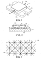
- Fig. 1 shows an appearance of a semiconductor package 1 which is a component for mounting a heating element applied to an attaching structure of a component for mounting a heating element relating to an embodiment of the present invention.
- the base plate 10 is formed in a rectangular shape, for example, and the attaching recesses 16 are formed at both ends thereof.
- the frame body 11 composing an element storage portion is installed integrally. Further, the other surface of the base plate 10 composes the attaching surface 10A to which a heat radiation member is attached.
- connection terminals 14 for external connection which are electrically connected to the semiconductor element 12 are respectively projected so as to connect external.
- the base plate 10, frame body 11, and lid body 13 are formed by metallic materials having excellent heat conductivity such as copper. Further, on the overall surface of the attaching surface 10A of the base plate 10, for example, a plurality of projections 15 in a quadrangular pyramid shape are formed closely (refer to Fig. 3 ).
- the attaching recesses 16 enables an inrorted-through screw member (not shown) to screw the heat radiation member 17, for example, in the state that the semiconductor package 1 is mounted on the heat radiation member 17 via the heat conduction sheet 18 (refer to Fig. 2 ).
- the heat radiation member 17 is, for example, a heat sink composed of a metallic body and has the attaching surface 17A to which the component for mounting the heating element (the semiconductor package 1) is attached.
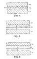
- the heat conduction sheet 18 is formed by a metallic material such as gold (Au), tin (Sn), or indium (In) or a material such as a graphite sheet or a highly polymerized heat conduction material which are softer than copper and are excellent in heat conductivity.
- the thickness of the heat conduction sheet 18 is set so that the heat conduction sheet 18 and the heat radiation member 17 may be adhered closely to each other in the state that the plurality of projections 15 of the base plate 10 are pushed into the heat conduction sheet 18.
- the base plate 10 is pressurized to one surface of the heat conduction sheet 18.
- the heat conduction sheet 18 and heat radiation member 17 are adhered closely to each other in the state that the plurality of projections 15 of the base plate 10 are pushed into the heat conduction sheet 18 (refer to Fig. 4 ).
- the base plate 10 incorporating the semiconductor element 12, as shown in Fig. 2 is put on the heat radiation member 17 via the heat conduction sheet 18 and is joined and attached to the heat radiation member 17 using the screw member (not shown). Then, the plurality of projections 15, as shown in Fig. 4 , make contact with and are pressed to one surface of the heat conduction sheet 18 and are pushed into the surface of the heat conduction sheet 18, thus the base of the plurality of projections 15 is adhered closely to one surface of the heat conduction sheet 18. By doing this, the base plate 10 is thermally coupled with the heat radiation member 17 via the heat conduction sheet 18.
- the heat transfer area (contact area) between the base plate 10 and the heat conduction sheet 18 is the area of the portion including the surfaces of the plurality of projections 15 of the attaching surface 10A of the base plate 10, which is larger than the area of the attaching surface.
- the heat transferred from the semiconductor element 12 to the base plate 10 is transferred efficiently from the portion including the surfaces of the plurality of projections 15 of the attaching surface to the heat conduction sheet 18, is led furthermore to the heat radiation member 17 via the heat conduction sheet 18, and then is radiated. Thereby, the semiconductor element 12 is controlled in heat.
- the heat conduction sheet 18 is formed by a metallic material, the heat transfer area between and the heat conduction sheet 18 and the base plate 10 is increased and furthermore the electric conduction blocking of the base plate 10 can be kept small. Therefore, the semiconductor element 12 mounted on the base plate 10 can keep a higher-performance in electric property.
- the base plate 10 is equipped with the plurality of projections 15 formed on the attaching surface 10A, and the base plate 10 is attached to the heat radiation member 17 via the heat conduction sheet 18 formed by a softer material than that of the base plate 10.
- the attaching structure of the component for mounting the heating element mentioned above can improve the heat radiation efficiency while downsizing of the base plate 10 is secured.
- the present invention is not limited to it and the projections formed on the attaching surface of the base plate 10 can be formed in various shapes such as the polygonal pyramid shape including a triangular pyramid and higher, conical shape, curved shape, needle shape, and ring shape and similar effective good results are expected.
- a plurality of projections 151 projected in a curved shape as shown in Fig. 5 a plurality of projections 152 in a circular ring shape as shown in Fig. 6 , or a plurality of projections 153 in a rectangular ring shape as shown in Fig. 7 may be installed.
- the present invention is not limited to the embodiment aforementioned and can be structured as shown in Figs- 8 to 13 and similar effective good results are expected. Hereinafter, those embodiments will be explained. However, for each of the embodiments shown in Figs. 8 to 13 , the same numerals are assigned to the same portions as the those shown in Figs. 1 to 4 and the detailed explanation will be omitted.
- the base plate 10 is equipped with a plurality of projections 154, for example, in the quadrangular pyramid shape on the attaching surface.
- the heat radiation member 17 is equipped with a plurality of projections 171, for example, in the quadrangular pyramid shape on the attaching surface to which the base plate 10 is attached-
- the heat conduction sheet 18 is held between the plurality of projections 154 and 171 of the base plate 10 and heat radiation member 17.
- the heat conduction sheet 18 is formed by a softer material than the materials of both base plate 10 and heat radiation member 17.
- the heat conduction sheet 18 is put on the plurality of projections 171 of the heat radiation member 17 and the plurality of projections 154 of the base plate 10 are put thereon. And, as mentioned above, the base plate 10 is attached to the heat radiation member 17 by the screw member (not shown). By doing this, the heat conduction sheet 18 is adhered closely to the base plate 10 and heat radiation member 17 between them in the state that the plurality of projections 154 and 171 of the two are pushed in both surfaces of the heat conduction sheet 18.
- the heat transfer area between the attaching surface of the base plate 10 and the heat conduction sheet 18 is the area of the attaching surface including the surface area including the outer peripheral walls of the plurality of projections 154. Further, the heat transfer area between the attaching surface of the heat radiation member 17 and the heat conduction sheet 18 is the area of the attaching surface including the surface area including the outer peripheral walls of the plurality of projections 171.
- the heat transfer areas are larger than the respective areas of the attaching surface of the base plate 10 and the attaching surface of the heat transfer member 17- Therefore, according to the attaching structure of the component for mounting the heating element, the heat conduction property between the part base plate 10 and the heat conduction sheet 18 and the heat conduction property between the heat conduction sheet 18 and the heat radiation member 17 are improved and better heat conduction properties can be obtained.
- the heat conduction sheet 18 is formed by a harder material than the materials of the base plate 10 and heat radiation member 17- On both surfaces of the heat conduction sheet 18, for example, a plurality of projections 181 and 182 in the quadrangular pyramid shape are formed in correspondence to and opposite to the attaching surface of the base plate 10 and the attaching surface of the heat radiation member 17.
- the heat conduction sheet 18 is arranged between the base plate 10 and the heat radiation member 17, and the base plate 10 and the heat radiation member 17 are attached by the screw member (not shown). Then, the heat conduction sheet 18 is adhered closely to the base plate 10 and heat radiation member 17 therebetween in the state that the plurality of projections 181 and 182 of both surfaces of the heat conduction sheet 18 make contact with the attaching surface of the base plate 10 and the attaching surface of the heat radiation member 17 and are pushed respectively into them.
- the heat transfer area between the attaching surface of the base plate 10 and the heat conduction sheet 18 is the area of the attaching surface including the surface area including the outer peripheral walls of the plurality of projections 181 of the heat conduction sheet 18.
- the heat transfer area between the attaching surface of the heat radiation member 17 and the heat conduction sheet 18 is the area of the attaching surface including the surface area including the outer peripheral walls of the plurality of projections 182 of the heat conduction sheet 18.
- the heat transfer areas are larger than the respective areas of the attaching surface of the base plate 10 and the attaching surface of the heat radiation member 17 and good heat conduction properties can be obtained-Embodiment 4
- a plurality of projections 155 and 172 in the quadrangular pyramid shape are formed on the attaching surface of the base plate 10 and the attaching surface of the heat radiation member 17, respectively. Further, a plurality of projections 183 and 184 in the quadrangular pyramid shape, for example, are formed on both surfaces of the heat conduction sheet 18 in correspondence to the plurality of projections 155 and 172 of the base plate 10 and heat radiation member 17.
- the heat conduction sheet 18 is put on the heat radiation member 17 so that the plurality of projections 184 on one surface of the heat conduction sheet 18 may be fit into the plurality of projections 172 of the heat radiation member 17 so as to mate with each other. Further, the base plate 10 is put on the heat conduction sheet 18 so that the plurality of projections 155 of the base plate 10 may be fit into the plurality of projections 183 of the other surface of the heat conduction sheet 18 so as to mate with each other.
- the heat conduction sheet 18 is adhered closely to the base plate 10 and heat radiation member 17 between them in the state that the plurality of projections 184 and 183 of both surfaces of the heat conduction sheet 18 mate with the plurality of projections 172 and 155 of the heat radiation member 17 and base plate 10.
- the heat transfer area of the heat conduction sheet 18 on the attaching surface of the base plate 10 is the area of the attaching surface including the surface area including the outer peripheral walls of the plurality of projections 155.
- the heat transfer area of the heat conduction sheet 18 on the attaching surface of the heat radiation member 17 is the area of the attaching surface including the surface area including the outer peripheral walls of the plurality of projections 172.
- the heat transfer areas are larger than the respective areas of the attaching surface of the base plate 10 and the attaching surface of the heat transfer member 17 and good heat conduction properties can be obtained.
- a plurality of projections 156 and 173 in the quadrangular pyramid shape are formed on the attaching surface of the base plate 10 and the attaching surface of the heat radiation member 17, respectively.
- the base plate 10 is attached and adhered closely to the heat radiation member 17 by the screw member (not shown) in the state that the plurality of projections 156 of the base plate 10 are fit into the plurality of projections 173 of the heat radiation member 17 so as to mate with each other.
- the attaching surface of the base plate 10 is adhered closely and thermally coupled to the attaching surface of the heat radiation member 17.
- the heat transfer area of the base plate 10 to the heat radiation member 17 is the area of the attaching surface including the surface area including the outer peripheral walls of the plurality of projections 156.
- the heat transfer area is larger than the area of the attaching surface, so that a good heat conduction property can be obtained.
- the heat radiation member 17 includes a plurality of projections 174 formed on the attaching surface and the base plate 10 is attached to the heat radiation member 17 via the heat conduction sheet 18 formed by a softer material than that of the heat radiation member 17.
- the plurality of projections 174 of the attaching surface of the heat radiation member 17 are pushed into the heat conduction sheet 18 and the base plate 10 is thermally coupled with the heat radiation member 17 via the heat conduction sheet 18.
- the heat transfer area between the heat radiation member 17 and the heat conduction sheet 18 is spread more than the area of the attaching surface of the heat radiation member 17 due to the surfaces of the plurality of projections 174, thus the heat conduction property between the heat radiation member 17 and the heat conduction sheet 18 can be improved.
- downsizing of the base plate 10 is secured and the heat radiation efficiency can be improved.
- the component for mounting the heating element 20 with an L-shaped section is attached to the heat radiation member 17 via the heat conduction sheet 18.
- the component for mounting the heating element 20 is attached to the heat radiation member 17 by the screw member (not shown).
- the component for mounting the heating element 20 and heat radiation member 17 include, similarly to the embodiment shown in Fig. 8 , a plurality of projections (not shown) formed respectively on the attaching surfaces 20A, 17A thereof.
- the heat conduction sheet 18 is composed of a softer material than those of the component for mounting the heating element 20 and heat radiation member 17.
- the heat radiation member 17 has a plurality of heat radiation fins 17C formed on a base body 17B.
- the heating element 22 is mounted, for example, on a portion 202 which is different from an attaching portion 201 which the component for mounting the heating element 20 is attached to the heat radiation member 17.
- the heating element 22 may be mounted to the component for mounting the heating element 20 before attaching the component for mounting the heating element 20 to the heat radiation member 17 or after attaching the component for mounting the heating element 20 to the heat radiation member 17.
- the shapes of the plurality of projections 154 (155, 156), 171 (172, 173), 181, 182 (183, 184), and 174 are not limited to the quadrangular pyramid shape, and various shapes such as the polygonal pyramid shape including a triangular pyramid and higher, conical shape, curved shape, needle shape, and ring shape may be used, and similar effective good results are expected.
- the present invention is not limited to it and a component for mounting a heating element mounting various electronic parts as a heating element can be applied and effective good results can be expected similarly.
- the present invention is not limited to the embodiments aforementioned and can be modified variously within a scope of the invention at the practice stage.
- the embodiments aforementioned include the inventions at various stages and various inventions can be extracted by an appropriate combination of a plurality of disclosed constituent elements.
- the attaching structure of the component for mounting the heating element of the present invention can spread the heat transfer area of the attaching surface of the component for mounting the heating element or the heat radiation member, and can be applied to a use of mounting of the heating element required to have a high heat radiation efficiency.
Abstract
Description
- The present invention relates to an attaching structure of a component for mounting a heating element to mount a heating element such as a semiconductor element composing various electronic parts.
- Generally, a semiconductor apparatus is structured so that a semiconductor element composing an electronic part which is a heating element is stored and arranged in a semiconductor package which is a component for mounting a heating element and a connection terminal for external connection is protruded from the peripheral wall of the semiconductor package. Such a semiconductor package is used in the state that the connection terminal for external connection is electrically connected to a circuit of a printed circuit board. If the semiconductor element generates heat and rises in temperature due to the use of the semiconductor package, a reduction in the performance of the semiconductor element is caused. Therefore, the semiconductor package uses a method for discharging externally generated heat and keeping the temperature of the semiconductor element at the allowable value.
- Therefore, for the semiconductor package, various cooling structures for efficiently discharging the heat with the use and thermally controlling the temperature of the semiconductor element to the allowable value have been developed. As such a cooling structure, a structure is proposed that the package base body is attached to a heat radiator via a graphite sheet having an excellent heat conduction efficiency, for example, thus the heat can be transferred highly efficiently (for example, refer to Patent Document 1). Further, there is another constitution available that instead of the graphite sheet, heat radiation grease is coated between the package base body and the heat radiator.
- Patent Document 1: Japanese Patent Application disclosure
2004-288949 - In the semiconductor package constitution aforementioned, the graphite sheet or heat radiation grease is arranged between attaching surfaces of the heat radiator and package base body, so that the efficiency of heat conduction can be improved. However, a problem arises that the graphite sheet and heat radiation grease cause blocking the electric conduction and a reduction in the electric performance. Further, the heat conduction efficiency between the package base body and heat radiator is decided by heat transfer areas between the package base body and the graphite sheet and between the heat radiator and the graphite sheet. Therefore, in order to further improve the heat conduction efficiency, the heat transfer area must be increased, thus a problem arises that the package base body becomes large.
- Such a situation is not limited to the semiconductor package and is the same also to the various component for mounting the heating element on which a heating element such as an electronic part is mounted.
- The present invention was developed in view of the above-mentioned situation and is intended to provide an attaching structure of a component for mounting a heating element of which heat radiation efficiency is improved by improving the heat conduction efficiency while downsizing of the component for mounting the heating element is maintained.
- An attaching structure of a component for mounting a heating element relating to the embodiments of the present invention incudes the component for mounting the heating element having a attaching surface with a plurality of projections arranged and mounting a. heating element, a heat radiation member to which the component for mounting the heating element is thermally coupled and attached, and a heat conduction sheet which is formed by a softer material than that of the component for mounting the heating element and is arranged between the attaching surface of the component for mounting the heating element and the heat radiation member.
- According to the attaching structure of the component for mounting the heating element mentioned above, the component for mounting the heating element is thermally coupled with the heat radiation member via the heat conduction sheet, attached and arranged in the state that the attaching surface of the component for mounting the heating element is opposite to the heat radiation member via the heat conduction sheet and the plurality of projections are pushed into the heat conduction sheet which is materially soft.
- By doing this, the heat transfer area (contact area) between the component for mounting the heating element and the heat conduction sheet is added with the surface area including the outer peripheral walls of the plurality of projections of the attaching surface, thereby can be spread without increasing the area (projected area) of the attaching surface itself. Therefore, the heat transfer area can be increased and the heat radiation efficiency can be improved, while downsizing of the component for mounting the heating element is maintained.
- As mentioned above, according to the present invention, an attaching structure of a component for mounting a heating element which improves the heat radiation efficiency while downsizing of the component for mounting the heating element is maintained can be provided.
-
-
Fig. 1 is a perspective view showing the external constitution of a semiconductor package to which an attaching structure of a component for mounting a heating element relating to an embodiment of the present invention is applied. -
Fig. 2 is a cross sectional view showing the state that the semiconductor package shown inFig. 1 is attached to the heat radiation member. -
Fig. 3 is a plan view showing an enlarged part of the attaching surface of a base plate shown inFig. 1 . -
Fig. 4 is a cross sectional view of a main section showing an enlarged part ofFig. 2 . -
Fig. 5 is a cross sectional view of a main section shown for explaining an attaching structure of a component for mounting a heating element relating to another embodiment of the present invention. -
Fig. 6 is a cross sectional view of a main section shown for explaining an attaching structure of a component for mounting a heating element relating to still another embodiment of the present invention. -
Fig. 7 is a cross sectional view of a main section shown for explaining an attaching structure of a component for mounting a heating element relating to a further embodiment of the present invention. -
Fig. 8 is a cross sectional view of the main section shown for explaining an attaching structure of a component for mounting a heating element relating to a still further embodiment of the present invention. -
Fig. 9 is a cross sectional view of a main section shown for explaining an attaching structure of a component for mounting a heating element relating to yet a further embodiment of the present invention. -
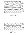
Fig. 10 is a cross sectional view of a main section shown for explaining an attaching structure of a component for mounting a heating element relating to yet a further embodiment of the present invention. -
Fig. 11 is a cross sectional view of a main section showing for explaining an attaching structure of a component for mounting a heating element relating to yet a. further embodiment of the present invention. -
Fig. 12 is a cross sectional view of a main section shown for explaining an attaching structure of a component for mounting a heating element relating to yet a further embodiment of the present invention. -
Fig. 13 is a cross sectional view of a main section shown for explaining an attaching structure of a component for mounting a heating element relating to yet a further embodiment of the present invention. -
- 10
- Base plate
- 11 10A
- Attacbing surface Frame body
- 12
- Semiconductor element
- 13
- Lid body
- 14
- Connection terminal for external connection
- 15, 51, 152, 153, 154, 155, 156
- Projection
- 16
- Attaching recess
- 17
- Heat radiation member
- 17A
- Attaching surface
- 18
- Heat conduction sheet
- 20
- Component for mounting heating element
- 22
- Heating element
- 171, 172, 173, 174
- Projection
- 181, 182, 183, 184
- Projection
- Hereinafter, an attaching structure of a component for mounting a heating element relating to the embodiments of the present invention will be explained in detail with reference to the accompanying drawings.
-
Fig. 1 shows an appearance of a semiconductor package 1 which is a component for mounting a heating element applied to an attaching structure of a component for mounting a heating element relating to an embodiment of the present invention. Thebase plate 10 is formed in a rectangular shape, for example, and the attachingrecesses 16 are formed at both ends thereof. On one surface of thebase plate 10, theframe body 11 composing an element storage portion is installed integrally. Further, the other surface of thebase plate 10 composes the attachingsurface 10A to which a heat radiation member is attached. - On the
base plate 10 in theframe body 11, as shown inFig. 2 , the semiconductor element 72 is mounted, and on theframe body 11, thelid body 13 is attached. On both side walls of theframe body 11 which are opposite to each other, theconnection terminals 14 for external connection which are electrically connected to thesemiconductor element 12 are respectively projected so as to connect external. - The
base plate 10,frame body 11, andlid body 13 are formed by metallic materials having excellent heat conductivity such as copper. Further, on the overall surface of the attachingsurface 10A of thebase plate 10, for example, a plurality ofprojections 15 in a quadrangular pyramid shape are formed closely (refer toFig. 3 ). - The attaching recesses 16 enables an inrorted-through screw member (not shown) to screw the
heat radiation member 17, for example, in the state that the semiconductor package 1 is mounted on theheat radiation member 17 via the heat conduction sheet 18 (refer toFig. 2 ). Theheat radiation member 17 is, for example, a heat sink composed of a metallic body and has the attachingsurface 17A to which the component for mounting the heating element (the semiconductor package 1) is attached. - When the
base plate 10 is, for example, formed by copper, theheat conduction sheet 18 is formed by a metallic material such as gold (Au), tin (Sn), or indium (In) or a material such as a graphite sheet or a highly polymerized heat conduction material which are softer than copper and are excellent in heat conductivity. The thickness of theheat conduction sheet 18 is set so that theheat conduction sheet 18 and theheat radiation member 17 may be adhered closely to each other in the state that the plurality ofprojections 15 of thebase plate 10 are pushed into theheat conduction sheet 18. - If the screw member is inserted through the attaching
recesses 16 of thebase plate 10 and is screwed with theheat radiation member 17, thebase plate 10 is pressurized to one surface of theheat conduction sheet 18. By doing this, theheat conduction sheet 18 andheat radiation member 17 are adhered closely to each other in the state that the plurality ofprojections 15 of thebase plate 10 are pushed into the heat conduction sheet 18 (refer toFig. 4 ). - By use of this constitution, the
base plate 10 incorporating thesemiconductor element 12, as shown inFig. 2 , is put on theheat radiation member 17 via theheat conduction sheet 18 and is joined and attached to theheat radiation member 17 using the screw member (not shown). Then, the plurality ofprojections 15, as shown inFig. 4 , make contact with and are pressed to one surface of theheat conduction sheet 18 and are pushed into the surface of theheat conduction sheet 18, thus the base of the plurality ofprojections 15 is adhered closely to one surface of theheat conduction sheet 18. By doing this, thebase plate 10 is thermally coupled with theheat radiation member 17 via theheat conduction sheet 18. - Here, the heat transfer area (contact area) between the
base plate 10 and theheat conduction sheet 18 is the area of the portion including the surfaces of the plurality ofprojections 15 of the attachingsurface 10A of thebase plate 10, which is larger than the area of the attaching surface. The heat transferred from thesemiconductor element 12 to thebase plate 10 is transferred efficiently from the portion including the surfaces of the plurality ofprojections 15 of the attaching surface to theheat conduction sheet 18, is led furthermore to theheat radiation member 17 via theheat conduction sheet 18, and then is radiated. Thereby, thesemiconductor element 12 is controlled in heat. - When the
heat conduction sheet 18 is formed by a metallic material, the heat transfer area between and theheat conduction sheet 18 and thebase plate 10 is increased and furthermore the electric conduction blocking of thebase plate 10 can be kept small. Therefore, thesemiconductor element 12 mounted on thebase plate 10 can keep a higher-performance in electric property. - In the aforementioned attaching structure of the component for mounting the heating element, the
base plate 10 is equipped with the plurality ofprojections 15 formed on the attachingsurface 10A, and thebase plate 10 is attached to theheat radiation member 17 via theheat conduction sheet 18 formed by a softer material than that of thebase plate 10. - Therefore, if the
base plate 10 is attached to theheat radiation member 17 on the attaching surface via theheat conduction sheet 18, the plurality ofprojections 15 of the attaching surface are pushed into theheat conduction sheet 18 and thebase plate 10 is thermally coupled with theheat radiation member 17 via theheat conduction sheet 18. The heat transfer area between thebase plate 10 and theheat conduction sheet 18 is the area of the attaching surface including the surface area including the outer peripheral walls of the plurality ofprojections 15, and the heat transfer area can be increased without increasing the area of the attaching surface of thebase plate 10. As a result, the attaching structure of the component for mounting the heating element mentioned above can improve the heat radiation efficiency while downsizing of thebase plate 10 is secured. - In the embodiment aforementioned, the case that the plurality of
projections 15 in the quadrangular pyramid shape is formed on the attaching surface of thebase plate 10 is explained. However, the present invention is not limited to it and the projections formed on the attaching surface of thebase plate 10 can be formed in various shapes such as the polygonal pyramid shape including a triangular pyramid and higher, conical shape, curved shape, needle shape, and ring shape and similar effective good results are expected. - On the attaching surface of the
base plate 10, for example, a plurality ofprojections 151 projected in a curved shape as shown inFig. 5 , a plurality ofprojections 152 in a circular ring shape as shown inFig. 6 , or a plurality ofprojections 153 in a rectangular ring shape as shown inFig. 7 may be installed. - The present invention is not limited to the embodiment aforementioned and can be structured as shown in Figs- 8 to 13 and similar effective good results are expected. Hereinafter, those embodiments will be explained. However, for each of the embodiments shown in
Figs. 8 to 13 , the same numerals are assigned to the same portions as the those shown inFigs. 1 to 4 and the detailed explanation will be omitted. - In the embodiment shown in
Fig. 8 , thebase plate 10 is equipped with a plurality ofprojections 154, for example, in the quadrangular pyramid shape on the attaching surface. Further, theheat radiation member 17 is equipped with a plurality ofprojections 171, for example, in the quadrangular pyramid shape on the attaching surface to which thebase plate 10 is attached- And, theheat conduction sheet 18 is held between the plurality ofprojections base plate 10 andheat radiation member 17. In this embodiment, theheat conduction sheet 18 is formed by a softer material than the materials of bothbase plate 10 andheat radiation member 17. - The
heat conduction sheet 18 is put on the plurality ofprojections 171 of theheat radiation member 17 and the plurality ofprojections 154 of thebase plate 10 are put thereon. And, as mentioned above, thebase plate 10 is attached to theheat radiation member 17 by the screw member (not shown). By doing this, theheat conduction sheet 18 is adhered closely to thebase plate 10 andheat radiation member 17 between them in the state that the plurality ofprojections heat conduction sheet 18. - As a result, the heat transfer area between the attaching surface of the
base plate 10 and theheat conduction sheet 18 is the area of the attaching surface including the surface area including the outer peripheral walls of the plurality ofprojections 154. Further, the heat transfer area between the attaching surface of theheat radiation member 17 and theheat conduction sheet 18 is the area of the attaching surface including the surface area including the outer peripheral walls of the plurality ofprojections 171. The heat transfer areas are larger than the respective areas of the attaching surface of thebase plate 10 and the attaching surface of the heat transfer member 17- Therefore, according to the attaching structure of the component for mounting the heating element, the heat conduction property between thepart base plate 10 and theheat conduction sheet 18 and the heat conduction property between theheat conduction sheet 18 and theheat radiation member 17 are improved and better heat conduction properties can be obtained. - Further, in the embodiment shown in
Fig. 9 , theheat conduction sheet 18 is formed by a harder material than the materials of thebase plate 10 and heat radiation member 17- On both surfaces of theheat conduction sheet 18, for example, a plurality ofprojections base plate 10 and the attaching surface of theheat radiation member 17. - The
heat conduction sheet 18 is arranged between thebase plate 10 and theheat radiation member 17, and thebase plate 10 and theheat radiation member 17 are attached by the screw member (not shown). Then, theheat conduction sheet 18 is adhered closely to thebase plate 10 andheat radiation member 17 therebetween in the state that the plurality ofprojections heat conduction sheet 18 make contact with the attaching surface of thebase plate 10 and the attaching surface of theheat radiation member 17 and are pushed respectively into them. - As a result, the heat transfer area between the attaching surface of the
base plate 10 and theheat conduction sheet 18 is the area of the attaching surface including the surface area including the outer peripheral walls of the plurality ofprojections 181 of theheat conduction sheet 18. Further, the heat transfer area between the attaching surface of theheat radiation member 17 and theheat conduction sheet 18 is the area of the attaching surface including the surface area including the outer peripheral walls of the plurality ofprojections 182 of theheat conduction sheet 18. The heat transfer areas are larger than the respective areas of the attaching surface of thebase plate 10 and the attaching surface of theheat radiation member 17 and good heat conduction properties can be obtained-Embodiment 4 - In the embodiment shown in
Fig. 10 , a plurality ofprojections 155 and 172 in the quadrangular pyramid shape, for example, are formed on the attaching surface of thebase plate 10 and the attaching surface of theheat radiation member 17, respectively. Further, a plurality ofprojections heat conduction sheet 18 in correspondence to the plurality ofprojections 155 and 172 of thebase plate 10 andheat radiation member 17. - The
heat conduction sheet 18 is put on theheat radiation member 17 so that the plurality ofprojections 184 on one surface of theheat conduction sheet 18 may be fit into the plurality ofprojections 172 of theheat radiation member 17 so as to mate with each other. Further, thebase plate 10 is put on theheat conduction sheet 18 so that the plurality of projections 155 of thebase plate 10 may be fit into the plurality ofprojections 183 of the other surface of theheat conduction sheet 18 so as to mate with each other. And, if thebase plate 10 is attached to theheat radiation member 17 by the screw member (not shown) as mentioned above, theheat conduction sheet 18 is adhered closely to thebase plate 10 andheat radiation member 17 between them in the state that the plurality ofprojections heat conduction sheet 18 mate with the plurality ofprojections 172 and 155 of theheat radiation member 17 andbase plate 10. - As a result, the heat transfer area of the
heat conduction sheet 18 on the attaching surface of thebase plate 10 is the area of the attaching surface including the surface area including the outer peripheral walls of the plurality of projections 155. Further, the heat transfer area of theheat conduction sheet 18 on the attaching surface of theheat radiation member 17 is the area of the attaching surface including the surface area including the outer peripheral walls of the plurality ofprojections 172. The heat transfer areas are larger than the respective areas of the attaching surface of thebase plate 10 and the attaching surface of theheat transfer member 17 and good heat conduction properties can be obtained. - In the embodiment shown in
Fig. 11 , a plurality ofprojections base plate 10 and the attaching surface of theheat radiation member 17, respectively. Thebase plate 10 is attached and adhered closely to theheat radiation member 17 by the screw member (not shown) in the state that the plurality ofprojections 156 of thebase plate 10 are fit into the plurality ofprojections 173 of theheat radiation member 17 so as to mate with each other. - Thereby, the attaching surface of the
base plate 10 is adhered closely and thermally coupled to the attaching surface of theheat radiation member 17. - As a result, the heat transfer area of the
base plate 10 to theheat radiation member 17 is the area of the attaching surface including the surface area including the outer peripheral walls of the plurality ofprojections 156. The heat transfer area is larger than the area of the attaching surface, so that a good heat conduction property can be obtained. - In the embodiment shown in
Fig. 12 , theheat radiation member 17 includes a plurality ofprojections 174 formed on the attaching surface and thebase plate 10 is attached to theheat radiation member 17 via theheat conduction sheet 18 formed by a softer material than that of theheat radiation member 17. - By doing this, the plurality of
projections 174 of the attaching surface of theheat radiation member 17 are pushed into theheat conduction sheet 18 and thebase plate 10 is thermally coupled with theheat radiation member 17 via theheat conduction sheet 18. The heat transfer area between theheat radiation member 17 and theheat conduction sheet 18 is spread more than the area of the attaching surface of theheat radiation member 17 due to the surfaces of the plurality ofprojections 174, thus the heat conduction property between theheat radiation member 17 and theheat conduction sheet 18 can be improved. As a result, in the attaching structure of the component for mounting the heating element, downsizing of thebase plate 10 is secured and the heat radiation efficiency can be improved. - In the embodiment shown in
Fig. 13 , the component for mounting theheating element 20 with an L-shaped section is attached to theheat radiation member 17 via theheat conduction sheet 18. Similarly to the other embodiments aforementioned, the component for mounting theheating element 20 is attached to theheat radiation member 17 by the screw member (not shown). The component for mounting theheating element 20 andheat radiation member 17 include, similarly to the embodiment shown inFig. 8 , a plurality of projections (not shown) formed respectively on the attachingsurfaces heat conduction sheet 18 is composed of a softer material than those of the component for mounting theheating element 20 andheat radiation member 17. Theheat radiation member 17 has a plurality ofheat radiation fins 17C formed on abase body 17B. - Further, the
heating element 22 is mounted, for example, on aportion 202 which is different from an attachingportion 201 which the component for mounting theheating element 20 is attached to theheat radiation member 17. Theheating element 22 may be mounted to the component for mounting theheating element 20 before attaching the component for mounting theheating element 20 to theheat radiation member 17 or after attaching the component for mounting theheating element 20 to theheat radiation member 17. By use of the attaching structure of the component for mounting the heating element, the attaching structure of the component for mounting the heating element with the heat radiation efficiency improved can be obtained. - Further, in the embodiment shown in
Figs. 8 to 13 , the shapes of the plurality of projections 154 (155, 156), 171 (172, 173), 181, 182 (183, 184), and 174 are not limited to the quadrangular pyramid shape, and various shapes such as the polygonal pyramid shape including a triangular pyramid and higher, conical shape, curved shape, needle shape, and ring shape may be used, and similar effective good results are expected. - Further, in the embodiments 1 to 6, the case that the component for mounting the heating element is applied to the semiconductor package is explained. However, the present invention is not limited to it and a component for mounting a heating element mounting various electronic parts as a heating element can be applied and effective good results can be expected similarly.
- Accordingly, the present invention is not limited to the embodiments aforementioned and can be modified variously within a scope of the invention at the practice stage. Furthermore, the embodiments aforementioned include the inventions at various stages and various inventions can be extracted by an appropriate combination of a plurality of disclosed constituent elements.
- For example, even if some constituent elements are deleted from the whole constituent elements indicated in the embodiments, when the problems described in the column of "Problems to be Solved by the Invention" can be solved and the effects described in the column of "Effects of the Invention" can be obtained, the constitution with the constituent elements deleted can be extracted as an invention.
- The attaching structure of the component for mounting the heating element of the present invention can spread the heat transfer area of the attaching surface of the component for mounting the heating element or the heat radiation member, and can be applied to a use of mounting of the heating element required to have a high heat radiation efficiency.
Claims (11)
- An attaching structure of a component for mounting a heating element comprising:a component for mounting a heating element to mount a heating element, the component for mounting the heating element having an attaching surface with a plurality of projections;a heat radiation member thermally coupled to the component for mounting the heating element; anda heat conduction sheet formed by a softer material than that of the component for mounting the heating element and arranged between the attaching surface of the component for mounting the heating element and the heat radiation member.
- The attaching structure of the component for mounting the heating element according to claim 1, wherein the plurality of projections of the component for mounting the heating element are installed overall the attaching surface.
- An attaching structure of a component for mounting a heating element comprisinga component for mounting a heating element to mount a heating element, the component for mounting the heating element having an attaching surface with a plurality of projections;a heat radiation member having an attaching surface with a plurality of projections and thermally coupled to the component for mounting the heating element; anda heat conduction sheet arranged between the plurality of projections of the component for mounting the heating element and the plurality of projections of the heat radiation member, and formed by a softer material than those of the component for mounting the heating element and the heat radiation member.
- An attaching structure of a component for mounting a heating element comprising:a component for mounting a heating element to mount a heating element, the component for mounting the heating element having a attaching surface;a heat radiation member having a attaching surface and thermally coupled to the attaching surface of the component for mounting the heating element; anda heat conduction sheet arranged between the component for mounting the heating element and the heat radiation member, and formed by a harder material than those of the component for mounting the heating element and the heat radiation member, and the heat conduction sheet having a plurality of projections formed on both surfaces to face to the attaching surface of the component for mounting the heating element and the attaching surface of the heat radiation member.
- An attaching structure of a component for mounting a heating element comprising:a component for mounting a heating element to mount a heating element, the component for mounting the heating element having an attaching surface with a plurality of projections;a heat radiation member having an attaching surface with a plurality of projections and thermally coupled to the attaching surface of the component for mounting the heating element; anda heat conduction sheet arranged between the attaching surface of the component for mounting the heating element and the attaching surface of the heat radiation member, and having a plurality of projections fit to the plurality of projections of the component for mounting the heating element and the plurality of projections of the heat radiation member.
- The attaching structure of the component for mounting the heating element according to claim 5, wherein the plurality of projections of the component for mounting the heating element are installed overall the attaching surface of the component for mounting the heating element, the plurality of projections of the heat radiation member are installed overall the attaching surface of the heat radiation member, and the plurality of projections of the heat conduction sheet are installed overall both surfaces of the heat conduction sheet.
- An attaching structure of a component for mounting a heating element comprising:a component for mounting a heating element to mount a heating element, the component for mounting the heating element having an attaching surface with a plurality of projections; anda heat radiation member having an attaching surface with a plurality of projections and thermally coupled to the component for mounting the heating element, and the plurality of projections of the component for mounting the heating element being fit with the plurality of projections of the heat radiation member.
- The attaching structure of the component for mounting the heating element according to claim 7, wherein the plurality of projections of the component for mounting the heating element and the plurality of projections of the heat radiation member are installed overall the respective attaching surfaces.
- An attaching structure of a component for mounting a heating element comprising:a component for mounting a heating element to mount a heating element, the component for mounting the heating element having a attaching surface;a heat radiation member having a attaching surface with a plurality of projections and thermally coupled to the component for mounting the heating element; anda heat conduction sheet arranged between the component for mounting the heating element and the heat radiation member and being formed by a softer material than that of the heat radiation member.
- The attaching structure of the component for mounting the heating element according to any one of claims 1, 3, 4, 5, and 9, wherein the heat conduction sheet is formed by a metallic material.
- The attaching structure of the component for mounting the heating element according to any one of claims 1, 3, 4, 5, 7, and 9, wherein the component for mounting the heating element is a semiconductor package.
Applications Claiming Priority (2)
| Application Number | Priority Date | Filing Date | Title |
|---|---|---|---|
| JP2008055438A JP2009212390A (en) | 2008-03-05 | 2008-03-05 | Attachment structure of heating element mounted component |
| PCT/JP2008/003685 WO2009110045A1 (en) | 2008-03-05 | 2008-12-10 | Structure for attaching component having heating body mounted thereon |
Publications (2)
| Publication Number | Publication Date |
|---|---|
| EP2251902A1 true EP2251902A1 (en) | 2010-11-17 |
| EP2251902A4 EP2251902A4 (en) | 2014-10-08 |
Family
ID=41055627
Family Applications (1)
| Application Number | Title | Priority Date | Filing Date |
|---|---|---|---|
| EP08873167.4A Withdrawn EP2251902A4 (en) | 2008-03-05 | 2008-12-10 | Structure for attaching component having heating body mounted thereon |
Country Status (5)
| Country | Link |
|---|---|
| US (1) | US20100186939A1 (en) |
| EP (1) | EP2251902A4 (en) |
| JP (1) | JP2009212390A (en) |
| KR (1) | KR20100025546A (en) |
| WO (1) | WO2009110045A1 (en) |
Families Citing this family (11)
| Publication number | Priority date | Publication date | Assignee | Title |
|---|---|---|---|---|
| JP4643703B2 (en) | 2008-11-21 | 2011-03-02 | 株式会社東芝 | Semiconductor device fixture and mounting structure thereof |
| JP5806464B2 (en) * | 2010-02-03 | 2015-11-10 | 株式会社東芝 | Semiconductor element storage package and semiconductor device using the same |
| JP2011222564A (en) * | 2010-04-02 | 2011-11-04 | Nec Personal Products Co Ltd | Heat sink, heat dissipation member, and electronic device |
| WO2011148662A1 (en) * | 2010-05-24 | 2011-12-01 | シャープ株式会社 | Heat dissipating structure of electronic apparatus |
| JP5831273B2 (en) * | 2012-02-09 | 2015-12-09 | 三菱電機株式会社 | Semiconductor device and manufacturing method thereof |
| DE112013001612B4 (en) | 2012-03-22 | 2022-05-12 | Mitsubishi Electric Corporation | Semiconductor component and method for its manufacture |
| DE112013007721B4 (en) * | 2013-12-27 | 2020-07-23 | Mitsubishi Electric Corporation | Semiconductor device |
| KR101734912B1 (en) * | 2015-03-02 | 2017-05-12 | 주식회사 엘엠에스 | Heat Spreader |
| JP6612723B2 (en) * | 2016-12-07 | 2019-11-27 | 株式会社東芝 | Board device |
| CN109219315B (en) * | 2018-09-04 | 2023-12-01 | 常州是为电子有限公司 | Case with semiconductor power device heat dissipation base and assembling method |
| US10825750B2 (en) * | 2018-11-13 | 2020-11-03 | Ge Aviation Systems Llc | Method and apparatus for heat-dissipation in electronics |
Citations (4)
| Publication number | Priority date | Publication date | Assignee | Title |
|---|---|---|---|---|
| JPS60145647A (en) * | 1984-01-10 | 1985-08-01 | Fujitsu Ltd | Heat-dissipation mounting method for heat generator module |
| JPH0672247U (en) * | 1991-11-26 | 1994-10-07 | サンケン電気株式会社 | Semiconductor device |
| JP2003273294A (en) * | 2002-01-09 | 2003-09-26 | Nitto Denko Corp | Thermal conductive sheet and semiconductor device using the same |
| WO2007007602A1 (en) * | 2005-07-07 | 2007-01-18 | Kabushiki Kaisha Toyota Jidoshokki | Heat dissipation device and power module |
Family Cites Families (9)
| Publication number | Priority date | Publication date | Assignee | Title |
|---|---|---|---|---|
| JP2758273B2 (en) | 1991-01-17 | 1998-05-28 | 富士通株式会社 | Mounting structure of high-frequency planar circuit module |
| JP4416362B2 (en) | 2000-10-30 | 2010-02-17 | 株式会社クボタ | Heat dissipation component for semiconductor element and semiconductor device |
| JP2002270745A (en) | 2001-03-12 | 2002-09-20 | Hitachi Cable Ltd | Heat radiating material with fin, and method for manufacturing the same |
| CN1242474C (en) * | 2001-07-09 | 2006-02-15 | 大金工业株式会社 | Power module and air conditioner |
| JP2004063898A (en) | 2002-07-30 | 2004-02-26 | Hitachi Cable Ltd | Heat radiating material and its manufacturing method |
| JP2006237103A (en) | 2005-02-23 | 2006-09-07 | Kyocera Corp | Thermally conductive member and electronic apparatus |
| US7893449B2 (en) * | 2005-12-14 | 2011-02-22 | Showa Denko K.K. | Gallium nitride based compound semiconductor light-emitting device having high emission efficiency and method of manufacturing the same |
| JP2008078564A (en) * | 2006-09-25 | 2008-04-03 | Fujikura Ltd | Heat dissipating structure |
| JP5083261B2 (en) * | 2009-03-26 | 2012-11-28 | 三菱電機株式会社 | Semiconductor device and manufacturing method thereof |
-
2008
- 2008-03-05 JP JP2008055438A patent/JP2009212390A/en active Pending
- 2008-12-10 WO PCT/JP2008/003685 patent/WO2009110045A1/en active Application Filing
- 2008-12-10 US US12/667,275 patent/US20100186939A1/en not_active Abandoned
- 2008-12-10 EP EP08873167.4A patent/EP2251902A4/en not_active Withdrawn
- 2008-12-10 KR KR1020097027401A patent/KR20100025546A/en not_active Application Discontinuation
Patent Citations (4)
| Publication number | Priority date | Publication date | Assignee | Title |
|---|---|---|---|---|
| JPS60145647A (en) * | 1984-01-10 | 1985-08-01 | Fujitsu Ltd | Heat-dissipation mounting method for heat generator module |
| JPH0672247U (en) * | 1991-11-26 | 1994-10-07 | サンケン電気株式会社 | Semiconductor device |
| JP2003273294A (en) * | 2002-01-09 | 2003-09-26 | Nitto Denko Corp | Thermal conductive sheet and semiconductor device using the same |
| WO2007007602A1 (en) * | 2005-07-07 | 2007-01-18 | Kabushiki Kaisha Toyota Jidoshokki | Heat dissipation device and power module |
Non-Patent Citations (1)
| Title |
|---|
| See also references of WO2009110045A1 * |
Also Published As
| Publication number | Publication date |
|---|---|
| WO2009110045A1 (en) | 2009-09-11 |
| US20100186939A1 (en) | 2010-07-29 |
| JP2009212390A (en) | 2009-09-17 |
| KR20100025546A (en) | 2010-03-09 |
| EP2251902A4 (en) | 2014-10-08 |
Similar Documents
| Publication | Publication Date | Title |
|---|---|---|
| EP2251902A1 (en) | Structure for attaching component having heating body mounted thereon | |
| US7023699B2 (en) | Liquid cooled metal thermal stack for high-power dies | |
| JP4279144B2 (en) | Power semiconductor module | |
| EP2738804B1 (en) | Flexible thermal transfer strips | |
| US20060180926A1 (en) | Heat spreader clamping mechanism for semiconductor modules | |
| US20170219303A1 (en) | Flexible metallic heat connector | |
| JPH10189839A (en) | Electronic package with compressible heat-sink structure and its manufacture | |
| US6590771B2 (en) | Heat sink assembly and method | |
| US10820406B2 (en) | Circuit structure and electrical junction box | |
| JP2008124468A (en) | Power module | |
| JP2015505172A (en) | LED module, LED unit, and luminaire including LED module | |
| US6917482B2 (en) | Optical module mounted body and securing method of optical module | |
| US20090229790A1 (en) | Radiating fin assembly for thermal module | |
| US20050225945A1 (en) | Universal mountable heat sink with integral spring clip | |
| JP4138634B2 (en) | Heat sink fixing device | |
| JP2713628B2 (en) | Heat dissipation structure of surface mount type IC package | |
| JP2004096034A (en) | Method of manufacturing module structure, circuit board and method of fixing the same | |
| JP2007035843A (en) | Electronic circuit device | |
| JP2013004642A (en) | Heat sink | |
| US7002804B2 (en) | Heat dissipating apparatus | |
| JP2002246081A (en) | Terminal block with temperature fuse connection contact | |
| JP2006074921A (en) | Electric junction box | |
| CN112106454A (en) | Circuit arrangement | |
| JP2020043129A (en) | Semiconductor device | |
| JP3631193B2 (en) | Heat dissipation device |
Legal Events
| Date | Code | Title | Description |
|---|---|---|---|
| PUAI | Public reference made under article 153(3) epc to a published international application that has entered the european phase |
Free format text: ORIGINAL CODE: 0009012 |
|
| 17P | Request for examination filed |
Effective date: 20091207 |
|
| AK | Designated contracting states |
Kind code of ref document: A1 Designated state(s): AT BE BG CH CY CZ DE DK EE ES FI FR GB GR HR HU IE IS IT LI LT LU LV MC MT NL NO PL PT RO SE SI SK TR |
|
| AX | Request for extension of the european patent |
Extension state: AL BA MK RS |
|
| RIN1 | Information on inventor provided before grant (corrected) |
Inventor name: HASEGAWA, TSUYOSHI |
|
| DAX | Request for extension of the european patent (deleted) | ||
| A4 | Supplementary search report drawn up and despatched |
Effective date: 20140908 |
|
| RIC1 | Information provided on ipc code assigned before grant |
Ipc: H01L 23/373 20060101ALI20140902BHEP Ipc: H01L 23/367 20060101ALI20140902BHEP Ipc: H01L 23/13 20060101ALI20140902BHEP Ipc: H01L 23/047 20060101AFI20140902BHEP |
|
| STAA | Information on the status of an ep patent application or granted ep patent |
Free format text: STATUS: THE APPLICATION IS DEEMED TO BE WITHDRAWN |
|
| 18D | Application deemed to be withdrawn |
Effective date: 20150408 |