EP2251490B1 - Vorrichtung und Verfahren zum Einbringen von Rohren in den Boden - Google Patents
Vorrichtung und Verfahren zum Einbringen von Rohren in den Boden Download PDFInfo
- Publication number
- EP2251490B1 EP2251490B1 EP09006634A EP09006634A EP2251490B1 EP 2251490 B1 EP2251490 B1 EP 2251490B1 EP 09006634 A EP09006634 A EP 09006634A EP 09006634 A EP09006634 A EP 09006634A EP 2251490 B1 EP2251490 B1 EP 2251490B1
- Authority
- EP
- European Patent Office
- Prior art keywords
- pipe
- vibration generators
- tube
- vibration
- degrees
- Prior art date
- Legal status (The legal status is an assumption and is not a legal conclusion. Google has not performed a legal analysis and makes no representation as to the accuracy of the status listed.)
- Not-in-force
Links
Images

Classifications
-
- E—FIXED CONSTRUCTIONS
- E02—HYDRAULIC ENGINEERING; FOUNDATIONS; SOIL SHIFTING
- E02D—FOUNDATIONS; EXCAVATIONS; EMBANKMENTS; UNDERGROUND OR UNDERWATER STRUCTURES
- E02D7/00—Methods or apparatus for placing sheet pile bulkheads, piles, mouldpipes, or other moulds
- E02D7/18—Placing by vibrating
-
- E—FIXED CONSTRUCTIONS
- E02—HYDRAULIC ENGINEERING; FOUNDATIONS; SOIL SHIFTING
- E02D—FOUNDATIONS; EXCAVATIONS; EMBANKMENTS; UNDERGROUND OR UNDERWATER STRUCTURES
- E02D5/00—Bulkheads, piles, or other structural elements specially adapted to foundation engineering
- E02D5/22—Piles
- E02D5/34—Concrete or concrete-like piles cast in position ; Apparatus for making same
- E02D5/38—Concrete or concrete-like piles cast in position ; Apparatus for making same making by use of mould-pipes or other moulds
Definitions
- the invention relates to a method for introducing pipes in the ground according to the preamble of claim 1.
- the invention further relates to a device for carrying out the aforementioned method according to the preamble of claim 11 and a pipe for introduction into the ground by means of the aforementioned method according to the Claim 15.
- vibration generators For introducing the pipes into the ground usually vibration generator are used.
- the vibration generators are linearly acting vibration exciters whose flying power is generated by rotating balancing.
- the size of the unbalance is also called the static moment.
- the history The speed of the linear vibration exciter corresponds to a periodically recurring function, in particular a sine function.
- the waves on which the imbalances rotate are arranged parallel to one another and move in opposite directions, which causes horizontally occurring centrifugal forces to cancel each other out and thus the centrifugal forces generated effectively only rest in the vertical direction.
- the invention aims to remedy this situation.
- the invention has for its object to provide a method for introducing pipes into the ground, in which the energy consumption and the soil vibration during piling are reduced. According to the invention, this object is achieved by the features of the characterizing part of patent claim 1.
- a method for introducing pipes into the ground in which the energy consumption and the soil vibration during the piling process are reduced. Due to the simultaneous rotation of the tube, a reduction of the skin friction is achieved, as this significantly reduces the static friction between pile and soil. Adherence of the surrounding soil to the pipe is counteracted. As a result of the continuous sliding friction between pile and soil at the same time a reduction of soil vibration during piling is achieved. In addition, a "cutting" of the Pipe diameter causes in the soil, because the lower edge of the tube is not pushed frontally against the ground, but it moves oscillating.
- the helical oscillation of the tube is formed such that a movement of the tube as an ellipse on the tube wall is apparent, whose vertical radius is between 2 mm and 10 mm, preferably between 5 mm and 8 mm.
- the tube is provided with at least two circumferentially acting vibration generators whose centrifugal force is not linear, but is circumferential, wherein the unbalance receiving waves of the vibrator are aligned with the center of the circular cross section of the tube.
- the imbalance masses mounted on parallel shafts do not rotate in opposite directions.
- the force curve corresponds to a vector which acts radially with respect to the shaft axis and rotates with the unbalanced mass.
- the waves of the vibration generator are rotated in the same direction in rotation.
- an addition of the horizontally directed centrifugal forces is effected.
- vibration generators each offset by 120 degrees to each other on the pipe.
- the vibration generator are designed to be single-wave.
- the linearly acting vibration generator are employed at an angle of 15 and 75 degrees to the cross-sectional plane of the tube.
- the vibration generators are advantageously designed such that the effective centrifugal force acts in the direction of the angle of attack of the vibration generator. Due to the oblique employment of the vibration generator to the edge of the tube, as it is a fferengangsoszillation the tube can be achieved.
- a helix for conveying soil material from the tube is arranged on the inner wall of the tube.
- the helix is stepped, preferably as a corrugated sheet. educated. As a result, a high Reibuge bronze can be achieved, which is feasible with single-wave vibrators.
- the invention is further based on the object to provide a device for carrying out the aforementioned method, which allows a reduction in energy consumption during piling. According to the invention, this object is solved by the features of the characterizing part of patent claim 11.
- an apparatus for carrying out the aforementioned method for introducing pipes is created in the ground, in which a reduction in energy consumption during piling is possible.
- the arrangement of the vibration generator on a plate allows a simple positionally accurate arrangement of the vibration generator on the edge of the pipe to be introduced into the soil.
- a plate may also be provided a frame or other linkage on which the vibration generator are arranged.
- the plate has means for receiving a tube, which are designed such that the inclusion of tubes of different outer and inner diameter is made possible.
- the use of the device is possible with different pipe designs.
- a device for attachment to a broker is arranged on the plate.
- the arrangement of the plate is made possible to a broker, whereby the vertical propulsion of the tube can be supported.
- At least two linearly acting vibration generator are arranged at an angle of between 15 and 75 degrees to the plate plane.
- the invention further provides a tube for introduction into the soil via the aforementioned method with the features of claim 15.
- a tube for introduction into the soil via the aforementioned method with the features of claim 15.
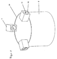
- a tube 2 is provided with three oscillators 1, which are designed as a single-wave exciter cells and each offset by 120 degrees to each other on the tube.
- the imbalance masses 12 receiving waves 11 of the vibrator 1 are respectively directed to the center of the circular cross-section 21 of the tube 2.
- the shafts 11 of the vibrators 1 are rotated in the same direction, whereby the centrifugal forces of the vibrators are added in both the vertical and in the horizontal direction.
- the horizontal centrifugal forces act tangentially to the tube 2, whereby this is set in rotation; the vertical centrifugal forces cause a vertical, sinusoidal oscillation, which, in combination with the weight force of the vibrator acting in the advancing direction, causes a feed movement into the ground.
- the superimposition of the horizontal and vertical movement results in a helical oscillation of the tube in the direction of the ground. In this vibration process, the movement of the tube against a fixed point as an ellipse on the pipe wall is characterized.
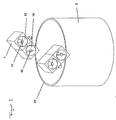
- FIG. 2 In the embodiment according to FIG. 2 are two twin-shaft vibrator 1 at an angle of 35 degrees to the pipe cross-sectional plane 21 employed.
- the vibration generators 1 each have two shafts 11, 13 provided with imbalance masses 12, 14, which are rotated in opposite directions to one another.
- the resulting centrifugal force acts in the direction of the angle of attack of 35 degrees to the tube cross-sectional plane 21.
- this drive form of the tube ground mass, in particular loose sand can be conveyed upwards during the introduction process in the tube via a helix arranged on the tube inner wall. A boring or sucking out of the tube can be omitted in this case.
- FIG. 3 the schematic arrangement for carrying out the method according to the invention is shown.
- a plate 3 is fixed, on the opposite two single-wave vibrator 1 are arranged.
- the waves 11 of the vibration generator 1 are directed in the direction of the center of the plate 3.
- a guide 31 is introduced, through which a guide rod 4 is guided.
- a guide insert 22 is further introduced within the tube 2.
- waves 11 of the vibrator 1 are rotated in the same direction, whereby a helical oscillation of the tube 2 is effected.
- the tube 2 is drilled along the guide rod 4 in the bottom 5.
- the plate 3 with the vibrators 1 and the guide rod 4 is removed from the tube. Subsequently, the material within the tube 2 is discharged and the interior of the tube 2 is filled with concrete. Subsequently, the tube 2 can be pulled out of the ground before the concrete has hardened.
Landscapes
- Engineering & Computer Science (AREA)
- Structural Engineering (AREA)
- Life Sciences & Earth Sciences (AREA)
- General Life Sciences & Earth Sciences (AREA)
- Mining & Mineral Resources (AREA)
- Paleontology (AREA)
- Civil Engineering (AREA)
- General Engineering & Computer Science (AREA)
- Investigation Of Foundation Soil And Reinforcement Of Foundation Soil By Compacting Or Drainage (AREA)
Description
- Die Erfindung betrifft ein Verfahren zum Einbringen von Rohren in den Boden nach dem Oberbegriff des Patentanspruchs 1. Die Erfindung betrifft weiterhin eine Vorrichtung zur Durchführung des vorgenannten Verfahrens nach dem Oberbegriff des Patentanspruchs 11 sowie ein Rohr zum Einbringen in den Boden mittels des vorgenannten Verfahrens nach dem Patentanspruch 15.
- Zur Herstellung von Ortbetonpfählen werden häufig Rohre in den Boden eingebracht, welche anschließend ausgebohrt und nach einem nachfolgenden Betoniervorgang wieder gezogen werden. Sofern es sich bei dem Boden um Sand handelt, kann dieser mit Saugbaggern aus dem eingebrachten Rohr herausgefördert werden.
- Zum Einbringen der Rohre in den Boden kommen üblicherweise Schwingungserzeuger zum Einsatz. Die Schwingungserzeuger sind linear wirkende Schwingungserreger, deren Fliegkraft durch rotierende Umwuchten generiert wird. Die Größe der Unwucht wird auch als statisches Moment bezeichnet. Der Verlauf der Geschwindigkeit des linearen Schwingungserregers entspricht einer periodisch wiederkehrenden Funktion, insbesondere einer Sinusfunktion. Die Wellen auf denen die Unwuchten rotieren sind parallel zueinander angeordnet und bewegen sich gegenläufig, wodurch bewirkt ist, dass sich horizontal auftretende Fliehkräfte gegenseitig aufheben und die effektiv erzeugten Fliehkräfte somit ausschließlich in vertikaler Richtung anliegen.
- Gerammt wird üblicherweise mit freireitenden Vibratoren. Obwohl bekannt ist, dass mäklergeführte Vibratoren aufgrund der vom Rammgerät auf das Rammgut aufgebrachten Vorspannung wesentlich leistungsfähiger sind, werden Rammgeräte für diese Arbeiten bisher kaum eingesetzt, da die mäklergeführten Vibratoren bislang nicht über ausreichend Umwucht verfügen. Inzwischen sind jedoch auch mäklergeführte Vibratoren mit entsprechendem statischen Moment verfügbar. Nachteilig an den vorbekannten Systemen ist, dass der Rammvorgang des Rohres mit dem vorgenannten sinusförmigen Kraftverlauf einen erheblichen Energieeinsatz erfordert und zu Bodenvibrationen führt, die wesentlich durch Reibung des Rammguts im Boden bedingt sind. Ein Verfahren nach dem hervor Oberbegriff des Anspruch 1 geht aus
US 6 672 805 B1 . - Hier will die Erfindung Abhilfe schaffen. Der Erfindung liegt die Aufgabe zugrunde, ein Verfahren zum Einbringen von Rohren in den Boden zu schaffen, bei dem der Energieverbrauch und die Bodenvibration beim Rammvorgang reduziert sind. Gemäß der Erfindung wird diese Aufgabe durch die Merkmale des kennzeichnenden Teils des Patenanspruchs 1 gelöst.
- Mit der Erfindung ist ein Verfahren zum Einbringen von Rohren in den Boden geschaffen, bei dem der Energieverbrauch und die Bodenvibration beim Rammvorgang reduziert sind. Durch die gleichzeitige Rotation des Rohres wird eine Verringerung der Mantelreibung erzielt, da hierdurch die Haftreibung zwischen Rammgut und Boden erheblich reduziert wird. Einem Anhaften des umgebenden Bodens an dem Rohr wird entgegengewirkt. In Folge der ununterbrochenen Gleitreibung zwischen Rammgut und Boden wird gleichzeitig eine Reduzierung der Bodenvibration beim Rammvorgang erzielt. Darüber hinaus wird ein "Einschneiden" des Rohrdurchmessers in den Boden bewirkt, da der untere Rand des Rohrs nicht frontal gegen den Boden gestoßen wird, sondern sich dabei oszillierend bewegt.
- In Weiterbildung der Erfindung wird die schraubenförmige Oszillation des Rohres derart ausgebildet, dass sich eine Bewegung des Rohres als Ellipse auf der Rohrwand abzeichnet, dessen vertikaler Radius zwischen 2 mm und 10 mm, vorzugsweise zwischen 5 mm und 8 mm beträgt. Hierdurch wird der im Stand der Technik hindernde Effekt vermieden, dass das im Rohr befindliche Bodenmaterial am Rohr anhaftet und dadurch die bewegte Masse deutlich vergrößert wird, was eine kleine Amplitude und damit das Erliegen des Vortriebs zur Folge haben kann. Durch die ellipsenförmige Bewegung des Rohrmantels wird die innere Mantelreibung reduziert; die Gefahr des Anhaftens wird verringert.
- In Ausgestaltung der Erfindung wird das Rohr mit wenigstens zwei umlaufend wirkenden Schwingungserzeugern versehen, deren Fliehkraft nicht linear wirkt, sondern umlaufend ist, wobei die die Unwuchten aufnehmenden Wellen der Schwingungserzeuger zum Mittelpunkt des Kreisquerschnitts des Rohres ausgerichtet werden. Im Unterschied zu linear wirkenden Schwingungserzeugern rotieren die auf parallel angeordneten Wellen montierten Unwuchtmassen nicht gegenläufig. Der Kraftverlauf entspricht einem bezüglich der Wellenachse radial wirkenden, mit der Unwuchtmasse rotierenden Vektor. Hierdurch addieren sich nicht nur die vertikalen Fliehkräfte der Unwuchten, sondern zusätzlich auch die horizontalen, tangential zum Rohrmantel gerichteten Fliehkräfte, wodurch eine Rotation des Rohres bewirkt wird.
- Bevorzugt werden die Wellen der Schwingungserzeuger gleichläufig in Rotation versetzt. Hierdurch ist eine Addition der horizontal gerichteten Fliehkräfte bewirkt.
- In weiterer Ausgestaltung der Erfindung werden drei Schwingungserzeuger jeweils um 120 Grad versetzt zueinander an dem Rohr angeordnet. Hierdurch ist eine gleichmäßige, effektive schraubengangförmige Oszillation des Rohres bewirkt. Bevorzugt sind die Schwingungserzeuger einwellig ausgeführt.
- In alternativer Ausgestaltung der Erfindung sind die linear wirkenden Schwingungserzeuger in einem Winkel von 15 und 75 Grad zur Querschnittsebene des Rohres angestellt. Dabei sind die Schwingungserzeuger vorteilhaft derart ausgebildet, dass die effektive Fliehkraft in Richtung des Anstellwinkels der Schwingungserzeuger wirkt. Durch die schräge Anstellung der Schwingungserzeuger an den Rohrrand ist gleichsam eine Schraubengangoszillation des Rohres erzielbar.
- In weiterer Ausgestaltung der Erfindung wird an die Innenwandung des Rohres eine Wendel zur Förderung von Bodenmaterial aus dem Rohr angeordnet. Hierdurch ist eine gleichzeitige Entfernung des von dem Rohr eingeschlossenen Bodenmaterials beim Einbringen des Rohres in den Boden bewirkt.
- Vorteilhaft ist die Wendel treppenförmig, vorzugsweise als Wellblech. ausgebildet. Hierdurch ist eine hohe Reibförderleistung erzielbar, welche auch mit einwelligen Schwingungserzeugern realisierbar ist.
- Der Erfindung liegt weiterhin die Aufgabe zu Grunde, eine Vorrichtung zur Durchführung des vorgenannten Verfahrens zu schaffen, welche eine Reduzierung des Energieverbrauchs beim Rammvorgang ermöglicht. Gemäß der Erfindung wird diese Aufgabe durch die Merkmale des kennzeichnenden Teils des Patentanspruchs 11 gelöst.
- Mit der Erfindung ist eine Vorrichtung zur Durchführung des vorgenannten Verfahrens zum Einbringen von Rohren in den Boden geschaffen, bei dem eine Reduzierung des Energieverbrauchs beim Rammvorgang ermöglicht ist. Die Anordnung der Schwingungserzeuger auf einer Platte ermöglicht eine einfache positionsgenaue Anordnung der Schwingungserzeuger auf dem Rand des in den Boden einzubringenden Rohres. An Stelle einer Platte kann auch ein Rahmen oder ein sonstiges Gestänge vorgesehen sein, an dem die Schwingungserzeuger angeordnet sind.
- Vorteilhaft weist die Platte Mittel zur Aufnahme eines Rohres auf, die derart ausgebildet sind, dass die Aufnahme von Rohren unterschiedlicher Aus- und Innendurchmesser ermöglicht ist. Hierdurch ist der Einsatz der Vorrichtung bei unterschiedlichen Rohrausführungen ermöglicht.
- In Ausgestaltung der Erfindung ist an der Platte eine Vorrichtung zur Befestigung an einem Mäkler angeordnet. Hierdurch ist die Anordnung der Platte an einen Mäkler ermöglicht, wodurch der vertikale Vortrieb des Rohres unterstützt werden kann.
- In Weiterbildung der Erfindung sind drei Schwingungserzeuger jeweils um 120 Grad versetzt zueinander an der Platte angeordnet. Hierdurch ist eine gleichmäßige schraubengangförmige Oszillation des mit der Platte verbundenen Rohres erzielbar.
- In alternativer Ausgestaltung der Erfindung sind wenigstens zwei linear wirkende Schwingungserzeuger in einem Winkel von zwischen 15 und 75 Grad zur Plattenebene angestellt angeordnet. Hierdurch ist gleichsam eine schraubengangförmige Oszillation des mit der Platte verbundenen Rohres erzielbar.
- Gegenstand der Erfindung ist weiterhin ein Rohr zum Einbringen in den Boden über das vorgenannte Verfahren mit den Merkmalen des Patentanspruchs 15. Durch die an der Innenwandung des Rohrs angeordnete Wendel wird das Bodenmaterial während des Einbringprozesses entlang der Wendel aus dem Rohr herausgefördert.
- Andere Weiterbildungen und Ausgestaltungen der Erfindung sind in den übrigen Unteransprüchen angegeben. Ein Ausführungsbeispiel der Erfindung ist in den Zeichnungen dargestellt und wird nachfolgend im Einzelnen beschrieben. Es zeigen:
- Figur 1
- die schematische Darstellung eines Rohres mit drei symmetrisch auf dem Rohrumfang verteilten Schwingungserzeugern, deren Wellen radial zur Rohrmitte angeordnet sind;
- Figur 2
- die schematische Darstellung eines Rohres mit winklig zur Rohrquerschnittsebene angestellten linear wirkende Schwingungs- erzeugern und
- Figur 3
- die schematische Darstellung der Vorrichtung zum Einbringen eines Rohres in den Boden während eines Einbringprozesses.
- Das als Ausführungsbeispiel gewählte Verfahren zum Einbringen eines Rohres 2 in einen Boden 5 wird nachfolgend an Hand der
Figur 1 erläutert: Ein Rohr 2 wird mit drei Schwingungserzeugern 1 versehen, welche als einwellige Erregerzellen ausgebildet sind und jeweils um 120 Grad versetzt zueinander an dem Rohr angeordnet werden. Dabei sind die die Unwuchtmassen 12 aufnehmenden Wellen 11 der Schwingungserzeuger 1 jeweils zum Mittelpunkt des Kreisquerschnitts 21 des Rohres 2 gerichtet. Im Betrieb werden die Wellen 11 der Schwingungserzeuger 1 gleichläufig in Rotation versetzt, wodurch die Fliehkräfte der Schwingungserzeuger sowohl in vertikaler als auch in horizontaler Richtung addiert werden. Die horizontalen Fliehkräfte wirken dabei tangential zum Rohr 2, wodurch dieses in Rotation versetzt wird; die vertikalen Fliehkräfte bewirken eine vertikale, sinusförmige Schwingung, welche addiert mit der in Vorschubrichtung wirkenden Gewichtskraft der Schwingungserzeuger eine Vorschubbewegung in den Boden bewirkt. Die Überlagerung der horizontalen und vertikalen Bewegung ergibt eine schraubengangförmige Oszillation des Rohres in Richtung des Bodens. Bei diesem Vibrationsvorgang zeichnet sich die Bewegung des Rohrs gegenüber einem festen Punkt als Ellipse auf der Rohrwand ab. - Im Ausführungsbeispiel gemäß
Figur 2 sind zwei zweiwellige Schwingungserzeuger 1 in einem Winkel von 35 Grad zur Rohrquerschnittsebene 21 angestellt. Die Schwingungserzeuger 1 weisen jeweils zwei mit Unwuchtmassen 12, 14 versehene Wellen 11, 13 auf, welche gegenläufig zueinander rotiert werden. Die resultierende Fliehkraft wirkt dabei in Richtung des Anstellwinkels von 35 Grad zur Rohrquerschnittsebene 21. Auch hierbei erfolgt durch die horizontalen und vertikalen Fliehkraftkomponenten eine Vorschubbewegung in Richtung des Bodens unter gleichzeitiger Rotation des Rohrs um seine Längsachse. Bei dieser Antriebsform des Rohres kann über eine an der Rohrinnenwand angeordnete Wendel Bodenmasse, insbesondere loser Sand, während des Einbringvorgangs im Rohr aufwärts gefördert werden. Ein Ausbohren bzw. Aussaugen des Rohres kann in diesem Falle entfallen. An dieser Stelle ist anzumerken, dass bei der Antriebsform mittels winklig zur Rohrquerschnittsebene 21 angestellter Schwingungserzeuger in der vorgenannten Art und Weise keine ellipsenförmige Schwingung in der Form erzielbar ist, wie sie im Ausführungsbeispiel gemäßFigur 1 bewirkt ist. Bei ausreichender Reibung, beispielsweise bei Verwendung von Wellblech als Wendel ist der Förderprozess auch mit einwelligen Schwingungserzeugern realisierbar. - In
Figur 3 ist die schematische Anordnung zur Durchführung des erfindungsgemäßen Verfahrens dargestellt. An einem Rohr 2 ist eine Platte 3 befestigt, auf der gegenüberliegend zwei einwellige Schwingungserzeuger 1 angeordnet sind. Die Wellen 11 der Schwingungserzeuger 1 sind dabei in Richtung des Mittelpunkts der Platte 3 gerichtet. Mittig der Platte 3 ist eine Führung 31 eingebracht, durch die ein Führungsstab 4 geführt ist. Zur zentralen Führung des Führungsstabes 4 ist weiterhin innerhalb des Rohres 2 ein Führungseinsatz 22 eingebracht. Im Betrieb werden die mit Unwuchtmassen versehenen Wellen 11 der Schwingungserzeuger 1 gleichläufig in Rotation versetzt, wodurch eine schraubengangförmige Oszillation des Rohres 2 bewirkt ist. Hierdurch wird das Rohr 2 entlang des Führungsstabes 4 in den Boden 5 gebohrt. Nach Einbringen des Rohres 2 wird die Platte 3 mit den Schwingungserzeugern 1 sowie der Führungsstab 4 aus dem Rohr entfernt. Nachfolgend wird das Material innerhalb des Rohres 2 ausgetragen und der Innenraum des Rohrs 2 wird mit Beton verfüllt. Anschließend kann das Rohr 2 vor dem Aushärten des Betons aus dem Boden gezogen werden.
Claims (15)
- Verfahren zum Einbringen eines Rohres in den Boden, wobei das Rohr über wenigstens einen Schwingungserzeuger in Schwingung versetzt wird, dadurch gekennzeichnet, dass die Schwingungen des wenigstens einem Schwingungserzeugers (1) derart auf das Rohr (2) übertragen werden, dass das Rohr (2) zusätzlich zur linearen Bewegung in Rotation versetzt wird, wodurch eine schraubengangförmige Oszillation des Rohres (2) bewirkt wird.
- Verfahren nach Anspruch 1, dadurch gekennzeichnet, dass die schraubengangförmige Oszillation des Rohres (2) derart ausgebildet wird, dass sich eine Bewegung des Rohres (2) als Ellipse auf der Rohrwand abzeichnet, dessen vertikaler Radius zwischen 2 mm und 10 mm, vorzugsweise zwischen 5 mm und 8 mm beträgt.
- Verfahren nach Anspruch 1 oder 2, dadurch gekennzeichnet, dass das Rohr mit wenigstens zwei Schwingungserzeugern versehen wird, wobei die die Unwuchten (12, 14) aufnehmenden Wellen (11, 13) der Schwingungserzeuger (1) zum Mittelpunkt des Kreisquerschnitts (21) des Rohres (2) ausgerichtet werden.
- Verfahren nach Anspruch 3, dadurch gekennzeichnet, dass die Wellen (11, 13) der umlaufend wirkenden Schwingungserzeuger (1) gleichläufig zueinander in Rotation versetzt werden.
- Verfahren nach Anspruch 4, dadurch gekennzeichnet, dass der Schwingungserzeuger derart ausgebildet ist, dass eine umlaufend wirkende Fliehkraft erzeugt wird.
- Verfahren nach Anspruch 3 bis 5, dadurch gekennzeichnet, dass die Schwingungserzeuger (1) einwellig ausgeführt sind.
- Verfahren nach einem der Ansprüche 3 bis 6, dadurch gekennzeichnet, dass mindestens drei Schwingungserzeuger (1), symmetrisch auf dem Rohrumfang verteilt an dem Rohr (2) angeordnet werden.
- Verfahren nach Anspruch 3, dadurch gekennzeichnet, dass mindestens zwei linear wirkende Schwingungserzeuger (1) in einem Winkel von zwischen 15 und 75 Grad zur Rohrquerschnittsebene angestellt sind.
- Verfahren nach einem der vorgenannten Ansprüche, dadurch gekennzeichnet, dass an die Innenwandung des Rohrs (2) eine Wendel zur Förderung von Bodenmaterial aus dem Rohr (2) angeordnet wird.
- Verfahren nach Anspruch 9, dadurch gekennzeichnet, dass die Wendel treppenförmig, vorzugsweise als Wellblech, ausgebildet ist.
- Vorrichtung zur Durchführung eines Verfahrens nach einem der vorgenannten Ansprüche, umfassend eine Platte (3), auf der wenigstens zwei Schwingungserzeuger (1) angeordnet sind, deren die Unwuchten (12, 14) aufnehmende Wellen (11, 13) zum Mittelpunkt der Platte gerichtet sind, welche auf einem Rohr befestigbar ist.
- Vorrichtung nach Anspruch 11, dadurch gekennzeichnet, dass die Platte (3) Mittel zur Aufnahme eines Rohrs (2) aufweist, die derart ausgebildet sind, das die Aufnahme von Rohren unterschiedlicher Außen- und Innendurchmesser ermöglicht ist.
- Vorrichtung nach Anspruch 11 oder 12, dadurch gekennzeichnet, dass drei Schwingungserzeuger (1) jeweils um 120 Grad versetzt zueinander an dem Rohr (2) angeordnet sind.
- Vorrichtung nach Anspruch 11 oder 12, dadurch gekennzeichnet, dass wenigstens zwei Schwingungserzeuger (1) in einem Winkel von zwischen 15 und 75 Grad, vorzugsweise zwischen 30 und 60 Grad zur Rohrquerschnittsebene angestellt angeordnet sind.
- Vorrichtung nach einem der Ansprüche 11 bis 14, dadurch gekennzeichnet, dass diese ein Rohr zum Einbringen in den Boden mittels einem Verfahren nach Anspruch 1 enthält, an dessen innenwandung eine Wendel zur Förderung von Bodenmaterial aus dem Rohr (2) während des Einbringprozesses angeordnet ist.
Priority Applications (2)
| Application Number | Priority Date | Filing Date | Title |
|---|---|---|---|
| EP09006634A EP2251490B1 (de) | 2009-05-16 | 2009-05-16 | Vorrichtung und Verfahren zum Einbringen von Rohren in den Boden |
| AT09006634T ATE550494T1 (de) | 2009-05-16 | 2009-05-16 | Vorrichtung und verfahren zum einbringen von rohren in den boden |
Applications Claiming Priority (1)
| Application Number | Priority Date | Filing Date | Title |
|---|---|---|---|
| EP09006634A EP2251490B1 (de) | 2009-05-16 | 2009-05-16 | Vorrichtung und Verfahren zum Einbringen von Rohren in den Boden |
Publications (2)
| Publication Number | Publication Date |
|---|---|
| EP2251490A1 EP2251490A1 (de) | 2010-11-17 |
| EP2251490B1 true EP2251490B1 (de) | 2012-03-21 |
Family
ID=40848745
Family Applications (1)
| Application Number | Title | Priority Date | Filing Date |
|---|---|---|---|
| EP09006634A Not-in-force EP2251490B1 (de) | 2009-05-16 | 2009-05-16 | Vorrichtung und Verfahren zum Einbringen von Rohren in den Boden |
Country Status (2)
| Country | Link |
|---|---|
| EP (1) | EP2251490B1 (de) |
| AT (1) | ATE550494T1 (de) |
Family Cites Families (4)
| Publication number | Priority date | Publication date | Assignee | Title |
|---|---|---|---|---|
| DE3576376D1 (de) * | 1985-12-13 | 1990-04-12 | Plasser Bahnbaumasch Franz | Einrichtung zum eintreiben von fundamentrohren od. dgl. in erdschichten mittels vibrationsvorrichtung. |
| DE10029984A1 (de) * | 2000-06-26 | 2002-02-21 | Fritz Gehbauer | Verfahren zur Regelung des Betriebs einer Vibrationsramme |
| US6672805B1 (en) * | 2001-09-27 | 2004-01-06 | American Piledriving Equipment, Inc. | Systems and methods for driving large diameter caissons |
| DE102007049435A1 (de) * | 2007-10-16 | 2009-04-30 | Thyssenkrupp Gft Tiefbautechnik Gmbh | Vorrichtung zur Erzeugung von Schwingungen |
-
2009
- 2009-05-16 EP EP09006634A patent/EP2251490B1/de not_active Not-in-force
- 2009-05-16 AT AT09006634T patent/ATE550494T1/de active
Also Published As
| Publication number | Publication date |
|---|---|
| EP2251490A1 (de) | 2010-11-17 |
| ATE550494T1 (de) | 2012-04-15 |
Similar Documents
| Publication | Publication Date | Title |
|---|---|---|
| EP2105214B1 (de) | Schwingungserzeuger | |
| DE102006045518A1 (de) | Ultraschall-Schwingungswandler zum Ultraschallbohren | |
| EP3951057A1 (de) | Bodenbearbeitungswalzensystem für eine bodenbearbeitungsmaschine | |
| EP3450631B1 (de) | Tiefenrüttler mit verstellbarer unwucht | |
| DE1634267A1 (de) | Verfahren und Vorrichtung zum Eintreiben langgestreckter Koerper in koerniges Medium in deren Laengsrichtung | |
| EP2105213A1 (de) | Schwingungserzeuger | |
| EP3243573B1 (de) | Schwingungserzeuger | |
| EP2251490B1 (de) | Vorrichtung und Verfahren zum Einbringen von Rohren in den Boden | |
| EP3215678B1 (de) | Vibrationsramme | |
| EP2392413B1 (de) | Vibrationsramme | |
| DE102014019139A1 (de) | Tiefenrüttler mit veränderbarer Unwucht | |
| EP2732100A1 (de) | Unwuchterreger für ein bodenverdichtungsgerät | |
| DE934220C (de) | Verfahren und Vorrichtung zum Eintreiben oder Ziehen von Pfaehlen, Bohlen, Rohren u. dgl. | |
| EP2242590B1 (de) | Unwuchterreger mit einer oder mehreren rotierbaren unwuchten | |
| EP3165290B1 (de) | Schwingungserzeuger und verfahren zum einbringen eines rammgutes in einen boden | |
| EP3230531B1 (de) | Verfahren und vorrichtungen zur baugrundverbesserung | |
| EP0589196B1 (de) | Vorrichtung zur Herstellung eines Betonrohres | |
| DE2802648C2 (de) | In der Marschrichtung umsteuerbare Rüttelplatte | |
| EP3384096B1 (de) | Anordnung zur bereitstellung einer pulsierenden druckkraft | |
| DE858532C (de) | Verfahren zum Loesen fest gewordener Rohre in Tiefbohrungen durch Schwingungen | |
| DE102004035128A1 (de) | Prüfvorrichtung und Verfahren zum Prüfen von Fahrzeug-Stabilisatoren | |
| DE4413471C1 (de) | Verfahren zur Herstellung von liegenden und/oder geneigten, verfestigten Säulen im Baugrund sowie Vorrichtung zur Durchführung des Verfahrens nebst Anwendung | |
| DE102011008576A1 (de) | Verfahren und Vorrichtung zur Erzeugung einer schwingenden Bewegung einer Masse | |
| DE3129722A1 (de) | Verfahren zum grabenlosen verlegen von rohrleitungen | |
| EP3357589A1 (de) | Schwingungserzeuger und verfahren zum erzeugen von schwingungen |
Legal Events
| Date | Code | Title | Description |
|---|---|---|---|
| PUAI | Public reference made under article 153(3) epc to a published international application that has entered the european phase |
Free format text: ORIGINAL CODE: 0009012 |
|
| 17P | Request for examination filed |
Effective date: 20091021 |
|
| AK | Designated contracting states |
Kind code of ref document: A1 Designated state(s): AT BE BG CH CY CZ DE DK EE ES FI FR GB GR HR HU IE IS IT LI LT LU LV MC MK MT NL NO PL PT RO SE SI SK TR |
|
| AX | Request for extension of the european patent |
Extension state: AL BA RS |
|
| GRAP | Despatch of communication of intention to grant a patent |
Free format text: ORIGINAL CODE: EPIDOSNIGR1 |
|
| GRAS | Grant fee paid |
Free format text: ORIGINAL CODE: EPIDOSNIGR3 |
|
| GRAA | (expected) grant |
Free format text: ORIGINAL CODE: 0009210 |
|
| AK | Designated contracting states |
Kind code of ref document: B1 Designated state(s): AT BE BG CH CY CZ DE DK EE ES FI FR GB GR HR HU IE IS IT LI LT LU LV MC MK MT NL NO PL PT RO SE SI SK TR |
|
| REG | Reference to a national code |
Ref country code: GB Ref legal event code: FG4D Free format text: NOT ENGLISH |
|
| REG | Reference to a national code |
Ref country code: CH Ref legal event code: EP |
|
| REG | Reference to a national code |
Ref country code: IE Ref legal event code: FG4D Free format text: LANGUAGE OF EP DOCUMENT: GERMAN |
|
| REG | Reference to a national code |
Ref country code: AT Ref legal event code: REF Ref document number: 550494 Country of ref document: AT Kind code of ref document: T Effective date: 20120415 |
|
| REG | Reference to a national code |
Ref country code: DE Ref legal event code: R096 Ref document number: 502009003052 Country of ref document: DE Effective date: 20120516 |
|
| REG | Reference to a national code |
Ref country code: NL Ref legal event code: T3 |
|
| PG25 | Lapsed in a contracting state [announced via postgrant information from national office to epo] |
Ref country code: LT Free format text: LAPSE BECAUSE OF FAILURE TO SUBMIT A TRANSLATION OF THE DESCRIPTION OR TO PAY THE FEE WITHIN THE PRESCRIBED TIME-LIMIT Effective date: 20120321 Ref country code: HR Free format text: LAPSE BECAUSE OF FAILURE TO SUBMIT A TRANSLATION OF THE DESCRIPTION OR TO PAY THE FEE WITHIN THE PRESCRIBED TIME-LIMIT Effective date: 20120321 Ref country code: NO Free format text: LAPSE BECAUSE OF FAILURE TO SUBMIT A TRANSLATION OF THE DESCRIPTION OR TO PAY THE FEE WITHIN THE PRESCRIBED TIME-LIMIT Effective date: 20120621 |
|
| LTIE | Lt: invalidation of european patent or patent extension |
Effective date: 20120321 |
|
| PG25 | Lapsed in a contracting state [announced via postgrant information from national office to epo] |
Ref country code: LV Free format text: LAPSE BECAUSE OF FAILURE TO SUBMIT A TRANSLATION OF THE DESCRIPTION OR TO PAY THE FEE WITHIN THE PRESCRIBED TIME-LIMIT Effective date: 20120321 Ref country code: GR Free format text: LAPSE BECAUSE OF FAILURE TO SUBMIT A TRANSLATION OF THE DESCRIPTION OR TO PAY THE FEE WITHIN THE PRESCRIBED TIME-LIMIT Effective date: 20120622 Ref country code: FI Free format text: LAPSE BECAUSE OF FAILURE TO SUBMIT A TRANSLATION OF THE DESCRIPTION OR TO PAY THE FEE WITHIN THE PRESCRIBED TIME-LIMIT Effective date: 20120321 |
|
| PG25 | Lapsed in a contracting state [announced via postgrant information from national office to epo] |
Ref country code: CY Free format text: LAPSE BECAUSE OF FAILURE TO SUBMIT A TRANSLATION OF THE DESCRIPTION OR TO PAY THE FEE WITHIN THE PRESCRIBED TIME-LIMIT Effective date: 20120321 |
|
| PG25 | Lapsed in a contracting state [announced via postgrant information from national office to epo] |
Ref country code: EE Free format text: LAPSE BECAUSE OF FAILURE TO SUBMIT A TRANSLATION OF THE DESCRIPTION OR TO PAY THE FEE WITHIN THE PRESCRIBED TIME-LIMIT Effective date: 20120321 Ref country code: SE Free format text: LAPSE BECAUSE OF FAILURE TO SUBMIT A TRANSLATION OF THE DESCRIPTION OR TO PAY THE FEE WITHIN THE PRESCRIBED TIME-LIMIT Effective date: 20120321 Ref country code: PL Free format text: LAPSE BECAUSE OF FAILURE TO SUBMIT A TRANSLATION OF THE DESCRIPTION OR TO PAY THE FEE WITHIN THE PRESCRIBED TIME-LIMIT Effective date: 20120321 Ref country code: CZ Free format text: LAPSE BECAUSE OF FAILURE TO SUBMIT A TRANSLATION OF THE DESCRIPTION OR TO PAY THE FEE WITHIN THE PRESCRIBED TIME-LIMIT Effective date: 20120321 Ref country code: RO Free format text: LAPSE BECAUSE OF FAILURE TO SUBMIT A TRANSLATION OF THE DESCRIPTION OR TO PAY THE FEE WITHIN THE PRESCRIBED TIME-LIMIT Effective date: 20120321 Ref country code: IS Free format text: LAPSE BECAUSE OF FAILURE TO SUBMIT A TRANSLATION OF THE DESCRIPTION OR TO PAY THE FEE WITHIN THE PRESCRIBED TIME-LIMIT Effective date: 20120721 Ref country code: SI Free format text: LAPSE BECAUSE OF FAILURE TO SUBMIT A TRANSLATION OF THE DESCRIPTION OR TO PAY THE FEE WITHIN THE PRESCRIBED TIME-LIMIT Effective date: 20120321 |
|
| BERE | Be: lapsed |
Owner name: ABI ANLAGENTECHNIK-BAUMASCHINEN-INDUSTRIEBEDARF M Effective date: 20120531 |
|
| PG25 | Lapsed in a contracting state [announced via postgrant information from national office to epo] |
Ref country code: PT Free format text: LAPSE BECAUSE OF FAILURE TO SUBMIT A TRANSLATION OF THE DESCRIPTION OR TO PAY THE FEE WITHIN THE PRESCRIBED TIME-LIMIT Effective date: 20120723 Ref country code: SK Free format text: LAPSE BECAUSE OF FAILURE TO SUBMIT A TRANSLATION OF THE DESCRIPTION OR TO PAY THE FEE WITHIN THE PRESCRIBED TIME-LIMIT Effective date: 20120321 |
|
| PG25 | Lapsed in a contracting state [announced via postgrant information from national office to epo] |
Ref country code: MC Free format text: LAPSE BECAUSE OF NON-PAYMENT OF DUE FEES Effective date: 20120531 |
|
| PLBE | No opposition filed within time limit |
Free format text: ORIGINAL CODE: 0009261 |
|
| STAA | Information on the status of an ep patent application or granted ep patent |
Free format text: STATUS: NO OPPOSITION FILED WITHIN TIME LIMIT |
|
| PG25 | Lapsed in a contracting state [announced via postgrant information from national office to epo] |
Ref country code: DK Free format text: LAPSE BECAUSE OF FAILURE TO SUBMIT A TRANSLATION OF THE DESCRIPTION OR TO PAY THE FEE WITHIN THE PRESCRIBED TIME-LIMIT Effective date: 20120321 |
|
| 26N | No opposition filed |
Effective date: 20130102 |
|
| REG | Reference to a national code |
Ref country code: IE Ref legal event code: MM4A |
|
| PG25 | Lapsed in a contracting state [announced via postgrant information from national office to epo] |
Ref country code: MK Free format text: LAPSE BECAUSE OF FAILURE TO SUBMIT A TRANSLATION OF THE DESCRIPTION OR TO PAY THE FEE WITHIN THE PRESCRIBED TIME-LIMIT Effective date: 20120321 Ref country code: IT Free format text: LAPSE BECAUSE OF FAILURE TO SUBMIT A TRANSLATION OF THE DESCRIPTION OR TO PAY THE FEE WITHIN THE PRESCRIBED TIME-LIMIT Effective date: 20120321 Ref country code: BE Free format text: LAPSE BECAUSE OF NON-PAYMENT OF DUE FEES Effective date: 20120531 |
|
| REG | Reference to a national code |
Ref country code: DE Ref legal event code: R097 Ref document number: 502009003052 Country of ref document: DE Effective date: 20130102 |
|
| PG25 | Lapsed in a contracting state [announced via postgrant information from national office to epo] |
Ref country code: IE Free format text: LAPSE BECAUSE OF NON-PAYMENT OF DUE FEES Effective date: 20120516 Ref country code: ES Free format text: LAPSE BECAUSE OF FAILURE TO SUBMIT A TRANSLATION OF THE DESCRIPTION OR TO PAY THE FEE WITHIN THE PRESCRIBED TIME-LIMIT Effective date: 20120702 |
|
| PG25 | Lapsed in a contracting state [announced via postgrant information from national office to epo] |
Ref country code: BG Free format text: LAPSE BECAUSE OF FAILURE TO SUBMIT A TRANSLATION OF THE DESCRIPTION OR TO PAY THE FEE WITHIN THE PRESCRIBED TIME-LIMIT Effective date: 20120621 Ref country code: MT Free format text: LAPSE BECAUSE OF FAILURE TO SUBMIT A TRANSLATION OF THE DESCRIPTION OR TO PAY THE FEE WITHIN THE PRESCRIBED TIME-LIMIT Effective date: 20120321 |
|
| REG | Reference to a national code |
Ref country code: CH Ref legal event code: PL |
|
| GBPC | Gb: european patent ceased through non-payment of renewal fee |
Effective date: 20130516 |
|
| PG25 | Lapsed in a contracting state [announced via postgrant information from national office to epo] |
Ref country code: LI Free format text: LAPSE BECAUSE OF NON-PAYMENT OF DUE FEES Effective date: 20130531 Ref country code: CH Free format text: LAPSE BECAUSE OF NON-PAYMENT OF DUE FEES Effective date: 20130531 |
|
| PG25 | Lapsed in a contracting state [announced via postgrant information from national office to epo] |
Ref country code: TR Free format text: LAPSE BECAUSE OF FAILURE TO SUBMIT A TRANSLATION OF THE DESCRIPTION OR TO PAY THE FEE WITHIN THE PRESCRIBED TIME-LIMIT Effective date: 20120321 Ref country code: GB Free format text: LAPSE BECAUSE OF NON-PAYMENT OF DUE FEES Effective date: 20130516 |
|
| PG25 | Lapsed in a contracting state [announced via postgrant information from national office to epo] |
Ref country code: LU Free format text: LAPSE BECAUSE OF NON-PAYMENT OF DUE FEES Effective date: 20120516 |
|
| PG25 | Lapsed in a contracting state [announced via postgrant information from national office to epo] |
Ref country code: HU Free format text: LAPSE BECAUSE OF FAILURE TO SUBMIT A TRANSLATION OF THE DESCRIPTION OR TO PAY THE FEE WITHIN THE PRESCRIBED TIME-LIMIT Effective date: 20090516 |
|
| PGFP | Annual fee paid to national office [announced via postgrant information from national office to epo] |
Ref country code: FR Payment date: 20140516 Year of fee payment: 6 Ref country code: DE Payment date: 20140508 Year of fee payment: 6 Ref country code: NL Payment date: 20140520 Year of fee payment: 6 |
|
| REG | Reference to a national code |
Ref country code: AT Ref legal event code: MM01 Ref document number: 550494 Country of ref document: AT Kind code of ref document: T Effective date: 20140516 |
|
| PG25 | Lapsed in a contracting state [announced via postgrant information from national office to epo] |
Ref country code: AT Free format text: LAPSE BECAUSE OF NON-PAYMENT OF DUE FEES Effective date: 20140516 |
|
| REG | Reference to a national code |
Ref country code: DE Ref legal event code: R119 Ref document number: 502009003052 Country of ref document: DE |
|
| REG | Reference to a national code |
Ref country code: NL Ref legal event code: MM Effective date: 20150601 |
|
| REG | Reference to a national code |
Ref country code: FR Ref legal event code: ST Effective date: 20160129 |
|
| PG25 | Lapsed in a contracting state [announced via postgrant information from national office to epo] |
Ref country code: DE Free format text: LAPSE BECAUSE OF NON-PAYMENT OF DUE FEES Effective date: 20151201 Ref country code: NL Free format text: LAPSE BECAUSE OF NON-PAYMENT OF DUE FEES Effective date: 20150601 |
|
| PG25 | Lapsed in a contracting state [announced via postgrant information from national office to epo] |
Ref country code: FR Free format text: LAPSE BECAUSE OF NON-PAYMENT OF DUE FEES Effective date: 20150601 |