EP2251481A1 - Waschmaschine - Google Patents
Waschmaschine Download PDFInfo
- Publication number
- EP2251481A1 EP2251481A1 EP09159847A EP09159847A EP2251481A1 EP 2251481 A1 EP2251481 A1 EP 2251481A1 EP 09159847 A EP09159847 A EP 09159847A EP 09159847 A EP09159847 A EP 09159847A EP 2251481 A1 EP2251481 A1 EP 2251481A1
- Authority
- EP
- European Patent Office
- Prior art keywords
- drawer
- laundry washing
- pump
- seat
- container
- Prior art date
- Legal status (The legal status is an assumption and is not a legal conclusion. Google has not performed a legal analysis and makes no representation as to the accuracy of the status listed.)
- Granted
Links
- 238000010412 laundry washing Methods 0.000 title claims abstract description 59
- 238000011282 treatment Methods 0.000 claims abstract description 88
- XLYOFNOQVPJJNP-UHFFFAOYSA-N water Substances O XLYOFNOQVPJJNP-UHFFFAOYSA-N 0.000 claims description 38
- 239000012530 fluid Substances 0.000 claims description 25
- 230000005540 biological transmission Effects 0.000 claims description 10
- 230000033001 locomotion Effects 0.000 claims description 9
- 238000010276 construction Methods 0.000 claims description 5
- 230000009471 action Effects 0.000 claims description 4
- 238000006073 displacement reaction Methods 0.000 claims description 3
- 239000013505 freshwater Substances 0.000 claims description 3
- 238000005406 washing Methods 0.000 description 34
- 239000007788 liquid Substances 0.000 description 10
- 239000003599 detergent Substances 0.000 description 8
- 238000004891 communication Methods 0.000 description 7
- 239000002979 fabric softener Substances 0.000 description 4
- 238000001746 injection moulding Methods 0.000 description 4
- 230000008901 benefit Effects 0.000 description 3
- 230000005484 gravity Effects 0.000 description 3
- 239000000203 mixture Substances 0.000 description 3
- 230000009467 reduction Effects 0.000 description 3
- 238000004140 cleaning Methods 0.000 description 2
- 230000008878 coupling Effects 0.000 description 2
- 238000010168 coupling process Methods 0.000 description 2
- 238000005859 coupling reaction Methods 0.000 description 2
- 239000000843 powder Substances 0.000 description 2
- 230000003213 activating effect Effects 0.000 description 1
- 230000009286 beneficial effect Effects 0.000 description 1
- 230000007423 decrease Effects 0.000 description 1
- 238000007599 discharging Methods 0.000 description 1
- 238000000605 extraction Methods 0.000 description 1
- 238000010438 heat treatment Methods 0.000 description 1
- 238000003780 insertion Methods 0.000 description 1
- 230000037431 insertion Effects 0.000 description 1
- 210000002445 nipple Anatomy 0.000 description 1
- 230000003287 optical effect Effects 0.000 description 1
- 230000000149 penetrating effect Effects 0.000 description 1
- 239000008237 rinsing water Substances 0.000 description 1
- 230000000630 rising effect Effects 0.000 description 1
- 238000000926 separation method Methods 0.000 description 1
- 230000032258 transport Effects 0.000 description 1
- 230000000007 visual effect Effects 0.000 description 1
Images


Classifications
-
- D—TEXTILES; PAPER
- D06—TREATMENT OF TEXTILES OR THE LIKE; LAUNDERING; FLEXIBLE MATERIALS NOT OTHERWISE PROVIDED FOR
- D06F—LAUNDERING, DRYING, IRONING, PRESSING OR FOLDING TEXTILE ARTICLES
- D06F39/00—Details of washing machines not specific to a single type of machines covered by groups D06F9/00 - D06F27/00
- D06F39/02—Devices for adding soap or other washing agents
- D06F39/022—Devices for adding soap or other washing agents in a liquid state
-
- D—TEXTILES; PAPER
- D06—TREATMENT OF TEXTILES OR THE LIKE; LAUNDERING; FLEXIBLE MATERIALS NOT OTHERWISE PROVIDED FOR
- D06F—LAUNDERING, DRYING, IRONING, PRESSING OR FOLDING TEXTILE ARTICLES
- D06F39/00—Details of washing machines not specific to a single type of machines covered by groups D06F9/00 - D06F27/00
- D06F39/02—Devices for adding soap or other washing agents
Definitions
- the present invention relates in general to laundry washing appliances, such as laundry washers or combined laundry washers and dryers.
- laundry washing appliances such as laundry washers or combined laundry washers and dryers.
- the term "laundry” is here intended to include clothes and garments.
- the present invention relates to a laundry washing appliance having an auto-dosing dispensing arrangement for the laundry washing treatment liquids (e.g ., detergents, softeners and the like).
- Laundry washing appliances like laundry washers and combined washers and dryers make use of laundry washing treatment products in the laundry washing cycle; such treatment products include for example detergents and softeners.
- the laundry washing appliances generally include receptacles for the laundry treatment products, for example in the form of drawers provided in the appliance cabinet, from where, during the laundry washing cycle, the treatment products are taken and dispensed into the washing tub.
- Auto-dosing dispensing of laundry treatment products to be used during a washing cycle is believed to be advantageous under several respects. For example, it would translate into a reduction of time and efforts of the users, which would be levied from the burden of dosing the correct amount of laundry treatment products, and would beneficially reflect on the environment pollution, because wastes would be reduced or eliminated.
- EP 1690972 discloses a softener-dosing container for electrical household appliances, having an upper casing positioned above the mixing compartment or drawer wherein the cleaning products are introduced.
- the dispensing reservoir comprises a watertight, hermetically sealed tray of large capacity, partially or totally removable with respect to a cavity defined in the upper casing and it has a drain hole for the passage of fabric softener to the drawer with the intermediation of a gear pump, in addition to incorporating a portion adjacent to the tray which forms part of the casing which includes electrical components to operate a motor which, through a transmission and by means of magnetized plates, determines the rotation of the pump positioned in the removable tray to push the fabric softener to the drawer.
- the body of the pump has an outlet gasket equipped with a discharge opening to push the fabric softener to the mixing compartment or drawer; a non-return valve is provided in correspondence with the discharge opening consisting of a sphere pressed by a spring which covers the discharge opening or leaves free passage for the discharge of the fabric softener once the spring pressure is exceeded.
- the Applicant has tackled the problem of finding an effective solution to the problem of providing an arrangement for auto-dosing of laundry treatment products in laundry washing appliances.
- a laundry washing appliance comprising a cabinet accommodating a laundry washing tub and a dispensing arrangement for dispensing laundry washing treatment products to be used during laundry washing.
- the dispensing arrangement comprises a drawer slidable within a seat provided in the cabinet, the drawer defining at least one container for laundry washing treatment products.
- At least one suction pump is provided, associated with the at least one container and fluidly connected to the laundry washing tub for delivering thereto dosed amounts of the treatment products.
- a fluid connection between the at least one suction pump and the at least one container is provided.
- the at least one suction pump and the fluid connection are arranged so as to enable the suction of the dosed amounts of treatment product from above a surface of the treatment product contained in the container.
- the at least one suction pump may be arranged so that in operation it results above a surface level of the treatment product contained in the at least one container.
- the at least one suction pump may comprise a pump motor part and a pump body part separable from one another; in an embodiment of the invention, the pump motor part is mounted to the drawer seat, and the pump body part is mounted to the drawer.
- the pump motor part may be mounted at a rear of the drawer seat, and the pump body part may be mounted at a rear of the drawer.
- the dispensing arrangement may comprise a mixing chamber, the at least one suction pump associated with the at least one container being fluidly connected to the mixing chamber for delivering thereto dosed amounts of the treatment products, the mixing chamber being fluidly connected to a water inlet and to the laundry washing tub.
- the laundry washing appliance may comprise a water feed channel connected to an outlet of at least one electrovalve which in use is connectable to an external water main, the water feed channel being fluidly connected to the mixing chamber.
- the at least one suction pump associated with the at least one container may be fluidly connected to the water load chamber for delivering thereto dosed amounts of the treatment products sucked from the at least one container.
- the water load chamber may comprise a first sub-chamber, whereinto fresh water is loadable, and a second sub-chamber, where the dosed amounts of treatment products delivered by the at least one pump are discharged, the first and second sub-chambers being partially separated from one another.
- the mixing chamber may be interposed between the pump motor part and the pump body part.
- the mixing chamber and/or the water load channel are preferably in single-piece construction with the drawer seat.
- the at least one suction pump may be a positive displacement pump.
- the pump motor part comprises an electric motor and a drive axle.
- the pump body part may comprise a motion transmission axle configured to releasably engage the drive axle; a piston driven by the motion transmission axle and movable within a pump chamber; a first non-return valve at an intake of the suction pump, and a second non-return valve at a delivery outlet of the suction pump.
- the first and second non-return valves may be caused to open and close in phase opposition by pressure deltas caused by the movement of the piston within said pump chamber.
- the laundry washing appliance may comprise at least one valve for fluidly connecting the at least one container to the at least one suction pump, said valve being realized so as to automatically close and cut off the fluid connection between the at least one container and the at least one suction pump when the drawer is even partially extracted from the seat, and to automatically open and establish the fluid connection between the at least one container and the at least one suction pump when the drawer is pushed into the seat.
- the at least one valve may comprise at least a valve portion that is attached to the drawer seat, said valve portion being arranged at the top of the drawer seat, so that the drawer is slidable within the seat below the at least one valve.
- Said at least one valve may comprise:
- FIG. 1 there is shown a laundry washing appliance 100 according to an embodiment of the present invention.
- the laundry washing appliance 100 is, in the considered example, a laundry washer, nevertheless the solutions that will be described hereinafter can be applied as well and straightforwardly to other types of laundry washer appliances, for example to combined laundry washers and driers.
- the laundry washer 100 comprises an external cabinet 105, within which a washing tub accommodating a rotating washing drum is housed (neither the washing tub, nor the drum are visible in the drawing, being per - se conventional and not relevant for the understanding of the invention embodiments to be described).
- a front wall 110 of the cabinet 105 is provided with an aperture with which there is associated a door 115, for enabling the user to access the washing drum so as to load/unload the items to be washed.
- a machine control panel 120 is provided, with operational input and setting devices (like for example pushbuttons, rotary selectors and the like) through which the user can set the desired washing preferences, and display devices.
- the laundry washer 100 is equipped with a dispensing arrangement for dispensing laundry washing treatments products, e.g . detergents and softeners, to the washing tub.
- the dispensing arrangement comprises, located aside the control panel 120, a drawer 125, slidably accommodated in a drawer seat (denoted 227 in the following figures and described in detail later on) provided in the cabinet 105 and extending essentially from the front to the rear of the machine; the drawer, as will be described in the following, is intended to be exploited by the user for loading laundry washing treatments products to be used during laundry washing cycles.
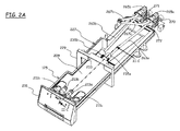
- Figures 2A - 2L A first solution is shown in Figures 2A - 2L .
- Figure 2A shows in perspective view the drawer 125 in a partially pulled-out, open condition (partially extracted from its seat);
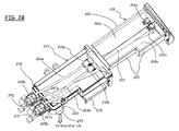
- Figure 2B shows, in perspective from a different angle, the drawer 125 fully extracted from the seat;
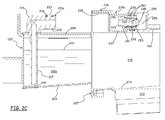
- Figure 2C is a partial cross-sectional view taken along plane II-C-II-C of Figure 2A ;
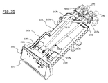
- Figure 2D shows the drawer 125 in a closed condition (wherein the drawer 125 is fully pushed into its seat);
- Figure 2E is a partial cross-sectional view taken along plane II-E-II-E of Figure 2D ;
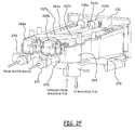
- Figure 2F is a perspective view from the rear of the drawer and seat assembly;
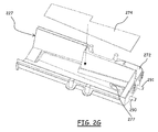
- Figure 2G is a perspective and exploded view of a bottom part of the drawer seat;
- Figure 2H is a top view of the rear part of the drawer seat;
- Figure 2L is a cross-sectional view of the drawer seat taken along
- the drawer 125 is shaped so as to define two containers 201a and 201b (visible in Figure 2B ) for two different laundry washing treatments products in liquid form; for example, the container 201a, of higher capacity, is for the washing detergent, and the container 201b is for the softener.
- the two containers 201a and 201b are defined by the drawer bottom wall 203 and by the drawer lateral, perimetral walls 205, and are separated by an intermediate wall 207 rising from the bottom wall 203 of the drawer 125 and extending the whole length thereof.
- the drawer bottom wall 203 is inclined towards the drawer front, so that the height of the two containers 201a and 201b decreases going from the drawer front towards the rear thereof.
- the two containers 201a and 201b are open at the top, and a (preferably) removable cap 209 is provided for closing the two containers (by removing the cap 209, the user may gain access to the containers for, e.g ., cleaning purposes).
- load apertures 211a and 211b are provided, one over each of the containers 201a and 201b, for pouring the proper treatment product into the containers.
- the suction pipes 213a and 213b Associated to the cap 209 are two suction pipes 213a and 213b, one in correspondence of the detergent container 201a and the other in correspondence of the softener container 201b.
- the suction pipes 213a and 213b comprise each a vertical pipe portion 217 penetrating into the respective container substantially down to the bottom thereof (so that, when the container 201a or 201b is filled with the proper treatment product, an aperture 219 at the bottom of the vertical pipe portion 217 is located well below the level of the treatment product surface 220), and an elbow portion 221 positioned over the cap 209; on a free end portion 223 of the elbow portion 221, a pair of O-rings 225 are fit in respective annular notches.
- the drawer seat is shaped so as to slidably accommodate the drawer 125 and guide the drawer in the extraction/insertion movements.
- the drawer seat 227 comprises a front frame 229 for the abutment of a drawer front panel 231; the front frame 229 has a recess 233 formed in a top side thereof, the recess 233 being adapted to allow the passage of the elbow portions 221 of the two suction pipes 213a and 213b when the drawer 125 is fully pushed into the cabinet 105 (a condition in which the drawer front panel 231 results essentially flush with the control panel 120).
- Each of the two valves comprises a hollow valve body 235a, 235b protrudring from the front frame 229 towards the rear of the cabinet 105; the two valve bodies 235a and 235b, which in the shown exemplary embodiment are formed in one piece with the front frame 229, are positioned so as to result aligned to the elbow portions 221 of the two suction pipes 213a and 213b, and have a first portion 237 of shape and size adapted to tightly receive therein the free end portion 223 of the elbow portions 221 of the suction pipes 213a and 213b, the O-rings 225 provided on the free end portion 223 ensuring a tight seal when the free end portions 223 of the elbow portions 221 are inserted into the first portion 237 of the valve bodies 235a and 235b.
- the valve bodies 235a and 235b have a second portion 239 following the first portion 237 and accommodating a slidable valve member 241 forming a fluid passage cut-off element.
- the slidable valve member 241 is a hollow, generically cylindrical member, open at a first base 243 thereof facing the elbow portions 221, and closed at an opposite, second base 245, with one or more apertures 247 formed in the perimetral wall thereof in correspondence of the second base 245, the aperture(s) 247 putting the hollow interior of the valve member 241 into fluid communication with the exterior.
- a bias helical spring 249 is fit outside the valve member, between an annular ridge 251 projecting from the valve member 241 perimetral wall and a shoulder 253 formed at the end of the second portion 239 of the valve bodies 235a and 235b.
- a pipe coupling 255 is fit onto the second portion 239 of the valve bodies 235a and 235b, with a couple of O-rings 257 fit on each of the valve body second portions 239 for ensuring the seal; the pipe coupling 255 extends farther towards the rear of the cabinet 105 with respect to the second portion 239 of the valve bodies 235a and 235b, to define a liquid chamber 259, and terminates with a nipple 261 adapted to the connection of a flexible pipe 263a, 263b leading to the intake of a respective suction pump 265a, 265b.
- the two pumps 265a and 265b are positive displacement pumps, for example volumetric pumps, reciprocating pumps, gear pumps, and are adapted to displace dosed amounts of liquids.
- the two pumps 265a and 265b have each a delivery outlet which is fluidly connected, by means of a respective flexible pipe 267a and 267b, to respective inlets of a mixing chamber 269, located at a rear corner (in particular, but not limitatively, the rear left corner as seen from the front) of the seat 227 for the drawer 125; preferably the mixing chamber 269 is in a single-piece construction with the drawer seat 227, and is obtained by a plastic injection-moulding process.
- Outlets of two electrovalves 270 and 271 are fluidly connected, through respective conduits 290 and 291, to a water load chamber 272, located behind the drawer seat 227 and for example in one piece therewith.
- the water load chamber 272 is shaped so as to define a channel that turns around the rear left corner of the drawer seat 227 and opens into the mixing chamber 269.
- the two electrovalves 270 and 271 are respectively connectable, by means of hoses, to a cold water and a hot water delivery ports intended to be present in the premises of the user where the appliance is to be located (in alternative embodiments of the invention, only one electrovalve may be present, for the connection to the cold water or hot water delivery port).
- the conduits 290 and 291 are formed in a single-piece construction with the water load chamber 272, and are obtained by a plastic injection-moulding process.
- the two electrovalves are for example attached to the rear of the water load chamber by means of brackets.
- the water load chamber 272 forms an air gap (air break) between the outlets of the electrovalves and the mixing chamber 269.
- the mixing chamber 269 opens at the bottom into a manifold 277 which is in fluid communication with the washing tub (for example, to this purpose a flexible hose, a bellow - not shown in the drawings - may be used), for delivering thereto the washing water, possibly mixed with the laundry treatment products, and the rinsing water.
- a manifold 277 which is in fluid communication with the washing tub (for example, to this purpose a flexible hose, a bellow - not shown in the drawings - may be used), for delivering thereto the washing water, possibly mixed with the laundry treatment products, and the rinsing water.
- Level sensors for sensing the level of laundry treatment products may be provided within, or be operatively associated with the two containers 201a and 201b.
- the level sensors which may for example be one or more capacitive sensors, optical sensors, conductivity sensors, and may be mounted on the drawers, or on the drawer seat, for example along the side walls thereof, are used to provide the user with indications (for example, through visual indicators provided on the control panel 120) about the necessity of refilling the containers 201a and 201b.
- An air space 273 is formed at the bottom of the drawer seat 227; the air space 273 is for example defined by the bottom walls of the drawer seat 227 and a (possibly removable, or formed in one piece with the drawer seat) panel 274 that separates the air space 273 at the bottom of the drawer seat 227 from the upper area 275 of the drawer seat 227 intended to accommodate the drawer 125.
- the air space 273 is in air communication with the washing tub, for example through the flexible hose or bellow that connects the manifold 277 to the washing tub).
- the air space 273 has a discharge aperture 276, that opens within the machine cabinet 105.
- the user may extract the drawer 125 from its seat 227 and pour the desired laundry treatment products, e.g . detergent and/or softener (depending on the washing cycle he/she wishes the machine to perform) into the proper containers 201a and/or 201b formed in the drawer 125.
- the desired laundry treatment products e.g . detergent and/or softener (depending on the washing cycle he/she wishes the machine to perform) into the proper containers 201a and/or 201b formed in the drawer 125.
- the desired laundry treatment products e.g . detergent and/or softener (depending on the washing cycle he/she wishes the machine to perform) into the proper containers 201a and/or 201b formed in the drawer 125.
- the two elbow portions 221 penetrates into the first portions 237 of the valve bodies 235a and 235b, and the rims of the free ends of the elbow portions 221, abutting the rim of the valve members 241, push the latter against the bias action of the bias springs 249.
- the valve members 241 thus slide rearward until the apertures 247 formed in the perimetral walls thereof open into the liquid chambers 259, and in this way a fluid path is established between the containers 201a and 201b and the pumps 265a and 265b.
- the pump 265a or the pump 265b When either the pump 265a or the pump 265b is activated (according to the timing of the washing program), it sucks a dosed amount of the respective treatment product, detergent and/or softener, from the container 201a or 201b formed in the drawer 125; the treatment product is then delivered to the mixing chamber 269, where it may be mixed with cold or hot water taken in from the water mains, and the mix thus obtained is then delivered to the washing tub.
- the two containers 201a and 201b provide a bulk storage of laundry treatment products within the appliance; the capacity of the containers 201a and 201b may be higher than the amount of laundry treatment product necessary for one washing cycle, and may suffice for several washing cycles, so that the user no longer needs to pour into the appliance the laundry treatment products before starting every washing cycle.
- An auto-dosing of the treatment products is achieved thanks to the provision of the pumps 265a and 265b, which take from the containers 201a and 201b the precise amount of treatment product needed for the single washing cycle; this translates into a saving of laundry treatment products, with a beneficial impact also on the environment.
- the proper doses of treatment products are taken from the containers 201a and 201b in the drawer 125 by the suction action of the pumps 265a and 265b, i.e . the treatment products do not fall by gravity from the containers.
- the suction is from above the level of the surface of the treatment products stored in the containers, i.e . the dose of treatment product to be delivered to the washing tub is raised above the surface level. This allows avoiding any possible leakage of treatment products.
- the water load chamber 272 provides a separation between the outlets of the electrovalves 270 and 271 and the mixing chamber 269 where the pipes 267a and 267b from the pumps 265a and 265b open. In this way, it is ensured that no laundry treatment product leaks into the electrovalves and returns to the cold/hot water mains.
- the drawer results in fluid communication with the washing tub only through the pumps, thus vapours that originate in the tub during the laundry washing cannot be discharged through the drawer.
- the air space 273 in air communication with the washing tub defines a vapours discharge path that allows discharging vapours coming from the washing tub during the washing cycles; the vapours are discharged into the machine cabinet.
- the discharge of the vapours also prevents that the laundry treatment products stored in the containers 201a and 201b of the drawer 125 are heated up by the vapours, which is believed to be undesirable, since repeatedly heating up the laundry treatment products might alter their properties.
- An advantage of this solution resides in that when the drawer 125 is pulled out of the seat 227 for, e.g ., the replenishment of the treatment products containers 201a and 201b, any possible leakage of treatment products from the valve bodies 235a and 235b ( i.e ., residues of treatment product in the valve bodies) drops onto the cap 209, from where it can be easily removed by the user.
- the drawer seat 227, the mixing chamber 269, the water load chamber 272, the manifold 277 may be formed as a single-piece component, obtained by a plastic injection-moulding process; this reduction of separated parts simplifies assembling operations.
- Figures 3A - 3L show another solution according to an embodiment of the present invention.
- Figure 3A shows in perspective view the drawer for pouring laundry treatment products partially extracted from its seat
- Figure 3B shows in perspective the drawer fully inserted into its seat
- Figure 3C shows in perspective the detail of a dosing pump for delivering dosed amounts of laundry washing treatment products to a washing tub
- Figure 3D shows the dosing pump, in a perspective similar to Figure 3C and in partial cross-section, in a first operating condition
- Figure 3E is a front view of the perspective view of Figure 3D
- Figure 3F shows the dosing pump, in a perspective and in partial cross-section similarly to Figure 3C , in a second operating condition
- Figure 3G is a front view of the perspective view of Figure 3F
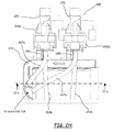
- Figure 3I shows in perspective and partially in cross-section the dosing pump, in the second operating condition
- Figure 3H is a perspective view of the drawer seat
- Figure 3L shows in perspective a cross-section of the drawer seat taken along a horizontal plane.
- this solution differs from that described in the foregoing for the fact that the two suction pipes 213a and 213b, the two valves formed in the drawer seat 227, and the two suction pumps 265a and 265b are replaced by two pumps 365a and 365b having the structure described in the following.
- Each of the two pumps 365a, 365b comprises a pump motor part 301a, 301b, and a pump body part 303a, 303b.
- the pump motor part 301a, 301b, and the pump body part 303a, 303b of each of the two pumps 365a and 365b are separable from one another.
- the pump motor parts 301a and 301b each comprising a casing 305 accommodating an electric motor, particularly a step-by-step motor, are mounted to the drawer seat 227, at the rear thereof.
- a driving axle 307 protrudes from the casing 305 of each pump motor part 301a, 301b, towards the front of the drawer seat 227.
- a face gear 309 is mounted at the free end of the driving axle 307.
- the pump body parts 303a and 303b are mounted to the drawer 125, at the rear thereof, onto the cap 209, and are each one in alignment with the respective pump motor part 301a, 301b.
- Each of the pump body parts 303a and 303b comprises a motion transmission axle 311 terminating at one end thereof with a face gear 313 adapted to releasably mesh with the face gear 309 of the corresponding pump motor part 301a, 301b.
- the big end 315 of a connecting rod 317 is pivotally connected to the opposite end of the transmission axle 311, in eccentric position (with respect to a rotation axis of the transmission axle 311).
- the small end of the connecting rod 317 is hinged to a pin 319 of a piston 321 slidable vertically within a cylinder 323.
- the bottom part 325 of the cylinder 323 interior is fluidly connected, through a channel 327, to a first non-return valve 329 arranged at an opposite end of the channel 327 and interposed between the channel 327 and a suction pipe 331 extending downwards into a respective one of the two containers 201a and 201b.
- a vertical channel 333 branches off from the channel 327 in intermediate position along the length of the latter.
- a second non-return valve 335 is placed along the vertical channel 333; the second non-return valve 335 is interposed between the channel 333 and a delivery channel 337, opening into the water load chamber 272 at the top thereof.
- Each of the first and second non-return valves 329 and 335 comprises a respective fluid passage cut-off movable member 339, 341; the generic movable member 339, 341 is movable between a first position, in which it closes a valve passage and thus cuts off the fluid passage, and a second position in which it opens the valve passage and thus does not prevent the fluid passage.
- the movable members 339 and 341 are caused to move by pressure deltas induced in the channels 333 and 337 as a consequence of the movement of the piston 321 within the cylinder 323.
- the pump electric motor is activated to cause the rise of the piston 321 towards the top dead center (a condition depicted in Figures 3D and 3E )
- the depression induced within the channels 327 and 333 causes the movable member 339 of the first non-return valve 329 to move to the position in which the valve passage is open, while the movable member 341 of the second non-return valve 335 is caused to move to the position in which it closes the valve passage; the same depression causes the washing treatment product to be sucked from the container 201a, 201b into the channel 327 through the suction pipe 331.
- the transmission axle 331 and the delivery duct 338 are covered by a removable box-shaped cap 338.
- a vertical baffle 343 is provided within the water load chamber 272, to separate a first sub-chamber 345, whereinto the fresh water is loaded, from a second sub-chamber 347, where the treatment products delivered through the delivery channels 337 are discharged.
- the baffle 343 extends slightly less than the water load chamber 272, so that the two sub-chambers 345 and 347 are in fluid communication at their ends.
- the water load chamber 272, the vertical baffle 343, the mixing chamber 269 and the manifold 277 are realized in single-piece construction with the drawer seat 227, by means of a plastic injection-moulding process.
- level sensors for sensing the level of laundry treatment products may be provided within, or be operatively associated with the two containers 201a and 201b.
- the user may extract the drawer 125 from its seat 227 and pour the desired laundry treatment products, e.g . detergent and/or softener (depending on the washing cycle he/she wishes to be performed by the machine) into the proper containers 201a and/or 201b formed in the drawer 125.
- the desired laundry treatment products e.g . detergent and/or softener (depending on the washing cycle he/she wishes to be performed by the machine) into the proper containers 201a and/or 201b formed in the drawer 125.
- the desired laundry treatment products e.g . detergent and/or softener (depending on the washing cycle he/she wishes to be performed by the machine) into the proper containers 201a and/or 201b formed in the drawer 125.
- the face gear 313 of the transmission axle 311 disengages from the face gear 309 on the driving axle 307.
- the user pushes the drawer 125 into its seat 227; the face gear 313 engages the face gear 309 (this engagement
- either one of the pump electric motors is activated.
- the pump sucks from the associated container 201a, 201b in the drawer 125 a dosed amount of laundry washing treatment product, which is discharged into the sub-chamber 347.
- Fresh (cold or hot) water is loaded into the sub-chamber 345 by activating either one of the electrovalves 270 and 271.
- a flash of water passes into the sub-chamber 347 and transports the laundry treatment products to the mixing chamber 269; here, the laundry treatment product mixes with water, and the mix is delivered to the washing tub.
- An advantage of this second embodiment is that it requires less parts, in particular less pipes.
- a dosed amount of treatment product to be delivered to the washing tub is sucked out from the respective container from above the level of the surface of the treatment product stored in the container, i . e . there is no fall by gravity, and this prevents undesired leakages of products.
Landscapes
- Engineering & Computer Science (AREA)
- Textile Engineering (AREA)
- Detail Structures Of Washing Machines And Dryers (AREA)
- Accessory Of Washing/Drying Machine, Commercial Washing/Drying Machine, Other Washing/Drying Machine (AREA)
- Containers And Packaging Bodies Having A Special Means To Remove Contents (AREA)
Priority Applications (9)
| Application Number | Priority Date | Filing Date | Title |
|---|---|---|---|
| PL18199776.8T PL3460120T3 (pl) | 2009-05-11 | 2009-05-11 | Urządzenie piorące do prania |
| EP09159847.4A EP2251481B1 (de) | 2009-05-11 | 2009-05-11 | Waschmaschine |
| EP18199776.8A EP3460120B1 (de) | 2009-05-11 | 2009-05-11 | Waschmaschine |
| PL09159847T PL2251481T3 (pl) | 2009-05-11 | 2009-05-11 | Urządzenie do prania materiałów pranych |
| RU2011150208/12A RU2544128C2 (ru) | 2009-05-11 | 2010-04-29 | Устройство для стирки белья |
| PCT/EP2010/055835 WO2010130586A1 (en) | 2009-05-11 | 2010-04-29 | Laundry washing appliance |
| US13/319,909 US9057150B2 (en) | 2009-05-11 | 2010-04-29 | Laundry washing appliance with dosing dispenser |
| BRPI1014270-3A BRPI1014270B1 (pt) | 2009-05-11 | 2010-04-29 | Máquina de lavar roupas |
| CN201080020606.1A CN102421958B (zh) | 2009-05-11 | 2010-04-29 | 洗衣设备 |
Applications Claiming Priority (1)
| Application Number | Priority Date | Filing Date | Title |
|---|---|---|---|
| EP09159847.4A EP2251481B1 (de) | 2009-05-11 | 2009-05-11 | Waschmaschine |
Related Child Applications (2)
| Application Number | Title | Priority Date | Filing Date |
|---|---|---|---|
| EP18199776.8A Division EP3460120B1 (de) | 2009-05-11 | 2009-05-11 | Waschmaschine |
| EP18199776.8A Previously-Filed-Application EP3460120B1 (de) | 2009-05-11 | 2009-05-11 | Waschmaschine |
Publications (2)
| Publication Number | Publication Date |
|---|---|
| EP2251481A1 true EP2251481A1 (de) | 2010-11-17 |
| EP2251481B1 EP2251481B1 (de) | 2018-11-07 |
Family
ID=41090301
Family Applications (2)
| Application Number | Title | Priority Date | Filing Date |
|---|---|---|---|
| EP09159847.4A Active EP2251481B1 (de) | 2009-05-11 | 2009-05-11 | Waschmaschine |
| EP18199776.8A Active EP3460120B1 (de) | 2009-05-11 | 2009-05-11 | Waschmaschine |
Family Applications After (1)
| Application Number | Title | Priority Date | Filing Date |
|---|---|---|---|
| EP18199776.8A Active EP3460120B1 (de) | 2009-05-11 | 2009-05-11 | Waschmaschine |
Country Status (7)
| Country | Link |
|---|---|
| US (1) | US9057150B2 (de) |
| EP (2) | EP2251481B1 (de) |
| CN (1) | CN102421958B (de) |
| BR (1) | BRPI1014270B1 (de) |
| PL (2) | PL3460120T3 (de) |
| RU (1) | RU2544128C2 (de) |
| WO (1) | WO2010130586A1 (de) |
Cited By (16)
| Publication number | Priority date | Publication date | Assignee | Title |
|---|---|---|---|---|
| CN103215788A (zh) * | 2012-03-22 | 2013-07-24 | 无锡小天鹅股份有限公司 | 洗衣机及其洗涤剂投放泵组件 |
| EP2465996A3 (de) * | 2010-12-07 | 2013-12-04 | BSH Bosch und Siemens Hausgeräte GmbH | Wasserführendes Haushaltsgerät mit einer Behandlungsmittelschale |
| EP2735634A1 (de) * | 2012-11-26 | 2014-05-28 | Samsung Electronics Co., Ltd | Waschmaschine |
| EP2733249A3 (de) * | 2014-02-20 | 2014-08-06 | V-Zug AG | Waschmaschine mit Vorratsbehältern für Waschmittel |
| ITTO20130693A1 (it) * | 2013-08-14 | 2015-02-15 | Elbi Int Spa | Struttura di cassetto per l'erogazione dosata di almeno un agente di lavaggio in una macchina lavatrice, in particolare una macchina lavabiancheria. |
| WO2015043860A1 (en) * | 2013-09-27 | 2015-04-02 | Arcelik Anonim Sirketi | A washer comprising an automatic dosing unit |
| WO2015074688A1 (en) * | 2013-11-20 | 2015-05-28 | Electrolux Appliances Aktiebolag | Laundry washing machine with detergent drawer comprising a control panel |
| EP3192916A1 (de) * | 2016-01-14 | 2017-07-19 | Vestel Beyaz Esya Sanayi Ve Ticaret A.S. | Waschmaschinenschublade |
| EP3348700A1 (de) | 2017-01-12 | 2018-07-18 | Electrolux Appliances Aktiebolag | Gerät mit einem wassereinlassmodul |
| EP3617381A1 (de) * | 2018-08-30 | 2020-03-04 | Electrolux Appliances Aktiebolag | Waschvorrichtung mit einem einschub mit verbesserter oberabdeckung |
| EP3617379A1 (de) * | 2018-08-30 | 2020-03-04 | Electrolux Appliances Aktiebolag | Wäschebehandlungsgerät mit einer verbesserten schublade |
| CN112301674A (zh) * | 2019-07-30 | 2021-02-02 | 东芝生活电器株式会社 | 衣物处理装置 |
| US11136706B2 (en) | 2016-03-24 | 2021-10-05 | Electrolux Appliances Aktiebolag | Laundry washing machine comprising a water softening device and a local electronic control unit |
| EP3722484B1 (de) * | 2019-04-12 | 2022-03-16 | LG Electronics Inc. | Waschmaschine und steuerungsverfahren dafür |
| EP3786341B1 (de) | 2019-08-29 | 2022-11-09 | LG Electronics Inc. | Waschmittelvorratsbehälter und verfahren zur herstellung desselben |
| WO2023184809A1 (zh) * | 2022-03-31 | 2023-10-05 | 无锡小天鹅电器有限公司 | 分配器盒、洗涤剂投放装置、洗涤设备、洗涤设备套件 |
Families Citing this family (33)
| Publication number | Priority date | Publication date | Assignee | Title |
|---|---|---|---|---|
| US10815604B2 (en) | 2013-07-03 | 2020-10-27 | Samsung Electronics Co., Ltd. | Automatic detergent supply apparatus and washing machine having the same |
| KR101343712B1 (ko) * | 2013-07-16 | 2013-12-20 | 김학열 | 드럼세탁기의 세제공급통 |
| CN104372579A (zh) * | 2013-08-16 | 2015-02-25 | 代傲电子控制(南京)有限公司 | 一种辅助添加装置 |
| EP2878727B1 (de) * | 2013-11-28 | 2017-08-23 | LG Electronics Inc. | Waschmaschine |
| WO2015133798A1 (en) * | 2014-03-04 | 2015-09-11 | Lg Electronics Inc. | Washing machine |
| DE102014105841A1 (de) * | 2014-04-25 | 2015-10-29 | Miele & Cie. Kg | Wäschebehandlungsmaschine mit einer Vorrichtung für die Zugabe von flüssigen Wasch- und/oder Pflegemitteln |
| KR102487097B1 (ko) | 2014-05-30 | 2023-01-11 | 엘지전자 주식회사 | 의류처리장치 |
| US9644308B2 (en) * | 2014-08-12 | 2017-05-09 | Haier Us Appliance Solutions, Inc. | Nozzle formed in a dispensing apparatus |
| CN104762792B (zh) * | 2015-03-25 | 2018-06-22 | 无锡小天鹅股份有限公司 | 洗衣机进水组件以及洗衣机 |
| US10655264B2 (en) * | 2015-08-04 | 2020-05-19 | Whirlpool Corporation | Laundry treating appliance with internal housing |
| KR102407647B1 (ko) * | 2015-08-17 | 2022-06-10 | 엘지전자 주식회사 | 건조기 |
| KR102471915B1 (ko) | 2016-01-05 | 2022-11-29 | 엘지전자 주식회사 | 세탁제펌프 및 이를 구비한 세탁물처리장치 |
| KR102493966B1 (ko) * | 2016-02-16 | 2023-02-01 | 주식회사 위니아전자 | 세탁기 |
| KR20170096315A (ko) * | 2016-02-16 | 2017-08-24 | 동부대우전자 주식회사 | 세탁기 및 그 세탁기에 구비된 액체첨가제 투입장치 |
| CN106637835B (zh) | 2017-02-20 | 2019-08-23 | 无锡小天鹅电器有限公司 | 用于洗衣机的投放装置和具有其的洗衣机 |
| CN108729139B (zh) * | 2017-04-17 | 2020-12-29 | 青岛海尔洗涤电器有限公司 | 一种洗涤添加剂盒 |
| US11441255B2 (en) | 2017-04-17 | 2022-09-13 | Chongqing Haier Drum Washing Machine | Detergent additive box and mounting structure thereof, and distribution box |
| CN108729138B (zh) * | 2017-04-17 | 2021-04-09 | 青岛海尔洗涤电器有限公司 | 一种洗涤添加剂盒 |
| CN108729140B (zh) * | 2017-04-17 | 2020-12-22 | 青岛海尔滚筒洗衣机有限公司 | 一种洗涤添加剂盒 |
| CN108930142B (zh) * | 2017-05-27 | 2021-03-16 | 青岛海尔洗涤电器有限公司 | 一种洗涤添加剂盒及洗衣机 |
| DE102017215258A1 (de) * | 2017-08-31 | 2019-02-28 | BSH Hausgeräte GmbH | Wäschepflegegerät mit einem Dosiermodul |
| DE102017222499A1 (de) | 2017-12-12 | 2019-06-13 | BSH Hausgeräte GmbH | Wäschepflegegerät mit einem Flüssigkeitszuführelement |
| CN108193442B (zh) * | 2018-02-07 | 2021-01-15 | 南京中竞科电子科技有限公司 | 一种洗涤剂投放装置及洗衣机 |
| PL3617374T3 (pl) * | 2018-08-30 | 2022-02-14 | Electrolux Appliances Aktiebolag | Urządzenie pralnicze z łatwą w obsłudze szufladką |
| KR102555839B1 (ko) | 2018-11-15 | 2023-07-13 | 엘지전자 주식회사 | 세탁기 |
| KR102604689B1 (ko) * | 2019-04-12 | 2023-11-20 | 엘지전자 주식회사 | 세탁기 |
| KR102644821B1 (ko) * | 2019-04-12 | 2024-03-06 | 엘지전자 주식회사 | 세탁기 |
| KR20210027019A (ko) * | 2019-08-29 | 2021-03-10 | 엘지전자 주식회사 | 세제공급장치와 이를 포함하는 의류처리장치 |
| EP3786340B1 (de) | 2019-08-29 | 2024-06-05 | LG Electronics Inc. | Schublade |
| KR20210027021A (ko) * | 2019-08-29 | 2021-03-10 | 엘지전자 주식회사 | 드로워 및 이를 포함하는 의류 처리 장치 |
| EP3786336B1 (de) | 2019-08-29 | 2024-05-22 | LG Electronics Inc. | Waschmittelzuführvorrichtung |
| KR20210094285A (ko) * | 2020-01-21 | 2021-07-29 | 엘지전자 주식회사 | 의류처리장치 |
| USD1024468S1 (en) * | 2022-01-17 | 2024-04-23 | Shenghui Wang | Laundry detergent holder |
Citations (4)
| Publication number | Priority date | Publication date | Assignee | Title |
|---|---|---|---|---|
| EP0528768A1 (de) * | 1991-06-12 | 1993-02-24 | CANDY S.p.A. | Vorrichtung zum Spenden von Waschmittel und Waschmittelzusätzen in Waschmaschinen |
| EP1690972A1 (de) | 2003-12-05 | 2006-08-16 | Plásticos Mondragón, S.L.U. | Weichspülmitteldosierungsbehälter für elektrische haushaltsgeräte |
| EP1884584A2 (de) * | 2006-07-31 | 2008-02-06 | Indesit Company S.p.A. | Waschmaschine, insbesondere Wäschewaschmaschine, mit einem Waschmittelspender mit großer Kapazität |
| EP2011913A1 (de) * | 2007-07-03 | 2009-01-07 | Electrolux Home Products Corporation N.V. | Waschmaschine |
Family Cites Families (5)
| Publication number | Priority date | Publication date | Assignee | Title |
|---|---|---|---|---|
| DE3246127A1 (de) | 1982-12-13 | 1984-06-14 | Bosch-Siemens Hausgeräte GmbH, 7000 Stuttgart | Geraet mit einrichtungen fuer die bevorratung, dosierung und zugabe von fluessigen wasch- und spuelmitteln |
| EP1444394B1 (de) | 2001-09-11 | 2007-07-25 | Arçel K A. | Dosiervorrichtung für flüssigwaschmittel |
| DE102006029953A1 (de) | 2006-06-29 | 2008-01-03 | BSH Bosch und Siemens Hausgeräte GmbH | Waschmaschine mit einem steuerbaren Frischwasserzulauf und Verfahren zum Betreiben einer solchen Waschmaschine |
| WO2008010671A2 (en) | 2006-07-18 | 2008-01-24 | Lg Electronics Inc. | Laundry dryer |
| DE102007050920B3 (de) * | 2007-10-23 | 2008-12-04 | Miele & Cie. Kg | Dosiervorrichtung für flüssige oder zähflüssige Behandlungsmittel einer Waschmaschine und Waschmaschine |
-
2009
- 2009-05-11 EP EP09159847.4A patent/EP2251481B1/de active Active
- 2009-05-11 PL PL18199776.8T patent/PL3460120T3/pl unknown
- 2009-05-11 PL PL09159847T patent/PL2251481T3/pl unknown
- 2009-05-11 EP EP18199776.8A patent/EP3460120B1/de active Active
-
2010
- 2010-04-29 BR BRPI1014270-3A patent/BRPI1014270B1/pt active IP Right Grant
- 2010-04-29 US US13/319,909 patent/US9057150B2/en active Active
- 2010-04-29 RU RU2011150208/12A patent/RU2544128C2/ru active
- 2010-04-29 WO PCT/EP2010/055835 patent/WO2010130586A1/en active Application Filing
- 2010-04-29 CN CN201080020606.1A patent/CN102421958B/zh not_active Expired - Fee Related
Patent Citations (4)
| Publication number | Priority date | Publication date | Assignee | Title |
|---|---|---|---|---|
| EP0528768A1 (de) * | 1991-06-12 | 1993-02-24 | CANDY S.p.A. | Vorrichtung zum Spenden von Waschmittel und Waschmittelzusätzen in Waschmaschinen |
| EP1690972A1 (de) | 2003-12-05 | 2006-08-16 | Plásticos Mondragón, S.L.U. | Weichspülmitteldosierungsbehälter für elektrische haushaltsgeräte |
| EP1884584A2 (de) * | 2006-07-31 | 2008-02-06 | Indesit Company S.p.A. | Waschmaschine, insbesondere Wäschewaschmaschine, mit einem Waschmittelspender mit großer Kapazität |
| EP2011913A1 (de) * | 2007-07-03 | 2009-01-07 | Electrolux Home Products Corporation N.V. | Waschmaschine |
Cited By (32)
| Publication number | Priority date | Publication date | Assignee | Title |
|---|---|---|---|---|
| EP2465996A3 (de) * | 2010-12-07 | 2013-12-04 | BSH Bosch und Siemens Hausgeräte GmbH | Wasserführendes Haushaltsgerät mit einer Behandlungsmittelschale |
| WO2013139311A1 (zh) * | 2012-03-22 | 2013-09-26 | 无锡小天鹅股份有限公司 | 洗衣机及其洗涤剂投放泵组件 |
| CN103215788A (zh) * | 2012-03-22 | 2013-07-24 | 无锡小天鹅股份有限公司 | 洗衣机及其洗涤剂投放泵组件 |
| CN103215788B (zh) * | 2012-03-22 | 2016-01-13 | 无锡小天鹅股份有限公司 | 洗衣机及其洗涤剂投放泵组件 |
| US9493900B2 (en) | 2012-03-22 | 2016-11-15 | Wuxi Little Swan Co., Ltd. | Washing machine and detergent delivery pump assembly thereof |
| CN103215788B8 (zh) * | 2012-03-22 | 2016-09-07 | 无锡小天鹅股份有限公司 | 洗衣机及其洗涤剂投放泵组件 |
| EP3091115A1 (de) * | 2012-11-26 | 2016-11-09 | Samsung Electronics Co., Ltd. | Waschmaschine |
| EP2735634A1 (de) * | 2012-11-26 | 2014-05-28 | Samsung Electronics Co., Ltd | Waschmaschine |
| US10077527B2 (en) | 2012-11-26 | 2018-09-18 | Samsung Electronics Co., Ltd. | Liquid sensing apparatus, detergent supply apparatus, and washing machine having the same |
| ITTO20130693A1 (it) * | 2013-08-14 | 2015-02-15 | Elbi Int Spa | Struttura di cassetto per l'erogazione dosata di almeno un agente di lavaggio in una macchina lavatrice, in particolare una macchina lavabiancheria. |
| WO2015022622A1 (en) * | 2013-08-14 | 2015-02-19 | Elbi International S.P.A. | Drawer structure for dispensing metered amounts of at least one washing agent in a washing machine, in particular a laundry washing machine |
| US9644307B2 (en) | 2013-08-14 | 2017-05-09 | Elbi International Spa | Drawer structure for dispensing metered amounts of washing agent in a washing machine |
| CN105722444A (zh) * | 2013-09-27 | 2016-06-29 | 阿塞里克股份有限公司 | 一种包括自动定量给料单元的洗涤器 |
| WO2015043860A1 (en) * | 2013-09-27 | 2015-04-02 | Arcelik Anonim Sirketi | A washer comprising an automatic dosing unit |
| CN105722444B (zh) * | 2013-09-27 | 2018-11-06 | 阿塞里克股份有限公司 | 一种包括自动定量给料单元的洗涤器 |
| US10378140B2 (en) | 2013-11-20 | 2019-08-13 | Electrolux Appliances Aktiebolag | Laundry washing machine with detergent drawer comprising a control panel |
| WO2015074688A1 (en) * | 2013-11-20 | 2015-05-28 | Electrolux Appliances Aktiebolag | Laundry washing machine with detergent drawer comprising a control panel |
| EP2733249A3 (de) * | 2014-02-20 | 2014-08-06 | V-Zug AG | Waschmaschine mit Vorratsbehältern für Waschmittel |
| EP3192916A1 (de) * | 2016-01-14 | 2017-07-19 | Vestel Beyaz Esya Sanayi Ve Ticaret A.S. | Waschmaschinenschublade |
| US11136706B2 (en) | 2016-03-24 | 2021-10-05 | Electrolux Appliances Aktiebolag | Laundry washing machine comprising a water softening device and a local electronic control unit |
| EP3348700A1 (de) | 2017-01-12 | 2018-07-18 | Electrolux Appliances Aktiebolag | Gerät mit einem wassereinlassmodul |
| WO2018130404A1 (en) | 2017-01-12 | 2018-07-19 | Electrolux Appliances Aktiebolag | Appliance comprising a water inlet module |
| US11220778B2 (en) | 2017-01-12 | 2022-01-11 | Electrolux Appliances Aktiebolag | Appliance comprising a water inlet module |
| EP3617381A1 (de) * | 2018-08-30 | 2020-03-04 | Electrolux Appliances Aktiebolag | Waschvorrichtung mit einem einschub mit verbesserter oberabdeckung |
| EP3617379A1 (de) * | 2018-08-30 | 2020-03-04 | Electrolux Appliances Aktiebolag | Wäschebehandlungsgerät mit einer verbesserten schublade |
| WO2020043621A1 (en) * | 2018-08-30 | 2020-03-05 | Electrolux Appliances Aktiebolag | Laundry appliance having a drawer provided with improved top cover |
| WO2020043630A1 (en) * | 2018-08-30 | 2020-03-05 | Electrolux Appliances Aktiebolag | Laundry treatment appliance comprising an improved drawer |
| US11535973B2 (en) | 2018-08-30 | 2022-12-27 | Electrolux Appliances Aktiebolag | Laundry treatment appliance comprising an improved drawer |
| EP3722484B1 (de) * | 2019-04-12 | 2022-03-16 | LG Electronics Inc. | Waschmaschine und steuerungsverfahren dafür |
| CN112301674A (zh) * | 2019-07-30 | 2021-02-02 | 东芝生活电器株式会社 | 衣物处理装置 |
| EP3786341B1 (de) | 2019-08-29 | 2022-11-09 | LG Electronics Inc. | Waschmittelvorratsbehälter und verfahren zur herstellung desselben |
| WO2023184809A1 (zh) * | 2022-03-31 | 2023-10-05 | 无锡小天鹅电器有限公司 | 分配器盒、洗涤剂投放装置、洗涤设备、洗涤设备套件 |
Also Published As
| Publication number | Publication date |
|---|---|
| WO2010130586A1 (en) | 2010-11-18 |
| PL3460120T3 (pl) | 2024-01-29 |
| EP2251481B1 (de) | 2018-11-07 |
| CN102421958A (zh) | 2012-04-18 |
| PL2251481T3 (pl) | 2019-08-30 |
| EP3460120B1 (de) | 2023-07-12 |
| US20120096901A1 (en) | 2012-04-26 |
| US9057150B2 (en) | 2015-06-16 |
| BRPI1014270B1 (pt) | 2020-09-29 |
| RU2544128C2 (ru) | 2015-03-10 |
| CN102421958B (zh) | 2014-10-29 |
| EP3460120A1 (de) | 2019-03-27 |
| BRPI1014270A2 (pt) | 2016-04-05 |
| RU2011150208A (ru) | 2013-06-20 |
Similar Documents
| Publication | Publication Date | Title |
|---|---|---|
| EP2251481B1 (de) | Waschmaschine | |
| US9506183B2 (en) | Laundry washing appliance with dosing dispenser | |
| EP3467182B1 (de) | Wäschebehandlungsanwendung mit massenausgabevorrichtung | |
| US4009598A (en) | Automatic treating agent dispenser for washing appliance | |
| EP3502336B1 (de) | Waschmaschine | |
| US20070261177A1 (en) | Bulk dispensing system for washing machine | |
| EP3502335B1 (de) | Waschmaschine | |
| EA018881B1 (ru) | Водопроводящий бытовой прибор с системой автоматического дозирования и способ автоматического дозирования | |
| US20170306552A1 (en) | Washing Machine Appliance with on Demand Fluids | |
| US11105033B2 (en) | Integrated single dose and bulk dispenser for a laundry treating appliance | |
| US10760199B2 (en) | Household appliance with a bulk dispenser | |
| JP7507346B2 (ja) | 洗濯機 | |
| KR101544760B1 (ko) | 세제공급장치 및 이를 포함하는 세탁기 | |
| RU2777547C1 (ru) | Стиральная машина | |
| CN217052743U (zh) | 衣物处理装置的洗涤剂盒组件和衣物处理装置 | |
| WO2013037023A1 (en) | Cleaning agent dispenser for a laundry machine | |
| KR950002461B1 (ko) | 식기세척기의 린스 투입장치 |
Legal Events
| Date | Code | Title | Description |
|---|---|---|---|
| PUAI | Public reference made under article 153(3) epc to a published international application that has entered the european phase |
Free format text: ORIGINAL CODE: 0009012 |
|
| AK | Designated contracting states |
Kind code of ref document: A1 Designated state(s): AT BE BG CH CY CZ DE DK EE ES FI FR GB GR HR HU IE IS IT LI LT LU LV MC MK MT NL NO PL PT RO SE SI SK TR |
|
| AX | Request for extension of the european patent |
Extension state: AL BA RS |
|
| RAP1 | Party data changed (applicant data changed or rights of an application transferred) |
Owner name: ELECTROLUX HOME PRODUCTS CORPORATION N.V. |
|
| 17P | Request for examination filed |
Effective date: 20110505 |
|
| RAP1 | Party data changed (applicant data changed or rights of an application transferred) |
Owner name: ELECTROLUX HOME PRODUCTS CORPORATION N.V. |
|
| STAA | Information on the status of an ep patent application or granted ep patent |
Free format text: STATUS: EXAMINATION IS IN PROGRESS |
|
| 17Q | First examination report despatched |
Effective date: 20170127 |
|
| GRAP | Despatch of communication of intention to grant a patent |
Free format text: ORIGINAL CODE: EPIDOSNIGR1 |
|
| STAA | Information on the status of an ep patent application or granted ep patent |
Free format text: STATUS: GRANT OF PATENT IS INTENDED |
|
| INTG | Intention to grant announced |
Effective date: 20180620 |
|
| GRAS | Grant fee paid |
Free format text: ORIGINAL CODE: EPIDOSNIGR3 |
|
| GRAA | (expected) grant |
Free format text: ORIGINAL CODE: 0009210 |
|
| STAA | Information on the status of an ep patent application or granted ep patent |
Free format text: STATUS: THE PATENT HAS BEEN GRANTED |
|
| AK | Designated contracting states |
Kind code of ref document: B1 Designated state(s): AT BE BG CH CY CZ DE DK EE ES FI FR GB GR HR HU IE IS IT LI LT LU LV MC MK MT NL NO PL PT RO SE SI SK TR |
|
| REG | Reference to a national code |
Ref country code: GB Ref legal event code: FG4D |
|
| REG | Reference to a national code |
Ref country code: CH Ref legal event code: EP Ref country code: AT Ref legal event code: REF Ref document number: 1062181 Country of ref document: AT Kind code of ref document: T Effective date: 20181115 |
|
| REG | Reference to a national code |
Ref country code: DE Ref legal event code: R096 Ref document number: 602009055458 Country of ref document: DE |
|
| REG | Reference to a national code |
Ref country code: IE Ref legal event code: FG4D |
|
| REG | Reference to a national code |
Ref country code: NL Ref legal event code: MP Effective date: 20181107 |
|
| REG | Reference to a national code |
Ref country code: LT Ref legal event code: MG4D |
|
| REG | Reference to a national code |
Ref country code: AT Ref legal event code: MK05 Ref document number: 1062181 Country of ref document: AT Kind code of ref document: T Effective date: 20181107 |
|
| PG25 | Lapsed in a contracting state [announced via postgrant information from national office to epo] |
Ref country code: ES Free format text: LAPSE BECAUSE OF FAILURE TO SUBMIT A TRANSLATION OF THE DESCRIPTION OR TO PAY THE FEE WITHIN THE PRESCRIBED TIME-LIMIT Effective date: 20181107 Ref country code: NO Free format text: LAPSE BECAUSE OF FAILURE TO SUBMIT A TRANSLATION OF THE DESCRIPTION OR TO PAY THE FEE WITHIN THE PRESCRIBED TIME-LIMIT Effective date: 20190207 Ref country code: IS Free format text: LAPSE BECAUSE OF FAILURE TO SUBMIT A TRANSLATION OF THE DESCRIPTION OR TO PAY THE FEE WITHIN THE PRESCRIBED TIME-LIMIT Effective date: 20190307 Ref country code: AT Free format text: LAPSE BECAUSE OF FAILURE TO SUBMIT A TRANSLATION OF THE DESCRIPTION OR TO PAY THE FEE WITHIN THE PRESCRIBED TIME-LIMIT Effective date: 20181107 Ref country code: HR Free format text: LAPSE BECAUSE OF FAILURE TO SUBMIT A TRANSLATION OF THE DESCRIPTION OR TO PAY THE FEE WITHIN THE PRESCRIBED TIME-LIMIT Effective date: 20181107 Ref country code: LT Free format text: LAPSE BECAUSE OF FAILURE TO SUBMIT A TRANSLATION OF THE DESCRIPTION OR TO PAY THE FEE WITHIN THE PRESCRIBED TIME-LIMIT Effective date: 20181107 Ref country code: BG Free format text: LAPSE BECAUSE OF FAILURE TO SUBMIT A TRANSLATION OF THE DESCRIPTION OR TO PAY THE FEE WITHIN THE PRESCRIBED TIME-LIMIT Effective date: 20190207 Ref country code: FI Free format text: LAPSE BECAUSE OF FAILURE TO SUBMIT A TRANSLATION OF THE DESCRIPTION OR TO PAY THE FEE WITHIN THE PRESCRIBED TIME-LIMIT Effective date: 20181107 Ref country code: LV Free format text: LAPSE BECAUSE OF FAILURE TO SUBMIT A TRANSLATION OF THE DESCRIPTION OR TO PAY THE FEE WITHIN THE PRESCRIBED TIME-LIMIT Effective date: 20181107 |
|
| PG25 | Lapsed in a contracting state [announced via postgrant information from national office to epo] |
Ref country code: SE Free format text: LAPSE BECAUSE OF FAILURE TO SUBMIT A TRANSLATION OF THE DESCRIPTION OR TO PAY THE FEE WITHIN THE PRESCRIBED TIME-LIMIT Effective date: 20181107 Ref country code: NL Free format text: LAPSE BECAUSE OF FAILURE TO SUBMIT A TRANSLATION OF THE DESCRIPTION OR TO PAY THE FEE WITHIN THE PRESCRIBED TIME-LIMIT Effective date: 20181107 Ref country code: PT Free format text: LAPSE BECAUSE OF FAILURE TO SUBMIT A TRANSLATION OF THE DESCRIPTION OR TO PAY THE FEE WITHIN THE PRESCRIBED TIME-LIMIT Effective date: 20190307 Ref country code: GR Free format text: LAPSE BECAUSE OF FAILURE TO SUBMIT A TRANSLATION OF THE DESCRIPTION OR TO PAY THE FEE WITHIN THE PRESCRIBED TIME-LIMIT Effective date: 20190208 |
|
| PG25 | Lapsed in a contracting state [announced via postgrant information from national office to epo] |
Ref country code: CZ Free format text: LAPSE BECAUSE OF FAILURE TO SUBMIT A TRANSLATION OF THE DESCRIPTION OR TO PAY THE FEE WITHIN THE PRESCRIBED TIME-LIMIT Effective date: 20181107 Ref country code: DK Free format text: LAPSE BECAUSE OF FAILURE TO SUBMIT A TRANSLATION OF THE DESCRIPTION OR TO PAY THE FEE WITHIN THE PRESCRIBED TIME-LIMIT Effective date: 20181107 |
|
| REG | Reference to a national code |
Ref country code: DE Ref legal event code: R097 Ref document number: 602009055458 Country of ref document: DE |
|
| PG25 | Lapsed in a contracting state [announced via postgrant information from national office to epo] |
Ref country code: EE Free format text: LAPSE BECAUSE OF FAILURE TO SUBMIT A TRANSLATION OF THE DESCRIPTION OR TO PAY THE FEE WITHIN THE PRESCRIBED TIME-LIMIT Effective date: 20181107 Ref country code: RO Free format text: LAPSE BECAUSE OF FAILURE TO SUBMIT A TRANSLATION OF THE DESCRIPTION OR TO PAY THE FEE WITHIN THE PRESCRIBED TIME-LIMIT Effective date: 20181107 Ref country code: SK Free format text: LAPSE BECAUSE OF FAILURE TO SUBMIT A TRANSLATION OF THE DESCRIPTION OR TO PAY THE FEE WITHIN THE PRESCRIBED TIME-LIMIT Effective date: 20181107 |
|
| PLBE | No opposition filed within time limit |
Free format text: ORIGINAL CODE: 0009261 |
|
| STAA | Information on the status of an ep patent application or granted ep patent |
Free format text: STATUS: NO OPPOSITION FILED WITHIN TIME LIMIT |
|
| 26N | No opposition filed |
Effective date: 20190808 |
|
| PG25 | Lapsed in a contracting state [announced via postgrant information from national office to epo] |
Ref country code: SI Free format text: LAPSE BECAUSE OF FAILURE TO SUBMIT A TRANSLATION OF THE DESCRIPTION OR TO PAY THE FEE WITHIN THE PRESCRIBED TIME-LIMIT Effective date: 20181107 |
|
| REG | Reference to a national code |
Ref country code: CH Ref legal event code: PL |
|
| PG25 | Lapsed in a contracting state [announced via postgrant information from national office to epo] |
Ref country code: LI Free format text: LAPSE BECAUSE OF NON-PAYMENT OF DUE FEES Effective date: 20190531 Ref country code: CH Free format text: LAPSE BECAUSE OF NON-PAYMENT OF DUE FEES Effective date: 20190531 Ref country code: MC Free format text: LAPSE BECAUSE OF FAILURE TO SUBMIT A TRANSLATION OF THE DESCRIPTION OR TO PAY THE FEE WITHIN THE PRESCRIBED TIME-LIMIT Effective date: 20181107 |
|
| REG | Reference to a national code |
Ref country code: BE Ref legal event code: MM Effective date: 20190531 |
|
| PG25 | Lapsed in a contracting state [announced via postgrant information from national office to epo] |
Ref country code: LU Free format text: LAPSE BECAUSE OF NON-PAYMENT OF DUE FEES Effective date: 20190511 |
|
| PG25 | Lapsed in a contracting state [announced via postgrant information from national office to epo] |
Ref country code: IE Free format text: LAPSE BECAUSE OF NON-PAYMENT OF DUE FEES Effective date: 20190511 |
|
| PG25 | Lapsed in a contracting state [announced via postgrant information from national office to epo] |
Ref country code: BE Free format text: LAPSE BECAUSE OF NON-PAYMENT OF DUE FEES Effective date: 20190531 |
|
| PG25 | Lapsed in a contracting state [announced via postgrant information from national office to epo] |
Ref country code: CY Free format text: LAPSE BECAUSE OF FAILURE TO SUBMIT A TRANSLATION OF THE DESCRIPTION OR TO PAY THE FEE WITHIN THE PRESCRIBED TIME-LIMIT Effective date: 20181107 |
|
| PG25 | Lapsed in a contracting state [announced via postgrant information from national office to epo] |
Ref country code: HU Free format text: LAPSE BECAUSE OF FAILURE TO SUBMIT A TRANSLATION OF THE DESCRIPTION OR TO PAY THE FEE WITHIN THE PRESCRIBED TIME-LIMIT; INVALID AB INITIO Effective date: 20090511 Ref country code: MT Free format text: LAPSE BECAUSE OF FAILURE TO SUBMIT A TRANSLATION OF THE DESCRIPTION OR TO PAY THE FEE WITHIN THE PRESCRIBED TIME-LIMIT Effective date: 20181107 |
|
| PG25 | Lapsed in a contracting state [announced via postgrant information from national office to epo] |
Ref country code: MK Free format text: LAPSE BECAUSE OF FAILURE TO SUBMIT A TRANSLATION OF THE DESCRIPTION OR TO PAY THE FEE WITHIN THE PRESCRIBED TIME-LIMIT Effective date: 20181107 |
|
| PGFP | Annual fee paid to national office [announced via postgrant information from national office to epo] |
Ref country code: FR Payment date: 20220523 Year of fee payment: 14 |
|
| PGFP | Annual fee paid to national office [announced via postgrant information from national office to epo] |
Ref country code: IT Payment date: 20230525 Year of fee payment: 15 |
|
| P01 | Opt-out of the competence of the unified patent court (upc) registered |
Effective date: 20230625 |
|
| PG25 | Lapsed in a contracting state [announced via postgrant information from national office to epo] |
Ref country code: FR Free format text: LAPSE BECAUSE OF NON-PAYMENT OF DUE FEES Effective date: 20230531 |
|
| PGFP | Annual fee paid to national office [announced via postgrant information from national office to epo] |
Ref country code: GB Payment date: 20240521 Year of fee payment: 16 |
|
| PGFP | Annual fee paid to national office [announced via postgrant information from national office to epo] |
Ref country code: DE Payment date: 20240529 Year of fee payment: 16 |
|
| PGFP | Annual fee paid to national office [announced via postgrant information from national office to epo] |
Ref country code: PL Payment date: 20240502 Year of fee payment: 16 |
|
| PGFP | Annual fee paid to national office [announced via postgrant information from national office to epo] |
Ref country code: TR Payment date: 20240430 Year of fee payment: 16 |