EP2251459B1 - Verfahren und Vorrichtung zur Bereitstellung flüssigen Siliziums - Google Patents
Verfahren und Vorrichtung zur Bereitstellung flüssigen Siliziums Download PDFInfo
- Publication number
- EP2251459B1 EP2251459B1 EP10005022A EP10005022A EP2251459B1 EP 2251459 B1 EP2251459 B1 EP 2251459B1 EP 10005022 A EP10005022 A EP 10005022A EP 10005022 A EP10005022 A EP 10005022A EP 2251459 B1 EP2251459 B1 EP 2251459B1
- Authority
- EP
- European Patent Office
- Prior art keywords
- silicon
- crucible
- liquid
- supply
- solid
- Prior art date
- Legal status (The legal status is an assumption and is not a legal conclusion. Google has not performed a legal analysis and makes no representation as to the accuracy of the status listed.)
- Not-in-force
Links
Images


Classifications
-
- C—CHEMISTRY; METALLURGY
- C30—CRYSTAL GROWTH
- C30B—SINGLE-CRYSTAL GROWTH; UNIDIRECTIONAL SOLIDIFICATION OF EUTECTIC MATERIAL OR UNIDIRECTIONAL DEMIXING OF EUTECTOID MATERIAL; REFINING BY ZONE-MELTING OF MATERIAL; PRODUCTION OF A HOMOGENEOUS POLYCRYSTALLINE MATERIAL WITH DEFINED STRUCTURE; SINGLE CRYSTALS OR HOMOGENEOUS POLYCRYSTALLINE MATERIAL WITH DEFINED STRUCTURE; AFTER-TREATMENT OF SINGLE CRYSTALS OR A HOMOGENEOUS POLYCRYSTALLINE MATERIAL WITH DEFINED STRUCTURE; APPARATUS THEREFOR
- C30B15/00—Single-crystal growth by pulling from a melt, e.g. Czochralski method
- C30B15/02—Single-crystal growth by pulling from a melt, e.g. Czochralski method adding crystallising materials or reactants forming it in situ to the melt
-
- C—CHEMISTRY; METALLURGY
- C30—CRYSTAL GROWTH
- C30B—SINGLE-CRYSTAL GROWTH; UNIDIRECTIONAL SOLIDIFICATION OF EUTECTIC MATERIAL OR UNIDIRECTIONAL DEMIXING OF EUTECTOID MATERIAL; REFINING BY ZONE-MELTING OF MATERIAL; PRODUCTION OF A HOMOGENEOUS POLYCRYSTALLINE MATERIAL WITH DEFINED STRUCTURE; SINGLE CRYSTALS OR HOMOGENEOUS POLYCRYSTALLINE MATERIAL WITH DEFINED STRUCTURE; AFTER-TREATMENT OF SINGLE CRYSTALS OR A HOMOGENEOUS POLYCRYSTALLINE MATERIAL WITH DEFINED STRUCTURE; APPARATUS THEREFOR
- C30B11/00—Single-crystal growth by normal freezing or freezing under temperature gradient, e.g. Bridgman-Stockbarger method
-
- C—CHEMISTRY; METALLURGY
- C30—CRYSTAL GROWTH
- C30B—SINGLE-CRYSTAL GROWTH; UNIDIRECTIONAL SOLIDIFICATION OF EUTECTIC MATERIAL OR UNIDIRECTIONAL DEMIXING OF EUTECTOID MATERIAL; REFINING BY ZONE-MELTING OF MATERIAL; PRODUCTION OF A HOMOGENEOUS POLYCRYSTALLINE MATERIAL WITH DEFINED STRUCTURE; SINGLE CRYSTALS OR HOMOGENEOUS POLYCRYSTALLINE MATERIAL WITH DEFINED STRUCTURE; AFTER-TREATMENT OF SINGLE CRYSTALS OR A HOMOGENEOUS POLYCRYSTALLINE MATERIAL WITH DEFINED STRUCTURE; APPARATUS THEREFOR
- C30B11/00—Single-crystal growth by normal freezing or freezing under temperature gradient, e.g. Bridgman-Stockbarger method
- C30B11/001—Continuous growth
-
- C—CHEMISTRY; METALLURGY
- C30—CRYSTAL GROWTH
- C30B—SINGLE-CRYSTAL GROWTH; UNIDIRECTIONAL SOLIDIFICATION OF EUTECTIC MATERIAL OR UNIDIRECTIONAL DEMIXING OF EUTECTOID MATERIAL; REFINING BY ZONE-MELTING OF MATERIAL; PRODUCTION OF A HOMOGENEOUS POLYCRYSTALLINE MATERIAL WITH DEFINED STRUCTURE; SINGLE CRYSTALS OR HOMOGENEOUS POLYCRYSTALLINE MATERIAL WITH DEFINED STRUCTURE; AFTER-TREATMENT OF SINGLE CRYSTALS OR A HOMOGENEOUS POLYCRYSTALLINE MATERIAL WITH DEFINED STRUCTURE; APPARATUS THEREFOR
- C30B11/00—Single-crystal growth by normal freezing or freezing under temperature gradient, e.g. Bridgman-Stockbarger method
- C30B11/002—Crucibles or containers for supporting the melt
-
- C—CHEMISTRY; METALLURGY
- C30—CRYSTAL GROWTH
- C30B—SINGLE-CRYSTAL GROWTH; UNIDIRECTIONAL SOLIDIFICATION OF EUTECTIC MATERIAL OR UNIDIRECTIONAL DEMIXING OF EUTECTOID MATERIAL; REFINING BY ZONE-MELTING OF MATERIAL; PRODUCTION OF A HOMOGENEOUS POLYCRYSTALLINE MATERIAL WITH DEFINED STRUCTURE; SINGLE CRYSTALS OR HOMOGENEOUS POLYCRYSTALLINE MATERIAL WITH DEFINED STRUCTURE; AFTER-TREATMENT OF SINGLE CRYSTALS OR A HOMOGENEOUS POLYCRYSTALLINE MATERIAL WITH DEFINED STRUCTURE; APPARATUS THEREFOR
- C30B29/00—Single crystals or homogeneous polycrystalline material with defined structure characterised by the material or by their shape
- C30B29/02—Elements
- C30B29/06—Silicon
-
- C—CHEMISTRY; METALLURGY
- C30—CRYSTAL GROWTH
- C30B—SINGLE-CRYSTAL GROWTH; UNIDIRECTIONAL SOLIDIFICATION OF EUTECTIC MATERIAL OR UNIDIRECTIONAL DEMIXING OF EUTECTOID MATERIAL; REFINING BY ZONE-MELTING OF MATERIAL; PRODUCTION OF A HOMOGENEOUS POLYCRYSTALLINE MATERIAL WITH DEFINED STRUCTURE; SINGLE CRYSTALS OR HOMOGENEOUS POLYCRYSTALLINE MATERIAL WITH DEFINED STRUCTURE; AFTER-TREATMENT OF SINGLE CRYSTALS OR A HOMOGENEOUS POLYCRYSTALLINE MATERIAL WITH DEFINED STRUCTURE; APPARATUS THEREFOR
- C30B35/00—Apparatus not otherwise provided for, specially adapted for the growth, production or after-treatment of single crystals or of a homogeneous polycrystalline material with defined structure
-
- C—CHEMISTRY; METALLURGY
- C30—CRYSTAL GROWTH
- C30B—SINGLE-CRYSTAL GROWTH; UNIDIRECTIONAL SOLIDIFICATION OF EUTECTIC MATERIAL OR UNIDIRECTIONAL DEMIXING OF EUTECTOID MATERIAL; REFINING BY ZONE-MELTING OF MATERIAL; PRODUCTION OF A HOMOGENEOUS POLYCRYSTALLINE MATERIAL WITH DEFINED STRUCTURE; SINGLE CRYSTALS OR HOMOGENEOUS POLYCRYSTALLINE MATERIAL WITH DEFINED STRUCTURE; AFTER-TREATMENT OF SINGLE CRYSTALS OR A HOMOGENEOUS POLYCRYSTALLINE MATERIAL WITH DEFINED STRUCTURE; APPARATUS THEREFOR
- C30B35/00—Apparatus not otherwise provided for, specially adapted for the growth, production or after-treatment of single crystals or of a homogeneous polycrystalline material with defined structure
- C30B35/002—Crucibles or containers
Definitions
- the invention relates to a method for providing liquid silicon according to the preamble of claim 1.
- Silicon is of particular importance as a starting material for the electronics and photovoltaic industries.
- metallurgical silicon can not be used without further pretreatment.
- the metallurgical silicon is first purified and / or crystallized in a desired form.
- polycrystalline silicon pieces if necessary after purification of the silicon, are melted and recrystallized in the form of monocrystalline silicon rods (so-called ingots).
- ingots monocrystalline silicon rods
- Czochralski method can be used.
- recrystallization in multicrystalline silicon blocks or so-called silicon foils or strips is carried out on an industrial scale.
- silicon pieces are melted in heatable crucibles.
- the silicon pieces may be, for example, smashed silicon rods deposited by the Siemens process from the gas phase or metallurgical silicon.
- all forms of solid silicon can be used, in particular silicon bodies produced by means of a fluidized bed process.
- the solid silicon is poured into crucibles. Depending on the shape of the silicon used, larger or smaller cavities are formed. As a result, after melting the solid silicon contained in a filled crucible, this crucible is only partially filled is. However, the level of the crucible often has an effect on the amount of silicon recrystallized in a process cycle. Therefore, the highest possible level is sought.
- the solid silicon in the crucibles for example, arranged heaped so that a portion of the silicon pieces protrudes beyond the crucible. Even with this procedure, however, the crucible is usually only filled to 50 to 70% after melting the solid silicon. For this reason, further solid silicon is added to the already molten silicon before crystallization in the rule. This is often called recharging.
- the object of the present invention is to provide a method with which low-cost crucibles with a high level of liquid silicon can be provided and which is suitable for producing block-cast silicon. These The object is achieved by a method having the features of claim 1.
- the basic idea of the method according to the invention is to fill at least one crucible with solid silicon, to melt it and to supply liquid silicon to the silicon present in the at least one crucible, wherein the silicon present in the at least one crucible is at least partially crystallized and the crystallization after the supply of liquid silicon takes place.
- Crystallization presupposes that the silicon present in the at least one crucible is in a liquid state, ie has been previously melted.
- the process according to the invention has proven to be advantageous in the production of block-cast silicon.
- the crystallization takes place after complete supply of the liquid silicon, and thus extensive filling of the at least one crucible with liquid silicon, and sufficient homogenization of the liquid silicon.
- This procedure is particularly applicable in the production of block-cast silicon, during the solidification of a planar solid-liquid phase boundary is passed through the silicon melt.
- the supply of liquid silicon eliminates the time required for the melting of supplied silicon. Compared to a feed and melting solid silicon according to the prior art, a time saving of up to 10 hours can be achieved when using currently conventional crucible.
- the supply of the liquid silicon can in principle take place at any point in time at which the solid silicon present in the at least one crucible has at least partially already been melted. However, the supply of liquid silicon preferably takes place only after the solid silicon previously filled into the at least one crucible has been completely melted.
- An embodiment variant of the method according to the invention provides that the liquid silicon from a reservoir is supplied. This is preferably thermally insulated from the environment and / or provided with a heating device.
- a storage crucible is used as a storage container, in which solid silicon is melted. This molten silicon then represents the liquid silicon which can be supplied to the at least one crucible.
- the storage crucible can in principle be constructed identical to the at least one crucible or differ from it in its structural design.
- the solid silicon in the storage crucible and the solid silicon in the at least one crucible are melted with temporal overlap.
- the temporal overlap is chosen such that at the time of complete liquefaction of the present in the at least one crucible silicon and the silicon located in the supply crucible is completely liquefied.
- the at least two crucibles are simultaneously supplied with liquid silicon.
- the supplied silicon can in principle be supplied from different storage containers.
- the at least two crucibles liquid silicon can be supplied with a time lag. In this way, a serial filling of the at least two crucibles can be realized.
- the supplied silicon can in turn be supplied from different or the same reservoir.
- liquid silicon may be supplied while crystallizing silicon located in the at least one crucible. This can be the case, for example, if the crystallization takes place by pulling silicon foils or silicon tapes.
- various technologies are known. For example, drawing wires are pulled through the melt, between which a silicon skin is formed, which subsequently solidifies.
- Crystallization may in another example be in the form of ingots, for example by means of a Czochralski process.
- the at least one crucible is formed as a crystallization crucible.
- a crucible is used which, for example, is provided with special coatings, such as silicon nitrite or graphite, in order to reduce the risk of contaminant entry.
- the crystallization crucibles may have other or additional special properties.
- An apparatus for carrying out the method according to the invention provides at least one heatable crucible for melting solid silicon and at least one reservoir for liquid silicon.
- liquid silicon from the reservoir can be fed to the at least one crucible.
- the storage container is designed as a heatable storage crucible, in which solid silicon can be melted.
- the at least one heatable crucible is formed by at least two crucibles. In this way, a more rational implementation of the method is possible.
- a development of the device further provides that liquid silicon from the reservoir to the at least two crucibles can be fed simultaneously.
- the at least one crucible is designed as a crystallization crucible.
- Crystallization crucibles are usually adapted to the respective crystallization process and, for example, as described above, provided with special coatings.
- elaborate heating devices and associated controls and controls can be provided, which significantly increase the production cost of a crystallization crucible compared to an ordinary crucible.
- the reservoir can be designed as a crystallization crucible, even if no crystallization takes place in this.
- the storage crucible is preferably made more cost-effective.
- controls and controls for heaters can be designed more cost effective.
- a simplification of the coatings or the choice of cheaper materials for the formation of the storage elevator is conceivable.
- An advantageous embodiment provides that the reservoir is arranged at a greater height than the at least one crucible such that liquid silicon from the reservoir to the at least one crucible can be fed gravitationally driven. This makes it possible to dispense with elaborate conveyors for liquid silicon.
- the reservoir is provided with at least one outlet and can be arranged relative to the at least one crucible such that liquid silicon can be supplied to it via the at least one outlet.
- the concrete design of the outlet is basically freely selectable.
- the outlet may be formed by a closable opening in the bottom wall of the reservoir, which opening could then be arranged vertically above the at least one crucible.
- a further embodiment variant provides that the storage container is connected to the at least one crucible via at least one supply line, by means of which liquid silicon from the storage container can be fed to the at least one crucible.
- a supply line may, for example, open into an outlet of the storage container.
- the supply of the liquid silicon via the supply line can take place by means of a conveying device, for example a pump.
- a gravity-driven supply is obviously also conceivable.
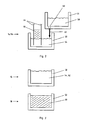
- FIG. 1 shows in a schematic representation, inter alia, a filling 10 of a crucible 50 with solid silicon 52.
- the solid silicon 52 is formed from silicon pieces of different sizes and different geometries.
- the solid silicon 52 heaped in the crucible 50 is arranged to after a melting 12 of the solid silicon 52 to achieve the highest possible level in the crucible 50.
- FIG. 1 illustrated in the middle illustration, the crucible 50 is still only partially filled with molten silicon 54 after the melting 12 of the solid silicon 52.
- liquid silicon 58 is subsequently supplied from a supply crucible 56 FIG. 1
- the device according to the invention shown in the bottom figure provides for this purpose that the storage crucible 56 is arranged at a greater height than crucible 50 and is provided with an outlet 60 which is arranged in the bottom wall of the storage bucket 56.
- the outlet 60 is designed to be closable, with the associated closure not being shown in FIG. 1 for the sake of clarity.
- the outlet 60 is arranged above the crucible 50, more precisely above the opening of the crucible 50, so that when the outlet 60 is open, the supplied silicon 62 passes into the crucible 50 as a result of the gravitational effect.
- the storage crucible 56 can in principle be arranged fixed relative to the crucible 50. Alternatively, it is conceivable that the storage crucible 56 is movable relative to the crucible 50 executed and in the in the FIG. 1 shown position can be brought.
- FIG. 2 illustrated in conjunction with FIG. 1 a method in which, as indicated by the arrow 62, liquid silicon 62 is supplied 14, while in the crucible 50 located silicon 54 is crystallized 16.
- the liquid silicon 58 is supplied from the storage crucible 56 14 (see arrow 62) while pulling wires 64 are drawn through the molten silicon 54 and supplied silicon 62.
- a silicon skin is formed between these draw wires 64, which crystallizes as silicon foil 66.
- the drawing wires 64 can be replaced by silicon thin rods, on which silicon in the crucible is crystallized according to a Czochralski drawing method.
- the invention can be used in conjunction with all crystallization processes in which a seed crystal is used.
- the invention is not limited to use in such methods, but can be used in particular in crystallization processes in which no seed crystal is used.
- FIG. 3 shows first the termination 15 of FIG. 1 At this time, the crucible 50 is almost completely filled with molten silicon 54 and supplied silicon 62. This is followed by the crystallization 18 of the liquid silicon 54 and the supplied silicon 62 follows.
- the result of this crystallization 18 shows FIG. 3 in the lower illustration, in which a crystallized in the crucible 50 silicon block 68 can be seen.
- Crystallization 18 may be accomplished, for example, by directional solidification, preferably using a planar solid-liquid phase boundary.
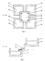
- FIG. 4 Illustrates in a plan view, on the one hand, an embodiment variant of the method according to the invention and, on the other hand, a device suitable for carrying out this embodiment variant.
- four crucibles 50a, 50b, 50c, 50d provided over which a storage crucible 56 is arranged.
- the supply crucible 56 is consequently arranged at a greater height than the four crucibles 50a, 50b, 50c, 50d.
- the storage crucible 56 is provided with outlet openings 60a, 60b, 60c, 60d, which in turn are arranged in the bottom wall of the storage bucket 56 and designed to be closable.
- the outlets 60a, 60b, 60c, 60d are arranged above the different crucibles 50a, 50b, 50a, 50d, more precisely via their openings, so that liquid silicon in the storage crucible 56 is conveyed via the outlets 60a, 60b, 60c, 60d, the various Tubs 50a, 50b, 50c, 50d can be fed.
- This supply 14 can again be effected gravitationally driven with the illustrated device.
- the storage crucible 56 may be in the in FIG. 4 shown position relative to the crucibles 50a, 50b, 50c, 50d fixed or be brought into the position shown, for example by a Schenk mechanism.
- FIG. 5 shows a further embodiment of a device.
- the storage crucible 56 is again arranged at a greater height than the one crucible 50.
- a gravitationally driven supply of liquid silicon 58 from the Supply crucible 56 to the molten silicon 54 located in the crucible 50 is possible.
- the supply takes place in the schematically illustrated embodiment of the FIG. 5 via a feed line 70 which connects the storage crucible 56 with the crucible 50.
- the arrow 62 represents the supply line 70 supplied silicon.
- the supply crucible 56 can also be arranged at the same height as the crucible 50 or below in an alternative embodiment variant.
- the supply 14 of liquid silicon 58 from the supply crucible 56 to the molten silicon 54 in the crucible 50 can nevertheless take place via the supply line 70, but a delivery device, for example a pump, is to be provided.
- FIG. 6 illustrates in a schematic partial representation of an embodiment variant of the method according to the invention, in which the solid silicon in the storage crucible 56 and the solid silicon 52 are melted in the at least one crucible with temporal overlap.
- the supply crucible is first filled with solid silicon 20. This is followed by the beginning of reflow 21 of this solid silicon in the supply crucible 56.
- At least one crucible which is embodied as a crystallization crucible in the present exemplary embodiment, is filled with solid silicon. This is followed by the beginning of the melting of the solid silicon in the crystallization crucible.
- liquid silicon is also present in the supply crucible, which can be supplied without delay to the silicon present in the crystallization crucible.
- the crucible 50, 50a, 50b, 50c, 50d may be implemented as a crystallization crucible.
- a supply 14 of liquid silicon during crystallization according to the embodiment of the FIG. 2 also in the variants of the FIGS. 4 or 5 be provided.
Landscapes
- Chemical & Material Sciences (AREA)
- Engineering & Computer Science (AREA)
- Crystallography & Structural Chemistry (AREA)
- Materials Engineering (AREA)
- Metallurgy (AREA)
- Organic Chemistry (AREA)
- Crystals, And After-Treatments Of Crystals (AREA)
- Silicon Compounds (AREA)
Description
- Die Erfindung betrifft ein Verfahren zur Bereitstellung flüssigen Siliziums gemäß dem Oberbegriff des Anspruchs 1.
- Silizium ist insbesondere als Ausgangsmaterial für die Elektronik- und Photovoltaikindustrie von großer Bedeutung. In den meisten Anwendungsfällen kann kein metallurgisches Silizium ohne weitere Vorbehandlung verwendet werden. In der Regel wird das metallurgische Silizium zunächst aufgereinigt und/oder in einer gewünschten Form kristallisiert. Beispielsweise werden polykristalline Siliziumstücke, bei Bedarf nach einer Aufreinigung des Siliziums, aufgeschmolzen und in Form monokristalliner Siliziumstäbe (sog. ingots) rekristallisiert. Hierbei kann beispielsweise das sog. Czochralski-Verfahren Verwendung finden. Alternativ wird in industriellem Umfang eine Rekristallisation in multikristallinen Siliziumblöcken oder auch sog. Siliziumfolien bzw. -bändern durchgeführt.
- In den meisten Fällen erfolgt die Rekristallisation aus der flüssigen Phase heraus. Zu diesem Zweck werden Siliziumstücke in beheizbaren Tiegeln aufgeschmolzen. Bei den Siliziumstücken kann es sich beispielsweise um zertrümmerte, nach dem Siemens-Verfahren aus der Gasphase abgeschiedene Siliziumstäbe oder metallurgisches Silizium handeln. Grundsätzlich sind alle Formen festen Siliziums verwendbar, insbesondere auch mittels eides Wirbelbettverfahrens hergestellte Siliziumkörper.
- Zum Aufschmelzen wird das feste Silizium in Tiegel eingefüllt. Dabei entstehen, je nach Form des eingesetzten Siliziums größers oder kleinere, Hohlräume. Dies führt dazu, dass nach dem Aufschmelzen des in einem voll befüllten Tiegel befindlichen festen Siliziums dieser Tiegel nur noch zu einem Teil gefüllt ist. Der Füllstand des Tiegels hat jedoch häufig Einfluss auf die Menge des in einem Verfahrenszyklus rekristallisierten Siliziums. Daher wird ein möglichst hoher Füllstand angestrebt. Zu diesem Zweck wird das feste Silizium in den Tiegeln beispielsweise gehäuft angeordnet, sodass ein Teil der Siliziumstücke über den Tiegel hinausragt. Selbst bei dieser Vorgehensweise ist der Tiegel jedoch nach Aufschmelzen des festen Siliziums üblicherweise nur noch zu 50 bis 70 % gefüllt. Aus diesem Grund wird vor der Kristallisierung in der Regel weiteres festes Silizium zu dem bereits aufgeschmolzenen Silizium zugegeben. Dies wird häufig als Nachchargieren bezeichnet.
- Das Aufschmelzen dieses nachträglich zugeführten festen Siliziums nimmt eine gewisse Zeit in Anspruch. Hinzu tritt, dass neben einem hohen Füllstand in den meisten Fällen eine homogene Siliziumschmelze erforderlich ist, um die erforderliche Güte des rekristallisierten Siliziums sicherzustellen. Bei derzeit in der industriellen Fertigung im Einsatz befindlichen Tiegeln nimmt die nachträgliche Zufuhr festen Siliziums, dessen Aufschmelzung und die Homogenisierung der Siliziumschmelze etwa zwölf Stunden in Anspruch. Gegenüber einem Verfahren, bei welchem keine nachträgliche Zufuhr festen Siliziums, also kein Nachchargieren, erforderlich ist, bedeutet dies eine Reduktion der Produktionskapazität von etwa 20 - 25 %, mit welcher der gewünschte hohe Füllstand an flüssigem Silizium erkauft wird. Nachchargierende Verfahren sind in
US 5,242,531 undEP 0 283 903 A2 beschrieben. - Vor diesem Hintergrund liegt der vorliegenden Erfindung die Aufgabe zugrunde, ein Verfahren zur Verfügung zu stellen, mit welchem aufwandsgünstig Tiegel mit einem hohen Füllstand an flüssigem Silizium bereitgestellt werden können und welches zur Herstellung blockgegossenen Siliziums geeignet ist. Diese Aufgabe wird gelöst durch ein Verfahren mit den Merkmalen des Anspruchs 1.
- Vorteilhafte Weiterbildungen sind Gegenstand abhängiger Unteransprüche.
- Der Grundgedanke des erfindungsgemäßen Verfahrens besteht darin, wenigstens einen Tiegel mit festem Silizium zu befüllen, dieses aufzuschmelzen und flüssiges Silizium zu dem in dem wenigstens einen Tiegel befindlichen Silizium zuzuführen, wobei das in dem wenigstens einen Tiegel befindliche Silizium zumindest teilweise kristallisiert wird und die Kristallisation nach der Zufuhr des flüssigen Siliziums erfolgt.
- Die Kristallisation setzt voraus, dass das in dem wenigstens einen Tiegel befindliche Silizium sich in einem flüssigen Zustand befindet, also zuvor aufgeschmolzen wurde.
- Das erfindungsgemäße Verfahren hat sich bei der Herstellung von blockgegossenen Silizium als vorteilhaft erwiesen. Die Kristallisation erfolgt nach vollständiger Zufuhr des flüssigen Siliziums, und somit weitgehendem Auffüllen des wenigstens einen Tiegels mit flüssigem Silizium, und hinreichender Homogenisierung des flüssigen Siliziums. Diese Verfahrensweise ist insbesondere anwendbar bei der Herstellung von blockgegossenem Silizium, bei dessen Erstarrung eine planare fest-flüssig-Phasengrenze durch die Siliziumschmelze geführt wird.
- Durch die Zufuhr flüssigen Siliziums entfällt der Zeitaufwand für das Aufschmelzen zugeführten Siliziums. Gegenüber einer Zufuhr und Aufschmelzung festen Siliziums gemäß dem Stand der Technik kann bei Einsatz derzeit üblicher Tiegel eine Zeitersparnis von bis zu 10 Stunden erzielt werden.
- Die Zufuhr des flüssigen Siliziums kann grundsätzlich zu jedem Zeitpunkt erfolgen, zu welchem das in dem wenigstens einen Tiegel befindliche feste Silizium zumindest teilweise bereits geschmolzen wurde. Bevorzugt erfolgt die Zufuhr flüssigen Siliziums jedoch erst, nachdem das zuvor in den wenigstens einen Tiegel eingefüllte feste Silizium vollständig geschmolzen wurde.
- Eine Ausgestaltungsvariante des erfindungsgemäßen Verfahrens sieht vor, dass das flüssige Silizium aus einem Vorratsbehälter zugeführt wird. Dieser ist vorzugsweise gegenüber der Umgebung thermisch isoliert und/oder mit einer Heizeinrichtung versehen.
- Bei einer Weiterbildung der Erfindung wird als Vorratsbehälter ein Vorratstiegel verwendet, in welchem festes Silizium aufgeschmolzen wird. Dieses aufgeschmolzene Silizium stellt sodann das flüssige Silizium dar, welches dem wenigstens einen Tiegel zuführbar ist. Der Vorratstiegel kann grundsätzlich baugleich zu dem wenigstens einen Tiegel ausgeführt sein oder sich von diesem in seiner baulichen Ausgestaltung unterscheiden.
- Vorteilhafterweise werden das feste Silizium in dem Vorratstiegel und das feste Silizium in dem wenigstens einen Tiegel mit zeitlichem Überlapp aufgeschmolzen. Es existiert somit ein Zeitraum, in welchem sowohl in dem wenigstens einen Tiegel als auch in dem Vorratstiegel jeweils Silizium in fester und flüssiger Phase vorliegt. Bei einer vorteilhaften Ausgestaltungsvariante wird der zeitliche Überlapp derart gewählt, dass zum Zeitpunkt der vollständigen Verflüssigung des in dem wenigstens einen Tiegel befindlichen Siliziums auch das in dem Vorratstiegel befindliche Silizium vollständig verflüssigt ist.
- In der Praxis hat es sich bewährt, mindestens zwei Tiegel vorzusehen, welche anfänglich mit festen Silizium befüllt werden. Insbesondere eine Zahl von vier Tiegeln hat sich bewährt. Vorteilhafterweise wird den mindestens zwei Tiegeln flüssiges Silizium aus demselben Vorratsbehälter zugeführt.
- Vorteilhafterweise wird den mindestens zwei Tiegeln gleichzeitig flüssiges Silizium zugeführt. Das zugeführte Silizium kann dabei grundsätzlich aus verschiedenen Vorratsbehältern zugeführt werden. Als besonders vorteilhaft hat es sich jedoch erwiesen, den mindestens zwei Tiegeln gleichzeitig flüssiges Silizium aus demselben Vorratsbehälter zuzuführen.
- Alternativ kann den mindestens zwei Tiegeln flüssiges Silizium mit zeitlichem Versatz zugeführt werden. In dieser Weise lässt sich eine serielle Befüllung der mindestens zwei Tiegel realisieren. Das zugeführte Silizium kann dabei wiederum aus verschiedenen oder demselben Vorratsbehälter zugeführt werden.
- Abweichend von der Erfindung kann flüssiges Silizium zugeführt werden, während in dem wenigstens einen Tiegel befindliches Silizium kristallisiert wird. Dies kann beispielsweise der Fall sein, wenn die Kristallisation durch das Ziehen von Siliziumfolien bzw. Siliziumbändern erfolgt. Hierfür sind verschiedene Technologien bekannt. Beispielsweise werden Ziehdrähte durch die Schmelze gezogen, zwischen welchen sich eine Siliziumhaut ausbildet, welche im Weiteren erstarrt. Die Kristallisation kann in einem anderen Beispiel in Form von Siliziumstäben (ingots) erfolgen, beispielsweise mittels eines Czochralski-Verfahrens.
- Sofern die Kristallisation des flüssigen Siliziums in dem wenigstens einen Tiegel erfolgt, oder unmittelbar aus dem wenigstens einen Tiegel hinaus wie beim Folienziehen, so wird vorzugsweise der wenigstens eine Tiegel als Kristallisationstiegel ausgebildet. D. h. es wird ein Tiegel verwendet, der beispielsweise mit speziellen Beschichtungen wie Siliziumnitrit oder Graphit versehen ist, um die Gefahr eines Verunreinigungseintrages zu verringern. Je nach dem verwendeten Kristallisationsverfahren können die Kristallisationstiegel andere oder zusätzliche spezielle Eigenschaften aufweisen.
- Eine Vorrichtung zur Durchführung des erfindungsgemäßen Verfahrens sieht wenigstens einen beheizbaren Tiegel zum Aufschmelzen festen Siliziums und wenigstens einen Vorratsbehälter für flüssiges Silizium vor. Dabei ist flüssiges Silizium aus dem Vorratsbehälter dem wenigstens einen Tiegel zuführbar.
- Bei einer Weiterbildung dieser Vorrichtung ist der Vorratsbehälter als beheizbarer Vorratstiegel ausgeführt, in welchem festes Silizium aufschmelzbar ist.
- Bevorzugt ist der wenigstens eine beheizbare Tiegel durch mindestens zwei Tiegel gebildet. Auf diese Weise ist eine rationellere Durchführung des Verfahrens möglich.
- Eine Weiterbildung der Vorrichtung sieht ferner vor, dass flüssiges Silizium aus dem Vorratsbehälter den mindestens zwei Tiegeln gleichzeitig zuführbar ist.
- Bei einer Ausführungsvariante der Vorrichtung ist der wenigstens eine Tiegel als Kristallisationstiegel ausgeführt. Kristallisationstiegel sind üblicherweise auf den jeweiligen Kristallisationsprozess angepasst und beispielsweise, wie oben dargelegt, mit speziellen Beschichtungen versehen. Weiterhin können aufwändige Heizeinrichtungen und zugehörige Steuerungen und Regelungen vorgesehen sein, welche den Fertigungsaufwand eines Kristallisationstiegels gegenüber einem gewöhnlichen Schmelztiegel signifikant erhöhen. Dennoch kann auch der Vorratsbehälter als Kristallisationstiegel ausgeführt sein, selbst wenn in diesem keine Kristallisation erfolgt. Aus Kostengründen wird jedoch der Vorratstiegel bevorzugt aufwandsgünstiger ausgestaltet. Beispielsweise können Steuerungen und Regelungen für Heizeinrichtungen aufwandsgünstiger ausgeführt sein. Je nach gewünschtem Reinheitsgrad des zugeführten flüssigen Siliziums ist auch eine Vereinfachung der Beschichtungen oder die Wahl günstigerer Materialien für die Ausbildung des Vorratstiegels denkbar.
- Eine vorteilhafte Ausführungsvariante sieht vor, dass der Vorratsbehälter in größerer Höhe als der wenigstens eine Tiegel derart angeordnet ist, sodass flüssiges Silizium aus dem Vorratsbehälter dem wenigstens einen Tiegel gravitationsgetrieben zuführbar ist. Dies ermöglicht einen Verzicht auf aufwändige Fördereinrichtungen für flüssiges Silizium.
- Vorteilhafterweise ist der Vorratsbehälter mit wenigstens einem Auslass versehen und derart relativ zu dem wenigstens einen Tiegel anordenbar, dass diesem flüssiges Silizium über den wenigstens einen Auslass zuführbar ist. Die konkrete Ausgestaltung des Auslasses ist grundsätzlich frei wählbar. Beispielweise kann der Auslass durch eine verschließbare Öffnung in der Bodenwandung des Vorratsbehälters gebildet sein, wobei diese Öffnung sodann vertikal über dem wenigstens einen Tiegel anordenbar wäre.
- Eine weitere Ausgestaltungsvariante sieht vor, dass der Vorratsbehälter mit dem wenigstens einen Tiegel über wenigstens eine Zuleitung verbunden ist, mittels welcher flüssiges Silizium aus dem Vorratsbehälter dem wenigstens einen Tiegel zuführbar ist. Eine derartige Zuleitung kann beispielsweise in einen Auslass des Vorratsbehälters münden. Die Zufuhr des flüssigen Siliziums über die Zuleitung kann dabei mittels einer Fördereinrichtung, beispielsweise einer Pumpe, erfolgen. Eine gravitationsgetriebene Zufuhr ist offensichtlich ebenfalls denkbar.
- Im Folgenden wird die Erfindung anhand von Figuren näher erläutert. Soweit zweckdienlich, sind hierin gleichwirkende Elemente mit gleichen Bezugszeichen versehen. Es zeigen:
- Figur 1:
- Schematische Darstellung eines ersten Teils eines Ausführungsbeispiels eines erfindungsgemäßen Verfahrens sowie Prinzipdarstellung einer ersten Ausgestaltungsvariante einer Vorrichtung zu dessen Durchführung.
- Figur 2:
- Schematische Darstellung einer Verfahrensvariante, bei welchem eine Kristallisation bei gleichzeitiger Zufuhr flüssigen Siliziums erfolgt.
- Figur 3:
- Schematische Darstellung eines zweiten Teils des Ausführungsbeispiels des erfindungsgemäßen Verfahrens.
- Figur 4:
- Prinzipdarstellung eines erfindungsgemäßen Verfahrens, bei welchem flüssiges Silizium mehreren Tiegeln gleichzeitig zugeführt wird, sowie schematische Darstellung einer hierzu geeigneten Vorrichtung.
- Figur 5:
- Schematische Darstellung eines weiteren Ausführungsbeispiels einer geeigneten Vorrichtung.
- Figur 6:
- Schematische Teildarstellung eines weiteren Ausführungsbeispiels des erfindungsgemäßen Verfahrens.
-
Figur 1 zeigt in schematischer Darstellung unter anderem ein Befüllen 10 eines Tiegels 50 mit festen Silizium 52. Das feste Silizium 52 ist dabei aus Siliziumstücken verschiedener Größen und verschiedener Geometrien gebildet. WieFigur 1 zeigt, ist das feste Silizium 52 gehäuft in dem Tiegel 50 angeordnet, um nach einem Aufschmelzen 12 des festen Siliziums 52 eine möglichst hohen Füllstand in dem Tiegel 50 zu erreichen. - Wie
Figur 1 in der mittleren Darstellung illustriert, ist der Tiegel 50 dennoch nach dem Aufschmelzen 12 des festen Siliziums 52 nur teilweise mit aufgeschmolzenem Silizium 54 gefüllt. Infolgedessen wird im Weiteren flüssiges Silizium 58 aus einem Vorratstiegel 56 zugeführt 14. Die inFigur 1 in der untersten Abbildung dargestellte erfindungsgemäße Vorrichtung sieht zu diesem Zweck vor, dass der Vorratstiegel 56 in größerer Höhe als Tiegel 50 angeordnet ist und mit einem Auslass 60 versehen ist, welcher in der Bodenwandung des Vorratstiegels 56 angeordnet ist. Der Auslass 60 ist verschließbar ausgeführt, wobei der besseren Übersicht halber der zugehörige Verschluss in Figur 1 nicht dargestellt ist. Ferner ist der Auslass 60 über dem Tiegel 50, genauer über der Öffnung des Tiegels 50, angeordnet, sodass bei geöffnetem Auslass 60 das zugeführte Silizium 62 infolge der Gravitationswirkung in den Tiegel 50 gelangt. - Der Vorratstiegel 56 kann grundsätzlich fest relativ zu dem Tiegel 50 angeordnet sein. Alternativ ist denkbar, dass der Vorratstiegel 56 beweglich relativ zu dem Tiegel 50 ausgeführt und in die in der
Figur 1 dargestellte Position verbringbar ist. -
Figur 2 illustriert in Verbindung mitFigur 1 ein Verfahren, in welchem, wie durch den Pfeil 62 angedeutet, flüssiges Silizium 62 zugeführt wird 14, während in dem Tiegel 50 befindliches Silizium 54 kristallisiert wird 16. Anstelle der in Figur 1 dargestellten schlichten Zufuhr flüssigen Siliziums wird im Ausführungsbeispiel derFigur 2 im Anschluss an das Befüllen 10 des Tiegels und das Aufschmelzen 12 des festen Siliziums 52 das flüssige Silizium 58 aus dem Vorratstiegel 56 zugeführt 14 (vgl. Pfeil 62), während Ziehdrähte 64 durch das aufgeschmolzene Silizium 54 und zugeführtes Silizium 62 gezogen werden. Dabei wird zwischen diesen Ziehdrähten 64 eine Siliziumhaut ausgebildet, welche als Siliziumfolie 66 kristallisiert. - In einer anderen Ausgestaltungsvariante können die Ziehdrähte 64 durch Siliziumdünnstäbe ersetzt werden, an welchen in dem Tiegel befindliches Silizium gemäß einem Czochralski-Ziehverfahren kristallisiert wird. Grundsätzlich kann die Erfindung in Verbindung mit allen Kristallisierungsverfahren verwendet werden, bei welchem ein Keimkristall verwendet wird. Die Erfindung ist jedoch nicht auf die Verwendung bei derartigen Verfahren beschränkt, sondern kann insbesondere auch bei Kristallisationsverfahren zur Anwendung kommen, bei welchem kein Keimkristall eingesetzt wird.
- Bei dem erfindungsgemäßen Verfahren erfolgt die Kristallisation erst nach der Zufuhr 14 des flüssigen Siliziums 58. Ein Ausführungsbeispiel solch eines Verfahrens illustriert
Figur 3 in Verbindung mitFigur 1 .Figur 3 zeigt zunächst die Beendigung 15 derFigur 1 dargestellten Zufuhr 14 flüssigen Siliziums 58 aus dem Vorratstiegel 56. Zu diesem Zeitpunkt ist der Tiegel 50 nahezu vollständig gefüllt mit aufgeschmolzenem Silizium 54 und zugeführtem Silizium 62. Hieran schließt sich die Kristallisation 18 des flüssigen Siliziums 54 und des zugeführten Siliziums 62 an. Das Ergebnis dieser Kristallisation 18 zeigtFigur 3 in der unteren Darstellung, in welcher ein in dem Tiegel 50 kristallisierter Siliziumblock 68 erkennbar ist. Die Kristallisation 18 kann beispielsweise mittels gerichteter Erstarrung erfolgen, vorzugsweise unter Verwendung einer planaren fest-flüssig-Phasengrenze. -
Figur 4 illustriert in einer Aufsicht einerseits eine Ausführungsvariante des erfindungsgemäßen Verfahrens, zum anderen eine zur Durchführung dieser Ausführungsvariante geeignete Vorrichtung. So sind in der Darstellung derFigur 4 vier Tiegel 50a, 50b, 50c, 50d vorgesehen, über welchen eine Vorratstiegel 56 angeordnet ist. Der Vorratstiegel 56 ist demzufolge in größerer Höhe angeordnet als die vier Tiegel 50a, 50b, 50c, 50d. Der Vorratstiegel 56 ist mit Auslassöffnungen 60a, 60b, 60c, 60d versehen, welche wiederum in der Bodenwandung des Vorratstiegels 56 angeordnet und verschließbar ausgeführt sind. Die Auslässe 60a, 60b, 60c, 60d sind dabei über den verschiedenen Tiegeln 50a, 50b, 50a, 50d angeordnet, genauer über deren Öffnungen, sodass in dem Vorratstiegel 56 befindliches flüssiges Silizium über die Auslässe 60a, 60b, 60c, 60d, den verschiedenen Tiegeln 50a, 50b, 50c, 50d zuführbar ist. Diese Zufuhr 14 kann mit der dargestellten Vorrichtung wiederum gravitations-getrieben erfolgen. Der Vorratstiegel 56 kann in der inFigur 4 dargestellten Position relativ zu den Tiegeln 50a, 50b, 50c, 50d fixiert oder in die dargestellte Position verbringbar sein, beispielsweise durch einen Schenkmechanismus. - Unter der Annahme, dass die Auslässe 60a, 60b, 60c, 60d geöffnet sind illustriert
Figur 4 somit auch ein Zuführen 14 des flüssigen Siliziums 58 aus dem Vorratstiegel 56 zudem in den Tiegeln 50a, 50b, 50c, 50d befindlichen Silizium 54. Den vier Tiegeln 50, 50b, 50c, 50d wird dabei offensichtlich gleichzeitig flüssiges Silizium 58 aus demselben Vorratsbehälter 56 zugeführt. -
Figur 5 zeigt ein weiteres Ausführungsbeispiel einer Vorrichtung. Bei dieser ist der Vorratstiegel 56 wiederum in größerer Höhe angeordnet als der eine Tiegel 50. somit ist erneut eine gravitationsgetriebene Zufuhr flüssigen Siliziums 58 aus dem Vorratstiegel 56 zu dem in dem Tiegel 50 befindlichem aufgeschmolzenen Silizium 54 möglich. Die Zufuhr erfolgt in der schematisch dargestellten Ausführungsvariante derFigur 5 über eine Zuleitung 70, welche den Vorratstiegel 56 mit dem Tiegel 50 verbindet. Der Pfeil 62 stellt das über die Zuleitung 70 zugeführte Silizium dar. - Entgegen der Darstellung der
Figur 5 kann der Vorratstiegel 56 in einer alternativen Ausgestaltungsvariante auch auf gleicher Höhe wie der Tiegel 50 oder darunter angeordnet werden. Die Zufuhr 14 flüssige Siliziums 58 aus dem Vorratstiegel 56 zu dem aufgeschmolzenen Silizium 54 in dem Tiegel 50 kann dennoch über die Zuleitung 70 erfolgen, jedoch ist eine Fördereinrichtung, beispielsweise eine Pumpe, vorzusehen. -
Figur 6 illustriert in einer schematischen Teildarstellung eine Ausgestaltungsvariante des erfindungsgemäßen Verfahrens, bei welchem das feste Silizium in dem Vorratstiegel 56 und das feste Silizium 52 in dem wenigstens einen Tiegel mit zeitlichem Überlapp aufgeschmolzen werden. Hierzu wird zunächst der Vorratstiegel mit festem Silizium befüllt 20. Hieran schließt sich der Beginn des Aufschmelzens 21 dieses festen Siliziums im Vorratstiegel 56 an. - Im Folgenden wird der im vorliegenden Ausführungsbeispiel als Kristallisationstiegel ausgeführte wenigstens eine Tiegel mit festem Silizium befüllt 10. Hieran schließt sich der Beginn 11 des Aufschmelzens des festen Siliziums im Kristallisationstiegel an.
- Im Weiteren wird eine vollständige verflüssigung 23 des im Vorratstiegel befindlichen Siliziums erreicht, ehe eine vollständige Verflüssigung 13 des im Kristallisationstiegel befindlichen Siliziums erzielt wird.
- Auf diese Weise liegt zum Zeitpunkt der vollständigen Verflüssigung 13 des im Kristallisationstiegel befindlichen Siliziums auch im Vorratstiegel flüssiges Silizium vor, welches verzögerungsfrei dem im Kristallisationstiegel befindlichen Silizium zugeführt 24 werden kann.
- Je nach den Anforderungen des jeweiligen Anwendungsfalls können offensichtlich die in den Ausführungsbeispielen der
Figuren 1 bis 6 dargestellten Weiterbildungen in geeigneter Weise miteinander kombiniert werden. Beispielsweise kann in jedem der dargestellten Ausführungsbeispiele der Tiegel 50, 50a, 50b, 50c, 50d als Kristallisationstiegel ausgeführt sein. Weiterhin kann eine Zufuhr 14 flüssigen Siliziums während der Kristallisation entsprechend dem Ausführungsbeispiel derFigur 2 auch in den Ausführungsvarianten derFiguren 4 oder 5 vorgesehen werden. Des Weiteren ist insbesondere eine Durchführung des Verfahrens gemäß der Darstellung in derFigur 6 mit allen in denFiguren 1 bis 5 dargestellten erfindungsgemäßen Vorrichtungen möglich. -
- 10
- Befüllen des Tiegels
- 11
- Beginn Aufschmelzen Silizium in Kristallisationstiegel
- 12
- Aufschmelzen des festen Siliziums
- 13
- Vollständige Verflüssigung Silizium in Kristallisations- tiegel
- 14
- Zuführen flüssigen Siliziums
- 15
- Beendigung der Zufuhr flüssigen Siliziums
- 16
- Kristallisieren flüssigen Siliziums
- 18
- Kristallisieren flüssigen Siliziums
- 20
- Befüllen Vorratstiegel
- 21
- Beginn Aufschmelzen Silizium in Vorratstiegel
- 23
- Vollständige Verflüssigung Silizium in Vorratstiegel
- 24
- Zuführen flüssigen Silizium aus Vorratstiegel
- 50
- Tiegel
- 50a
- Tiegel
- 50b
- Tiegel
- 50c
- Tiegel
- 50d
- Tiegel
- 52
- festes Silizium
- 54
- aufgeschmolzenes Silizium
- 56
- Vorratstiegel
- 58
- flüssiges Silizium
- 60
- Auslass
- 60a
- Auslass
- 60b
- Auslass
- 60c
- Auslass
- 60d
- Auslass
- 62
- zugeführtes Silizium
- 64
- Ziehdrähte
- 66
- kristallisierte Siliziumfolie
- 68
- kristallisierter Siliziumblock
- 70
- Zuleitung
Claims (6)
- Verfahren zur Bereitstellung flüssigen Siliziums aufweisend die Verfahrensschritte des- Befüllens (10) wenigstens eines Tiegels (50; 50a, 50b, 50c, 50d) mit festem Silizium (52),- des Aufschmelzens (12) des in dem wenigstens einen Tiegel (50; 50a, 50b, 50c, 50d) befindlichen festen Siliziums (52),- des Zufuhren (14; 24) flüssigen Siliziums (58) zu dem in dem wenigstens einen Tiegel (50; 50a, 50b, 50c, 50d) befindlichen Silizium (54) und- des zumindest teilweisen Kristallisierens (16; 18) des in dem wenigstens einen Tiegel (50; 50a, 50b, 50c, 50d) befindlichen Siliziums (54, 62),dadurch gekennzeichnet,
dass die Kristallisation (18) nach der Zufuhr (14) des flüssigen Siliziums (58) erfolgt. - Verfahren nach Anspruch 1,
dadurch gekennzeichnet,
dass das flüssige Silizium (58) aus einem Vorratsbehälter (56) zugeführt wird (14; 24) und als Vorratsbehälter (56) ein Vorratstiegel (56) verwendet wird, in welchem festes Silizium aufgeschmolzen wird (21, 23). - Verfahren nach Anspruch 2,
dadurch gekennzeichnet,
dass da3 feste Silizium in dem Vorratstiegel (56) und dass feste Silizium (52) in dem wenigstens einen Tiegel (50; 50a, 50b, 50c, 50d) mit zeitlichem Überlapp aufgeschmolzen werden (11, 13, 21, 23), wobei der zeitliche Überlapp bevorzugt derart gewählt wird, dass zum Zeitpunkt der vollständigen Verflüssigung (13) des in dem wenigstens einen Tiegel (50) befindlichen Siliziums (52) auch das in dem Vorratstiegel (56) befindliche Silizium vollständig verflüssigt ist (23). - Verfahren nach einem der vorangegangenen Ansprüche,
dadurch gekennzeichnet,
dass mindestens zwei Tiegel (50a, 50b, 50c, 50d) vorgesehen werden, vorzugsweise vier. - Verfahren nach Anspruch 4,
dadurch gekennzeichnet,
dass den mindestens zwei Tiegeln (50a, 50b, 50c, 50d) gleichzeitig flüssiges Silizium (58) zugeführt wird (14). - Verfahren nach Anspruch 4,
dadurch gekennzeichnet,
dass den mindestens zwei Tiegeln (50a, 50b, 50c, 50d) gleichzeitig flüssiges Silizium (58) aus demselben Vorratsbehälter (56) zugeführt wird.
Applications Claiming Priority (1)
| Application Number | Priority Date | Filing Date | Title |
|---|---|---|---|
| DE102009021003A DE102009021003A1 (de) | 2009-05-12 | 2009-05-12 | Verfahren und Vorrichtung zur Bereitstellung flüssigen Siliziums |
Publications (2)
| Publication Number | Publication Date |
|---|---|
| EP2251459A1 EP2251459A1 (de) | 2010-11-17 |
| EP2251459B1 true EP2251459B1 (de) | 2012-08-22 |
Family
ID=42542977
Family Applications (1)
| Application Number | Title | Priority Date | Filing Date |
|---|---|---|---|
| EP10005022A Not-in-force EP2251459B1 (de) | 2009-05-12 | 2010-05-12 | Verfahren und Vorrichtung zur Bereitstellung flüssigen Siliziums |
Country Status (3)
| Country | Link |
|---|---|
| US (1) | US20100290973A1 (de) |
| EP (1) | EP2251459B1 (de) |
| DE (1) | DE102009021003A1 (de) |
Families Citing this family (1)
| Publication number | Priority date | Publication date | Assignee | Title |
|---|---|---|---|---|
| DE102013203740B4 (de) * | 2013-03-05 | 2020-06-18 | Solarworld Industries Gmbh | Vorrichtung und Vefahren zur Herstellung von Silizium-Blöcken |
Family Cites Families (40)
| Publication number | Priority date | Publication date | Assignee | Title |
|---|---|---|---|---|
| US3206286A (en) * | 1959-07-23 | 1965-09-14 | Westinghouse Electric Corp | Apparatus for growing crystals |
| US3658119A (en) * | 1968-04-03 | 1972-04-25 | Airco Inc | Apparatus for processing molten metal in a vacuum |
| US3917241A (en) * | 1973-01-15 | 1975-11-04 | Lectromelt Corp | Molten metal holding furnace system |
| DE2745247C3 (de) * | 1977-10-07 | 1980-03-13 | Wacker-Chemitronic Gesellschaft Fuer Elektronik-Grundstoffe Mbh, 8263 Burghausen | Verfahren und Vorrichtung zur semikontinuierlichen Herstellung von Siliciumformkörpern |
| DE2903061A1 (de) * | 1979-01-26 | 1980-08-07 | Heliotronic Gmbh | Verfahren zur herstellung grosskristalliner vorzugsorientierter siliciumfolien |
| DE2925679A1 (de) * | 1979-06-26 | 1981-01-22 | Heliotronic Gmbh | Verfahren zur herstellung von siliciumstaeben |
| US4396824A (en) * | 1979-10-09 | 1983-08-02 | Siltec Corporation | Conduit for high temperature transfer of molten semiconductor crystalline material |
| US4454096A (en) * | 1981-06-15 | 1984-06-12 | Siltec Corporation | Crystal growth furnace recharge |
| EP0221051A1 (de) * | 1985-04-16 | 1987-05-13 | Energy Materials Corporation | Verfahren und vorrichtung zum wachsen von monokristallen |
| JPH0733305B2 (ja) * | 1987-03-20 | 1995-04-12 | 三菱マテリアル株式会社 | 石英製二重ルツボの製造方法 |
| DE3736453A1 (de) * | 1987-10-28 | 1989-05-11 | Schwaebische Huettenwerke Gmbh | Verfahren zur herstellung einer nockenwelle |
| US5245531A (en) * | 1989-03-10 | 1993-09-14 | Kabushiki Kaisha Toshiba | Multiplexed digital control device |
| US5269785A (en) * | 1990-06-28 | 1993-12-14 | Bonutti Peter M | Apparatus and method for tissue removal |
| US6990982B1 (en) * | 1990-06-28 | 2006-01-31 | Bonutti Ip, Llc | Method for harvesting and processing cells from tissue fragments |
| DE4106589C2 (de) * | 1991-03-01 | 1997-04-24 | Wacker Siltronic Halbleitermat | Kontinuierliches Nachchargierverfahren mit flüssigem Silicium beim Tiegelziehen nach Czochralski |
| DE4128325A1 (de) * | 1991-08-27 | 1993-03-04 | Bayer Ag | Verfahren zur herstellung von silicium sowie vorrichtung zu dessen durchfuehrung |
| US5526822A (en) * | 1994-03-24 | 1996-06-18 | Biopsys Medical, Inc. | Method and apparatus for automated biopsy and collection of soft tissue |
| DE19635593C1 (de) * | 1996-09-02 | 1998-04-23 | Siemens Ag | Ultraschallwandler für den diagnostischen und therapeutischen Einsatz |
| JPH10158088A (ja) * | 1996-11-25 | 1998-06-16 | Ebara Corp | 固体材料の製造方法及びその製造装置 |
| US6489706B2 (en) * | 1998-11-13 | 2002-12-03 | Acuson Corporation | Medical diagnostic ultrasound transducer and method of manufacture |
| US6086544A (en) * | 1999-03-31 | 2000-07-11 | Ethicon Endo-Surgery, Inc. | Control apparatus for an automated surgical biopsy device |
| US6602203B2 (en) * | 2000-10-13 | 2003-08-05 | Ethicon Endo-Surgery, Inc. | Remote thumbwheel for a surgical biopsy device |
| EP1254861B1 (de) * | 2000-12-28 | 2008-01-30 | Sumco Corporation | Kontinuierliches giessverfahren für silizium |
| US20040078090A1 (en) * | 2002-10-18 | 2004-04-22 | Francois Binette | Biocompatible scaffolds with tissue fragments |
| US7115100B2 (en) * | 2002-11-15 | 2006-10-03 | Ethicon, Inc. | Tissue biopsy and processing device |
| US7794408B2 (en) * | 2003-03-28 | 2010-09-14 | Ethicon, Inc. | Tissue collection device and methods |
| US10583220B2 (en) * | 2003-08-11 | 2020-03-10 | DePuy Synthes Products, Inc. | Method and apparatus for resurfacing an articular surface |
| US8034003B2 (en) * | 2003-09-11 | 2011-10-11 | Depuy Mitek, Inc. | Tissue extraction and collection device |
| US7611473B2 (en) * | 2003-09-11 | 2009-11-03 | Ethicon, Inc. | Tissue extraction and maceration device |
| US7316822B2 (en) * | 2003-11-26 | 2008-01-08 | Ethicon, Inc. | Conformable tissue repair implant capable of injection delivery |
| US8673021B2 (en) * | 2003-11-26 | 2014-03-18 | Depuy Mitek, Llc | Arthroscopic tissue scaffold delivery device |
| US7901461B2 (en) * | 2003-12-05 | 2011-03-08 | Ethicon, Inc. | Viable tissue repair implants and methods of use |
| US7344594B2 (en) * | 2004-06-18 | 2008-03-18 | Memc Electronic Materials, Inc. | Melter assembly and method for charging a crystal forming apparatus with molten source material |
| KR101470814B1 (ko) * | 2006-01-20 | 2014-12-09 | 에이엠지 아이디얼캐스트 솔라 코포레이션 | 광전 변환 소자용 단결정 캐스트 실리콘 및 단결정 캐스트 실리콘 바디들을 제조하는 방법 및 장치 |
| US9345457B2 (en) * | 2006-12-13 | 2016-05-24 | Devicor Medical Products, Inc. | Presentation of biopsy sample by biopsy device |
| JP2008289599A (ja) * | 2007-05-23 | 2008-12-04 | Toshiba Corp | 超音波プローブと、超音波診断装置 |
| WO2008157059A1 (en) * | 2007-06-15 | 2008-12-24 | Ethicon, Inc. | Tissue fragment compositions for the treatment of incontinence |
| US7834522B2 (en) * | 2007-08-03 | 2010-11-16 | Mr Holdings (Hk) Limited | Diagnostic ultrasound transducer |
| DE102007039434A1 (de) * | 2007-08-21 | 2009-02-26 | Prüftechnik Dieter Busch AG | Verfahren und Vorrichtung zum Erfassen von Partikeln in einer strömenden Flüssigkeit |
| US20100160819A1 (en) * | 2008-12-18 | 2010-06-24 | Parihar Shailendra K | Biopsy Device with Central Thumbwheel |
-
2009
- 2009-05-12 DE DE102009021003A patent/DE102009021003A1/de not_active Ceased
-
2010
- 2010-05-12 EP EP10005022A patent/EP2251459B1/de not_active Not-in-force
- 2010-05-12 US US12/778,423 patent/US20100290973A1/en not_active Abandoned
Also Published As
| Publication number | Publication date |
|---|---|
| DE102009021003A1 (de) | 2010-11-18 |
| EP2251459A1 (de) | 2010-11-17 |
| US20100290973A1 (en) | 2010-11-18 |
Similar Documents
| Publication | Publication Date | Title |
|---|---|---|
| DE944209C (de) | Verfahren zur Herstellung von Halbleiterkoerpern | |
| EP2379783B1 (de) | Verfahren und vorrichtung zur herstellung von siliziumdünnstäben | |
| DE112015003573T5 (de) | Verfahren zum Steuern des spezifischen Widerstands und N-Silicium-Einkristall | |
| DE4106589A1 (de) | Kontinuierliches nachchargierverfahren mit fluessigem silicium beim tiegelziehen nach czochralski | |
| DE112016004193B4 (de) | Verfahren zum Herstellen eines Einkristalls | |
| EP2890834B1 (de) | Modellprädiktive regelung des zonenschmelz-verfahrens | |
| EP2242874B1 (de) | Vorrichtung und verfahren zur herstellung von kristallinen körpern durch gerichtete erstarrung | |
| DE10137856A1 (de) | Durch tiegelloses Zonenziehen hergestellter Einkristall aus Silicium | |
| EP1004374A1 (de) | Druckgiessverfahren zur Herstellung von Gussstücken aus Legierungen mit thixotropen Eigenschaften | |
| DE3325242C2 (de) | Verfahren und Vorrichtung zum Ziehen eines Verbindungshalbleiter-Einkristalls | |
| DE3333960A1 (de) | Verfahren zur herstellung von versetzungsfreien einkristallstaeben aus silicium | |
| DE102010014110B4 (de) | Verfahren zur Herstellung eines Halbleiter-Einkristalls | |
| DE19700403B4 (de) | Einkristallziehvorrichtung | |
| EP2251459A1 (de) | Verfahren und Vorrichtung zur Bereitstellung flüssigen Siliziums | |
| EP3280557A1 (de) | Stranggiessen mit optimierter oszillation der stranggiesskokille | |
| DE2358300A1 (de) | Verfahren und vorrichtung zum tiegelfreien zonenschmelzen eines halbleiterkristallstabes | |
| WO2020201399A1 (de) | Verfahren zur herstellung eines snbi-lötdrahtes, lötdraht und vorrichtung | |
| EP3034658B1 (de) | Verfahren zum züchten eines einkristalls durch kristallisieren des einkristalls aus einer fliesszone | |
| DE112009000255T5 (de) | Silizium-Einkristall | |
| DE102011077862A1 (de) | System und Verfahren zum Zuführen eines Ausgangsmaterials in eine Schmelze zur Herstellung eines einkristallinen Werkstoffs | |
| WO2019011776A1 (de) | Verfahren und anlage zur herstellung von gussblöcken aus metall | |
| DE102008062049A1 (de) | Silicium-Einkristalle mit niedriger Sauerstoffkonzentration sowie deren Herstellung | |
| DE102008030311B4 (de) | Verfahren und Vorrichtung zur Herstellung eines Einkristalls, insbesondere eines Silizium-Einkristalls, und Schmelzstab hierfür | |
| DE2060673C3 (de) | Vorrichtung zur Herstellung von Phosphiden | |
| CH445132A (de) | Verfahren zum Reinigen von geschmolzenem unreinem Aluminium durch Entfernen von darin enthaltenen Verunreinigungen |
Legal Events
| Date | Code | Title | Description |
|---|---|---|---|
| PUAI | Public reference made under article 153(3) epc to a published international application that has entered the european phase |
Free format text: ORIGINAL CODE: 0009012 |
|
| AK | Designated contracting states |
Kind code of ref document: A1 Designated state(s): AL AT BE BG CH CY CZ DE DK EE ES FI FR GB GR HR HU IE IS IT LI LT LU LV MC MK MT NL NO PL PT RO SE SI SK SM TR |
|
| AX | Request for extension of the european patent |
Extension state: BA ME RS |
|
| 17P | Request for examination filed |
Effective date: 20110517 |
|
| GRAP | Despatch of communication of intention to grant a patent |
Free format text: ORIGINAL CODE: EPIDOSNIGR1 |
|
| GRAS | Grant fee paid |
Free format text: ORIGINAL CODE: EPIDOSNIGR3 |
|
| GRAA | (expected) grant |
Free format text: ORIGINAL CODE: 0009210 |
|
| AK | Designated contracting states |
Kind code of ref document: B1 Designated state(s): AL AT BE BG CH CY CZ DE DK EE ES FI FR GB GR HR HU IE IS IT LI LT LU LV MC MK MT NL NO PL PT RO SE SI SK SM TR |
|
| REG | Reference to a national code |
Ref country code: GB Ref legal event code: FG4D Free format text: NOT ENGLISH |
|
| REG | Reference to a national code |
Ref country code: CH Ref legal event code: EP |
|
| REG | Reference to a national code |
Ref country code: IE Ref legal event code: FG4D Free format text: LANGUAGE OF EP DOCUMENT: GERMAN |
|
| REG | Reference to a national code |
Ref country code: AT Ref legal event code: REF Ref document number: 572077 Country of ref document: AT Kind code of ref document: T Effective date: 20120915 |
|
| REG | Reference to a national code |
Ref country code: DE Ref legal event code: R096 Ref document number: 502010001091 Country of ref document: DE Effective date: 20121018 |
|
| REG | Reference to a national code |
Ref country code: NL Ref legal event code: VDEP Effective date: 20120822 |
|
| REG | Reference to a national code |
Ref country code: LT Ref legal event code: MG4D Effective date: 20120822 |
|
| PG25 | Lapsed in a contracting state [announced via postgrant information from national office to epo] |
Ref country code: NO Free format text: LAPSE BECAUSE OF FAILURE TO SUBMIT A TRANSLATION OF THE DESCRIPTION OR TO PAY THE FEE WITHIN THE PRESCRIBED TIME-LIMIT Effective date: 20121122 Ref country code: FI Free format text: LAPSE BECAUSE OF FAILURE TO SUBMIT A TRANSLATION OF THE DESCRIPTION OR TO PAY THE FEE WITHIN THE PRESCRIBED TIME-LIMIT Effective date: 20120822 Ref country code: IS Free format text: LAPSE BECAUSE OF FAILURE TO SUBMIT A TRANSLATION OF THE DESCRIPTION OR TO PAY THE FEE WITHIN THE PRESCRIBED TIME-LIMIT Effective date: 20121222 Ref country code: LT Free format text: LAPSE BECAUSE OF FAILURE TO SUBMIT A TRANSLATION OF THE DESCRIPTION OR TO PAY THE FEE WITHIN THE PRESCRIBED TIME-LIMIT Effective date: 20120822 Ref country code: HR Free format text: LAPSE BECAUSE OF FAILURE TO SUBMIT A TRANSLATION OF THE DESCRIPTION OR TO PAY THE FEE WITHIN THE PRESCRIBED TIME-LIMIT Effective date: 20120822 |
|
| PG25 | Lapsed in a contracting state [announced via postgrant information from national office to epo] |
Ref country code: LV Free format text: LAPSE BECAUSE OF FAILURE TO SUBMIT A TRANSLATION OF THE DESCRIPTION OR TO PAY THE FEE WITHIN THE PRESCRIBED TIME-LIMIT Effective date: 20120822 Ref country code: PT Free format text: LAPSE BECAUSE OF FAILURE TO SUBMIT A TRANSLATION OF THE DESCRIPTION OR TO PAY THE FEE WITHIN THE PRESCRIBED TIME-LIMIT Effective date: 20121224 Ref country code: GR Free format text: LAPSE BECAUSE OF FAILURE TO SUBMIT A TRANSLATION OF THE DESCRIPTION OR TO PAY THE FEE WITHIN THE PRESCRIBED TIME-LIMIT Effective date: 20121123 Ref country code: SE Free format text: LAPSE BECAUSE OF FAILURE TO SUBMIT A TRANSLATION OF THE DESCRIPTION OR TO PAY THE FEE WITHIN THE PRESCRIBED TIME-LIMIT Effective date: 20120822 Ref country code: SI Free format text: LAPSE BECAUSE OF FAILURE TO SUBMIT A TRANSLATION OF THE DESCRIPTION OR TO PAY THE FEE WITHIN THE PRESCRIBED TIME-LIMIT Effective date: 20120822 |
|
| PG25 | Lapsed in a contracting state [announced via postgrant information from national office to epo] |
Ref country code: NL Free format text: LAPSE BECAUSE OF FAILURE TO SUBMIT A TRANSLATION OF THE DESCRIPTION OR TO PAY THE FEE WITHIN THE PRESCRIBED TIME-LIMIT Effective date: 20120822 |
|
| PG25 | Lapsed in a contracting state [announced via postgrant information from national office to epo] |
Ref country code: EE Free format text: LAPSE BECAUSE OF FAILURE TO SUBMIT A TRANSLATION OF THE DESCRIPTION OR TO PAY THE FEE WITHIN THE PRESCRIBED TIME-LIMIT Effective date: 20120822 Ref country code: CZ Free format text: LAPSE BECAUSE OF FAILURE TO SUBMIT A TRANSLATION OF THE DESCRIPTION OR TO PAY THE FEE WITHIN THE PRESCRIBED TIME-LIMIT Effective date: 20120822 Ref country code: ES Free format text: LAPSE BECAUSE OF FAILURE TO SUBMIT A TRANSLATION OF THE DESCRIPTION OR TO PAY THE FEE WITHIN THE PRESCRIBED TIME-LIMIT Effective date: 20121203 Ref country code: RO Free format text: LAPSE BECAUSE OF FAILURE TO SUBMIT A TRANSLATION OF THE DESCRIPTION OR TO PAY THE FEE WITHIN THE PRESCRIBED TIME-LIMIT Effective date: 20120822 Ref country code: DK Free format text: LAPSE BECAUSE OF FAILURE TO SUBMIT A TRANSLATION OF THE DESCRIPTION OR TO PAY THE FEE WITHIN THE PRESCRIBED TIME-LIMIT Effective date: 20120822 |
|
| PG25 | Lapsed in a contracting state [announced via postgrant information from national office to epo] |
Ref country code: PL Free format text: LAPSE BECAUSE OF FAILURE TO SUBMIT A TRANSLATION OF THE DESCRIPTION OR TO PAY THE FEE WITHIN THE PRESCRIBED TIME-LIMIT Effective date: 20120822 Ref country code: IT Free format text: LAPSE BECAUSE OF FAILURE TO SUBMIT A TRANSLATION OF THE DESCRIPTION OR TO PAY THE FEE WITHIN THE PRESCRIBED TIME-LIMIT Effective date: 20120822 Ref country code: SK Free format text: LAPSE BECAUSE OF FAILURE TO SUBMIT A TRANSLATION OF THE DESCRIPTION OR TO PAY THE FEE WITHIN THE PRESCRIBED TIME-LIMIT Effective date: 20120822 |
|
| PLBE | No opposition filed within time limit |
Free format text: ORIGINAL CODE: 0009261 |
|
| STAA | Information on the status of an ep patent application or granted ep patent |
Free format text: STATUS: NO OPPOSITION FILED WITHIN TIME LIMIT |
|
| 26N | No opposition filed |
Effective date: 20130523 |
|
| PG25 | Lapsed in a contracting state [announced via postgrant information from national office to epo] |
Ref country code: BG Free format text: LAPSE BECAUSE OF FAILURE TO SUBMIT A TRANSLATION OF THE DESCRIPTION OR TO PAY THE FEE WITHIN THE PRESCRIBED TIME-LIMIT Effective date: 20121122 |
|
| PGFP | Annual fee paid to national office [announced via postgrant information from national office to epo] |
Ref country code: MC Payment date: 20130521 Year of fee payment: 4 Ref country code: LU Payment date: 20130528 Year of fee payment: 4 Ref country code: DE Payment date: 20130510 Year of fee payment: 4 |
|
| PGFP | Annual fee paid to national office [announced via postgrant information from national office to epo] |
Ref country code: FR Payment date: 20130604 Year of fee payment: 4 |
|
| REG | Reference to a national code |
Ref country code: DE Ref legal event code: R097 Ref document number: 502010001091 Country of ref document: DE Effective date: 20130523 |
|
| PG25 | Lapsed in a contracting state [announced via postgrant information from national office to epo] |
Ref country code: CY Free format text: LAPSE BECAUSE OF FAILURE TO SUBMIT A TRANSLATION OF THE DESCRIPTION OR TO PAY THE FEE WITHIN THE PRESCRIBED TIME-LIMIT Effective date: 20120822 |
|
| BERE | Be: lapsed |
Owner name: CENTROTHERM SITEC G.M.B.H. Effective date: 20130531 |
|
| REG | Reference to a national code |
Ref country code: IE Ref legal event code: MM4A |
|
| PG25 | Lapsed in a contracting state [announced via postgrant information from national office to epo] |
Ref country code: BE Free format text: LAPSE BECAUSE OF NON-PAYMENT OF DUE FEES Effective date: 20130531 |
|
| PG25 | Lapsed in a contracting state [announced via postgrant information from national office to epo] |
Ref country code: IE Free format text: LAPSE BECAUSE OF NON-PAYMENT OF DUE FEES Effective date: 20130512 |
|
| REG | Reference to a national code |
Ref country code: DE Ref legal event code: R119 Ref document number: 502010001091 Country of ref document: DE |
|
| PG25 | Lapsed in a contracting state [announced via postgrant information from national office to epo] |
Ref country code: LU Free format text: LAPSE BECAUSE OF NON-PAYMENT OF DUE FEES Effective date: 20140512 |
|
| REG | Reference to a national code |
Ref country code: CH Ref legal event code: PL |
|
| GBPC | Gb: european patent ceased through non-payment of renewal fee |
Effective date: 20140512 |
|
| PG25 | Lapsed in a contracting state [announced via postgrant information from national office to epo] |
Ref country code: MC Free format text: LAPSE BECAUSE OF NON-PAYMENT OF DUE FEES Effective date: 20140602 Ref country code: CH Free format text: LAPSE BECAUSE OF NON-PAYMENT OF DUE FEES Effective date: 20140531 Ref country code: LI Free format text: LAPSE BECAUSE OF NON-PAYMENT OF DUE FEES Effective date: 20140531 |
|
| REG | Reference to a national code |
Ref country code: DE Ref legal event code: R119 Ref document number: 502010001091 Country of ref document: DE Effective date: 20141202 |
|
| PG25 | Lapsed in a contracting state [announced via postgrant information from national office to epo] |
Ref country code: MT Free format text: LAPSE BECAUSE OF FAILURE TO SUBMIT A TRANSLATION OF THE DESCRIPTION OR TO PAY THE FEE WITHIN THE PRESCRIBED TIME-LIMIT Effective date: 20120822 |
|
| REG | Reference to a national code |
Ref country code: FR Ref legal event code: ST Effective date: 20150130 |
|
| PG25 | Lapsed in a contracting state [announced via postgrant information from national office to epo] |
Ref country code: DE Free format text: LAPSE BECAUSE OF NON-PAYMENT OF DUE FEES Effective date: 20141202 |
|
| PG25 | Lapsed in a contracting state [announced via postgrant information from national office to epo] |
Ref country code: FR Free format text: LAPSE BECAUSE OF NON-PAYMENT OF DUE FEES Effective date: 20140602 Ref country code: SM Free format text: LAPSE BECAUSE OF FAILURE TO SUBMIT A TRANSLATION OF THE DESCRIPTION OR TO PAY THE FEE WITHIN THE PRESCRIBED TIME-LIMIT Effective date: 20120822 Ref country code: GB Free format text: LAPSE BECAUSE OF NON-PAYMENT OF DUE FEES Effective date: 20140512 |
|
| PG25 | Lapsed in a contracting state [announced via postgrant information from national office to epo] |
Ref country code: TR Free format text: LAPSE BECAUSE OF FAILURE TO SUBMIT A TRANSLATION OF THE DESCRIPTION OR TO PAY THE FEE WITHIN THE PRESCRIBED TIME-LIMIT Effective date: 20120822 |
|
| PG25 | Lapsed in a contracting state [announced via postgrant information from national office to epo] |
Ref country code: MK Free format text: LAPSE BECAUSE OF FAILURE TO SUBMIT A TRANSLATION OF THE DESCRIPTION OR TO PAY THE FEE WITHIN THE PRESCRIBED TIME-LIMIT Effective date: 20120822 Ref country code: HU Free format text: LAPSE BECAUSE OF FAILURE TO SUBMIT A TRANSLATION OF THE DESCRIPTION OR TO PAY THE FEE WITHIN THE PRESCRIBED TIME-LIMIT; INVALID AB INITIO Effective date: 20100512 |
|
| REG | Reference to a national code |
Ref country code: AT Ref legal event code: MM01 Ref document number: 572077 Country of ref document: AT Kind code of ref document: T Effective date: 20150512 |
|
| PG25 | Lapsed in a contracting state [announced via postgrant information from national office to epo] |
Ref country code: AT Free format text: LAPSE BECAUSE OF NON-PAYMENT OF DUE FEES Effective date: 20150512 |
|
| PG25 | Lapsed in a contracting state [announced via postgrant information from national office to epo] |
Ref country code: AL Free format text: LAPSE BECAUSE OF FAILURE TO SUBMIT A TRANSLATION OF THE DESCRIPTION OR TO PAY THE FEE WITHIN THE PRESCRIBED TIME-LIMIT Effective date: 20120822 |