EP2251300A1 - Flurförderzeug mit Verkleidung - Google Patents
Flurförderzeug mit Verkleidung Download PDFInfo
- Publication number
- EP2251300A1 EP2251300A1 EP10004624A EP10004624A EP2251300A1 EP 2251300 A1 EP2251300 A1 EP 2251300A1 EP 10004624 A EP10004624 A EP 10004624A EP 10004624 A EP10004624 A EP 10004624A EP 2251300 A1 EP2251300 A1 EP 2251300A1
- Authority
- EP
- European Patent Office
- Prior art keywords
- battery compartment
- mast
- truck according
- truck
- section
- Prior art date
- Legal status (The legal status is an assumption and is not a legal conclusion. Google has not performed a legal analysis and makes no representation as to the accuracy of the status listed.)
- Granted
Links
Images

Classifications
-
- B—PERFORMING OPERATIONS; TRANSPORTING
- B66—HOISTING; LIFTING; HAULING
- B66F—HOISTING, LIFTING, HAULING OR PUSHING, NOT OTHERWISE PROVIDED FOR, e.g. DEVICES WHICH APPLY A LIFTING OR PUSHING FORCE DIRECTLY TO THE SURFACE OF A LOAD
- B66F9/00—Devices for lifting or lowering bulky or heavy goods for loading or unloading purposes
- B66F9/06—Devices for lifting or lowering bulky or heavy goods for loading or unloading purposes movable, with their loads, on wheels or the like, e.g. fork-lift trucks
- B66F9/075—Constructional features or details
- B66F9/20—Means for actuating or controlling masts, platforms, or forks
- B66F9/24—Electrical devices or systems
-
- B—PERFORMING OPERATIONS; TRANSPORTING
- B66—HOISTING; LIFTING; HAULING
- B66F—HOISTING, LIFTING, HAULING OR PUSHING, NOT OTHERWISE PROVIDED FOR, e.g. DEVICES WHICH APPLY A LIFTING OR PUSHING FORCE DIRECTLY TO THE SURFACE OF A LOAD
- B66F9/00—Devices for lifting or lowering bulky or heavy goods for loading or unloading purposes
- B66F9/06—Devices for lifting or lowering bulky or heavy goods for loading or unloading purposes movable, with their loads, on wheels or the like, e.g. fork-lift trucks
- B66F9/075—Constructional features or details
- B66F9/07513—Details concerning the chassis
- B66F9/07527—Covers for, e.g. engines or batteries
-
- B—PERFORMING OPERATIONS; TRANSPORTING
- B66—HOISTING; LIFTING; HAULING
- B66F—HOISTING, LIFTING, HAULING OR PUSHING, NOT OTHERWISE PROVIDED FOR, e.g. DEVICES WHICH APPLY A LIFTING OR PUSHING FORCE DIRECTLY TO THE SURFACE OF A LOAD
- B66F9/00—Devices for lifting or lowering bulky or heavy goods for loading or unloading purposes
- B66F9/06—Devices for lifting or lowering bulky or heavy goods for loading or unloading purposes movable, with their loads, on wheels or the like, e.g. fork-lift trucks
- B66F9/075—Constructional features or details
- B66F9/08—Masts; Guides; Chains
-
- B—PERFORMING OPERATIONS; TRANSPORTING
- B66—HOISTING; LIFTING; HAULING
- B66F—HOISTING, LIFTING, HAULING OR PUSHING, NOT OTHERWISE PROVIDED FOR, e.g. DEVICES WHICH APPLY A LIFTING OR PUSHING FORCE DIRECTLY TO THE SURFACE OF A LOAD
- B66F9/00—Devices for lifting or lowering bulky or heavy goods for loading or unloading purposes
- B66F9/06—Devices for lifting or lowering bulky or heavy goods for loading or unloading purposes movable, with their loads, on wheels or the like, e.g. fork-lift trucks
- B66F9/075—Constructional features or details
- B66F9/08—Masts; Guides; Chains
- B66F9/087—Monomasts
Definitions
- the present invention relates to an industrial truck with a drive part and a mast connected thereto.
- the drive part has at least one battery compartment, which can accommodate one or more batteries.
- the mast is equipped with a center mast whose rear side facing the drive part is partially adjacent to the battery compartment.
- the battery compartment and the back of the center mast are clad, the battery compartment and the back of the center mast being at least partially covered.
- three trim parts can be provided for the cladding, of which a first cladding the back of the center mast partially and the other two trim parts are each arranged laterally of the center mast and cover the battery compartment in a designated area.
- a disadvantage of such a multi-part fairing has been found that three fairing parts must be provided, which represent an additional assembly cost and also mean additional manufacturing costs and logistics costs for production. Furthermore, the assembly is difficult by relative tolerances and adjustments of the trim parts relative to each other.
- the invention has for its object to provide a truck with a panel in which the battery compartment and the back of a center mast can be partially covered in a particularly simple manner.
- the truck according to the invention has a drive part, which has at least one battery compartment and a mast, which has a center mast.
- the facing to the drive part back of the center mast partially adjacent to the battery compartment, the battery compartment and at least a portion of the back of the center mast wear a fairing.
- the lining according to the invention forms a battery compartment lining on the upper side of the battery compartment which at least partially covers it.
- the panel for the battery compartment has an approach that partially covers the back of the center mast with.
- a trim part for the battery compartment is sufficient to cover the battery compartment partially and a lower portion on the drive side of the center mast.
- the battery compartment lining according to the invention can also cover the battery compartment laterally of the center mast.
- a mast fairing covers the rear of the center mast above the neck of the battery compartment fairing.
- the battery compartment lining whose approach has a Cross section whose dimensions coincide with the cross section of the mast fairing for the center mast.
- the mast fairing of the center mast sets in this case above the approach and ensures that working on the vehicle body operator does not come directly into contact with the center mast and the moving parts therein.
- the control element may be, for example, a central stop behind the center mast arranged emergency stop lever. It is also possible to provide other controls, which are preferably to be positioned in a central position on the truck in the recess on the approach.
- the battery compartment cover covers the battery compartment at least partially on its upper side.
- the battery compartment trim can partially cover the battery compartment on the side facing the mast.
- the battery compartment trim has a laterally bent edge extending from the top to the front of the battery compartment.
- the approach of the battery compartment lining on the back of the mast has a transverse to the longitudinal direction of the center mast rear terminal edge and each a lateral Terminal edge, which opens into the rear terminal edge and having a slope which forms an acute angle with the longitudinal direction of the mast.
- the lateral connecting edge has three sections, of which a first and third section extend transversely to the longitudinal direction of the mast and a middle second section, inclined between the first and the third section, wherein the inclination points to the mast.
- the orientation of the terminal edge ensures that the mast fairing mounted above the battery compartment fairing can be removed diagonally upwards from the mast during disassembly.
- the battery compartment and mast cover can be assembled and disassembled independently of each other and in any order.
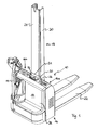
- Fig. 1 shows a pedestrian-controlled high-lift truck 10, in which the drive part 12 is guided via a drawbar 14.
- the driving part 12 has a battery room 16 which is divided into side battery rooms 16a and 16b.
- battery compartment is generally used for a space in the vehicle that can accommodate a battery for the vehicle, but other components of the vehicle such as a charger and / or control unit for the truck may also be provided.
- the mast 18 connects, from the in Fig. 1 the center mast 20 and two parallel forks 22 can be seen.
- the center mast 20 is arranged centrally with respect to the width of the drive member 12 and consists of a plurality of rails, with which a load carriage with two forks 22 is movably connected.
- the center mast has on its rear side facing the drive part a mast covering 24, which extends over the entire free height of the center mast 20.
- the mast covering 24 opens on the drive side on a battery compartment lining 26.
- the battery compartment lining 26 extends over the entire width of the battery compartment 16 and partially covers the battery compartment also on the fork side.
- On the battery compartment lining 26, the drive side is followed by a further panel 28, which covers the drive part on the drive side.
- the battery compartment trim 26 has an integrally formed therewith tab 30 which forms a transition from the battery compartment trim to the mast panel 24.
- the approach 30 has an opening through which an emergency stop lever 32 protrudes from the vehicle interior and is clearly visible and accessible to an operator.
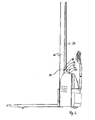
- Fig. 2 shows the truck from a view from the side. It can be clearly seen that the mast fairing 24 tapers towards the top of the center mast. In her pointing to the drive part end, the mast panel 24 connects to the extension 30 of the battery compartment cover. Mast fairing 24 and shoulder 30 adjoin the back of the mast along the edge 31 (cf. Fig. 1 ) to each other, in which case a defined gap between the two parts of the panel may be provided.
- the connection region between the mast covering 24 and the projection 30 consists laterally of a connecting edge, the two parallel, horizontally extending edge portions 33 and 34 have. Both edge portions, which are spaced apart in the longitudinal direction of the mast 20, are interconnected by a central portion 38. The middle section 38 of the connecting edge is inclined towards the mast 20.
- the design of the terminal edge ensures that the mast fairing 24, which is not yet connected to the center mast 20, is assembled and disassembled by the orientation of the center section 38 on the lug and the course of the corresponding mating terminal edges on the mast fairing independently of the battery compartment fairing can.
- the mast panel 24 covers only the back of the center mast and does not extend over the side wall portions of the center mast. Basically, it is also possible to form the center mast with an integral fairing.
- the battery compartment lining 26 also extends laterally on the drive part in the region of an edge 40.
- the remaining trim parts on the vehicle body and the mast in Fig. 2 dark, while the battery compartment trim and other lining parts for the battery compartment, the mast and the drive part are shown bright.
- the region of the edge 40 forms a rounded edge without sharp corners.
Landscapes
- Engineering & Computer Science (AREA)
- Transportation (AREA)
- Structural Engineering (AREA)
- Civil Engineering (AREA)
- Life Sciences & Earth Sciences (AREA)
- Geology (AREA)
- Mechanical Engineering (AREA)
- Chemical & Material Sciences (AREA)
- Combustion & Propulsion (AREA)
- Forklifts And Lifting Vehicles (AREA)
- Body Structure For Vehicles (AREA)
- Arrangement Or Mounting Of Propulsion Units For Vehicles (AREA)
Abstract
Description
- Die vorliegende Erfindung betrifft ein Flurförderzeug mit einem Antriebsteil und einem mit diesem verbundenen Hubgerüst. Das Antriebsteil weist mindestens einen Batterieraum auf, der eine oder mehrere Batterien aufnehmen kann. Das Hubgerüst ist mit einem Mittelmast ausgestattet, dessen zum Antriebsteil gewandte Rückseite teilweise an den Batterieraum angrenzt.
- Der Batterieraum und die Rückseite des Mittelmastes sind verkleidet, wobei der Batterieraum und die Rückseite des Mittelmastes mindestens teilweise bedeckt sind. Hier können für die Verkleidung drei Verkleidungsteile vorgesehen werden, von denen ein erstes Verkleidungsteil die Rückseite des Mittelmastes teilweise und die zwei anderen Verkleidungsteile jeweils seitlich des Mittelmastes angeordnet sind und den Batterieraum in einem vorgesehenen Bereich abdecken. Als nachteilig bei einer solchen mehrteiligen Verkleidung hat sich herausgestellt, dass drei Verkleidungsteile vorgesehen sein müssen, die einen zusätzlichen Montageaufwand darstellen und zudem zusätzliche Herstellungskosten sowie Logistikkosten für die Produktion bedeuten. Ferner ist auch die Montage durch auftretende Toleranzen und Einstellarbeiten der Verkleidungsteile relativ zueinander erschwert.
- Der Erfindung liegt die Aufgabe zugrunde, ein Flurförderzeug mit einer Verkleidung bereitzustellen, bei dem in besonders einfacher Weise der Batterieraum und die Rückseite eines Mittelmastes teilweise verkleidet werden können.
- Erfindungsgemäß wird die Aufgabe durch ein Flurförderzeug mit den Merkmalen aus Anspruch 1 gelöst. Vorteilhafte Ausgestaltungen bilden den Gegenstand der Unteransprüche.
- Das erfindungsgemäße Flurförderzeug besitzt ein Antriebsteil, das mindestens einen Batterieraum aufweist sowie ein Hubgerüst, das einen Mittelmast besitzt. Die zum Antriebsteil gewandte Rückseite des Mittelmastes grenzt teilweise an den Batterieraum an, wobei der Batterieraum und mindestens ein Teil der Rückseite des Mittelmastes eine Verkleidung tragen. Die erfindungsgemäße Verkleidung bildet eine Batterieraumverkleidung an der Oberseite des Batterieraums, die diesen mindestens teilweise bedeckt. Erfindungsgemäß besitzt die Verkleidung für den Batterieraum einen Ansatz, der teilweise die Rückseite des Mittelmastes mit abdeckt. Bei der erfindungsgemäßen Ausgestaltung der Verkleidung ist ein Verkleidungsteil für den Batterieraum ausreichend, um den Batterieraum teilweise und einen unteren Abschnitt auf der Antriebsseite des Mittelmastes abzudecken. Die erfindungsgemäße Batterieraumverkleidung kann den Batterieraum auch seitlich des Mittelmastes abdecken. In dem Bereich, in dem die Batterieraumverkleidung auf den Mast stößt, ist an dieser ein Ansatz ausgebildet, der nicht nur den Batterieraum sondern auch einen unteren Teil des Mittelmastes abdeckt. Hierdurch ist es möglich, die Batterieraumverkleidung, die ohne diesen Ansatz zweiteilig ausgebildet wäre oder deren Teile allenfalls über einen dünnen instabilen Steg miteinander verbunden werden könnten, einteilig als stabiles Verkleidungsteil auszubilden. Indem die Batterieraumverkleidung auch teilweise den Mittelmast an dessen Rückseite abdeckt, steht für die Batterieraumverkleidung ausreichend Material zur Verfügung, um so eine in sich formstabile und damit für die Montage gut handhabbare Batterieraumverkleidung zu schaffen. Weiterhin kann aufgrund der stabilen Ausgestaltung der erfindungsgemäßen Verkleidung auch die Anzahl der Befestigungspunkte an dem Antriebsteil reduziert werden.
- In einer bevorzugten Ausgestaltung bedeckt eine Mastverkleidung die Rückseite des Mittelmastes oberhalb des Ansatzes der Batterieraumverkleidung. In einer bevorzugten Ausgestaltung der Batterieraumverkleidung besitzt deren Ansatz einen Querschnitt, der in seinen Abmessungen mit dem Querschnitt der Mastverkleidung für den Mittelmast übereinstimmt. Die Mastverkleidung des Mittelmastes setzt dabei oberhalb des Ansatzes an und stellt sicher, dass eine an dem Fahrzeugkörper arbeitende Bedienperson nicht direkt in Kontakt mit dem Mittelmast und den sich darin bewegenden Teilen gelangt. Indem der Ansatz der Batterieraumverkleidung das Profil der Mastverkleidung aufgreift, können sowohl Batterieraumverkleidung als auch Mastverkleidung in einem Anschlussbereich direkt ineinander übergehen, wobei hier ein definierter Spalt zwischen der Batterieraumverkleidung und der darüber liegenden Verkleidung für den Mast vorgesehen werden kann.
- In einer bevorzugten Ausgestaltung weist die Batterieraumverkleidung im Bereich des Ansatzes eine Öffnung auf, durch die ein Bedienelement aus der Verkleidung vorsteht. Bei dem Bedienelement kann es sich beispielsweise um einen zentral hinter dem Mittelmast angeordneten Not-Stopp-Hebel handeln. Auch ist es möglich, andere Bedienelemente, die bevorzugt in einer zentralen Lage an dem Flurförderzeug positioniert werden sollen, in der Ausnehmung an dem Ansatz vorzusehen.
- In einer zweckmäßigen Ausgestaltung deckt die Batterieraumverkleidung den Batterieraum auf seiner Oberseite mindestens teilweise ab.
- Ebenso kann die Batterieraumverkleidung den Batterieraum teilweise auf der zum Hubgerüst weisenden Seite abdecken. Zweckmäßigerweise besitzt die Batterieraumverkleidung einen seitlich umgebogenen Rand, der sich von der Oberseite bis zur Vorderseite des Batterieraums erstreckt.
- In einer besonders bevorzugten Ausgestaltung besitzt der Ansatz der Batterieraumverkleidung auf der Rückseite des Mastes eine quer zur Längsrichtung des Mittelmastes verlaufende rückseitige Anschlusskante und jeweils eine seitliche Anschlusskante, die in die rückseitige Anschlusskante mündet und eine Neigung aufweist, die einen spitzen Winkel mit der Längsrichtung des Mastes einschließt. Ein besonderer Vorteil der so ausgebildeten Anschlusskanten der Batterieraumverkleidung ist, dass die oberhalb der Batterieraumverkleidung angebrachte Mastverkleidung, insbesondere über die Neigung der seitlichen Anschlusskanten, unabhängig von der Batterieraumverkleidung montiert und demontiert werden kann.
- In einer besonders bevorzugten Ausgestaltung besitzt die seitliche Anschlusskante drei Abschnitte, von denen ein erster und dritter Abschnitt quer zur Längsrichtung des Mastes verlaufen und ein mittlerer zweiter Abschnitt, geneigt zwischen dem ersten und dem dritten Abschnitt verläuft, wobei die Neigung zu dem Mast hinweist. Die Orientierung der Anschlusskante stellt sicher, dass die oberhalb der Batterieraumverkleidung montierte Mastverkleidung bei der Demontage von dem Mast fort nach schräg oben entfernt werden kann. Zudem können Batterieraum- und Mastverkleidung unabhängig voneinander und in beliebiger Reihenfolge montiert und demontiert werden.
- Eine bevorzugte Ausgestaltung der Erfindung wird nachfolgend anhand von Figuren näher erläutert.
- Es zeigt:
- Fig. 1
- ein deichsel geführtes Hochhubfahrzeug mit Mittelmast in einer perspektivischen Ansicht von der Antriebsseite,
- Fig. 1a
- die Batterieraumverkleidung in einer leicht angehobenen Position in einer perspektivischen Ansicht von der Gabelseite,
- Fig. 2
- das Fahrzeug aus
Fig.1 in einer Ansicht von der Seite, - Fig. 3
- das Fahrzeug aus
Fig. 1 in einer Ansicht von oben und - Fig. 4
- eine Schnittansicht durch den Mittelmast im Bereich der Mastverkleidung.
-
Fig. 1 zeigt ein deichselgeführtes Hochhubfahrzeug 10, bei dem das Antriebsteil 12 über eine Deichsel 14 geführt wird. Das Antriebsteil 12 besitzt einen Batterieraum 16, der sich in seitliche Batterieräume 16a und 16b unterteilt. In der Fachsprache wird der Begriff "Batterieraum" allgemein für einen Raum im Fahrzeug verwendet, der eine Batterie für das Fahrzeug aufnehmen kann, in dem aber auch andere Komponenten des Fahrzeugs, wie beispielsweise Ladegerät und/oder Steuereinheit für das Flurförderzeug, vorgesehen sein können. An das Antriebsteil 12 schließt sich das Hubgerüst 18 an, von dem inFig. 1 der Mittelmast 20 und zwei parallele Gabelzinken 22 zu erkennen sind. Der Mittelmast 20 ist mittig im Hinblick auf die Breite des Antriebsteils 12 angeordnet und besteht aus mehreren Profilschienen, mit denen ein Lastschlitten mit zwei Gabelzinken 22 verfahrbar verbunden ist. - Der Mittelmast besitzt auf seiner zum Antriebsteil gewandten Rückseite eine Mastverkleidung 24, die sich über die gesamte freie Höhe des Mittelmastes 20 erstreckt. Die Mastverkleidung 24 mündet antriebsseitig auf einer Batterieraumverkleidung 26. Die Batterieraumverkleidung 26 erstreckt sich über die gesamte Breite des Batterieraums 16 und bedeckt den Batterieraum teilweise auch gabelseitig. An die Batterieraumverkleidung 26 schließt sich antriebsseitig eine weitere Verkleidung 28 an, die das Antriebsteil antriebsseitig bedeckt. Die Batterieraumverkleidung 26 besitzt einen einstückig mit dieser ausgebildeten Ansatz 30, der einen Übergang von der Batterieraumverkleidung zu der Mastverkleidung 24 bildet. Der Ansatz 30 besitzt eine Öffnung, durch die ein Not-Stopp-Hebel 32 aus dem Fahrzeuginneren vorsteht und für eine Bedienperson gut sichtbar und zugänglich ist.
-
Fig. 1a zeigt die Batterieraumverkleidung 26 in einer perspektivischen Ansicht von der Gabelseite. In dem angehobenen Zustand sind die beiden Batterieräume 16a und 16b zu erkennen. Ferner ist zu erkennen, dass der Ansatz 30 und die gabelseitige Abdeckung des Batterieraums eine Aussparung bilden, die den Mittelmast des Hubgerüsts teilweise aufnimmt. -
Fig. 2 zeigt das Flurförderzeug aus einer Ansicht von der Seite. Deutlich zu erkennen ist, dass die Mastverkleidung 24 zur Spitze des Mittelmastes hin sich verjüngt. In ihrem zum Antriebsteil weisenden Ende schließt die Mastverkleidung 24 an den Ansatz 30 der Batterieraumverkleidung an. Mastverkleidung 24 und Ansatz 30 grenzen an der Rückseite des Mastes entlang der Kante 31 (vergleicheFig. 1 ) aneinander, wobei hier ein definierter Spalt zwischen beiden Teilen der Verkleidung vorgesehen sein kann. Der Anschlussbereich zwischen der Mastverkleidung 24 und dem Ansatz 30 besteht seitlich aus einer Anschlusskante, die zwei parallele, horizontal zueinander verlaufende Kantenabschnitte 33 und 34 aufweisen. Beide Kantenabschnitte, die in Längsrichtung des Mastes 20 voneinander beabstandet sind, werden durch einen Mittelabschnitt 38 miteinander verbunden. Der Mittelabschnitt 38 der Anschlusskante ist dabei zum Mast 20 hin geneigt. Durch die Ausgestaltung der Anschlusskante wird sichergestellt, dass die Mastverkleidung 24, die noch nicht mit dem Mittelmast 20 verbunden ist, durch die Orientierung des Mittelabschnitts 38 an dem Ansatz und den Verlauf der entsprechenden zugehörigen Anschlusskanten an der Mastverkleidung unabhängig von der Batterieraumverkleidung montiert und demontiert werden kann. - Wie in
Fig. 4 dargestellt bedeckt die Mastverkleidung 24 nur die Rückseite des Mittelmastes und erstreckt sich nicht über die seitlichen Wandabschnitte des Mittelmastes. Grundsätzlich ist es auch möglich, den Mittelmast mit einer integralen Verkleidung auszubilden. - In
Fig. 2 ist ferner zu erkennen, dass die Batterieraumverkleidung 26 sich im Bereich einer Kante 40 auch seitlich an dem Antriebsteil erstreckt. Zur besseren Übersicht sind die übrigen Verkleidungsteile an dem Fahrzeugkörper sowie der Mast inFig. 2 dunkel dargestellt, während die Batterieraumverkleidung sowie weitere Verkleidungsteile für den Batterieraum, den Mast und das Antriebsteil hell dargestellt sind. Der Bereich der Kante 40 bildet dabei eine abgerundete Kante ohne scharfe Ecken. -
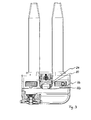
Fig. 3 zeigt das Flurförderzeug ausFig. 1 in einer Ansicht von oben. Es ist zu erkennen, dass die Batterieraumverkleidung die obere Seite des Batterieraums teilweise verdeckt. Ferner ist der Ansatz 30 zu erkennen, aus dem der Not-Stopp-Hebel 32 hervorsteht. Aus der gewählten Perspektive ist von der Mastverkleidung 24 in der Draufsicht lediglich der durch Verbreiterung der Mastverkleidung sichtbare untere Teil zu erkennen.
Claims (9)
- Flurförderzeug mit einem Antriebsteil (12), das mindestens einen Batterieraum (16a, 16b) aufweist, und mit einem Hubgerüst (18), das einen Mittelmast (20) aufweist, dessen zum Antriebsteil gewandte Rückseite teilweise an den Batterieraum grenzt, wobei der Batterieraum verkleidet ist,
dadurch gekennzeichnet, dass- die Verkleidung eine Batterieraumverkleidung (26) aufweist, die eine Oberseite des Batterieraums (16a, 16b) mindestens teilweise bedeckt und einen Ansatz (30) besitzt, der teilweise die Rückseite des Mittelmastes (20) mit abdeckt. - Flurförderzeug nach Anspruch 1, dadurch gekennzeichnet, dass der Mast eine Verkleidung oberhalb des Ansatzes der Batterieraumverkleidung aufweist.
- Flurförderzeug nach Anspruch 2, dadurch gekennzeichnet, dass der Ansatz (30) der Batterieraumverkleidung (26) einen Querschnitt aufweist, der im Querschnitt mit der Mastverkleidung übereinstimmt.
- Flurförderzeug nach einem der Ansprüche 1 bis 3, dadurch gekennzeichnet, dass die Batterieverkleidung im Bereich des Ansatzes eine Öffnung aufweist, durch die ein Bedienelement (32) für das Flurförderzeug aus der Verkleidung vorsteht.
- Flurförderzeug nach einem der Ansprüche 1 bis 4, dadurch gekennzeichnet, dass die Batterieraumverkleidung den Batterieraum auf seiner Antriebsseite teilweise bedeckt.
- Flurförderzeug nach einem der Ansprüche 1 bis 5, dadurch gekennzeichnet, dass die Batterieraumverkleidung teilweise den Batterieraum auf der Gabelseite bedeckt.
- Flurförderzeug nach Anspruch 5 und 6, dadurch gekennzeichnet, dass die Batterieraumverkleidung einen seitlich umgebogenen Rand (40) aufweist, der sich von der Oberseite bis zur Vorderseite erstreckt.
- Flurförderzeug nach einem der Ansprüche 1 bis 7, dadurch gekennzeichnet, dass der Anschluss zwischen Ansatz (30) der Batterieraumverkleidung (26) auf der Rückseite des Mastes eine quer zur Längsrichtung des Mastes verlaufende Anschlusskante (31) besitzt und seitlich jeweils eine Anschlusskante (33, 34, 38) aufweist, die in die rückseitige Anschlusskante (31) mündet und einen Kantenabschnitt (38) aufweist, der einen spitzen Winkel mit der Längsrichtung des Mastes einschließt.
- Flurförderzeug nach Anspruch 8, dadurch gekennzeichnet, dass die seitliche Anschlusskante drei Abschnitte (33, 34, 38) aufweist, von denen ein erster Abschnitt (33) und ein zweiter Abschnitt (34) quer zur Längsrichtung des Mastes (20) verlaufen und ein mittlerer Abschnitt (38) geneigt zwischen dem ersten und dem dritten Abschnitt (33, 34) verläuft und der mittlere Abschnitt zu dem Mast geneigt ist.
Applications Claiming Priority (1)
| Application Number | Priority Date | Filing Date | Title |
|---|---|---|---|
| DE200920006960 DE202009006960U1 (de) | 2009-05-11 | 2009-05-11 | Flurförderzeug mit Verkleidung |
Publications (2)
| Publication Number | Publication Date |
|---|---|
| EP2251300A1 true EP2251300A1 (de) | 2010-11-17 |
| EP2251300B1 EP2251300B1 (de) | 2012-12-19 |
Family
ID=40984485
Family Applications (1)
| Application Number | Title | Priority Date | Filing Date |
|---|---|---|---|
| EP20100004624 Active EP2251300B1 (de) | 2009-05-11 | 2010-05-03 | Flurförderzeug mit Verkleidung |
Country Status (2)
| Country | Link |
|---|---|
| EP (1) | EP2251300B1 (de) |
| DE (1) | DE202009006960U1 (de) |
Cited By (1)
| Publication number | Priority date | Publication date | Assignee | Title |
|---|---|---|---|---|
| WO2023065345A1 (en) * | 2021-10-22 | 2023-04-27 | Crown Equipment Corporation | Industrial truck |
Families Citing this family (2)
| Publication number | Priority date | Publication date | Assignee | Title |
|---|---|---|---|---|
| DE102008060712A1 (de) * | 2008-06-26 | 2009-12-31 | Om Carrelli Elevatori S.P.A. | Flurförderzeug |
| DE102009043182A1 (de) * | 2009-09-26 | 2011-03-31 | Jungheinrich Ag | Flurförderzeug mit einem Fahrzeugrahmen und mindestens einem Verkleidungsteil |
Citations (3)
| Publication number | Priority date | Publication date | Assignee | Title |
|---|---|---|---|---|
| DE19505457A1 (de) * | 1995-02-17 | 1996-08-22 | Linde Ag | Batteriebetriebenes Flurförderzeug |
| DE29514676U1 (de) * | 1995-09-13 | 1997-01-30 | Jungheinrich AG., 22047 Hamburg | Stapler |
| US6199665B1 (en) * | 1997-11-11 | 2001-03-13 | Crown Equipment Corporation | Straddle arm for fork lift truck |
-
2009
- 2009-05-11 DE DE200920006960 patent/DE202009006960U1/de not_active Expired - Lifetime
-
2010
- 2010-05-03 EP EP20100004624 patent/EP2251300B1/de active Active
Patent Citations (3)
| Publication number | Priority date | Publication date | Assignee | Title |
|---|---|---|---|---|
| DE19505457A1 (de) * | 1995-02-17 | 1996-08-22 | Linde Ag | Batteriebetriebenes Flurförderzeug |
| DE29514676U1 (de) * | 1995-09-13 | 1997-01-30 | Jungheinrich AG., 22047 Hamburg | Stapler |
| US6199665B1 (en) * | 1997-11-11 | 2001-03-13 | Crown Equipment Corporation | Straddle arm for fork lift truck |
Cited By (3)
| Publication number | Priority date | Publication date | Assignee | Title |
|---|---|---|---|---|
| WO2023065345A1 (en) * | 2021-10-22 | 2023-04-27 | Crown Equipment Corporation | Industrial truck |
| US12258062B2 (en) | 2021-10-22 | 2025-03-25 | Crown Equipment Corporation | Industrial truck |
| AU2021470385B2 (en) * | 2021-10-22 | 2025-08-14 | Crown Equipment Corporation | Industrial truck |
Also Published As
| Publication number | Publication date |
|---|---|
| EP2251300B1 (de) | 2012-12-19 |
| DE202009006960U1 (de) | 2009-08-20 |
Similar Documents
| Publication | Publication Date | Title |
|---|---|---|
| DE102016120850B4 (de) | Batteriegehäuse | |
| DE102014224400B4 (de) | Aufbaurahmen für Fahrzeug | |
| DE112015000063B4 (de) | Fahrzeugkarosserie mit Öffnung in einem Fahrzeugkarosserie-Heckabschnitt | |
| DE112015003102B4 (de) | Starrer Containerboden sowie Container mit demselben | |
| EP1534578A1 (de) | Karosserie mit einer tragstruktur aus zusammengesetzten teilmodulen | |
| DE2636365C2 (de) | Unterbau für eine Kraftfahrzeugkarosserie | |
| DE102012207506A1 (de) | Struktur für das Heckende eines Fahrzeugoberteils | |
| DE19937220C1 (de) | Fahrzeugdach mit verstellbarem Verschlußelement | |
| DE102020202884A1 (de) | Unterbaustruktur für ein Fahrzeug | |
| EP2251300B1 (de) | Flurförderzeug mit Verkleidung | |
| EP3362335B1 (de) | Verkleidung eines aussenschwellers, energiespeicherelement und fahrzeug | |
| DD157153A5 (de) | Seitengriff fuer geschirre | |
| DE102013016456A1 (de) | Unterbau für ein Kraftfahrzeug | |
| DE10036979A1 (de) | Einstückig geformte Radaufblendenabdeckung und Trittbrett für Nutzfahrzeuge | |
| EP1036728B1 (de) | Längsgesickter Träger, insbesondere Dachträger für ein Kraftfahrzeug | |
| EP2952418B1 (de) | Bausatz für nutzfahrzeug-fahrerhäuser ungleicher abmessungen | |
| DE102018104978A1 (de) | Struktur des Heckbereichs der Fahrzeugkarosserie | |
| EP2251297B1 (de) | Flurförderzeug mit mindestens zwei Verkleidungsteilen | |
| DE3608535C1 (en) | Electrical terminal block having a name-plate support | |
| EP1055587A2 (de) | Mehrteilige Stirnwand für eine Kraftfahrzeugrohbaukarosserie | |
| DE202014100584U1 (de) | Frontblende für Möbel | |
| EP3710314B1 (de) | Verkleidungssystem, verfahren zur herstellung einer verkleideten kraftfahrzeugkarosserie und kraftfahrzeug | |
| EP2351893A2 (de) | Aufsatzsockel, insbesondere für Dachöffnungen, z.B. für Rauch- und Wärmeabzugsanlagen | |
| EP1362762B1 (de) | Flurförderzeug | |
| DE10113616C1 (de) | Laderaumabdeckung für Kraftwagen, wie für Kombinations-Personenkraftwagen od. dgl. |
Legal Events
| Date | Code | Title | Description |
|---|---|---|---|
| PUAI | Public reference made under article 153(3) epc to a published international application that has entered the european phase |
Free format text: ORIGINAL CODE: 0009012 |
|
| 17P | Request for examination filed |
Effective date: 20100923 |
|
| AK | Designated contracting states |
Kind code of ref document: A1 Designated state(s): AL AT BE BG CH CY CZ DE DK EE ES FI FR GB GR HR HU IE IS IT LI LT LU LV MC MK MT NL NO PL PT RO SE SI SK SM TR |
|
| AX | Request for extension of the european patent |
Extension state: BA ME RS |
|
| GRAP | Despatch of communication of intention to grant a patent |
Free format text: ORIGINAL CODE: EPIDOSNIGR1 |
|
| RIC1 | Information provided on ipc code assigned before grant |
Ipc: B66F 9/24 20060101AFI20120822BHEP Ipc: B66F 9/075 20060101ALI20120822BHEP Ipc: B66F 9/08 20060101ALI20120822BHEP |
|
| GRAS | Grant fee paid |
Free format text: ORIGINAL CODE: EPIDOSNIGR3 |
|
| GRAA | (expected) grant |
Free format text: ORIGINAL CODE: 0009210 |
|
| AK | Designated contracting states |
Kind code of ref document: B1 Designated state(s): AL AT BE BG CH CY CZ DE DK EE ES FI FR GB GR HR HU IE IS IT LI LT LU LV MC MK MT NL NO PL PT RO SE SI SK SM TR |
|
| REG | Reference to a national code |
Ref country code: GB Ref legal event code: FG4D Free format text: NOT ENGLISH |
|
| REG | Reference to a national code |
Ref country code: CH Ref legal event code: EP |
|
| REG | Reference to a national code |
Ref country code: AT Ref legal event code: REF Ref document number: 589308 Country of ref document: AT Kind code of ref document: T Effective date: 20130115 |
|
| REG | Reference to a national code |
Ref country code: DE Ref legal event code: R096 Ref document number: 502010001879 Country of ref document: DE Effective date: 20130228 |
|
| PG25 | Lapsed in a contracting state [announced via postgrant information from national office to epo] |
Ref country code: NO Free format text: LAPSE BECAUSE OF FAILURE TO SUBMIT A TRANSLATION OF THE DESCRIPTION OR TO PAY THE FEE WITHIN THE PRESCRIBED TIME-LIMIT Effective date: 20130319 Ref country code: HR Free format text: LAPSE BECAUSE OF FAILURE TO SUBMIT A TRANSLATION OF THE DESCRIPTION OR TO PAY THE FEE WITHIN THE PRESCRIBED TIME-LIMIT Effective date: 20121219 Ref country code: LT Free format text: LAPSE BECAUSE OF FAILURE TO SUBMIT A TRANSLATION OF THE DESCRIPTION OR TO PAY THE FEE WITHIN THE PRESCRIBED TIME-LIMIT Effective date: 20121219 Ref country code: FI Free format text: LAPSE BECAUSE OF FAILURE TO SUBMIT A TRANSLATION OF THE DESCRIPTION OR TO PAY THE FEE WITHIN THE PRESCRIBED TIME-LIMIT Effective date: 20121219 Ref country code: ES Free format text: LAPSE BECAUSE OF FAILURE TO SUBMIT A TRANSLATION OF THE DESCRIPTION OR TO PAY THE FEE WITHIN THE PRESCRIBED TIME-LIMIT Effective date: 20130330 Ref country code: SE Free format text: LAPSE BECAUSE OF FAILURE TO SUBMIT A TRANSLATION OF THE DESCRIPTION OR TO PAY THE FEE WITHIN THE PRESCRIBED TIME-LIMIT Effective date: 20121219 |
|
| REG | Reference to a national code |
Ref country code: NL Ref legal event code: VDEP Effective date: 20121219 |
|
| REG | Reference to a national code |
Ref country code: LT Ref legal event code: MG4D |
|
| PG25 | Lapsed in a contracting state [announced via postgrant information from national office to epo] |
Ref country code: GR Free format text: LAPSE BECAUSE OF FAILURE TO SUBMIT A TRANSLATION OF THE DESCRIPTION OR TO PAY THE FEE WITHIN THE PRESCRIBED TIME-LIMIT Effective date: 20130320 Ref country code: LV Free format text: LAPSE BECAUSE OF FAILURE TO SUBMIT A TRANSLATION OF THE DESCRIPTION OR TO PAY THE FEE WITHIN THE PRESCRIBED TIME-LIMIT Effective date: 20121219 Ref country code: SI Free format text: LAPSE BECAUSE OF FAILURE TO SUBMIT A TRANSLATION OF THE DESCRIPTION OR TO PAY THE FEE WITHIN THE PRESCRIBED TIME-LIMIT Effective date: 20121219 |
|
| PG25 | Lapsed in a contracting state [announced via postgrant information from national office to epo] |
Ref country code: EE Free format text: LAPSE BECAUSE OF FAILURE TO SUBMIT A TRANSLATION OF THE DESCRIPTION OR TO PAY THE FEE WITHIN THE PRESCRIBED TIME-LIMIT Effective date: 20121219 Ref country code: SK Free format text: LAPSE BECAUSE OF FAILURE TO SUBMIT A TRANSLATION OF THE DESCRIPTION OR TO PAY THE FEE WITHIN THE PRESCRIBED TIME-LIMIT Effective date: 20121219 Ref country code: CZ Free format text: LAPSE BECAUSE OF FAILURE TO SUBMIT A TRANSLATION OF THE DESCRIPTION OR TO PAY THE FEE WITHIN THE PRESCRIBED TIME-LIMIT Effective date: 20121219 Ref country code: BG Free format text: LAPSE BECAUSE OF FAILURE TO SUBMIT A TRANSLATION OF THE DESCRIPTION OR TO PAY THE FEE WITHIN THE PRESCRIBED TIME-LIMIT Effective date: 20130319 Ref country code: IS Free format text: LAPSE BECAUSE OF FAILURE TO SUBMIT A TRANSLATION OF THE DESCRIPTION OR TO PAY THE FEE WITHIN THE PRESCRIBED TIME-LIMIT Effective date: 20130419 |
|
| PG25 | Lapsed in a contracting state [announced via postgrant information from national office to epo] |
Ref country code: PT Free format text: LAPSE BECAUSE OF FAILURE TO SUBMIT A TRANSLATION OF THE DESCRIPTION OR TO PAY THE FEE WITHIN THE PRESCRIBED TIME-LIMIT Effective date: 20130419 Ref country code: NL Free format text: LAPSE BECAUSE OF FAILURE TO SUBMIT A TRANSLATION OF THE DESCRIPTION OR TO PAY THE FEE WITHIN THE PRESCRIBED TIME-LIMIT Effective date: 20121219 Ref country code: RO Free format text: LAPSE BECAUSE OF FAILURE TO SUBMIT A TRANSLATION OF THE DESCRIPTION OR TO PAY THE FEE WITHIN THE PRESCRIBED TIME-LIMIT Effective date: 20121219 Ref country code: PL Free format text: LAPSE BECAUSE OF FAILURE TO SUBMIT A TRANSLATION OF THE DESCRIPTION OR TO PAY THE FEE WITHIN THE PRESCRIBED TIME-LIMIT Effective date: 20121219 |
|
| PLBE | No opposition filed within time limit |
Free format text: ORIGINAL CODE: 0009261 |
|
| STAA | Information on the status of an ep patent application or granted ep patent |
Free format text: STATUS: NO OPPOSITION FILED WITHIN TIME LIMIT |
|
| PG25 | Lapsed in a contracting state [announced via postgrant information from national office to epo] |
Ref country code: DK Free format text: LAPSE BECAUSE OF FAILURE TO SUBMIT A TRANSLATION OF THE DESCRIPTION OR TO PAY THE FEE WITHIN THE PRESCRIBED TIME-LIMIT Effective date: 20121219 |
|
| 26N | No opposition filed |
Effective date: 20130920 |
|
| PG25 | Lapsed in a contracting state [announced via postgrant information from national office to epo] |
Ref country code: CY Free format text: LAPSE BECAUSE OF FAILURE TO SUBMIT A TRANSLATION OF THE DESCRIPTION OR TO PAY THE FEE WITHIN THE PRESCRIBED TIME-LIMIT Effective date: 20121219 |
|
| BERE | Be: lapsed |
Owner name: JUNGHEINRICH A.G. Effective date: 20130531 |
|
| PG25 | Lapsed in a contracting state [announced via postgrant information from national office to epo] |
Ref country code: MC Free format text: LAPSE BECAUSE OF FAILURE TO SUBMIT A TRANSLATION OF THE DESCRIPTION OR TO PAY THE FEE WITHIN THE PRESCRIBED TIME-LIMIT Effective date: 20121219 Ref country code: IT Free format text: LAPSE BECAUSE OF FAILURE TO SUBMIT A TRANSLATION OF THE DESCRIPTION OR TO PAY THE FEE WITHIN THE PRESCRIBED TIME-LIMIT Effective date: 20121219 |
|
| REG | Reference to a national code |
Ref country code: DE Ref legal event code: R097 Ref document number: 502010001879 Country of ref document: DE Effective date: 20130920 |
|
| REG | Reference to a national code |
Ref country code: IE Ref legal event code: MM4A |
|
| PG25 | Lapsed in a contracting state [announced via postgrant information from national office to epo] |
Ref country code: BE Free format text: LAPSE BECAUSE OF NON-PAYMENT OF DUE FEES Effective date: 20130531 |
|
| PG25 | Lapsed in a contracting state [announced via postgrant information from national office to epo] |
Ref country code: IE Free format text: LAPSE BECAUSE OF NON-PAYMENT OF DUE FEES Effective date: 20130503 |
|
| REG | Reference to a national code |
Ref country code: CH Ref legal event code: PL |
|
| PG25 | Lapsed in a contracting state [announced via postgrant information from national office to epo] |
Ref country code: CH Free format text: LAPSE BECAUSE OF NON-PAYMENT OF DUE FEES Effective date: 20140531 Ref country code: LI Free format text: LAPSE BECAUSE OF NON-PAYMENT OF DUE FEES Effective date: 20140531 |
|
| PG25 | Lapsed in a contracting state [announced via postgrant information from national office to epo] |
Ref country code: MT Free format text: LAPSE BECAUSE OF FAILURE TO SUBMIT A TRANSLATION OF THE DESCRIPTION OR TO PAY THE FEE WITHIN THE PRESCRIBED TIME-LIMIT Effective date: 20121219 |
|
| PG25 | Lapsed in a contracting state [announced via postgrant information from national office to epo] |
Ref country code: SM Free format text: LAPSE BECAUSE OF FAILURE TO SUBMIT A TRANSLATION OF THE DESCRIPTION OR TO PAY THE FEE WITHIN THE PRESCRIBED TIME-LIMIT Effective date: 20121219 |
|
| PG25 | Lapsed in a contracting state [announced via postgrant information from national office to epo] |
Ref country code: TR Free format text: LAPSE BECAUSE OF FAILURE TO SUBMIT A TRANSLATION OF THE DESCRIPTION OR TO PAY THE FEE WITHIN THE PRESCRIBED TIME-LIMIT Effective date: 20121219 |
|
| PG25 | Lapsed in a contracting state [announced via postgrant information from national office to epo] |
Ref country code: LU Free format text: LAPSE BECAUSE OF NON-PAYMENT OF DUE FEES Effective date: 20130503 Ref country code: HU Free format text: LAPSE BECAUSE OF FAILURE TO SUBMIT A TRANSLATION OF THE DESCRIPTION OR TO PAY THE FEE WITHIN THE PRESCRIBED TIME-LIMIT; INVALID AB INITIO Effective date: 20100503 Ref country code: MK Free format text: LAPSE BECAUSE OF FAILURE TO SUBMIT A TRANSLATION OF THE DESCRIPTION OR TO PAY THE FEE WITHIN THE PRESCRIBED TIME-LIMIT Effective date: 20121219 |
|
| REG | Reference to a national code |
Ref country code: FR Ref legal event code: PLFP Year of fee payment: 7 |
|
| REG | Reference to a national code |
Ref country code: AT Ref legal event code: MM01 Ref document number: 589308 Country of ref document: AT Kind code of ref document: T Effective date: 20150503 |
|
| PG25 | Lapsed in a contracting state [announced via postgrant information from national office to epo] |
Ref country code: AT Free format text: LAPSE BECAUSE OF NON-PAYMENT OF DUE FEES Effective date: 20150503 |
|
| REG | Reference to a national code |
Ref country code: FR Ref legal event code: PLFP Year of fee payment: 8 |
|
| REG | Reference to a national code |
Ref country code: FR Ref legal event code: PLFP Year of fee payment: 9 |
|
| PG25 | Lapsed in a contracting state [announced via postgrant information from national office to epo] |
Ref country code: AL Free format text: LAPSE BECAUSE OF FAILURE TO SUBMIT A TRANSLATION OF THE DESCRIPTION OR TO PAY THE FEE WITHIN THE PRESCRIBED TIME-LIMIT Effective date: 20121219 |
|
| PGFP | Annual fee paid to national office [announced via postgrant information from national office to epo] |
Ref country code: DE Payment date: 20250519 Year of fee payment: 16 |
|
| PGFP | Annual fee paid to national office [announced via postgrant information from national office to epo] |
Ref country code: GB Payment date: 20250522 Year of fee payment: 16 |
|
| PGFP | Annual fee paid to national office [announced via postgrant information from national office to epo] |
Ref country code: FR Payment date: 20250523 Year of fee payment: 16 |