EP2250864B1 - Trennbarer isolierter doppelschnittstellenverbinder mit umgossenem faradayschem käfig - Google Patents
Trennbarer isolierter doppelschnittstellenverbinder mit umgossenem faradayschem käfig Download PDFInfo
- Publication number
- EP2250864B1 EP2250864B1 EP09723948.7A EP09723948A EP2250864B1 EP 2250864 B1 EP2250864 B1 EP 2250864B1 EP 09723948 A EP09723948 A EP 09723948A EP 2250864 B1 EP2250864 B1 EP 2250864B1
- Authority
- EP
- European Patent Office
- Prior art keywords
- faraday cage
- separable insulated
- bus bar
- shell
- insulated connector
- Prior art date
- Legal status (The legal status is an assumption and is not a legal conclusion. Google has not performed a legal analysis and makes no representation as to the accuracy of the status listed.)
- Active
Links
Images


Classifications
-
- H—ELECTRICITY
- H01—ELECTRIC ELEMENTS
- H01R—ELECTRICALLY-CONDUCTIVE CONNECTIONS; STRUCTURAL ASSOCIATIONS OF A PLURALITY OF MUTUALLY-INSULATED ELECTRICAL CONNECTING ELEMENTS; COUPLING DEVICES; CURRENT COLLECTORS
- H01R13/00—Details of coupling devices of the kinds covered by groups H01R12/70 or H01R24/00 - H01R33/00
- H01R13/46—Bases; Cases
- H01R13/53—Bases or cases for heavy duty; Bases or cases for high voltage with means for preventing corona or arcing
-
- H—ELECTRICITY
- H02—GENERATION; CONVERSION OR DISTRIBUTION OF ELECTRIC POWER
- H02G—INSTALLATION OF ELECTRIC CABLES OR LINES, OR OF COMBINED OPTICAL AND ELECTRIC CABLES OR LINES
- H02G15/00—Cable fittings
- H02G15/02—Cable terminations
- H02G15/06—Cable terminating boxes, frames or other structures
-
- H—ELECTRICITY
- H01—ELECTRIC ELEMENTS
- H01H—ELECTRIC SWITCHES; RELAYS; SELECTORS; EMERGENCY PROTECTIVE DEVICES
- H01H85/00—Protective devices in which the current flows through a part of fusible material and this current is interrupted by displacement of the fusible material when this current becomes excessive
- H01H85/02—Details
- H01H2085/0225—Means for preventing discharge, e.g. corona ring
-
- H—ELECTRICITY
- H01—ELECTRIC ELEMENTS
- H01H—ELECTRIC SWITCHES; RELAYS; SELECTORS; EMERGENCY PROTECTIVE DEVICES
- H01H9/00—Details of switching devices, not covered by groups H01H1/00 - H01H7/00
- H01H9/02—Bases, casings, or covers
- H01H9/0207—Adjustable mounting of casings
-
- Y—GENERAL TAGGING OF NEW TECHNOLOGICAL DEVELOPMENTS; GENERAL TAGGING OF CROSS-SECTIONAL TECHNOLOGIES SPANNING OVER SEVERAL SECTIONS OF THE IPC; TECHNICAL SUBJECTS COVERED BY FORMER USPC CROSS-REFERENCE ART COLLECTIONS [XRACs] AND DIGESTS
- Y10—TECHNICAL SUBJECTS COVERED BY FORMER USPC
- Y10S—TECHNICAL SUBJECTS COVERED BY FORMER USPC CROSS-REFERENCE ART COLLECTIONS [XRACs] AND DIGESTS
- Y10S439/00—Electrical connectors
- Y10S439/921—Transformer bushing type or high voltage underground connector
Definitions
- the invention relates generally to separable insulated connector systems for electric power systems. More specifically, the invention relates to a separable insulated connector having a molded faraday cage.
- Separable insulated connectors provide an electric connection between components of an electric power system. More specifically, separable insulated connectors often connect sources of energy - such as cables carrying electricity generated by a power plant - to energy distribution systems or components thereof, such as switchgears and transformers. Other types of separable insulated connectors can connect to other separable insulated connectors on one or both of their ends.
- the connector can include a variety of different interfaces.
- many separable insulated connectors include two interfaces, one at each end of the connector.
- Some separable insulated connectors can include one male interface and one female interface, two male interfaces, or two female interfaces.
- An exemplary connector with two female interfaces can, for example, include a bus bar -- or conductive member that carries current -- connecting the two female interfaces.
- Each female interface can include a "cup" through which one end of a probe can be inserted and then connected to the bus bar disposed within the separable insulated connector. The other end of the probe then can be connected to energy distribution components or other separable insulated connectors.
- the cups are typically made from semi-conductive material and thus can serve as a faraday cage.
- a "semi-conductive" material can refer to rubber or any other type of material that carries current, and thus can include conductive materials.
- the purpose of a faraday cage is to shield all gaps of air within the mating components of the separable insulated connector, as these air gaps can cause corona discharge within the connector. This discharge can occur if there is a voltage drop across the air gaps, and the discharge can corrode the rubber materials often used to make the separable insulated connector.
- the faraday cage ensures that the various mating components have the same electric potential, and thus prevents corona discharge within the mating components.
- the cups of such female-female separable insulated connectors are made from a rigid, conductive metal, such as copper.
- the cups, as well as the bus bar connecting them, are placed within a semi-conductive shell of the separable insulated connector.
- Conventional separable insulated connectors also can include various layers of insulating material -- such as between the cups and the probes inserted therein, between the cups and the shell, and around the bus bar.
- the various layers of insulating material used in conventional separable insulated connectors can provide a barrier to shield the high voltage components from the exposed shell. Such a configuration can reduce or remove the risk of electric shock from touching the exterior of the separable insulated connectors.
- insulating material which is generally made from a rubber such as ethylene propylene dienemonomer (EPDM) rubber, thermoplastic rubbers (TPRs), and/or silicone rubber -- to the cups or the bus bar, both of which are generally made from metal. Rubber does not typically form a strong bond with metal. A strong bond between the insulating material and the metal cups and/or bus bar also is desirable because without a strong bond, air gaps can form between the metal and insulating materials. Corona or partial discharge can occur within the air gaps between the conductive metal and the semi-conductive rubber. The discharge can lead to severe damage of the insulating material and the connector.
- EPDM ethylene propylene dienemonomer
- TPRs thermoplastic rubbers
- silicone rubber both of which are generally made from metal. Rubber does not typically form a strong bond with metal.
- a strong bond between the insulating material and the metal cups and/or bus bar also is desirable because without a strong bond, air gaps can form between the metal and insulating materials. Corona or partial discharge can occur within the air
- a need in the art exists for a separable insulated connector in an electric power system that addresses the disadvantages found in the prior art. Specifically, a need in the art exists for a dual interface separable insulated connector that does not require insulating material to bond to the bus bar. A need in the art also exists for a dual interface separable insulated connector with a faraday cage that can bond to insulating material without the use of an adhesive material, if desired. Yet another need in the art exists for a dual interface separable insulated connector with a faraday cage - and a method of manufacturing the same - where the connection between the faraday cage and bus bar is stronger and less likely to disconnect.
- US 4029380 discloses a separable insulated connector according to the preamble of claim 1.
- the invention is defined by the features of claim 1.
- the faraday cage can be molded over the bus bar, thereby avoiding many of the problems and difficulties associated with the prior art. Molding the semi-conductive faraday cage over the bus bar can eliminate the need for insulating material to bond to the metal bus bar. Instead, the semi-conductive material of the faraday cage can surround the bus bar, and then insulating material can bond to the semi-conductive material.
- the bus bar need not be smoothed or finished to remove burrs, other irregularities, or sharp corners.
- the rubber faraday cage can have the same or similar electric potential as the bus bar, and thus any burrs present on the bar may not cause stress or damage to the rubber faraday cage.
- the surface of the rubber faraday cage can be smoothed much more easily than the metal bus bar before insulating material will be applied to the faraday cage.
- the insulating material can contact a smooth, semi-conductive surface (i.e., the faraday cage) without the manufacturer having to engage in the lengthy and costly procedure of smoothing the metal bus bar.
- Another advantage associated with eliminating the need for an insulating material to bond to the bus bar is the reduction or removal of the need to apply an adhesive agent to the bus bar.
- the rubber insulating material can bond to the rubber faraday cage much more easily than with the metal bus bar. For example, if the insulating material is applied to the faraday cage in a liquid state, bonding of the insulating material to the faraday cage can occur upon curing of the insulating material. Thus, a strong, tight bond (i.e., without air gaps) can be formed between the rubber faraday cage and the rubber insulating material without the use of a costly and potentially toxic adhesive agent. Although air gaps may exist between the bus bar and the faraday cage due to the comparatively poor bonding ability of rubber to metal, these air gaps do not pose a problem to the separable insulated connector because the faraday cage and bus bar have the same electric potential.
- the invention provides a dual interface separable insulated connector that includes a semi-conductive outer shell with a faraday cage disposed therein, the faraday cage having two interfaces.
- the faraday cageincluding each of the two interfaces -- can be made from a semi-conductive rubber material, such as EPDM, TPR, or silicone mixed with a conductive material such as carbon black.
- the shell of the separable insulated connector can be made from the same material as the faraday cage.
- the shell also can be made from a semi-conductive rubber material, such as EPDM, TPR, or silicone mixed with a conductive material such as carbon black.
- the separable insulated connector also can include an insulating layer, as described previously, between the faraday cage and the shell.
- the use of a semi-conductive material to form the interfaces or "cups" can eliminate the need to use an adhesive agent in bonding insulating material to the faraday cage interfaces. Because the faraday cage -- including the interfaces -- can be made from a rubber material rather than a metal such as copper, the insulating material can bond to the interfaces much more easily, as described previously with respect to the bus bar.
- the use of a semi-conductive material to form the faraday cage interfaces allows the faraday cage to maintain the ability -- associated with conventional faraday cages -- to prevent corona discharge.
- the interfaces of the dual interface separable insulated connector can be configured such that a probe can be inserted into each of the interfaces.
- the dual interface separable insulated connector can provide an electric connection between the two probes inserted therein.
- the separable insulated connector can provide an electric connection between the two energy distribution components upon connection of the two probes to a first energy distribution component and second energy distribution component, respectively.
- the invention provides a method of manufacturing a dual interface separable insulated connector that includes a semi-conductive outer shell with a faraday cage disposed therein.
- a manufacturer can inject a semi-conductive rubber material into a mold or press to form the semi-conductive shell. The shell then can be cured and/or hardened.
- the manufacturer can take a conductive member or bus bar and put it into a mold or press in the shape of the dual interface faraday cage.
- Two steel mandrels also can be inserted into the mold to provide the holes or openings that will form the two interfaces of the faraday cage.
- the manufacturer then can inject a semi-conductive rubber material into the mold to form the faraday cage.
- the faraday cage -- with the bus bar being disposed therein -- then can be cured and/or hardened.
- the faraday cage then can be inserted into the shell.
- the shell may need to be cut or split, manufactured to include such a cut or split therein, or formed into two separate pieces during the molding process.
- the shell can be made (or remade) into one piece.
- insulating material can be injected into the shell, thereby providing a layer of insulating material between the faraday cage and the shell. The insulating material then can be cured and/or hardened, thereby securing the faraday cage within the shell.
- FIG. 1 is a cross-sectional side view of a dual interface separable insulated connector 100 comprising a faraday cage 102 molded over a bus bar 106, according to an exemplary embodiment.
- the dual interface connector 100 includes a shell 104, a faraday cage 102 disposed therein, and a bus bar 106 disposed within the faraday cage 102.
- the dual interface connector 100 includes a first opening 112A and second opening 112B, and probes 110A, 110B is inserted into each of the first and second openings 112A, 112B, respectively.
- the faraday cage 1 includes a first cup 108A and a second cup 108B, corresponding with the shell's 104 first and second openings 112A, 112B, respectively.
- the first and second probes 110A, 110B can be inserted through the first and second openings 112A, 112B and through the first and second cups 108A, 108B, and then attached to the bus bar 106, thereby providing a connection from the first probe 110A to the second probe 110B.
- the dual interface connector 100 also can include a layer 114 of insulating material between the faraday cage 102 and the shell 104. As shown in Figure 1 , in exemplary embodiments, both the shell 104 and the faraday cage 102 disposed therein can have a substantially "U" shape.
- the shell 104 of the dual interface connector 100 can be made from a variety of materials.
- the shell 104 can be made from semi-conductive rubber.
- suitable rubbers include ethylene propylene dienemonomer (EPDM) rubber, thermoplastic rubbers (TPRs), and silicone rubber. Any of these rubbers then can be mixed with a conductive material, such as carbon black or other suitable material, thereby providing the semi-conductive property for the shell 104.
- the faraday cage 102 of the dual interface connector 100 can be made from a variety of materials.
- the faraday cage 102 can be made from the same material used to make the shell 104.
- the faraday cage 102 can be made from semi-conductive rubber, such as a mixture of a conductive material and EPDM rubber, TPRs, or silicone rubber.
- the layer 114 of insulating material between the shell 104 and the faraday cage 102 also can be made from a variety of materials.
- the insulating material can be made from any suitable non-conductive material, known to those having ordinary skill in the art and having the benefit of the present disclosure.
- the insulating material can be made from EPDM rubber, TPRs, or silicone rubber, but without being mixed with a significant amount of conductive material, thereby retaining an insulating property.
- the dual interface connector 100 also can include other insulating layers.
- the faraday cage 102 can include an additional insulating layer 116A, 116B on the first and second cups 108A, 108B inside the faraday cage 102.
- these cup insulating layers 116A, 116B can be made from the same material used in the insulating layer 114 between the shell 104 and faraday cage 102.
- the cup insulating layers 116A, 116B can be made from a different insulating material. Particular exemplary types of insulating materials that can be used to form the cup insulating layers 116A, 116B are disclosed in U.S. Patent No.
- cup insulating layers 116A, 116B can be relatively thin when compared to the insulating layer 114 between the shell 104 and faraday cage 102.
- the shell 104 of the dual interface connector 100 also can include additional insulating layers.
- the shell 104 can include two insulating sleeves 118A, 118B, each one located near the first and second openings 112A, 112B of the shell 104.
- the insulating sleeves 118A, 118B can be made from the same material used in the insulating layer 114 between the shell 104 and faraday cage 102, or alternatively, from a different suitable material.
- the additional insulating layers such as the cup insulating layers 116A, 116B and the insulating sleeves 118A, 118B can provide additional insulation for the dual interface connector 100.
- the cup insulating layers 116A, 116B can provide load-break switching for the dual interface connector 100. Additionally, the cup insulating layers 116A, 116B can protect against partial vacuum flashover which could cause the connector 100 to be pulled off of a bushing connected thereto.
- the insulating sleeves 118A, 118B can prevent a switching failure made when separating a probe 110A, 110B from the connector 100. Absent the insulating sleeves 118A, 118B, a probe 110A, 110B may contact the semi-conductive shell 104, thereby causing a switching failure.
- the shell 104 of the dual interface connector 100 also can comprise a variety of additional components.
- the shell 104 of the dual interface connector 100 also can include a pulling eye 122.
- the pulling eye 122 can function as a handle for the dual interface connector 100.
- the pulling eye 122 can be pulled or pushed to install the dual interface connector 100 on an energy distribution component, to adjust the position of the dual interface connector 100, or to disconnect the dual interface connector 100 from an energy distribution component.
- the pulling eye 122 can be made from the same material used to make the shell 104, such as EPDM rubber or another type of rubber.
- the pulling eye 122 can include a steel insert 122b, disposed within the rubber, providing strength and resilience to the pulling eye 122.
- the shell 104 of the dual interface connector 100 also can include an injection port 120, through which insulating material can be injected.
- the shell 104 can include one or more ground wire tabs 124 to which a wire can be attached and grounded. Because the shell 104 can be made from semi-conductive rubber, the ground wire can provide ground shield continuity for the dual interface connector 100, thereby providing deadfront safety for the shell 104. In other words, the grounded shell 104 can allow operators to touch the exterior of the dual interface connector 100 safely, thereby removing or reducing the risk of accidental electric shock.
- the first and second probes 110A, 110B can be made from a variety of conductive materials, such as conductive metals known to those having ordinary skill in the art and having the benefit of the present disclosure.
- the probes 110A, 110B can be made from conductive copper.
- the probes 110A, 110B can include a threaded end 126A, 126B for connection to the bus bar 106.
- the bus bar 106 can be made from a variety of conductive materials, such as conductive copper or other metals. Regardless of the particular material used, the bus bar 106 can include two holes 106A, 106B, into which the first and second probes 110A, 110B can be inserted and affixed. In a particular exemplary embodiment, the threaded ends 126A, 126B of the probes 110A, 110B can be screwed into corresponding threads in the holes 106a, 106b of the bus bar 106.
- the conductive property of the bus bar 106 can carry load current, and thus can provide an electric connection between the first and second probes 110A, 110B.
- the faraday cage 102 can be molded over the bus bar 106, such that entire bus bar 106 is disposed within the faraday cage 102. Because the bus bar 106 can be overmolded with the faraday cage 102, the bus bar 106 need not be polished, refined, or smoothed to remove any burrs on the bus bar 106. Instead, in an exemplary embodiment, the rubber faraday cage 102 can be molded into a smooth, curved shape, which can take less effort than removing burrs from a metal bus bar 106.
- the faraday cage 102 can be made from a semi-conductive material, it can have the same or similar electric potential as the bus bar 106. Therefore, any air gaps that may be present between the faraday cage 102 and the bus bar 106 may not cause corona discharge.
- the insulating layer 114 can border the faraday cage 102.
- the bond between the faraday cage 102 and the insulating layer 114 can be tighter than the bond between the faraday cage 102 and the bus bar 106.
- there may few air gaps, if any, between the faraday cage 102 and the insulating layer 114 which can reduce or eliminate the possibility of corona discharge between two layers 102, 114 having a different electric potential.
- such a tight bond can be formed relatively easily because both the faraday cage 102 and the insulating layer 114 can be primarily made of rubber materials that bond to each other easily.
- the first and second cups 108A, 108B of the faraday cage 102 can contact the insulating layer 114 on the outer side of the cups 108A, 108B.
- the first and second cups 108A, 108B of the faraday cage 102 also can bond easily with the insulating material because the cups and the insulating material can be made from rubber.
- the inner side of the cups 108A, 108B can contact the cup insulating layers 116A, 116B, as described previously.
- an empty space 128A, 128B can exist in the area inside the cup insulating layers 116A, 116B.
- These empty spaces 128A, 128B can be configured such that bushings capable of interfacing with the probes 110A, 110B can be inserted and secured therein.
- such bushings can be part of - or can be connected to - another separable insulated connector or an energy distribution component.
- the faraday cage 102 comprises the cups 108A, 108B and the portions that extend around the bus bar 106.
- FIG. 2 is a diagram illustrating an electric power system 200 utilizing a dual interface separable insulated connector 100 that comprises a faraday cage 102 molded over a bus bar 106, according to an exemplary embodiment.
- one end 126A of a first probe 110A can be inserted into the first opening 112A of the dual interface separable insulated connector 100, the first cup 108A, and the first hole 106A of the bus bar 106, and the other end 226A of the first probe 110A can be inserted into a bushing 230 that connects to another separable insulated connector such as a T-body connector 232.
- one end 126B of a second probe 110B can be inserted into the second opening 112B of the dual interface separable insulated connector 100, the second cup 108B, and the second hole 106B of the bus bar 106, and the other end 226B of the second probe 110B can be inserted into an energy distribution component 234.
- the dual interface separable insulated connector 100 can provide an electric connection between the T-body connector 232 and the energy distribution component 234.
- the dual interface separable insulated connector 100 can connect to the other separable insulated connector without first connecting to a bushing 230 as shown in Figure 2 .
- the dual interface separable insulated connector 100 can connect two separable insulated connectors together, rather than connecting to an energy distribution component 234.
- the dual interface separable insulated connector 100 can connect to a variety of other separable insulated connectors and/or energy distribution components 234 using a variety of configurations, known to those having ordinary skill in the art and having the benefit of the present disclosure.
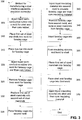
- FIG 3 is a flow diagram illustrating a method 300 for manufacturing a dual interface separable insulated connector 100 comprising a faraday cage 102 molded over a bus bar 106 according to an exemplary embodiment. The method 300 will be described with reference to Figures 1 and 3 .
- liquid semi-conductive rubber is injected into a mold for the shell 104 and then cured until the rubber has cured or solidified.
- the size, shape, dimension, and configuration of the mold can be selected based upon the desired size, shape, dimension, and configuration of the shell 104 of the dual interface separable insulated connector 100.
- the mold can be shaped to include one or more ground wire tabs 124 and/or a pulling eye 122. Additionally, if the mold is shaped to include a pulling eye 122 on the shell 104, a metal insert can be placed in the mold, approximately the size and shape of the pulling eye 122, such that the insert can be disposed within the pulling eye 122. As described previously, the insert can provide additional strength for the pulling eye 122.
- a first set of steel mandrels is placed into a mold for the faraday cage 102.
- two steel mandrels can be placed into the mold for the faraday cage 102, and can have a size corresponding with the first and second cups 108A, 108B.
- the width of the first set of steel mandrels can be wider than the desired width for the first and second cups 108A, 108B, to account for the cup insulating layers 116A, 116B that may be formed.
- the first set of steel mandrels can be inserted into the holes 106A, 106B of the bus bar 106.
- the first set of steel mandrels can be screwed into the threads in the holes 106A, 106B of the bus bar 106.
- the dimensions of the mold can be selected based upon the desired dimensions of the faraday cage 102.
- the bus bar 106 is placed into the mold for the faraday cage 102 of the dual interface separable insulated connector 100.
- the bus bar 106 can be coated with an adhesive agent.
- an adhesive agent may not be necessary, as the bond between the bus bar 106 and the faraday cage 102 can include air gaps as described previously, an adhesive agent may be utilized if a stronger bond is desired. Such a bond may be desired to prevent any warping or tearing of the faraday cage 102, insulating material, or shell 104 upon adjusting of the dual interface separable insulated connector 100, such as by pulling on the pulling eye 122.
- first and second holes 106A, 106B can be created in the bus bar 106, such that first and second probes 110A, 110B can be inserted and attached therein.
- the holes 106A, 106B can be threaded so as to correspond with threaded ends 126A, 126B of the first and second probes 110A, 110B.
- liquid semi-conductive rubber is injected into the mold for the faraday cage 102.
- the semi-conductive rubber then can be cured until it has cured and hardened.
- step 325 the faraday cage 102 is removed from the mold for the faraday cage 102.
- the first set of steel mandrels is replaced with a second set of steel mandrels.
- the second set of steel mandrels are narrower than the first set.
- the second set of steel mandrels can have a width substantially equal to the desired width of the first and second cups 108A, 108B.
- the second set of steel mandrels can be inserted into the holes 106A, 106B of the bus bar 106.
- the second set of steel mandrels can be screwed into the threads in the holes 106A, 106B of the bus bar 106.
- a second set of steel mandrels might not be used, and instead, the hole created by the removal of the first set of steel mandrels may be left open for the remainder of the manufacturing process.
- the faraday cage 102 will not include cup insulating layers 116A, 116B, then a second set of steel mandrels may not need to be inserted into the faraday cage 102 after removal of the first set of steel mandrels.
- the faraday cage 102 is placed into a second mold.
- the second mold for the faraday cage 102 can be larger in dimension than the first mold, and can be configured to form the cup insulating layers 116A, 116B of the faraday cage 102 upon the injection of insulating material into the second mold.
- liquid insulating material is injected into the second mold to insulate the faraday cage 102 and then cured to form the cup insulating layers 116A, 116B.
- a variety of rubber materials - such as EPDM rubber, TPRs, or silicone rubber - can be used to form the cup insulating layers 116A, 116B.
- the insulating material then can be cured until it has cured and hardened.
- step 345 the faraday cage 102 is removed from the second mold, and the second set of steel mandrels is removed from the faraday cage 102.
- the faraday cage 102 is inserted into the shell 104.
- the shell 104 can be cut or split -- or alternatively, the shell 104 could have been formed in step 305 to include a cut or split therein -- to provide additional flexibility such that the faraday cage 102 can be inserted therein.
- the shell 104 when formed in step 305, can be formed in two separate pieces, thereby providing additional flexibility and a larger opening into which the faraday cage 102 can be inserted. After the faraday cage 102 has been inserted into the shell 104, the splits or pieces of the shell 104 can be attached (or reattached) together, thereby enclosing the faraday cage 102 within the shell 104.
- the insulating sleeves 118A, 118B are formed and bonded to the shell 104 of the dual interface separable insulated connector 100.
- the insulating sleeves 118A, 118B can be formed by injecting suitable insulating material into a mold for the insulating sleeves 118A, 118B.
- the insulating sleeves 118A, 118B then can be bonded to the shell 104 of the dual interface separable insulated connector 100 by using an adhesive.
- the insulating sleeves 118A, 118B can be attached to the shell 104 before the insulating sleeves 118A, 118B has completely cured, and thus it can bond to the shell 104 upon curing of the insulating sleeves 118A, 118B.
- a third set of steel mandrels is inserted into the faraday cage 102.
- This third set replaces the second set of steel mandrels removed in step 345.
- the third set of steel mandrels can be more narrow than the second set.
- the hole created by the removal of the steel mandrels may be left open for the remainder of the manufacturing process.
- the faraday cage 102 can be inserted into the shell 104 with the third set of steel mandrels inserted therein.
- the third set of steel mandrels can be inserted into the faraday cage 102 at different stages of the manufacturing process.
- the third set of steel mandrels can be inserted into the faraday cage 102 during or after steps 345, 350, or 355, or at any other time during the manufacturing process.
- step 365 the shell 104 and faraday cage 102 are placed into a third mold.
- the third mold can be configured to form the insulating layer 114 upon injection of insulating material into the third mold.
- insulating material is injected into the shell 104 and then cured.
- the insulating material injected in step 345 can form the insulating layer 114 between the shell 104 and faraday cage 102.
- the insulating material can be injected through the injection port 120.
- the injection port 120 can be opened before injection and closed thereafter.
- a variety of rubber materials - such as EPDM rubber, TPRs, or silicone rubber - can be used to form the insulating layer 114.
- the insulating material then can be cured until it has cured and hardened.
- the third set of steel mandrels (if present) in the faraday cage 102 can be removed from the faraday cage 102.
- the first and second probes 110A, 110B can be inserted into the first and second holes in the bus bar 106 after the third set of steel mandrels has been removed from the faraday cage 102.
- the dual interface separable insulated connector 100 can have substantially the same form as the exemplary dual interface separable insulated connector 100 shown in Figure 1 .
Landscapes
- Cable Accessories (AREA)
- Connector Housings Or Holding Contact Members (AREA)
- Measuring Instrument Details And Bridges, And Automatic Balancing Devices (AREA)
Claims (14)
- Trennbarer isolierter Verbinder (100), umfassend:eine Schale (104);einen in der Schale angeordneten Faradayschen Käfig (102); undeine zur Gänze im Faradayschen Käfig angeordnete leitfähige Sammelschiene (106),wobei die Schale eine erste Öffnung (112A) und eine zweite Öffnung (112B) aufweist,wobei die Sammelschiene ein erstes Loch (106A) und ein zweites Loch (106B) aufweist,wobei der Faradayschen Käfig ein halbleitendes Kautschukgehäuse aufweist, dadurch gekennzeichnet, dassdas halbleitende Kautschukgehäuse einen ersten von der leitfähigen Sammelschiene in Richtung der ersten Öffnung verlaufenden Napf (108A) und einen zweiten von der leitfähigen Sammelschiene in Richtung der zweiten Öffnung verlaufenden Napf (108B) aufweist,wobei eine erste Napfisolierschicht (116A) innerhalb des ersten Napfes (108A) des Gehäuses und eine zweite Napfisolierschicht (116B) innerhalb des zweiten Napfes (108B) des Gehäuses angeordnet ist,wobei die erste Öffnung mit dem ersten Napf und dem ersten Loch fluchtet, undwobei die zweite Öffnung mit dem zweiten Napf und dem zweiten Loch fluchtet.
- Trennbarer isolierter Verbinder (100) nach Anspruch 1, wobei die leitfähige Sammelschiene (106) mit dem halbleitenden Kautschukgehäuse in Kontakt ist.
- Trennbarer isolierter Verbinder (100) nach Anspruch 1, wobei die Schale (104) halbleitenden Kautschuk aufweist.
- Trennbarer isolierter Verbinder (100) nach Anspruch 1, wobei die Schale (104) eine Misching aus Ethylen-Propylen-Dienmonomer-Kautschuk und einem leitfähigen Material aufweist.
- Trennbarer isolierter Verbinder (100) nach Anspruch 1, weiter umfassend eine Isolierschicht (114) zwischen der Schale (104) und dem Faradayschen Käfig (102).
- Trennbarer isolierter Verbinder (100) nach Anspruch 5, wobei die Isolierschicht (114) Kautschuk aufweist.
- Trennbarer isolierter Verbinder (100) nach Anspruch 5, wobei die Isolierschicht (114) Ethylen-Propylen-Dienmonomer-Kautschuk aufweist.
- Trennbarer isolierter Verbinder (100) nach Anspruch 1, wobei der trannbare isolierte Verbinder weiter umfasst:eine erste in das erste Loch (106A) der Sammelschiene eingeführte Sonde (110A); undeine zweite in das zweite Loch (106B) der Sammelschiene eingeführte Sonde (110B),wobei zwischen der ersten und der zweiten Sonde eine elektrische Verbindung besteht.
- Trennbarer isolierter Verbinder (100) nach Anspruch 8, wobei die Sammelschiene 106) die elektrische Verbindung zwischen der ersten Sonde (110A) und der zweiten Sonde (110B) herstellt.
- Trennbarer isolierter Verbinder (100) nach Anspruch 1, weiter umfassend:eine erste Isoliermuffe (118A); undeine zweite Isoliermuffe (118B),wobei die erste Isoliermuffe rund um die erste Öffnung der Schale angeordnet ist, undwobei die zweite Isoliermuffe rund um die zweite Öffnung der Schale angeordnet ist.
- Trennbarer isolierter Verbinder (100) nach Anspruch 10, wobei die erste Isoliermuffe (118A) Kautschuk aufweist, und
wobei die zweite Isoliermuffe (118B) Kautschuk aufweist. - Trennbarer isolierter Verbinder (100) nach Anspruch 10, wobei die erste Isoliermuffe (118A) Ethylen-Propylen-Dienmonomer-Kautschuk aufweist, und
wobei die zweite Isoliermuffe (118B) Ethylen-Propylen-Dienmonomer-Kautschuk aufweist. - Trennbarer isolierter Verbinder (100) nach Anspruch 1, weiter umfassend eine an den Verbinder gekoppelte Fädelöse (122).
- Trennbarer isolierter Verbinder (100) nach Anspruch 1, wobei die leitfähige Sammelschiene (106) mit dem halbleitenden Kautschukgehäuse in Kontakt ist.
Applications Claiming Priority (2)
| Application Number | Priority Date | Filing Date | Title |
|---|---|---|---|
| US12/072,164 US7578682B1 (en) | 2008-02-25 | 2008-02-25 | Dual interface separable insulated connector with overmolded faraday cage |
| PCT/US2009/034204 WO2009120425A1 (en) | 2008-02-25 | 2009-02-16 | Dual interface separable insulated connector with overmolded faraday cage |
Publications (3)
| Publication Number | Publication Date |
|---|---|
| EP2250864A1 EP2250864A1 (de) | 2010-11-17 |
| EP2250864A4 EP2250864A4 (de) | 2012-02-15 |
| EP2250864B1 true EP2250864B1 (de) | 2016-07-13 |
Family
ID=40973364
Family Applications (1)
| Application Number | Title | Priority Date | Filing Date |
|---|---|---|---|
| EP09723948.7A Active EP2250864B1 (de) | 2008-02-25 | 2009-02-16 | Trennbarer isolierter doppelschnittstellenverbinder mit umgossenem faradayschem käfig |
Country Status (10)
| Country | Link |
|---|---|
| US (2) | US7578682B1 (de) |
| EP (1) | EP2250864B1 (de) |
| CN (1) | CN102017828B (de) |
| AU (1) | AU2009229119A1 (de) |
| BR (1) | BRPI0908858B1 (de) |
| CA (1) | CA2715848C (de) |
| ES (1) | ES2592186T3 (de) |
| MX (1) | MX2010009120A (de) |
| TW (1) | TWI493809B (de) |
| WO (1) | WO2009120425A1 (de) |
Families Citing this family (16)
| Publication number | Priority date | Publication date | Assignee | Title |
|---|---|---|---|---|
| US7854620B2 (en) | 2007-02-20 | 2010-12-21 | Cooper Technologies Company | Shield housing for a separable connector |
| US7666012B2 (en) | 2007-03-20 | 2010-02-23 | Cooper Technologies Company | Separable loadbreak connector for making or breaking an energized connection in a power distribution network |
| US7661979B2 (en) | 2007-06-01 | 2010-02-16 | Cooper Technologies Company | Jacket sleeve with grippable tabs for a cable connector |
| US8056226B2 (en) * | 2008-02-25 | 2011-11-15 | Cooper Technologies Company | Method of manufacturing a dual interface separable insulated connector with overmolded faraday cage |
| US7905735B2 (en) | 2008-02-25 | 2011-03-15 | Cooper Technologies Company | Push-then-pull operation of a separable connector system |
| US7950940B2 (en) | 2008-02-25 | 2011-05-31 | Cooper Technologies Company | Separable connector with reduced surface contact |
| US8109776B2 (en) * | 2008-02-27 | 2012-02-07 | Cooper Technologies Company | Two-material separable insulated connector |
| FR2950486B1 (fr) * | 2009-09-23 | 2012-08-31 | Eurocopter France | Obturateur de connecteurs electriques |
| US8066526B2 (en) * | 2010-03-16 | 2011-11-29 | Spx Corporation | Jumper connector |
| US8262405B1 (en) * | 2011-03-15 | 2012-09-11 | Avx Corporation | Wire-to-wire connector |
| US9350103B2 (en) | 2012-07-19 | 2016-05-24 | Thomas & Betts International, Llc | Electrical connector having grounding mechanism |
| US9385493B2 (en) * | 2014-04-10 | 2016-07-05 | S&C Electric Company | Adjustable bus bar for power distribution equipment |
| EP3229034B1 (de) * | 2016-04-08 | 2023-04-26 | TE Connectivity Solutions GmbH | Prüfstand mit faraday-käfig |
| CN110945724B (zh) | 2017-06-08 | 2021-08-27 | 康普技术有限责任公司 | 用于单扭绞导体对的连接器 |
| CN107768593A (zh) * | 2017-10-12 | 2018-03-06 | 东莞市迈科新能源有限公司 | 一种除电池极片毛刺的装置及其除电池极片毛刺的方法 |
| US10741313B1 (en) | 2019-02-06 | 2020-08-11 | Eaton Intelligent Power Limited | Bus bar assembly with integrated surge arrestor |
Family Cites Families (236)
| Publication number | Priority date | Publication date | Assignee | Title |
|---|---|---|---|---|
| FR481359A (fr) | 1916-03-31 | 1916-11-28 | Henri De La Valette | Dispositif d'assemblage pour connexions électriques |
| US1903956A (en) | 1931-04-17 | 1933-04-18 | Reyrolle A & Co Ltd | High voltage electric switch gear |
| FR1123946A (fr) | 1954-05-11 | 1956-10-01 | Installation de distribution de courant électrique | |
| US3115329A (en) | 1959-10-14 | 1963-12-24 | Wilson G Wing | Valve |
| US3474386A (en) | 1964-02-10 | 1969-10-21 | Edwin A Link | Electrical connector |
| US3315132A (en) | 1964-10-09 | 1967-04-18 | Johnson & Phillips Australia P | Busbar power distribution systems |
| US3392363A (en) | 1965-06-10 | 1968-07-09 | Amp Inc | Housing member for electrical connector members |
| US3949343A (en) | 1967-08-15 | 1976-04-06 | Joslyn Mfg. And Supply Co. | Grounded surface distribution apparatus |
| US4029380A (en) | 1967-08-15 | 1977-06-14 | Joslyn Mfg. And Supply Co. | Grounded surface distribution apparatus |
| US3835439A (en) * | 1967-08-15 | 1974-09-10 | Joslyn Mfg & Supply Co | Grounded surface distribution apparatus |
| US3915534A (en) | 1967-08-15 | 1975-10-28 | Joslyn Mfg & Supply Co | Grounded surface distribution apparatus |
| NL147874B (nl) | 1967-10-10 | 1975-11-17 | Smit Nijmegen Electrotec | Transformator met een regelschakelaar. |
| US3471669A (en) | 1968-01-16 | 1969-10-07 | Chance Co Ab | Encapsulated switch assembly for underground electric distribution service |
| US3509516A (en) | 1968-02-01 | 1970-04-28 | Mc Graw Edison Co | High voltage connector and entrance bushing assembly |
| US3542986A (en) | 1968-02-23 | 1970-11-24 | Gen Electric | Quick-make,quick-break actuator for high voltage electrical contacts |
| US3509518A (en) | 1968-03-11 | 1970-04-28 | Mc Graw Edison Co | High voltage cable connectors |
| US3539972A (en) | 1968-05-21 | 1970-11-10 | Amerace Esna Corp | Electrical connector for high voltage electrical systems |
| US3513425A (en) | 1969-05-21 | 1970-05-19 | Gen Electric | Modular electrical conductor termination system |
| US3594685A (en) | 1969-07-14 | 1971-07-20 | Joslyn Mfg & Supply Co | Electrical coupler |
| US3576493A (en) | 1969-09-25 | 1971-04-27 | Gen Electric | Molded conductor housing with a molded capacitance tap and method of making same |
| US3654590A (en) | 1969-12-30 | 1972-04-04 | Ameraca Esna Corp | Electrical contact devices for high voltage electrical systems |
| US3663928A (en) | 1970-01-09 | 1972-05-16 | Westinghouse Electric Corp | Electrical bushing assembly |
| US3652975A (en) | 1970-01-09 | 1972-03-28 | Westinghouse Electric Corp | Electrical connector assembly |
| US3626354A (en) | 1970-03-04 | 1971-12-07 | Philip M Banner | Polarity-reversing adapter means |
| US3670287A (en) | 1970-08-17 | 1972-06-13 | Westinghouse Electric Corp | Electrical connector assembly |
| US3725846A (en) | 1970-10-30 | 1973-04-03 | Itt | Waterproof high voltage connection apparatus |
| US3720904A (en) | 1971-02-04 | 1973-03-13 | Amp Inc | Self-actuating loadbreak connector |
| US3678432A (en) | 1971-04-26 | 1972-07-18 | Gen Electric | Vented fuse module for underground power cable system |
| US3740511A (en) | 1971-05-06 | 1973-06-19 | J Westmoreland | Vacuum switch |
| US3860322A (en) | 1972-01-03 | 1975-01-14 | Rte Corp | Sealed electrical connector |
| DE2221395C3 (de) | 1972-05-02 | 1974-09-19 | Omron Tateisi Electronics Co., Kyoto (Japan) | Stoßempfindlicher elektrischer Schalter |
| US3798586A (en) | 1972-05-22 | 1974-03-19 | P Huska | Union for connecting electrical conductors |
| US4343356A (en) | 1972-10-06 | 1982-08-10 | Sonics International, Inc. | Method and apparatus for treating subsurface boreholes |
| US3845233A (en) | 1973-02-12 | 1974-10-29 | Dielectrics Int Ltd | Pressurized insulant of solid and fluid for a conductor |
| US3826860A (en) | 1973-03-08 | 1974-07-30 | Amp Inc | High voltage electrical connector |
| US3953099A (en) | 1973-12-10 | 1976-04-27 | Bunker Ramo Corporation | One-piece environmental removable contact connector |
| US3945699A (en) | 1974-09-27 | 1976-03-23 | Kearney-National Inc. | Electric connector apparatus and method |
| US3955874A (en) | 1974-10-29 | 1976-05-11 | General Electric Company | Shielded power cable separable connector module having a conductively coated insulating rod follower |
| JPS5851393B2 (ja) | 1975-04-30 | 1983-11-16 | 松下電工株式会社 | 回転コネクタ− |
| US3957332A (en) | 1975-05-02 | 1976-05-18 | Kearney-National, Inc. | Electric connector apparatus and method |
| US3960433A (en) | 1975-09-05 | 1976-06-01 | General Electric Company | Shielded power cable separable connector module having conducting contact rod with a beveled shoulder overlapped by insulating follower material |
| US4102608A (en) | 1975-12-24 | 1978-07-25 | Commonwealth Scientific And Industrial Research Organization | Reciprocatory piston and cylinder machines |
| US4107486A (en) | 1976-06-30 | 1978-08-15 | S & C Electric Company | Switch operating mechanisms for high voltage switches |
| US4088383A (en) | 1976-08-16 | 1978-05-09 | International Telephone And Telegraph Corporation | Fault-closable electrical connector |
| US4067636A (en) | 1976-08-20 | 1978-01-10 | General Electric Company | Electrical separable connector with stress-graded interface |
| US4161012A (en) | 1977-03-02 | 1979-07-10 | Joslyn Mfg. And Supply Co. | High voltage protection apparatus |
| NL168662C (nl) | 1977-04-19 | 1982-04-16 | Coq Bv | Railsysteem voor een elektrische schakelinrichting voor hoge spanningen. |
| US4103123A (en) | 1977-06-27 | 1978-07-25 | Northwestern Public Service Company | Grounding device |
| US4123131A (en) | 1977-08-05 | 1978-10-31 | General Motors Corporation | Vented electrical connector |
| US4113339A (en) | 1977-08-29 | 1978-09-12 | Westinghouse Electric Corp. | Load break bushing |
| US4154993A (en) | 1977-09-26 | 1979-05-15 | Mcgraw-Edison Company | Cable connected drawout switchgear |
| US4223179A (en) | 1978-01-05 | 1980-09-16 | Joslyn Mfg. And Supply Co. | Cable termination connector assembly |
| US4152643A (en) | 1978-04-10 | 1979-05-01 | E. O. Schweitzer Manufacturing Co., Inc. | Voltage indicating test point cap |
| US4203017A (en) | 1978-07-24 | 1980-05-13 | Integrated Electronics Corporation | Electric switch |
| US4456942A (en) * | 1978-08-02 | 1984-06-26 | Rte Corporation | Gapless elbow arrester |
| US4186985A (en) | 1978-08-29 | 1980-02-05 | Amerace Corporation | Electrical connector |
| US4210381A (en) | 1978-08-30 | 1980-07-01 | Amerace Corporation | Electrical connector contacts |
| US4260214A (en) | 1979-07-23 | 1981-04-07 | International Telephone And Telegraph Corporation | Fault-closable electrical connector |
| US4353611A (en) | 1980-03-06 | 1982-10-12 | Amerace Corporation | Bushing well stud construction |
| US4360967A (en) | 1980-12-31 | 1982-11-30 | Amerace Corporation | Assembly tool for electrical connectors |
| US4354721A (en) | 1980-12-31 | 1982-10-19 | Amerace Corporation | Attachment arrangement for high voltage electrical connector |
| DE3110609A1 (de) | 1981-03-18 | 1982-10-07 | Siemens Ag | Mechanisch-elektrische steckverbindung |
| EP0062494A3 (de) | 1981-04-02 | 1984-03-21 | Kuraray Co., Ltd. | Verfahren und Vorrichtung zum Trennen von gemischten flüssigen Bestandteilen |
| JPS628125Y2 (de) | 1981-06-01 | 1987-02-25 | ||
| FR2508729A1 (fr) | 1981-06-24 | 1982-12-31 | Lb Air | Connecteur pour cables electriques |
| JPS5837708U (ja) | 1981-09-02 | 1983-03-11 | 三菱電機株式会社 | パツケ−ジ変電所 |
| US4484169A (en) | 1981-11-05 | 1984-11-20 | Mitsubishi Denki Kabushiki Kaisha | Transformer apparatus with -superimposed insulated switch and transformer units |
| US4600260A (en) | 1981-12-28 | 1986-07-15 | Amerace Corporation | Electrical connector |
| US4463227A (en) | 1982-02-05 | 1984-07-31 | S&C Electric Company | Mounting for an article which permits movement thereof between inaccessible and accessible positions |
| US4508413A (en) | 1982-04-12 | 1985-04-02 | Allied Corporation | Connector |
| JPS602005A (ja) | 1983-06-15 | 1985-01-08 | 株式会社日立製作所 | ガス絶縁開閉装置 |
| US4568804A (en) | 1983-09-06 | 1986-02-04 | Joslyn Mfg. And Supply Co. | High voltage vacuum type circuit interrupter |
| US4678253A (en) | 1984-10-29 | 1987-07-07 | Eaton Corporation | Bus duct having improved bus bar clamping structure |
| US4626755A (en) | 1984-12-14 | 1986-12-02 | General Electric Company | Sump pump motor switch circuit |
| GB8432608D0 (en) | 1984-12-22 | 1985-02-06 | Bp Chem Int Ltd | Strippable laminate |
| CN86100367B (zh) | 1985-05-09 | 1988-10-05 | 三菱电机株式会社 | 隔离开关 |
| DE3521365C1 (en) | 1985-06-14 | 1987-02-19 | Stocko Metallwarenfab Henkels | Electrical plug connection |
| CH671118A5 (de) | 1985-11-14 | 1989-07-31 | Bbc Brown Boveri & Cie | |
| US4822291A (en) | 1986-03-20 | 1989-04-18 | Joslyn Corporation | Gas operated electrical connector |
| JPH0622941Y2 (ja) | 1986-06-09 | 1994-06-15 | 関東自動車工業株式会社 | コネクタ |
| US4700258A (en) | 1986-07-21 | 1987-10-13 | Colt Industries Inc. | Lightning arrester system for underground loop distribution circuit |
| US4820183A (en) | 1986-09-12 | 1989-04-11 | Cooper Industries | Connection mechanism for connecting a cable connector to a bushing |
| US4715104A (en) | 1986-09-18 | 1987-12-29 | Rte Corporation | Installation tool |
| JPS6393081A (ja) | 1986-10-07 | 1988-04-23 | Mitsubishi Heavy Ind Ltd | 帰納推論装置 |
| US4722694A (en) | 1986-12-01 | 1988-02-02 | Rte Corporation | High voltage cable connector |
| FR2613879B1 (fr) | 1987-04-10 | 1993-07-16 | Baxter Travenol Lab | Connecteur electrique male et/ou femelle et fiche male pour connecteur |
| US4758179A (en) * | 1987-04-24 | 1988-07-19 | The Zippertubing Company | Separable shielded connector for shielded ribbon cabling |
| US4799895A (en) | 1987-06-22 | 1989-01-24 | Amerace Corporation | 600-Amp hot stick operable screw-assembled connector system |
| US4793637A (en) | 1987-09-14 | 1988-12-27 | Aeroquip Corporation | Tube connector with indicator and release |
| US4779341A (en) | 1987-10-13 | 1988-10-25 | Rte Corporation | Method of using a tap plug installation tool |
| CA1296416C (en) | 1987-11-30 | 1992-02-25 | Robert A. Wilson | Busbar arrangement for a switchgear assembly |
| US4972049A (en) | 1987-12-11 | 1990-11-20 | Cooper Power Systems, Inc. | Bushing and gasket assembly |
| JPH01175181A (ja) | 1987-12-28 | 1989-07-11 | Honda Motor Co Ltd | 半嵌合防止電気コネクタ |
| US4871888A (en) | 1988-02-16 | 1989-10-03 | Bestel Ernest F | Tubular supported axial magnetic field interrupter |
| JPH0828925B2 (ja) | 1988-03-11 | 1996-03-21 | 株式会社日立製作所 | ガス絶縁開閉装置 |
| DE3819575A1 (de) | 1988-06-09 | 1989-12-14 | Kloeckner Moeller Elektrizit | Stromschiene fuer schienenverteiler, schaltanlagen und dergleichen |
| US4867687A (en) | 1988-06-29 | 1989-09-19 | Houston Industries Incorporated | Electrical elbow connection |
| US4971573A (en) | 1988-09-19 | 1990-11-20 | Raychem Corporation | Electrical connection device providing integral strain relief |
| US4863392A (en) | 1988-10-07 | 1989-09-05 | Amerace Corporation | High-voltage loadbreak bushing insert connector |
| US4857021A (en) | 1988-10-17 | 1989-08-15 | Cooper Power Systems, Inc. | Electrical connector assembly and method for connecting the same |
| US5025121A (en) | 1988-12-19 | 1991-06-18 | Siemens Energy & Automation, Inc. | Circuit breaker contact assembly |
| US4891016A (en) | 1989-03-29 | 1990-01-02 | Amerace Corporation | 600-Amp hot stick-operable pin-and-socket assembled connector system |
| DE68927888T2 (de) | 1989-07-05 | 1997-08-14 | Idec Izumi Corp | Schalter mit Anzeiger |
| US4946393A (en) | 1989-08-04 | 1990-08-07 | Amerace Corporation | Separable connector access port and fittings |
| JPH0454164Y2 (de) | 1989-09-30 | 1992-12-18 | ||
| US4955823A (en) | 1989-10-10 | 1990-09-11 | Amerace Corporation | 600-Amp hot stick-operable screw and pin-and-socket assembled connector system |
| JPH0388279U (de) | 1989-12-26 | 1991-09-10 | ||
| US4982059A (en) | 1990-01-02 | 1991-01-01 | Cooper Industries, Inc. | Axial magnetic field interrupter |
| US5053584A (en) | 1990-07-25 | 1991-10-01 | Controlled Power Limited Partnership | Adjustable support assembly for electrical conductors |
| JPH0754933Y2 (ja) | 1990-11-22 | 1995-12-18 | 矢崎総業株式会社 | 防水電気コネクタ |
| GB2254493A (en) | 1990-12-27 | 1992-10-07 | Rover Group | A connector for a high tension lead. |
| US5130495A (en) | 1991-01-24 | 1992-07-14 | G & W Electric Company | Cable terminator |
| US5128824A (en) | 1991-02-20 | 1992-07-07 | Amerace Corporation | Directionally vented underground distribution surge arrester |
| GB9103902D0 (en) | 1991-02-25 | 1991-04-10 | Raychem Sa Nv | Electrically-protected connector |
| FR2674073B1 (fr) | 1991-03-12 | 1996-05-10 | Pirelli Cables | Dispositif de raccordement pour un ou deux cables electriques, et procede pour monter ce dispositif a l'extremite du ou des cables |
| US5114357A (en) | 1991-04-29 | 1992-05-19 | Amerace Corporation | High voltage elbow |
| US5166861A (en) | 1991-07-18 | 1992-11-24 | Square D Company | Circuit breaker switchboard |
| US5175403A (en) | 1991-08-22 | 1992-12-29 | Cooper Power Systems, Inc. | Recloser means for reclosing interrupted high voltage electric circuit means |
| US5266041A (en) | 1992-01-24 | 1993-11-30 | Luca Carlo B De | Loadswitching bushing connector for high power electrical systems |
| US5213517A (en) | 1992-02-10 | 1993-05-25 | G & H Technology, Inc. | Separable electrodes with electric arc quenching means |
| US5230142A (en) | 1992-03-20 | 1993-07-27 | Cooper Power Systems, Inc. | Operating and torque tool |
| US5221220A (en) | 1992-04-09 | 1993-06-22 | Cooper Power Systems, Inc. | Standoff bushing assembly |
| JP2871332B2 (ja) | 1992-09-03 | 1999-03-17 | 住友電装株式会社 | コネクタ検査装置 |
| US5277605A (en) | 1992-09-10 | 1994-01-11 | Cooper Power Systems, Inc. | Electrical connector |
| US5747766A (en) | 1993-03-16 | 1998-05-05 | Cooper Industries, Inc. | Operating mechanism usable with a vacuum interrupter |
| US6504103B1 (en) | 1993-03-19 | 2003-01-07 | Cooper Industries, Inc. | Visual latching indicator arrangement for an electrical bushing and terminator |
| US6984791B1 (en) | 1993-03-19 | 2006-01-10 | Cooper Technologies Company | Visual latching indicator arrangement for an electrical bushing and terminator |
| US5359163A (en) | 1993-04-28 | 1994-10-25 | Eaton Corporation | Pushbutton switch with adjustable pretravel |
| US5393240A (en) | 1993-05-28 | 1995-02-28 | Cooper Industries, Inc. | Separable loadbreak connector |
| US5358420A (en) | 1993-06-07 | 1994-10-25 | Ford Motor Company | Pressure relief for an electrical connector |
| US5492487A (en) | 1993-06-07 | 1996-02-20 | Ford Motor Company | Seal retention for an electrical connector assembly |
| US5422440A (en) | 1993-06-08 | 1995-06-06 | Rem Technologies, Inc. | Low inductance bus bar arrangement for high power inverters |
| FR2709204B1 (fr) | 1993-08-20 | 1995-09-22 | Gec Alsthom Engergie Inc | Contact femelle, notamment pour sectionneur à haute tension. |
| US5427538A (en) | 1993-09-22 | 1995-06-27 | Cooper Industries, Inc. | Electrical connecting system |
| US5356304A (en) | 1993-09-27 | 1994-10-18 | Molex Incorporated | Sealed connector |
| US5619021A (en) | 1993-11-19 | 1997-04-08 | Sumitomo Wiring Systems, Ltd. | Lever switch device, method for activating switches in a lever switch device, and method for outputting data signals |
| US5433622A (en) | 1994-07-07 | 1995-07-18 | Galambos; Louis G. | High voltage connector |
| GB9420512D0 (en) * | 1994-10-11 | 1994-11-23 | Raychem Gmbh | Electrical equipment |
| US5641310A (en) | 1994-12-08 | 1997-06-24 | Hubbell Incorporated | Locking type electrical connector with retention feature |
| US5737874A (en) | 1994-12-15 | 1998-04-14 | Simon Roofing And Sheet Metal Corp. | Shutter construction and method of assembly |
| US5953193A (en) | 1994-12-20 | 1999-09-14 | A.C. Data Systems, Inc. | Power surge protection assembly |
| US5655921A (en) | 1995-06-07 | 1997-08-12 | Cooper Industries, Inc. | Loadbreak separable connector |
| US5661280A (en) | 1995-08-02 | 1997-08-26 | Abb Power T&D Company Inc. | Combination of a gas-filled interrupter and oil-filled transformer |
| US5589671A (en) | 1995-08-22 | 1996-12-31 | Us Controls Corp. | Rotary switch with spring stabilized contact control rotor |
| US5766517A (en) | 1995-12-21 | 1998-06-16 | Cooper Industries, Inc. | Dielectric fluid for use in power distribution equipment |
| JPH09180775A (ja) | 1995-12-25 | 1997-07-11 | Yazaki Corp | 高圧電線用キャップの嵌着構造 |
| US5808258A (en) | 1995-12-26 | 1998-09-15 | Amerace Corporation | Encapsulated high voltage vacuum switches |
| US5667060A (en) | 1995-12-26 | 1997-09-16 | Amerace Corporation | Diaphragm seal for a high voltage switch environment |
| US5717185A (en) | 1995-12-26 | 1998-02-10 | Amerace Corporation | Operating mechanism for high voltage switch |
| US6280659B1 (en) | 1996-03-01 | 2001-08-28 | David W. Sundin | Vegetable seed oil insulating fluid |
| US5864107A (en) | 1996-05-24 | 1999-01-26 | S&C Electric Company | Switchgear assembly |
| SE9602079D0 (sv) | 1996-05-29 | 1996-05-29 | Asea Brown Boveri | Roterande elektriska maskiner med magnetkrets för hög spänning och ett förfarande för tillverkning av densamma |
| GB9615747D0 (en) | 1996-07-26 | 1996-09-04 | Raychem Gmbh | Electric connection |
| US6130394A (en) | 1996-08-26 | 2000-10-10 | Elektrotechnische Weke Fritz Driescher & Sohne GmbH | Hermetically sealed vacuum load interrupter switch with flashover features |
| MY119298A (en) | 1996-09-13 | 2005-04-30 | Cooper Ind Inc | Encapsulated vacuum interrupter and method of making same |
| US5747765A (en) | 1996-09-13 | 1998-05-05 | Cooper Industries, Inc. | Vertical antitracking skirts |
| US5736705A (en) | 1996-09-13 | 1998-04-07 | Cooper Industries, Inc. | Grading ring insert assembly |
| US5757260A (en) | 1996-09-26 | 1998-05-26 | Eaton Corporation | Medium voltage switchgear with means for changing fuses |
| US5816835A (en) | 1996-10-21 | 1998-10-06 | Alden Products Company | Multi-sleeve high-voltage cable plug with vented seal |
| US6205029B1 (en) | 1996-11-15 | 2001-03-20 | Lucent Technologies Inc. | Modular power supply chassis employing a bus bar assembly |
| US5795180A (en) | 1996-12-04 | 1998-08-18 | Amerace Corporation | Elbow seating indicator |
| US6022247A (en) | 1996-12-10 | 2000-02-08 | Yazaki Corporation | Electric wiring block |
| US6075209A (en) * | 1997-01-15 | 2000-06-13 | Thomas & Betts International | Insulated cap for loadbreak bushing |
| US5912604A (en) | 1997-02-04 | 1999-06-15 | Abb Power T&D Company, Inc. | Molded pole automatic circuit recloser with bistable electromagnetic actuator |
| US5857862A (en) | 1997-03-04 | 1999-01-12 | Cooper Industries, Inc. | Loadbreak separable connector |
| DE19710001C2 (de) | 1997-03-12 | 1999-05-06 | Loh Kg Rittal Werk | Vorrichtung zum Befestigen von Stromsammelschienen auf einer Tragschiene |
| US5846093A (en) | 1997-05-21 | 1998-12-08 | Cooper Industries, Inc. | Separable connector with a reinforcing member |
| US6332785B1 (en) | 1997-06-30 | 2001-12-25 | Cooper Industries, Inc. | High voltage electrical connector with access cavity and inserts for use therewith |
| US5957712A (en) | 1997-07-30 | 1999-09-28 | Thomas & Betts International, Inc. | Loadbreak connector assembly which prevents switching flashover |
| US7044760B2 (en) | 1997-07-30 | 2006-05-16 | Thomas & Betts International, Inc. | Separable electrical connector assembly |
| US6939151B2 (en) | 1997-07-30 | 2005-09-06 | Thomas & Betts International, Inc. | Loadbreak connector assembly which prevents switching flashover |
| US6168447B1 (en) | 1997-07-30 | 2001-01-02 | Thomas & Betts International, Inc. | Loadbreak connector assembly which prevents switching flashover |
| US5936825A (en) | 1998-03-18 | 1999-08-10 | Copper Industries, Inc. | Rise pole termination/arrestor combination |
| US6042407A (en) | 1998-04-23 | 2000-03-28 | Hubbell Incorporated | Safe-operating load reducing tap plug and method using the same |
| IT1299218B1 (it) | 1998-05-11 | 2000-02-29 | Abb Trasformatori S P A | Trasformatore di potenza e/o di distribuzione dotato di commutatore sotto carico |
| US6689947B2 (en) | 1998-05-15 | 2004-02-10 | Lester Frank Ludwig | Real-time floor controller for control of music, signal processing, mixing, video, lighting, and other systems |
| US6213799B1 (en) | 1998-05-27 | 2001-04-10 | Hubbell Incorporated | Anti-flashover ring for a bushing insert |
| US5949641A (en) | 1998-11-09 | 1999-09-07 | Eaton Corporation | Mounting arrangement for neutral bus in switchgear assembly |
| US6146187A (en) | 1998-11-25 | 2000-11-14 | Supplie & Co. Import/Export, Inc. | Screwless terminal block |
| WO2000041199A1 (en) | 1999-01-06 | 2000-07-13 | Nu-Lec Industries Pty Ltd | Method for assembly of insulated housings for electrical equipment and incorporation of circuit interrupters therein |
| EP1024559A3 (de) * | 1999-01-26 | 2001-08-08 | VEAM S.r.L. | Hebelbetätigbarer Leistungsverbinder |
| DE19906972B4 (de) | 1999-02-19 | 2008-04-30 | Abb Ag | Schalterpolteil mit Vakuumschaltkammer |
| GB2350487B (en) | 1999-05-25 | 2002-12-24 | Transense Technologies Plc | Electrical signal coupling device |
| US6220888B1 (en) | 1999-06-25 | 2001-04-24 | Hubbell Incorporated | Quick disconnect cable connector device with integral body and strain relief structure |
| US6566996B1 (en) | 1999-09-24 | 2003-05-20 | Cooper Technologies | Fuse state indicator |
| US7079367B1 (en) | 1999-11-04 | 2006-07-18 | Abb Technology Ag | Electric plant and method and use in connection with such plant |
| US6362445B1 (en) | 2000-01-03 | 2002-03-26 | Eaton Corporation | Modular, miniaturized switchgear |
| GB0003146D0 (en) | 2000-02-12 | 2000-04-05 | Dorman Smith Switchgear Ltd | A support member for a busbar assembly,a method of making a support member for a busbar assembly,a busbar assembly,& a support member & a spacer member for a |
| US6809413B1 (en) | 2000-05-16 | 2004-10-26 | Sandia Corporation | Microelectronic device package with an integral window mounted in a recessed lip |
| US6384473B1 (en) | 2000-05-16 | 2002-05-07 | Sandia Corporation | Microelectronic device package with an integral window |
| US6733322B2 (en) | 2000-09-01 | 2004-05-11 | Tyco Electronics Amp Gmbh | Pluggable connection housing with anti-kink element |
| DE10055090A1 (de) | 2000-11-07 | 2002-05-08 | Conducta Endress & Hauser | Steckverbinder zum Anschluss einer Übertragungsleitung an mindestens einen Sensor |
| US6517366B2 (en) | 2000-12-06 | 2003-02-11 | Utilx Corporation | Method and apparatus for blocking pathways between a power cable and the environment |
| US6364216B1 (en) | 2001-02-20 | 2002-04-02 | G&W Electric Co. | Universal power connector for joining flexible cables to rigid devices in any of many configurations |
| US6416338B1 (en) | 2001-03-13 | 2002-07-09 | Hubbell Incorporated | Electrical connector with dual action piston |
| US6453776B1 (en) | 2001-03-14 | 2002-09-24 | Saskatchewan Power Corporation | Separable loadbreak connector flashover inhibiting cuff venting tool |
| US6542056B2 (en) | 2001-04-30 | 2003-04-01 | Eaton Corporation | Circuit breaker having a movable and illuminable arc fault indicator |
| US6520795B1 (en) | 2001-08-02 | 2003-02-18 | Hubbell Incorporated | Load reducing electrical device |
| EP1337022A1 (de) | 2002-02-18 | 2003-08-20 | ABB Schweiz AG | Hüllkörper für ein Hochspannungskabel und Kabelelement, welches mit einem solchen Hüllkörper versehen ist |
| US7247266B2 (en) | 2002-04-10 | 2007-07-24 | Thomas & Betts International Inc. | Lubricating coating and application process for elastomeric electrical cable accessories |
| US6811418B2 (en) | 2002-05-16 | 2004-11-02 | Homac Mfg. Company | Electrical connector with anti-flashover configuration and associated methods |
| US6796820B2 (en) | 2002-05-16 | 2004-09-28 | Homac Mfg. Company | Electrical connector including cold shrink core and thermoplastic elastomer material and associated methods |
| US6830475B2 (en) | 2002-05-16 | 2004-12-14 | Homac Mfg. Company | Electrical connector with visual seating indicator and associated methods |
| US6790063B2 (en) | 2002-05-16 | 2004-09-14 | Homac Mfg. Company | Electrical connector including split shield monitor point and associated methods |
| US6905356B2 (en) | 2002-05-16 | 2005-06-14 | Homac Mfg. Company | Electrical connector including thermoplastic elastomer material and associated methods |
| US7104822B2 (en) | 2002-05-16 | 2006-09-12 | Homac Mfg. Company | Electrical connector including silicone elastomeric material and associated methods |
| US7104823B2 (en) | 2002-05-16 | 2006-09-12 | Homac Mfg. Company | Enhanced separable connector with thermoplastic member and related methods |
| DK174717B1 (da) | 2002-05-22 | 2003-10-06 | Danfoss Drives As | Motorstyring indeholdende et elektronisk kredsløb til beskyttelse mod inrushstrømme |
| US6831232B2 (en) | 2002-06-16 | 2004-12-14 | Scott Henricks | Composite insulator |
| US6888086B2 (en) | 2002-09-30 | 2005-05-03 | Cooper Technologies Company | Solid dielectric encapsulated interrupter |
| US6744255B1 (en) | 2002-10-30 | 2004-06-01 | Mcgraw -Edison Company | Grounding device for electric power distribution systems |
| US6709294B1 (en) | 2002-12-17 | 2004-03-23 | Teradyne, Inc. | Electrical connector with conductive plastic features |
| US20070291442A1 (en) | 2002-12-23 | 2007-12-20 | Cooper Technologies Company | Method of Making and Repairing a Modular Push-On Busbar System |
| US7278889B2 (en) | 2002-12-23 | 2007-10-09 | Cooper Technology Company | Switchgear using modular push-on deadfront bus bar system |
| JP2005158358A (ja) | 2003-11-21 | 2005-06-16 | Mitsumi Electric Co Ltd | コネクタ |
| US7044769B2 (en) | 2003-11-26 | 2006-05-16 | Hubbell Incorporated | Electrical connector with seating indicator |
| CA2454445C (en) | 2003-12-24 | 2007-05-29 | Thomas & Betts International, Inc. | Electrical connector with voltage detection point insulation shield |
| US6843685B1 (en) | 2003-12-24 | 2005-01-18 | Thomas & Betts International, Inc. | Electrical connector with voltage detection point insulation shield |
| US7019606B2 (en) | 2004-03-29 | 2006-03-28 | General Electric Company | Circuit breaker configured to be remotely operated |
| US7059879B2 (en) | 2004-05-20 | 2006-06-13 | Hubbell Incorporated | Electrical connector having a piston-contact element |
| GB0417596D0 (en) | 2004-08-06 | 2004-09-08 | Tyco Electronics Raychem Gmbh | High voltage connector arrangement |
| US7108568B2 (en) | 2004-08-11 | 2006-09-19 | Homac Mfg. Company | Loadbreak electrical connector probe with enhanced threading and related methods |
| US7182647B2 (en) | 2004-11-24 | 2007-02-27 | Cooper Technologies Company | Visible break assembly including a window to view a power connection |
| US7134889B2 (en) | 2005-01-04 | 2006-11-14 | Cooper Technologies Company | Separable insulated connector and method |
| US7258585B2 (en) | 2005-01-13 | 2007-08-21 | Cooper Technologies Company | Device and method for latching separable insulated connectors |
| US7413455B2 (en) * | 2005-01-14 | 2008-08-19 | Cooper Technologies Company | Electrical connector assembly |
| US7212389B2 (en) | 2005-03-25 | 2007-05-01 | Cooper Technologies Company | Over-voltage protection system |
| US7083450B1 (en) | 2005-06-07 | 2006-08-01 | Cooper Technologies Company | Electrical connector that inhibits flashover |
| US7247061B2 (en) | 2005-06-30 | 2007-07-24 | Tyco Electronics Corporation | Connector assembly for conductors of a utility power distribution system |
| US7450363B2 (en) | 2005-07-11 | 2008-11-11 | Cooper Technologies Company | Combination electrical connector |
| US7491075B2 (en) | 2005-07-28 | 2009-02-17 | Cooper Technologies Company | Electrical connector |
| US7341468B2 (en) | 2005-07-29 | 2008-03-11 | Cooper Technologies Company | Separable loadbreak connector and system with shock absorbent fault closure stop |
| US7384287B2 (en) | 2005-08-08 | 2008-06-10 | Cooper Technologies Company | Apparatus, system and methods for deadfront visible loadbreak |
| US7488916B2 (en) | 2005-11-14 | 2009-02-10 | Cooper Technologies Company | Vacuum switchgear assembly, system and method |
| US7572133B2 (en) | 2005-11-14 | 2009-08-11 | Cooper Technologies Company | Separable loadbreak connector and system |
| TWM302161U (en) * | 2006-04-24 | 2006-12-01 | Hon Hai Prec Ind Co Ltd | Cable assembly |
-
2008
- 2008-02-25 US US12/072,164 patent/US7578682B1/en active Active
-
2009
- 2009-02-16 ES ES09723948.7T patent/ES2592186T3/es active Active
- 2009-02-16 WO PCT/US2009/034204 patent/WO2009120425A1/en not_active Ceased
- 2009-02-16 BR BRPI0908858-0A patent/BRPI0908858B1/pt active IP Right Grant
- 2009-02-16 CA CA2715848A patent/CA2715848C/en active Active
- 2009-02-16 AU AU2009229119A patent/AU2009229119A1/en not_active Abandoned
- 2009-02-16 CN CN200980113754.5A patent/CN102017828B/zh active Active
- 2009-02-16 EP EP09723948.7A patent/EP2250864B1/de active Active
- 2009-02-16 MX MX2010009120A patent/MX2010009120A/es active IP Right Grant
- 2009-02-19 TW TW098105220A patent/TWI493809B/zh not_active IP Right Cessation
- 2009-07-08 US US12/499,632 patent/US7670152B2/en active Active
Also Published As
| Publication number | Publication date |
|---|---|
| TW200950231A (en) | 2009-12-01 |
| US20090221163A1 (en) | 2009-09-03 |
| CA2715848A1 (en) | 2009-10-01 |
| BRPI0908858A2 (pt) | 2019-03-06 |
| MX2010009120A (es) | 2010-11-30 |
| CA2715848C (en) | 2016-01-26 |
| CN102017828A (zh) | 2011-04-13 |
| EP2250864A4 (de) | 2012-02-15 |
| BRPI0908858B1 (pt) | 2020-03-17 |
| US7578682B1 (en) | 2009-08-25 |
| AU2009229119A1 (en) | 2009-10-01 |
| CN102017828B (zh) | 2014-03-12 |
| ES2592186T3 (es) | 2016-11-28 |
| TWI493809B (zh) | 2015-07-21 |
| US20090275223A1 (en) | 2009-11-05 |
| EP2250864A1 (de) | 2010-11-17 |
| WO2009120425A1 (en) | 2009-10-01 |
| US7670152B2 (en) | 2010-03-02 |
Similar Documents
| Publication | Publication Date | Title |
|---|---|---|
| EP2250864B1 (de) | Trennbarer isolierter doppelschnittstellenverbinder mit umgossenem faradayschem käfig | |
| US8528205B2 (en) | Method of manufacturing a dual interface separable insulated connector with overmolded faraday cage | |
| EP2258024B1 (de) | Trennbarer isolierter verbinder mit zwei materialien | |
| US7661979B2 (en) | Jacket sleeve with grippable tabs for a cable connector | |
| AU2014246634B2 (en) | Dual interface separable insulated connector with overmolded faraday cage | |
| EP2863485A1 (de) | Jackenärmel mit greifbaren Laschen für Kabelstecker | |
| US20100223785A1 (en) | Method of Using an Observation Port or membrane to Assist the Proper Positioning of a Cable Accessory on a Cable |
Legal Events
| Date | Code | Title | Description |
|---|---|---|---|
| PUAI | Public reference made under article 153(3) epc to a published international application that has entered the european phase |
Free format text: ORIGINAL CODE: 0009012 |
|
| 17P | Request for examination filed |
Effective date: 20100923 |
|
| AK | Designated contracting states |
Kind code of ref document: A1 Designated state(s): AT BE BG CH CY CZ DE DK EE ES FI FR GB GR HR HU IE IS IT LI LT LU LV MC MK MT NL NO PL PT RO SE SI SK TR |
|
| AX | Request for extension of the european patent |
Extension state: AL BA RS |
|
| DAX | Request for extension of the european patent (deleted) | ||
| A4 | Supplementary search report drawn up and despatched |
Effective date: 20120116 |
|
| RIC1 | Information provided on ipc code assigned before grant |
Ipc: H02G 15/06 20060101ALI20120110BHEP Ipc: H01R 13/53 20060101ALI20120110BHEP Ipc: H02B 7/08 20060101ALI20120110BHEP Ipc: H01H 9/08 20060101ALI20120110BHEP Ipc: H01R 13/648 20060101ALI20120110BHEP Ipc: H05K 9/00 20060101AFI20120110BHEP |
|
| 17Q | First examination report despatched |
Effective date: 20120914 |
|
| REG | Reference to a national code |
Ref country code: DE Ref legal event code: R079 Ref document number: 602009039697 Country of ref document: DE Free format text: PREVIOUS MAIN CLASS: H05K0009000000 Ipc: H01H0009020000 |
|
| GRAP | Despatch of communication of intention to grant a patent |
Free format text: ORIGINAL CODE: EPIDOSNIGR1 |
|
| RIC1 | Information provided on ipc code assigned before grant |
Ipc: H01H 9/02 20060101AFI20160104BHEP Ipc: H02G 15/06 20060101ALI20160104BHEP Ipc: H01R 13/53 20060101ALI20160104BHEP Ipc: H01H 85/02 20060101ALI20160104BHEP |
|
| INTG | Intention to grant announced |
Effective date: 20160208 |
|
| GRAS | Grant fee paid |
Free format text: ORIGINAL CODE: EPIDOSNIGR3 |
|
| GRAA | (expected) grant |
Free format text: ORIGINAL CODE: 0009210 |
|
| AK | Designated contracting states |
Kind code of ref document: B1 Designated state(s): AT BE BG CH CY CZ DE DK EE ES FI FR GB GR HR HU IE IS IT LI LT LU LV MC MK MT NL NO PL PT RO SE SI SK TR |
|
| REG | Reference to a national code |
Ref country code: GB Ref legal event code: FG4D |
|
| REG | Reference to a national code |
Ref country code: AT Ref legal event code: REF Ref document number: 812900 Country of ref document: AT Kind code of ref document: T Effective date: 20160715 Ref country code: CH Ref legal event code: EP |
|
| REG | Reference to a national code |
Ref country code: IE Ref legal event code: FG4D |
|
| REG | Reference to a national code |
Ref country code: DE Ref legal event code: R096 Ref document number: 602009039697 Country of ref document: DE |
|
| REG | Reference to a national code |
Ref country code: LT Ref legal event code: MG4D |
|
| REG | Reference to a national code |
Ref country code: NL Ref legal event code: MP Effective date: 20160713 |
|
| REG | Reference to a national code |
Ref country code: ES Ref legal event code: FG2A Ref document number: 2592186 Country of ref document: ES Kind code of ref document: T3 Effective date: 20161128 |
|
| REG | Reference to a national code |
Ref country code: AT Ref legal event code: MK05 Ref document number: 812900 Country of ref document: AT Kind code of ref document: T Effective date: 20160713 |
|
| PG25 | Lapsed in a contracting state [announced via postgrant information from national office to epo] |
Ref country code: HR Free format text: LAPSE BECAUSE OF FAILURE TO SUBMIT A TRANSLATION OF THE DESCRIPTION OR TO PAY THE FEE WITHIN THE PRESCRIBED TIME-LIMIT Effective date: 20160713 Ref country code: FI Free format text: LAPSE BECAUSE OF FAILURE TO SUBMIT A TRANSLATION OF THE DESCRIPTION OR TO PAY THE FEE WITHIN THE PRESCRIBED TIME-LIMIT Effective date: 20160713 Ref country code: NL Free format text: LAPSE BECAUSE OF FAILURE TO SUBMIT A TRANSLATION OF THE DESCRIPTION OR TO PAY THE FEE WITHIN THE PRESCRIBED TIME-LIMIT Effective date: 20160713 Ref country code: NO Free format text: LAPSE BECAUSE OF FAILURE TO SUBMIT A TRANSLATION OF THE DESCRIPTION OR TO PAY THE FEE WITHIN THE PRESCRIBED TIME-LIMIT Effective date: 20161013 Ref country code: LT Free format text: LAPSE BECAUSE OF FAILURE TO SUBMIT A TRANSLATION OF THE DESCRIPTION OR TO PAY THE FEE WITHIN THE PRESCRIBED TIME-LIMIT Effective date: 20160713 Ref country code: IS Free format text: LAPSE BECAUSE OF FAILURE TO SUBMIT A TRANSLATION OF THE DESCRIPTION OR TO PAY THE FEE WITHIN THE PRESCRIBED TIME-LIMIT Effective date: 20161113 |
|
| PG25 | Lapsed in a contracting state [announced via postgrant information from national office to epo] |
Ref country code: AT Free format text: LAPSE BECAUSE OF FAILURE TO SUBMIT A TRANSLATION OF THE DESCRIPTION OR TO PAY THE FEE WITHIN THE PRESCRIBED TIME-LIMIT Effective date: 20160713 Ref country code: GR Free format text: LAPSE BECAUSE OF FAILURE TO SUBMIT A TRANSLATION OF THE DESCRIPTION OR TO PAY THE FEE WITHIN THE PRESCRIBED TIME-LIMIT Effective date: 20161014 Ref country code: PT Free format text: LAPSE BECAUSE OF FAILURE TO SUBMIT A TRANSLATION OF THE DESCRIPTION OR TO PAY THE FEE WITHIN THE PRESCRIBED TIME-LIMIT Effective date: 20161114 Ref country code: LV Free format text: LAPSE BECAUSE OF FAILURE TO SUBMIT A TRANSLATION OF THE DESCRIPTION OR TO PAY THE FEE WITHIN THE PRESCRIBED TIME-LIMIT Effective date: 20160713 Ref country code: SE Free format text: LAPSE BECAUSE OF FAILURE TO SUBMIT A TRANSLATION OF THE DESCRIPTION OR TO PAY THE FEE WITHIN THE PRESCRIBED TIME-LIMIT Effective date: 20160713 Ref country code: PL Free format text: LAPSE BECAUSE OF FAILURE TO SUBMIT A TRANSLATION OF THE DESCRIPTION OR TO PAY THE FEE WITHIN THE PRESCRIBED TIME-LIMIT Effective date: 20160713 Ref country code: BE Free format text: LAPSE BECAUSE OF FAILURE TO SUBMIT A TRANSLATION OF THE DESCRIPTION OR TO PAY THE FEE WITHIN THE PRESCRIBED TIME-LIMIT Effective date: 20160713 |
|
| REG | Reference to a national code |
Ref country code: DE Ref legal event code: R097 Ref document number: 602009039697 Country of ref document: DE |
|
| PG25 | Lapsed in a contracting state [announced via postgrant information from national office to epo] |
Ref country code: EE Free format text: LAPSE BECAUSE OF FAILURE TO SUBMIT A TRANSLATION OF THE DESCRIPTION OR TO PAY THE FEE WITHIN THE PRESCRIBED TIME-LIMIT Effective date: 20160713 Ref country code: RO Free format text: LAPSE BECAUSE OF FAILURE TO SUBMIT A TRANSLATION OF THE DESCRIPTION OR TO PAY THE FEE WITHIN THE PRESCRIBED TIME-LIMIT Effective date: 20160713 |
|
| PLBE | No opposition filed within time limit |
Free format text: ORIGINAL CODE: 0009261 |
|
| STAA | Information on the status of an ep patent application or granted ep patent |
Free format text: STATUS: NO OPPOSITION FILED WITHIN TIME LIMIT |
|
| PG25 | Lapsed in a contracting state [announced via postgrant information from national office to epo] |
Ref country code: DK Free format text: LAPSE BECAUSE OF FAILURE TO SUBMIT A TRANSLATION OF THE DESCRIPTION OR TO PAY THE FEE WITHIN THE PRESCRIBED TIME-LIMIT Effective date: 20160713 Ref country code: SK Free format text: LAPSE BECAUSE OF FAILURE TO SUBMIT A TRANSLATION OF THE DESCRIPTION OR TO PAY THE FEE WITHIN THE PRESCRIBED TIME-LIMIT Effective date: 20160713 Ref country code: BG Free format text: LAPSE BECAUSE OF FAILURE TO SUBMIT A TRANSLATION OF THE DESCRIPTION OR TO PAY THE FEE WITHIN THE PRESCRIBED TIME-LIMIT Effective date: 20161013 Ref country code: CZ Free format text: LAPSE BECAUSE OF FAILURE TO SUBMIT A TRANSLATION OF THE DESCRIPTION OR TO PAY THE FEE WITHIN THE PRESCRIBED TIME-LIMIT Effective date: 20160713 |
|
| 26N | No opposition filed |
Effective date: 20170418 |
|
| PG25 | Lapsed in a contracting state [announced via postgrant information from national office to epo] |
Ref country code: SI Free format text: LAPSE BECAUSE OF FAILURE TO SUBMIT A TRANSLATION OF THE DESCRIPTION OR TO PAY THE FEE WITHIN THE PRESCRIBED TIME-LIMIT Effective date: 20160713 |
|
| PG25 | Lapsed in a contracting state [announced via postgrant information from national office to epo] |
Ref country code: MC Free format text: LAPSE BECAUSE OF FAILURE TO SUBMIT A TRANSLATION OF THE DESCRIPTION OR TO PAY THE FEE WITHIN THE PRESCRIBED TIME-LIMIT Effective date: 20160713 |
|
| REG | Reference to a national code |
Ref country code: CH Ref legal event code: PL |
|
| PG25 | Lapsed in a contracting state [announced via postgrant information from national office to epo] |
Ref country code: LI Free format text: LAPSE BECAUSE OF NON-PAYMENT OF DUE FEES Effective date: 20170228 Ref country code: CH Free format text: LAPSE BECAUSE OF NON-PAYMENT OF DUE FEES Effective date: 20170228 |
|
| REG | Reference to a national code |
Ref country code: IE Ref legal event code: MM4A |
|
| REG | Reference to a national code |
Ref country code: FR Ref legal event code: ST Effective date: 20171031 |
|
| PG25 | Lapsed in a contracting state [announced via postgrant information from national office to epo] |
Ref country code: LU Free format text: LAPSE BECAUSE OF NON-PAYMENT OF DUE FEES Effective date: 20170216 |
|
| PG25 | Lapsed in a contracting state [announced via postgrant information from national office to epo] |
Ref country code: FR Free format text: LAPSE BECAUSE OF NON-PAYMENT OF DUE FEES Effective date: 20170228 |
|
| PG25 | Lapsed in a contracting state [announced via postgrant information from national office to epo] |
Ref country code: IT Free format text: LAPSE BECAUSE OF NON-PAYMENT OF DUE FEES Effective date: 20170216 Ref country code: IE Free format text: LAPSE BECAUSE OF NON-PAYMENT OF DUE FEES Effective date: 20170216 |
|
| REG | Reference to a national code |
Ref country code: ES Ref legal event code: FD2A Effective date: 20180704 |
|
| PG25 | Lapsed in a contracting state [announced via postgrant information from national office to epo] |
Ref country code: ES Free format text: LAPSE BECAUSE OF NON-PAYMENT OF DUE FEES Effective date: 20170217 |
|
| PG25 | Lapsed in a contracting state [announced via postgrant information from national office to epo] |
Ref country code: MT Free format text: LAPSE BECAUSE OF NON-PAYMENT OF DUE FEES Effective date: 20170216 |
|
| REG | Reference to a national code |
Ref country code: GB Ref legal event code: 732E Free format text: REGISTERED BETWEEN 20181206 AND 20181212 |
|
| REG | Reference to a national code |
Ref country code: DE Ref legal event code: R081 Ref document number: 602009039697 Country of ref document: DE Owner name: EATON INTELLIGENT POWER LIMITED, IE Free format text: FORMER OWNER: COOPER TECHNOLOGIES CO., HOUSTON, TEX., US |
|
| PG25 | Lapsed in a contracting state [announced via postgrant information from national office to epo] |
Ref country code: HU Free format text: LAPSE BECAUSE OF FAILURE TO SUBMIT A TRANSLATION OF THE DESCRIPTION OR TO PAY THE FEE WITHIN THE PRESCRIBED TIME-LIMIT; INVALID AB INITIO Effective date: 20090216 |
|
| PG25 | Lapsed in a contracting state [announced via postgrant information from national office to epo] |
Ref country code: CY Free format text: LAPSE BECAUSE OF NON-PAYMENT OF DUE FEES Effective date: 20160713 |
|
| PG25 | Lapsed in a contracting state [announced via postgrant information from national office to epo] |
Ref country code: MK Free format text: LAPSE BECAUSE OF FAILURE TO SUBMIT A TRANSLATION OF THE DESCRIPTION OR TO PAY THE FEE WITHIN THE PRESCRIBED TIME-LIMIT Effective date: 20160713 |
|
| PG25 | Lapsed in a contracting state [announced via postgrant information from national office to epo] |
Ref country code: TR Free format text: LAPSE BECAUSE OF FAILURE TO SUBMIT A TRANSLATION OF THE DESCRIPTION OR TO PAY THE FEE WITHIN THE PRESCRIBED TIME-LIMIT Effective date: 20160713 |
|
| P01 | Opt-out of the competence of the unified patent court (upc) registered |
Effective date: 20230521 |
|
| PGFP | Annual fee paid to national office [announced via postgrant information from national office to epo] |
Ref country code: DE Payment date: 20250122 Year of fee payment: 17 |
|
| PGFP | Annual fee paid to national office [announced via postgrant information from national office to epo] |
Ref country code: GB Payment date: 20250123 Year of fee payment: 17 |