EP2250348B1 - Befestigungsvorrichtung für einen abgasturbolader - Google Patents
Befestigungsvorrichtung für einen abgasturbolader Download PDFInfo
- Publication number
- EP2250348B1 EP2250348B1 EP09712699.9A EP09712699A EP2250348B1 EP 2250348 B1 EP2250348 B1 EP 2250348B1 EP 09712699 A EP09712699 A EP 09712699A EP 2250348 B1 EP2250348 B1 EP 2250348B1
- Authority
- EP
- European Patent Office
- Prior art keywords
- fastening
- foot
- bracket
- contact surface
- slide
- Prior art date
- Legal status (The legal status is an assumption and is not a legal conclusion. Google has not performed a legal analysis and makes no representation as to the accuracy of the status listed.)
- Active
Links
Images

Classifications
-
- F—MECHANICAL ENGINEERING; LIGHTING; HEATING; WEAPONS; BLASTING
- F01—MACHINES OR ENGINES IN GENERAL; ENGINE PLANTS IN GENERAL; STEAM ENGINES
- F01D—NON-POSITIVE DISPLACEMENT MACHINES OR ENGINES, e.g. STEAM TURBINES
- F01D25/00—Component parts, details, or accessories, not provided for in, or of interest apart from, other groups
- F01D25/28—Supporting or mounting arrangements, e.g. for turbine casing
-
- F—MECHANICAL ENGINEERING; LIGHTING; HEATING; WEAPONS; BLASTING
- F02—COMBUSTION ENGINES; HOT-GAS OR COMBUSTION-PRODUCT ENGINE PLANTS
- F02B—INTERNAL-COMBUSTION PISTON ENGINES; COMBUSTION ENGINES IN GENERAL
- F02B67/00—Engines characterised by the arrangement of auxiliary apparatus not being otherwise provided for, e.g. the apparatus having different functions; Driving auxiliary apparatus from engines, not otherwise provided for
- F02B67/10—Engines characterised by the arrangement of auxiliary apparatus not being otherwise provided for, e.g. the apparatus having different functions; Driving auxiliary apparatus from engines, not otherwise provided for of charging or scavenging apparatus
-
- F—MECHANICAL ENGINEERING; LIGHTING; HEATING; WEAPONS; BLASTING
- F02—COMBUSTION ENGINES; HOT-GAS OR COMBUSTION-PRODUCT ENGINE PLANTS
- F02C—GAS-TURBINE PLANTS; AIR INTAKES FOR JET-PROPULSION PLANTS; CONTROLLING FUEL SUPPLY IN AIR-BREATHING JET-PROPULSION PLANTS
- F02C6/00—Plural gas-turbine plants; Combinations of gas-turbine plants with other apparatus; Adaptations of gas-turbine plants for special use
- F02C6/04—Gas-turbine plants providing heated or pressurised working fluid for other apparatus, e.g. without mechanical power output
- F02C6/10—Gas-turbine plants providing heated or pressurised working fluid for other apparatus, e.g. without mechanical power output supplying working fluid to a user, e.g. a chemical process, which returns working fluid to a turbine of the plant
- F02C6/12—Turbochargers, i.e. plants for augmenting mechanical power output of internal-combustion piston engines by increase of charge pressure
-
- F—MECHANICAL ENGINEERING; LIGHTING; HEATING; WEAPONS; BLASTING
- F02—COMBUSTION ENGINES; HOT-GAS OR COMBUSTION-PRODUCT ENGINE PLANTS
- F02C—GAS-TURBINE PLANTS; AIR INTAKES FOR JET-PROPULSION PLANTS; CONTROLLING FUEL SUPPLY IN AIR-BREATHING JET-PROPULSION PLANTS
- F02C7/00—Features, components parts, details or accessories, not provided for in, or of interest apart form groups F02C1/00 - F02C6/00; Air intakes for jet-propulsion plants
- F02C7/20—Mounting or supporting of plant; Accommodating heat expansion or creep
-
- F—MECHANICAL ENGINEERING; LIGHTING; HEATING; WEAPONS; BLASTING
- F05—INDEXING SCHEMES RELATING TO ENGINES OR PUMPS IN VARIOUS SUBCLASSES OF CLASSES F01-F04
- F05D—INDEXING SCHEME FOR ASPECTS RELATING TO NON-POSITIVE-DISPLACEMENT MACHINES OR ENGINES, GAS-TURBINES OR JET-PROPULSION PLANTS
- F05D2220/00—Application
- F05D2220/40—Application in turbochargers
Definitions
- the invention relates to the field of turbomachines, in particular the turbocharger for supercharged internal combustion engines. It relates to a fastening device for fastening such an exhaust gas turbocharger on a substrate, such as the console of an internal combustion engine.
- Exhaust gas turbochargers are used to increase the performance of internal combustion engines (reciprocating engines).
- An exhaust gas turbocharger consists of an exhaust gas turbine in the exhaust gas stream of the internal combustion engine and a compressor in the intake tract of the internal combustion engine.
- the turbine wheel of the exhaust gas turbine is set in rotation by the exhaust gas flow of the internal combustion engine and drives the impeller of the compressor via a shaft.
- the compressor increases the pressure in the intake tract of the internal combustion engine, so that when sucking a larger amount of air enters the combustion chambers.
- the compressor comprises a compressor housing, which is usually fixed in the radially outer region with long screws on the bearing housing.
- the EP 1 331 365 A1 discloses an attachment device for attaching a turbocharger to a substrate.
- the fastening device has two fixable in the ground, axially spaced feet.
- the second foot has a housing connection area connectable to the turbocharger housing and a ground connection area connectable to the ground.
- the housing connection area is in the form of a partial circle or circular arc.
- An axial brace connects the housing connection area and the underground connection area and encloses an angle in the range of 0 ° to 60 ° with the ground.
- the DE 43 35 485 A1 discloses a device for mounting a large machine part on a cemented foundation, with a metallic and cemented into the foundation frictionally anchored anchor to which the large machine part is fastened. Between the large machine part and the foundation while an intermediate plate is provided, which is of minor importance for the attachment of the large machine part.
- the US 1,626,760 discloses a base plate for large engines, which has a mounting foot with two different groups of mounting holes.
- the first group of mounting holes is provided for the attachment of the base plate to a substrate, the second group of mounting holes for mounting the base plate on a support frame.
- the US 2,190,170 discloses a support device for a printing cylinder in which an upper cylinder half and a lower cylinder half are interconnected. The connection is held together by means of fasteners which fix the lower half of the cylinder to a support frame but allow a relative movement of the upper half of the cylinder to the lower half of the cylinder.
- the EP 1 176 286 discloses a one-piece attached to a gas outlet housing mounting foot which spaced from each other has slots whose longitudinal axes meet in a star shape in a center. Sliding shoes can be used in the elongated holes, which receive fastening elements, such as screws, in their through openings. By means of the screws, the one-piece to the Gas outlet housing attached to the turbocharger mounting foot and thus the turbocharger releasably attached to the substrate. By starting the engine connected to the exhaust gas turbocharger, the gas outlet housing and the attached mounting foot heat up against the ground. The extent of the heating material can be up to several millimeters.
- the object of the present invention is to improve the fastening device between the mounting foot of the exhaust gas turbocharger and the ground such that the material wear can be reduced both on the mounting foot as well as on the ground.
- this is achieved by arranging a large-area sliding shoe between the fastening foot and the substrate.
- Fig. 1 shows in side view along its longitudinal axis an exhaust gas turbocharger according to the prior art.
- the exhaust gas turbocharger comprises a compressor in a compressor housing 40 and an exhaust gas turbine in a turbine housing 20.
- the bearing housing 50 is arranged, in which the shaft of the exhaust gas turbocharger is rotatably mounted.
- the compressor housing comprises an air inlet 41 from where the air is supplied to the air outlet 42 via the compressor wheel and a spiral collecting container.
- Air inlet side instead of an air intake 43 and a muffler 44 may be arranged.
- Turbine side the exhaust gas is passed through the gas inlet 21 to the turbine wheel and then fed through the gas outlet to the exhaust.
- the attachment of the exhaust gas turbocharger is usually carried out with two axially spaced mounting feet 9 and 10.
- a first mounting foot 9 carries the main load directly under the bearing housing 50 or the turbine housing 20.
- a second, supporting mounting foot engages slightly further turbine side of the turbine housing 20 ,
- the second mounting foot expands more strongly than the underlying surface due to the high operating temperatures in the turbine area, it can lead to tensions and material wear in the mounting foot and / or on the ground in conventional fastening devices.
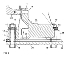
- a shoe 17 is arranged.
- the mounting foot 10 is connected via a mounting flange 13 and a screw 14 (or an equivalent fastening means) to the housing of the exhaust gas turbocharger, in this case the turbine housing 20.
- a mounting flange 13 for attachment to the console 30 includes the Mounting foot 10 a plurality of mounting extensions 11, each having a mounting hole 12 for receiving a fastening means, in particular a screw 18, have.
- the sliding shoe 17 is clamped between the attachment runner 11 and the bracket 30.
- the fastening bore 12 in the fastening runner 11 is designed in such a way that the fastening runner 11 can move on the slide shoe 17 relative to the screw 18.
- the shear forces on the screws 18 in operation are not too large when the shoe 17 threatens to move about relative to the console 30, according to the invention, the force is divided differently in the attachment direction to the various components.
- slide bushing 16 is stronger pressed against the console 30 as the mounting tail 11 against the shoe 17. Between shoe 17 and console 30 thus it comes to a frictional connection.
- nut and screw can also be arranged reversed - such as in Fig. 1 - or other fasteners can be used instead of screw and nut.
- This effect can be further enhanced by special treatment of the surfaces (surface quality, surface texture with respect to material or structure) or a coating property influencing coating, such as the contact surfaces between shoe 17 and console 30 roughened or smoothed the contact surfaces between mounting runners 11 and shoe and / / or hardened.
- a sliding element can be arranged between the spring assembly 15 and the support surface on the attachment runner 11 of the mounting foot 10, which allows a better sliding of the spring assemblies on the support surface on the mounting run with constant force transmission in the fastening direction.
- a directed sliding of the mounting foot can be forced on the shoe.
- a projection on the shoe is guided in a corresponding groove on the mounting foot.
- Other guide elements, such as feather keys, can be used for this purpose.
Landscapes
- Engineering & Computer Science (AREA)
- Chemical & Material Sciences (AREA)
- Combustion & Propulsion (AREA)
- Mechanical Engineering (AREA)
- General Engineering & Computer Science (AREA)
- Chemical Kinetics & Catalysis (AREA)
- General Chemical & Material Sciences (AREA)
- Supercharger (AREA)
Description
- Die Erfindung bezieht sich auf das Gebiet der Strömungsmaschinen, insbesondere der Abgasturbolader für aufgeladene Brennkraftmaschinen. Sie betrifft eine Befestigungsvorrichtung zur Befestigung eines solchen Abgasturboladers auf einem Untergrund, etwa der Konsole einer Brennkraftmaschine.
- Abgasturbolader werden zur Leistungssteigerung von Brennkraftmaschinen (Hubkolbenmotoren) eingesetzt. Ein Abgasturbolader besteht aus einer Abgasturbine im Abgasstrom der Brennkraftmaschine und einem Verdichter im Ansaugtrakt der Brennkraftmaschine. Das Turbinenrad der Abgasturbine wird vom Abgasstrom der Brennkraftmaschine in Rotation versetzt und treibt über eine Welle das Laufrad des Verdichters an. Der Verdichter erhöht den Druck im Ansaugtrakt der Brennkraftmaschine, so dass beim Ansaugen eine größere Menge Luft in die Brennkammern gelangt. Der Verdichter umfasst ein Verdichtergehäuse, welches in der Regel im radial äusseren Bereich mit langen Schrauben am Lagergehäuse befestigt ist.
- Zur Befestigung von Abgasturboladern auf einem Untergrund gibt es eine Reihe sehr unterschiedlicher Möglichkeiten. Da die heute eingesetzten Abgasturbolader meist ungekühlte Gehäuse aufweisen, stellt sich bei der Befestigung von Abgasturboladern auf meist verhältnismässig kühlem Untergrund das Problem von unterschiedlichen thermischen Ausdehnungen zwischen Abgasturbolader und Untergrund, welche zu Spannungen in der Befestigungsvorrichtung führen können. Um dieses Problem zu lösen werden in der Regel separate Befestigungsfüsse zwischen Abgasturbolader und Untergrund eingebracht, die durch spezielle Ausgestaltung die unterschiedlichen Ausdehnungen aufnehmen können. Ausserdem erlauben es diese Befestigungsfüsse oft auch eine räumlich variable Ausrichtung von zumindest Teilen des Gehäuses des Abgasturboladers. Separate Befestigungsfüsse der genannten Art sind beispielsweise aus
DE-A-44 32 073 oderDE-OS-36 41 478 - Die
EP 1 331 365 A1 offenbart eine Befestigungsvorrichtung zur Befestigung eines Turboladers an einem Untergrund vorgestellt. Die Befestigungsvorrichtung weist zwei im Untergrund fixierbare, axial voneinander beabstandete Füsse auf. Der zweite Fuss hat einen Gehäuseverbindungsbereich, der mit dem Turboladergehäuse verbindbar ist, und einen Untergrundverbindungsbereich, der mit dem Untergrund verbindbar ist. Der Gehäuseverbindungsbereich ist in Form eines Teilkreis- oder Kreisbogens ausgebildet. Eine Axialverstrebung verbindet den Gehäuseverbindungsbereich und den Untergrundverbindungsbereich und schliesst mit dem Untergrund einen Winkel im Bereich von 0° bis 60° ein. - Die
DE 43 35 485 A1 offenbart eine Einrichtung zur Befestigung eines Grossmaschinenteils auf einem zementierten Fundament, mit einem metallischen und in das Fundament kraftschlüssig einzementierten Anker, an dem das Grossmaschinenteil befestigbar ist. Zwischen dem Grossmaschinenteil und dem Fundament ist dabei eine Zwischenplatte vorgesehen, welche für die Befestigung des Grossmaschinenteils von untergeordneter Bedeutung ist. - Die
US 1,626,760 offenbart eine Grundplatte für Grossmotoren, welche einen Befestigungsfuss mit zwei verschiedenen Gruppen von Befestigungsöffnungen aufweist. Die erste Gruppe von Befestigungsöffnungen ist dabei für die Befestigung der Grundplatte an einem Untergrund, die zweite Gruppe der Befestigungsöffnungen für die Befestigung der Grundplatte auf einem Traggestell vorgesehen. - Die
US 2,190,170 offenbart eine Tragvorrichtung für einen Druckzylinder, bei welcher eine obere Zylinderhälfte und eine untere Zylinderhälfte miteinander verbunden sind. Die Verbindung wird mittels Befestigungsmitteln zusammengehalten, welche die untere Zylinderhälfte an einem Traggestell fixieren, jedoch eine Relativbewegung der oberen Zylinderhälfte zur unteren Zylinderhälfte zulassen. - Die
EP 1 176 286 offenbart einen an ein Gasaustrittsgehäuse einteilig angebauten Befestigungsfuss, welcher beabstandet voneinander Langlöcher aufweist, deren Längsachsen sternförmig in einem Zentrum zusammentreffen. In die Langlöcher sind Gleitschuhe einsetzbar, die in ihren durchgehenden Öffnungen Befestigungselemente, wie z.B. Schrauben aufnehmen. Mittels der Schrauben wird der einteilig an das Gasaustrittsgehäuse des Turboladers angebaute Befestigungsfuss und somit der Turbolader lösbar auf dem Untergrund befestigt. Mit Starten der mit dem Abgasturbolader verbundenen Brennkraftmaschine heizen sich das Gasaustrittsgehäuse und der angebaute Befestigungsfuss gegenüber dem Untergrund auf. Die Ausdehnung des sich aufheizenden Materials kann dabei bis zu mehrere Millimeter betragen. Statt nun die Schrauben wie bei einer normalen Schraubverbindung zwischen Befestigungsfuss und Untergrund auf Biegung zu belasten, bewegt sich das sich ausdehnende Material des Befestigungsfusses sozusagen unter den die Schrauben haltenden Gleitschuhen auf dem Untergrund. Die Schrauben bleiben in den Gleitschuhen spannungsfrei geführt, während eine Relativbewegung des Gleitschuhes im Langloch stattfindet. Auch nach mehreren Temperaturzyklen tritt somit keine Materialermüdung auf und ein Sicherheitsrisiko durch eventuelles Versagen der Befestigung besteht nicht. Ein allfälliger Materialverschleiss reduziert sich bei dieser Lösung auf den Bereich der Kontaktfläche zwischen dem Befestigungsfuss und dem Untergrund, zwischen den aufeinander gleitenden Bauteilen. - Die Aufgabe der vorliegenden Erfindung besteht darin, die Befestigungsvorrichtung zwischen dem Befestigungsfuss des Abgasturboladers und dem Untergrund derart zu verbessern, dass sowohl am Befestigungsfuss wie auch am Untergrund der Materialverschleiss reduziert werden kann.
- Erfindungsgemäss wird dies erreicht, indem zwischen dem Befestigungsfuss und dem Untergrund ein grossflächiger Gleitschuh angeordnet wird. Durch form- und/oder kraftschlüssige Verbindung von Untergrund und Gleitschuh, beziehungsweise unterschiedliche Gleiteigenschaften der Kontaktflächen zwischen Untergrund und Gleitschuh sowie zwischen Gleitschuh und Befestigungsfuss kann verhindert werden, dass der Befestigungsfuss unerwünschte Verschiebungen auf dem Untergrund erfährt. Damit kann der Materialverschleiss insbesondere am Untergrund reduziert werden.
- Nachfolgend wird eine Ausführungsform der Erfindung anhand von Zeichnungen detailliert erläutert. Hierbei zeigt
- Fig. 1
- eine Seitenansicht eines Abgasturboladers gemäss dem Stand der Technik, und
- Fig. 2
- einen Teilschnitt durch einen Abgasturbolader nach
Fig. 1 mit einer erfindungsgemässen Befestigungsvorrichtung. -
Fig. 1 zeigt in Seitenansicht entlang seiner Längsachse einen Abgasturbolader gemäss dem Stand der Technik. Der Abgasturbolader umfasst einen Verdichter in einem Verdichtergehäuse 40 sowie eine Abgasturbine in einem Turbinengehäuse 20. Dazwischen ist das Lagergehäuse 50 angeordnet, in welchem die Welle des Abgasturboladers drehbar gelagert ist. Das Verdichtergehäuse umfasst einen Lufteintritt 41 von wo aus die Luft über das Verdichterrad und einen spiralförmigen Sammelbehälter dem Luftaustritt 42 zugeführt wird. Lufteintrittsseitig kann anstelle eines Luftansaugstutzens 43 auch ein Schalldämpfer 44 angeordnet sein. Turbinenseitig wird das Abgas durch den Gaseintritt 21 auf das Turbinenrad geleitet und anschliessend durch den Gasaustritt dem Auspuff zugeführt. - Die Befestigung des Abgasturboladers erfolgt in der Regel mit zwei, axial voneinander beabstandeten Befestigungsfüssen 9 und 10. Ein erster Befestigungsfuss 9 trägt dabei die Hauptlast direkt unter dem Lagergehäuse 50 oder dem Turbinengehäuse 20. Ein zweiter, stützender Befestigungsfuss greift etwas weiter turbinenseitig am Turbinengehäuse 20 an.
- Dehnt sich der zweite Befestigungsfuss aufgrund der hohen Betriebstemperaturen im Turbinenbereich stärker aus als der darunter liegende Untergrund, kann es bei herkömmlichen Befestigungsvorrichtungen zu Spannungen und Materialverschleiss im Befestigungsfuss und/ oder an dem Untergrund kommen.
- Aus diesem Grund ist bei der erfindungsgemässen Befestigungsvorrichtung nach
Fig. 2 zwischen einer Kontaktfläche am Befestigungsfuss 10 und der den Untergrund bildenden Konsole 30 ein Gleitschuh 17 angeordnet. Der Befestigungsfuss 10 ist über einen Befestigungsflansch 13 und einer Schraube 14 (oder ein gleichwertiges Befestigungsmittel) mit dem Gehäuse des Abgasturboladers, in diesem Fall dem Turbinengehäuse 20 verbunden. Zur Befestigung auf der Konsole 30 umfasst der Befestigungsfuss 10 mehrere Befestigungsausläufer 11, welche jeweils eine Befestigungsbohrung 12 zur Aufnahme eines Befestigungsmittels, insbesondere einer Schraube 18, aufweisen. Im montierten Zustand ist zwischen dem Befestigungsausläufer 11 und der Konsole 30 der Gleitschuh 17 eingeklemmt. Erfindungsgemäss ist dabei die Befestigungsbohrung 12 im Befestigungsausläufer 11 derart ausgestaltet, dass sich der Befestigungsausläufer 11 auf dem Gleitschuh 17 relativ zur Schraube 18 bewegen kann. Die Bohrungen im Gleitschuh 17 und in der Konsole 30 hingegen, umfassen die Schraube 18 formschlüssig. Dadurch ist sichergestellt, dass Schraube 18, Gleitschuh 17 und Konsole 30 relativ zueinander nicht bewegt werden können. Auf der Kontaktfläche B der Konsole 30 findet somit keine Verschiebung statt. Die einzige zugelassene Verschiebung findet zwischen der Kontaktfläche A der Befestigungsausläufer 11 des Befestigungsfusses 10 und dem Gleitschuh 17 statt. - Damit die Scherkräfte auf die Schrauben 18 im Betrieb nicht zu gross werden, wenn der Gleitschuh 17 etwa relativ zur Konsole 30 zu verschieben droht, wird erfindungsgemäss die Kraft in Befestigungsrichtung auf die verschiedenen Bauteile unterschiedlich aufgeteilt.
- Durch eine Gleitbuchse 16, welche als integriertes oder separates Bauteil mit dem Gleitschuh verbunden ist, sowie über ein Tellerfederpaket 15, wird die mit der Schraube 18 und der Mutter 19 bewirkte Kraft aufgeteilt. Beim Festschrauben der Mutter 19 auf dem Gewinde der Schraube 18 wird das Tellerfederpaket 15 in Befestigungsrichtung (also senkrecht zur Befestigungsebene auf der Konsole) zusammengepresst, bis es im radial inneren Bereich auf der gegenüber dem Befestigungsausläufer 11 leicht überhöhten, aus der Befestigungsöffnung 12 geringfügig herausragenden Gleitbuchse 16 aufliegt. Wird die Mutter 19 nun weiter angezogen, erhöht sich die Befestigungskraft auf die Gleitbuchse (grosse Pfeile) stärker als die ebenfalls in Befestigungsrichtung wirkende Kraft auf den Befestigungsausläufer (kleine Pfeile). Somit wird die Gleitbuchse 16 stärker gegen die Konsole 30 gepresst als der Befestigungsausläufer 11 gegen den Gleitschuh 17. Zwischen Gleitschuh 17 und Konsole 30 kommt es somit zu einem Kraftschluss. Natürlich können Mutter und Schraube auch vertauscht angeordnet sein - wie etwa in
Fig. 1 -, oder es können andere Befestigungsmittel anstelle von Schraube und Mutter eingesetzt werden. - Bei gleicher Beschaffenheit der Oberflächen von Konsole 30, Gleitschuh 17 und Befestigungsausläufer 11 kommt es im Falle einer horizontalen Verschiebung des Befestigungsfusses dank der erfindungsgemässen Befestigungsvorrichtung zu einer Relativbewegung zwischen Befestigungsausläufer 11 und Gleitschuh17.
- Dieser Effekt kann durch spezielle Bearbeitung der Oberflächen (Oberflächengüte, Oberflächenbeschaffenheit bezüglich Material oder Struktur) oder einer die Gleiteigenschaft beeinflussenden Beschichtung weiter verstärkt werden, etwa indem die Kontaktflächen zwischen Gleitschuh 17 und Konsole 30 aufgeraut oder aber die Kontaktflächen zwischen Befestigungsausläufer 11 und Gleitschuh geglättet und/ oder gehärtet werden.
- Zwischen dem Federpaket 15 und der Auflagefläche am Befestigungsausläufer 11 des Befestigungsfusses 10 kann optional ein Gleitelement angeordnet sein, welches ein besseres Gleiten der Federpakete auf der Auflagefläche am Befestigungsausläufer bei gleich bleibender Kraftübertragung in Befestigungsrichtung ermöglicht.
- Durch Einlegen eines Führungselementes kann ein gerichtetes Gleiten des Befestigungsfusses auf dem Gleitschuh erzwungen werden. Dabei wird beispielsweise ein Vorsprung auf dem Gleitschuh in einer entsprechenden Nut am Befestigungsfuss geführt. Auch andere Führungselemente, wie etwa Passfedern, können hierfür eingesetzt werden.
-
- 9, 10
- Befestigungsfuss
- 11
- Befestigungsausläufer
- 12
- Befestigungsbohrung
- 13
- Befestigungsflansch
- 14
- Schraube (Befestigungsmittel)
- 15
- Tellerfedern (Federelement)
- 16
- Gleitbuchse
- 17
- Gleitschuh
- 18
- Schraube (Befestigungsmittel)
- 19
- Mutter (Befestigungsmittel)
- 20
- Turbinengehäuse
- 21
- Gaseintritt
- 22
- Gasaustritt
- 30
- Befestigungskonsole
- 40
- Verdichtergehäuse
- 41
- Luftaustritt
- 42
- Lufteintritt
- 43
- Luftansaugstutzen
- 44
- Schalldämpfer
- A
- Kontaktfläche des Befestigungsfusses
- B
- Kontaktfläche der Konsole
Claims (8)
- Befestigungsvorrichtung für die Befestigung eines Abgasturboladers auf einer Konsole (30), umfassend einen Befestigungsfuss (10) mit einer Befestigungsbohrung (12) sowie in dieser Befestigungsbohrung (12) lose geführte Befestigungsmittel (18, 19), dadurch gekennzeichnet, dass zwischen einer Kontaktfläche (A) des Befestigungsfusses (10) und einer Kontaktfläche (B) der Konsole (30) ein Gleitschuh (17) angeordnet ist, welcher Gleitschuh (17) mit der Kontaktfläche (A) des Befestigungsfusses (10) eine Gleitfläche bildet, entlang welcher der Befestigungsfuss (10) relativ zum Gleitschuh (17) und dem Befestigungsmittel (18, 19) bewegt werden kann, und welcher Gleitschuh (17) mittels der Befestigungsmittel (18, 19) formschlüssig mit der Konsole (30) verbunden ist, so dass Befestigungsmittel (18, 19), Gleitschuh (17) und Konsole (30) relativ zueinander nicht bewegt werden können, so dass die einzige zugelassene Verschiebung des Gleitschuhs (17) auf der Kontaktfläche (A) des Befestigungsfusses (10) stattfinden kann und auf der Kontaktfläche (B) der Konsole (30) keine Verschiebung des Gleitschuhs (17) stattfinden kann.
- Befestigungsvorrichtung nach Anspruch 1, wobei der Gleitschuh (17) eine Gleitbuchse (16) umfasst, welche in der Befestigungsbohrung (12) angeordnet ist und der Kraftübertragung vom Befestigungsmittel (18, 19) auf die Konsole (30) dient, wobei die Gleitbuchse (16) gegenüber dem Befestigungsfuss (10) in Befestigungsrichtung eine grössere Länge aufweist und an dem der Konsole abgewandten Ende der Befestigungsbohrung (12) aus der Befestigungsbohrung (12) herausragt.
- Befestigungsvorrichtung nach Anspruch 2, wobei die Befestigungsmittel (18, 19) Kräfte in Befestigungsrichtung bewirken und diese Kräfte mittels Federelementen (15) unterschiedlich stark auf die Gleitbuchse (16) und den Befestigungsfuss (10) aufgeteilt werden.
- Befestigungsvorrichtung nach Anspruch 3, wobei die Kräfte auf die Gleitbuchse (16) und den Befestigungsfuss (10) mittels Tellerfedern (15) aufgeteilt werden.
- Befestigungsvorrichtung nach einem der Ansprüche 1 bis 4, wobei die Kontaktfläche (A) des Befestigungsfusses und/ oder die mit dieser die Gleitfläche bildende Oberfläche des Gleitschuhs (17) zur verbesserten Gleitfähigkeit bearbeitet oder beschichtet ist.
- Befestigungsvorrichtung nach einem der Ansprüche 1 bis 5, wobei die Kontaktfläche (B) der Konsole und/ oder die auf dieser aufliegende Oberfläche des Gleitschuhs (17) zur verbesserten Haftung bearbeitet oder beschichtet ist.
- Abgasturbolader, umfassend eine Befestigungsvorrichtung nach einem der Ansprüche 1 bis 6.
- Brennkraftmaschine und Abgasturbolader, umfassend eine Befestigungsvorrichtung für die Befestigung des Abgasturboladers auf einer Konsole (30) der Brennkraftmaschine nach einem der Ansprüche 1 bis 6.
Priority Applications (1)
| Application Number | Priority Date | Filing Date | Title |
|---|---|---|---|
| EP09712699.9A EP2250348B1 (de) | 2008-02-18 | 2009-02-17 | Befestigungsvorrichtung für einen abgasturbolader |
Applications Claiming Priority (3)
| Application Number | Priority Date | Filing Date | Title |
|---|---|---|---|
| EP08151571A EP2090756A1 (de) | 2008-02-18 | 2008-02-18 | Befestigungsvorrichtung für einen Abgasturbolader |
| EP09712699.9A EP2250348B1 (de) | 2008-02-18 | 2009-02-17 | Befestigungsvorrichtung für einen abgasturbolader |
| PCT/EP2009/051830 WO2009103691A1 (de) | 2008-02-18 | 2009-02-17 | Befestigungsvorrichtung für einen abgasturbolader |
Publications (2)
| Publication Number | Publication Date |
|---|---|
| EP2250348A1 EP2250348A1 (de) | 2010-11-17 |
| EP2250348B1 true EP2250348B1 (de) | 2015-09-16 |
Family
ID=39772919
Family Applications (2)
| Application Number | Title | Priority Date | Filing Date |
|---|---|---|---|
| EP08151571A Withdrawn EP2090756A1 (de) | 2008-02-18 | 2008-02-18 | Befestigungsvorrichtung für einen Abgasturbolader |
| EP09712699.9A Active EP2250348B1 (de) | 2008-02-18 | 2009-02-17 | Befestigungsvorrichtung für einen abgasturbolader |
Family Applications Before (1)
| Application Number | Title | Priority Date | Filing Date |
|---|---|---|---|
| EP08151571A Withdrawn EP2090756A1 (de) | 2008-02-18 | 2008-02-18 | Befestigungsvorrichtung für einen Abgasturbolader |
Country Status (5)
| Country | Link |
|---|---|
| EP (2) | EP2090756A1 (de) |
| JP (1) | JP5001438B2 (de) |
| KR (1) | KR101215216B1 (de) |
| CN (1) | CN101952558B (de) |
| WO (1) | WO2009103691A1 (de) |
Families Citing this family (4)
| Publication number | Priority date | Publication date | Assignee | Title |
|---|---|---|---|---|
| US8616517B2 (en) | 2008-12-22 | 2013-12-31 | Siemens Aktiengesellschaft | Turbomachine foot unit |
| CN102425462A (zh) * | 2011-12-07 | 2012-04-25 | 哈尔滨汽轮机厂有限责任公司 | 一种供热汽轮机联通管蝶阀的弹性支撑装置 |
| DE102017104001A1 (de) * | 2017-02-27 | 2018-08-30 | Man Diesel & Turbo Se | Turbolader |
| KR102007138B1 (ko) * | 2019-01-22 | 2019-08-02 | 한전케이피에스 주식회사 | 터빈 로터 가이드 장치 |
Family Cites Families (14)
| Publication number | Priority date | Publication date | Assignee | Title |
|---|---|---|---|---|
| US1626760A (en) * | 1921-04-19 | 1927-05-03 | Busch Sulzer Brosdiesel Engine | Engine bedplate |
| US2190170A (en) * | 1938-04-06 | 1940-02-13 | Westinghouse Electric & Mfg Co | Cylinder supporting arrangement |
| JPS60155730U (ja) * | 1984-03-26 | 1985-10-17 | 川崎重工業株式会社 | 排気タ−ボチヤ−ジヤの取付構造 |
| DE3641478A1 (de) | 1986-12-04 | 1988-06-16 | Klein Schanzlin & Becker Ag | Gehaeusetraeger fuer stroemungsmaschinen |
| JPH08491Y2 (ja) * | 1990-02-09 | 1996-01-10 | 石川島播磨重工業株式会社 | 機械駆動式過給機の設置構造 |
| DE4335485A1 (de) * | 1993-10-18 | 1995-04-20 | Siemens Ag | Einrichtung zur Befestigung eines Großmaschinenteils auf einem zementierten Fundament |
| DE4432073C2 (de) | 1994-09-09 | 2002-11-28 | Abb Turbo Systems Ag Baden | Vorrichtung zur Befestigung von Turboladern |
| DE50010566D1 (de) | 2000-07-26 | 2005-07-21 | Abb Turbo Systems Ag Baden | Vorrichtung zur Befestigung einesTurboladers |
| DE50013694D1 (de) * | 2000-09-08 | 2006-12-14 | Abb Turbo Systems Ag | Befestigungsvorrichtung für einen Filterschalldämpfer am Verdichtereingang eines Turboladers |
| DE10116090C2 (de) * | 2001-03-30 | 2003-04-30 | Messer Cutting & Welding Gmbh | Laufbahn für eine Werkzeugmaschine |
| DE10155224A1 (de) * | 2001-11-09 | 2003-05-22 | Bosch Gmbh Robert | Lüfterrad für elektrische Maschinen |
| EP1331365A1 (de) * | 2002-01-29 | 2003-07-30 | ABB Turbo Systems AG | Befestigungsvorrichtung für einen Turbolader |
| DE102004028125B3 (de) * | 2004-06-09 | 2006-03-30 | Borgwarner Inc., Auburn Hills | Axialgleitlager für einen Abgasturbolader |
| EP1669548A1 (de) * | 2004-12-08 | 2006-06-14 | ABB Turbo Systems AG | Leitapparat für Abgasturbine |
-
2008
- 2008-02-18 EP EP08151571A patent/EP2090756A1/de not_active Withdrawn
-
2009
- 2009-02-17 KR KR1020107018510A patent/KR101215216B1/ko active Active
- 2009-02-17 EP EP09712699.9A patent/EP2250348B1/de active Active
- 2009-02-17 CN CN200980106202.1A patent/CN101952558B/zh active Active
- 2009-02-17 WO PCT/EP2009/051830 patent/WO2009103691A1/de not_active Ceased
- 2009-02-17 JP JP2010546361A patent/JP5001438B2/ja active Active
Also Published As
| Publication number | Publication date |
|---|---|
| JP2011512476A (ja) | 2011-04-21 |
| EP2090756A1 (de) | 2009-08-19 |
| EP2250348A1 (de) | 2010-11-17 |
| CN101952558A (zh) | 2011-01-19 |
| CN101952558B (zh) | 2014-01-01 |
| KR101215216B1 (ko) | 2012-12-24 |
| JP5001438B2 (ja) | 2012-08-15 |
| KR20100102730A (ko) | 2010-09-24 |
| WO2009103691A1 (de) | 2009-08-27 |
Similar Documents
| Publication | Publication Date | Title |
|---|---|---|
| EP1483482B1 (de) | Leitschaufelbefestigung in einem strömungskanal einer fluggasturbine | |
| EP1460237B1 (de) | Abgasturbinengehäuse | |
| DE4037410C2 (de) | ||
| EP2209969B1 (de) | Ladeeinrichtung | |
| DE102016002701A1 (de) | Turboladerturbinenanordnung | |
| WO2011003681A1 (de) | Nockenwellenversteller | |
| EP3293386B1 (de) | Mischerbaugruppe für ein turbofan-triebwerk | |
| EP2845999A2 (de) | Verfahren zum Auswuchten und zur Montage eines Turbinenrotors | |
| EP3404207A1 (de) | Rotoranordnung mit wuchtelement und verfahren zur montage eines wuchtelements | |
| DE102005001864B3 (de) | Turbinengehäuse eines Abgasturboladers mit verstellbarer Turbinengeometrie | |
| DE102008019156A1 (de) | Strebe für ein Turbinenzwischengehäuse, Turbinenzwischengehäuse und Verfahren zur Herstellung eines Turbinenzwischengehäuses | |
| EP2090755A1 (de) | Turboladergehäuse | |
| EP1462616B1 (de) | Anordnung für das axiale und radiale Festlegen einer Leitschaufelbaugruppe in dem Gehäuse eines Turbinentriebwerkes | |
| EP2090756A1 (de) | Befestigungsvorrichtung für einen Abgasturbolader | |
| EP3327257A1 (de) | Leitschaufelbaugruppe mit ausgleichseinrichtung | |
| EP1712744A1 (de) | Anordnung zur inneren passiven Laufspalteinstellung bei einer Hochdruckturbine | |
| WO2012004336A2 (de) | Verdichter | |
| DE112019005526B4 (de) | Turbolader | |
| EP3176386B1 (de) | Innenringsystem, zugehöriger innenring, zwichengehäuse und strömungsmaschine | |
| EP1598525A1 (de) | Turboladerstütze | |
| EP1860284A1 (de) | Gehäuseverbindung | |
| EP3327256B1 (de) | Leitschaufelbaugruppe mit ausgleichseinrichtung | |
| CH702203A1 (de) | Rotor für eine axial durchströmte turbomaschine sowie laufschaufel für einen solchen rotor. | |
| EP1965037A1 (de) | Axiale und radiale Lagerung des Stellrings für Eintrittsleitapparate bei Heissgasexpandern | |
| EP2796665B1 (de) | Abgasturbolader mit einer Welle aus unterschiedlichen Materialien |
Legal Events
| Date | Code | Title | Description |
|---|---|---|---|
| PUAI | Public reference made under article 153(3) epc to a published international application that has entered the european phase |
Free format text: ORIGINAL CODE: 0009012 |
|
| 17P | Request for examination filed |
Effective date: 20100810 |
|
| AK | Designated contracting states |
Kind code of ref document: A1 Designated state(s): AT BE BG CH CY CZ DE DK EE ES FI FR GB GR HR HU IE IS IT LI LT LU LV MC MK MT NL NO PL PT RO SE SI SK TR |
|
| AX | Request for extension of the european patent |
Extension state: AL BA RS |
|
| RIN1 | Information on inventor provided before grant (corrected) |
Inventor name: SCHELLENBERG, PETER Inventor name: BAETTIG, JOSEF Inventor name: OESCHGER, DANIEL Inventor name: FLURY, BALZ |
|
| DAX | Request for extension of the european patent (deleted) | ||
| 17Q | First examination report despatched |
Effective date: 20141211 |
|
| GRAP | Despatch of communication of intention to grant a patent |
Free format text: ORIGINAL CODE: EPIDOSNIGR1 |
|
| INTG | Intention to grant announced |
Effective date: 20150609 |
|
| GRAS | Grant fee paid |
Free format text: ORIGINAL CODE: EPIDOSNIGR3 |
|
| GRAA | (expected) grant |
Free format text: ORIGINAL CODE: 0009210 |
|
| AK | Designated contracting states |
Kind code of ref document: B1 Designated state(s): AT BE BG CH CY CZ DE DK EE ES FI FR GB GR HR HU IE IS IT LI LT LU LV MC MK MT NL NO PL PT RO SE SI SK TR |
|
| REG | Reference to a national code |
Ref country code: GB Ref legal event code: FG4D Free format text: NOT ENGLISH |
|
| REG | Reference to a national code |
Ref country code: CH Ref legal event code: EP |
|
| REG | Reference to a national code |
Ref country code: IE Ref legal event code: FG4D Free format text: LANGUAGE OF EP DOCUMENT: GERMAN |
|
| REG | Reference to a national code |
Ref country code: AT Ref legal event code: REF Ref document number: 750001 Country of ref document: AT Kind code of ref document: T Effective date: 20151015 |
|
| REG | Reference to a national code |
Ref country code: DE Ref legal event code: R096 Ref document number: 502009011584 Country of ref document: DE |
|
| REG | Reference to a national code |
Ref country code: NL Ref legal event code: MP Effective date: 20150916 |
|
| PG25 | Lapsed in a contracting state [announced via postgrant information from national office to epo] |
Ref country code: NO Free format text: LAPSE BECAUSE OF FAILURE TO SUBMIT A TRANSLATION OF THE DESCRIPTION OR TO PAY THE FEE WITHIN THE PRESCRIBED TIME-LIMIT Effective date: 20151216 Ref country code: LT Free format text: LAPSE BECAUSE OF FAILURE TO SUBMIT A TRANSLATION OF THE DESCRIPTION OR TO PAY THE FEE WITHIN THE PRESCRIBED TIME-LIMIT Effective date: 20150916 Ref country code: FI Free format text: LAPSE BECAUSE OF FAILURE TO SUBMIT A TRANSLATION OF THE DESCRIPTION OR TO PAY THE FEE WITHIN THE PRESCRIBED TIME-LIMIT Effective date: 20150916 Ref country code: GR Free format text: LAPSE BECAUSE OF FAILURE TO SUBMIT A TRANSLATION OF THE DESCRIPTION OR TO PAY THE FEE WITHIN THE PRESCRIBED TIME-LIMIT Effective date: 20151217 Ref country code: LV Free format text: LAPSE BECAUSE OF FAILURE TO SUBMIT A TRANSLATION OF THE DESCRIPTION OR TO PAY THE FEE WITHIN THE PRESCRIBED TIME-LIMIT Effective date: 20150916 |
|
| REG | Reference to a national code |
Ref country code: LT Ref legal event code: MG4D |
|
| PG25 | Lapsed in a contracting state [announced via postgrant information from national office to epo] |
Ref country code: HR Free format text: LAPSE BECAUSE OF FAILURE TO SUBMIT A TRANSLATION OF THE DESCRIPTION OR TO PAY THE FEE WITHIN THE PRESCRIBED TIME-LIMIT Effective date: 20150916 Ref country code: SE Free format text: LAPSE BECAUSE OF FAILURE TO SUBMIT A TRANSLATION OF THE DESCRIPTION OR TO PAY THE FEE WITHIN THE PRESCRIBED TIME-LIMIT Effective date: 20150916 |
|
| PG25 | Lapsed in a contracting state [announced via postgrant information from national office to epo] |
Ref country code: NL Free format text: LAPSE BECAUSE OF FAILURE TO SUBMIT A TRANSLATION OF THE DESCRIPTION OR TO PAY THE FEE WITHIN THE PRESCRIBED TIME-LIMIT Effective date: 20150916 |
|
| PG25 | Lapsed in a contracting state [announced via postgrant information from national office to epo] |
Ref country code: EE Free format text: LAPSE BECAUSE OF FAILURE TO SUBMIT A TRANSLATION OF THE DESCRIPTION OR TO PAY THE FEE WITHIN THE PRESCRIBED TIME-LIMIT Effective date: 20150916 Ref country code: SK Free format text: LAPSE BECAUSE OF FAILURE TO SUBMIT A TRANSLATION OF THE DESCRIPTION OR TO PAY THE FEE WITHIN THE PRESCRIBED TIME-LIMIT Effective date: 20150916 Ref country code: IT Free format text: LAPSE BECAUSE OF FAILURE TO SUBMIT A TRANSLATION OF THE DESCRIPTION OR TO PAY THE FEE WITHIN THE PRESCRIBED TIME-LIMIT Effective date: 20150916 Ref country code: IS Free format text: LAPSE BECAUSE OF FAILURE TO SUBMIT A TRANSLATION OF THE DESCRIPTION OR TO PAY THE FEE WITHIN THE PRESCRIBED TIME-LIMIT Effective date: 20160116 Ref country code: ES Free format text: LAPSE BECAUSE OF FAILURE TO SUBMIT A TRANSLATION OF THE DESCRIPTION OR TO PAY THE FEE WITHIN THE PRESCRIBED TIME-LIMIT Effective date: 20150916 |
|
| PG25 | Lapsed in a contracting state [announced via postgrant information from national office to epo] |
Ref country code: PL Free format text: LAPSE BECAUSE OF FAILURE TO SUBMIT A TRANSLATION OF THE DESCRIPTION OR TO PAY THE FEE WITHIN THE PRESCRIBED TIME-LIMIT Effective date: 20150916 Ref country code: PT Free format text: LAPSE BECAUSE OF FAILURE TO SUBMIT A TRANSLATION OF THE DESCRIPTION OR TO PAY THE FEE WITHIN THE PRESCRIBED TIME-LIMIT Effective date: 20160118 Ref country code: BE Free format text: LAPSE BECAUSE OF NON-PAYMENT OF DUE FEES Effective date: 20160229 Ref country code: RO Free format text: LAPSE BECAUSE OF FAILURE TO SUBMIT A TRANSLATION OF THE DESCRIPTION OR TO PAY THE FEE WITHIN THE PRESCRIBED TIME-LIMIT Effective date: 20150916 |
|
| REG | Reference to a national code |
Ref country code: DE Ref legal event code: R097 Ref document number: 502009011584 Country of ref document: DE |
|
| PLBE | No opposition filed within time limit |
Free format text: ORIGINAL CODE: 0009261 |
|
| STAA | Information on the status of an ep patent application or granted ep patent |
Free format text: STATUS: NO OPPOSITION FILED WITHIN TIME LIMIT |
|
| 26N | No opposition filed |
Effective date: 20160617 |
|
| PG25 | Lapsed in a contracting state [announced via postgrant information from national office to epo] |
Ref country code: DK Free format text: LAPSE BECAUSE OF FAILURE TO SUBMIT A TRANSLATION OF THE DESCRIPTION OR TO PAY THE FEE WITHIN THE PRESCRIBED TIME-LIMIT Effective date: 20150916 |
|
| PG25 | Lapsed in a contracting state [announced via postgrant information from national office to epo] |
Ref country code: LU Free format text: LAPSE BECAUSE OF FAILURE TO SUBMIT A TRANSLATION OF THE DESCRIPTION OR TO PAY THE FEE WITHIN THE PRESCRIBED TIME-LIMIT Effective date: 20160217 Ref country code: MC Free format text: LAPSE BECAUSE OF FAILURE TO SUBMIT A TRANSLATION OF THE DESCRIPTION OR TO PAY THE FEE WITHIN THE PRESCRIBED TIME-LIMIT Effective date: 20150916 |
|
| REG | Reference to a national code |
Ref country code: CH Ref legal event code: PL |
|
| PG25 | Lapsed in a contracting state [announced via postgrant information from national office to epo] |
Ref country code: LI Free format text: LAPSE BECAUSE OF NON-PAYMENT OF DUE FEES Effective date: 20160229 Ref country code: CH Free format text: LAPSE BECAUSE OF NON-PAYMENT OF DUE FEES Effective date: 20160229 |
|
| REG | Reference to a national code |
Ref country code: FR Ref legal event code: ST Effective date: 20161028 |
|
| PG25 | Lapsed in a contracting state [announced via postgrant information from national office to epo] |
Ref country code: SI Free format text: LAPSE BECAUSE OF FAILURE TO SUBMIT A TRANSLATION OF THE DESCRIPTION OR TO PAY THE FEE WITHIN THE PRESCRIBED TIME-LIMIT Effective date: 20150916 |
|
| REG | Reference to a national code |
Ref country code: IE Ref legal event code: MM4A |
|
| PG25 | Lapsed in a contracting state [announced via postgrant information from national office to epo] |
Ref country code: IE Free format text: LAPSE BECAUSE OF NON-PAYMENT OF DUE FEES Effective date: 20160217 Ref country code: FR Free format text: LAPSE BECAUSE OF NON-PAYMENT OF DUE FEES Effective date: 20160229 |
|
| REG | Reference to a national code |
Ref country code: AT Ref legal event code: MM01 Ref document number: 750001 Country of ref document: AT Kind code of ref document: T Effective date: 20160217 |
|
| PG25 | Lapsed in a contracting state [announced via postgrant information from national office to epo] |
Ref country code: AT Free format text: LAPSE BECAUSE OF NON-PAYMENT OF DUE FEES Effective date: 20160217 |
|
| PG25 | Lapsed in a contracting state [announced via postgrant information from national office to epo] |
Ref country code: MT Free format text: LAPSE BECAUSE OF FAILURE TO SUBMIT A TRANSLATION OF THE DESCRIPTION OR TO PAY THE FEE WITHIN THE PRESCRIBED TIME-LIMIT Effective date: 20150916 |
|
| PG25 | Lapsed in a contracting state [announced via postgrant information from national office to epo] |
Ref country code: CY Free format text: LAPSE BECAUSE OF FAILURE TO SUBMIT A TRANSLATION OF THE DESCRIPTION OR TO PAY THE FEE WITHIN THE PRESCRIBED TIME-LIMIT Effective date: 20150916 Ref country code: HU Free format text: LAPSE BECAUSE OF FAILURE TO SUBMIT A TRANSLATION OF THE DESCRIPTION OR TO PAY THE FEE WITHIN THE PRESCRIBED TIME-LIMIT; INVALID AB INITIO Effective date: 20090217 |
|
| PG25 | Lapsed in a contracting state [announced via postgrant information from national office to epo] |
Ref country code: TR Free format text: LAPSE BECAUSE OF FAILURE TO SUBMIT A TRANSLATION OF THE DESCRIPTION OR TO PAY THE FEE WITHIN THE PRESCRIBED TIME-LIMIT Effective date: 20150916 Ref country code: MK Free format text: LAPSE BECAUSE OF FAILURE TO SUBMIT A TRANSLATION OF THE DESCRIPTION OR TO PAY THE FEE WITHIN THE PRESCRIBED TIME-LIMIT Effective date: 20150916 |
|
| PG25 | Lapsed in a contracting state [announced via postgrant information from national office to epo] |
Ref country code: BG Free format text: LAPSE BECAUSE OF FAILURE TO SUBMIT A TRANSLATION OF THE DESCRIPTION OR TO PAY THE FEE WITHIN THE PRESCRIBED TIME-LIMIT Effective date: 20150916 |
|
| REG | Reference to a national code |
Ref country code: DE Ref legal event code: R081 Ref document number: 502009011584 Country of ref document: DE Owner name: TURBO SYSTEMS SWITZERLAND LTD., CH Free format text: FORMER OWNER: ABB TURBO SYSTEMS AG, BADEN, CH Ref country code: DE Ref legal event code: R082 Ref document number: 502009011584 Country of ref document: DE Representative=s name: ZIMMERMANN & PARTNER PATENTANWAELTE MBB, DE Ref country code: DE Ref legal event code: R081 Ref document number: 502009011584 Country of ref document: DE Owner name: ABB SCHWEIZ AG, CH Free format text: FORMER OWNER: ABB TURBO SYSTEMS AG, BADEN, CH |
|
| REG | Reference to a national code |
Ref country code: GB Ref legal event code: 732E Free format text: REGISTERED BETWEEN 20210225 AND 20210303 |
|
| REG | Reference to a national code |
Ref country code: GB Ref legal event code: 732E Free format text: REGISTERED BETWEEN 20210304 AND 20210310 |
|
| REG | Reference to a national code |
Ref country code: GB Ref legal event code: 732E Free format text: REGISTERED BETWEEN 20220922 AND 20220928 |
|
| REG | Reference to a national code |
Ref country code: DE Ref legal event code: R081 Ref document number: 502009011584 Country of ref document: DE Owner name: TURBO SYSTEMS SWITZERLAND LTD., CH Free format text: FORMER OWNER: ABB SCHWEIZ AG, BADEN, CH Ref country code: DE Ref legal event code: R081 Ref document number: 502009011584 Country of ref document: DE Owner name: ACCELLERON SWITZERLAND LTD., CH Free format text: FORMER OWNER: ABB SCHWEIZ AG, BADEN, CH |
|
| REG | Reference to a national code |
Ref country code: DE Ref legal event code: R081 Ref document number: 502009011584 Country of ref document: DE Owner name: ACCELLERON SWITZERLAND LTD., CH Free format text: FORMER OWNER: TURBO SYSTEMS SWITZERLAND LTD., BADEN, CH |
|
| PGFP | Annual fee paid to national office [announced via postgrant information from national office to epo] |
Ref country code: GB Payment date: 20260219 Year of fee payment: 18 |
|
| PGFP | Annual fee paid to national office [announced via postgrant information from national office to epo] |
Ref country code: DE Payment date: 20260218 Year of fee payment: 18 |
|
| PGFP | Annual fee paid to national office [announced via postgrant information from national office to epo] |
Ref country code: CZ Payment date: 20260212 Year of fee payment: 18 |