EP2249372B1 - Procédé de réglage de l'énergie des ions dans des plasmas radiofréquences - Google Patents
Procédé de réglage de l'énergie des ions dans des plasmas radiofréquences Download PDFInfo
- Publication number
- EP2249372B1 EP2249372B1 EP10170734A EP10170734A EP2249372B1 EP 2249372 B1 EP2249372 B1 EP 2249372B1 EP 10170734 A EP10170734 A EP 10170734A EP 10170734 A EP10170734 A EP 10170734A EP 2249372 B1 EP2249372 B1 EP 2249372B1
- Authority
- EP
- European Patent Office
- Prior art keywords
- plasma
- voltage
- electrode
- ion
- harmonic
- Prior art date
- Legal status (The legal status is an assumption and is not a legal conclusion. Google has not performed a legal analysis and makes no representation as to the accuracy of the status listed.)
- Not-in-force
Links
- 238000000034 method Methods 0.000 title claims abstract description 82
- 210000002381 plasma Anatomy 0.000 title description 183
- 239000000758 substrate Substances 0.000 claims description 39
- 238000004519 manufacturing process Methods 0.000 claims description 28
- 239000004065 semiconductor Substances 0.000 claims description 14
- 230000004048 modification Effects 0.000 claims description 9
- 238000012986 modification Methods 0.000 claims description 9
- 239000002105 nanoparticle Substances 0.000 claims description 4
- 238000004544 sputter deposition Methods 0.000 claims description 3
- 238000004140 cleaning Methods 0.000 claims description 2
- 238000004132 cross linking Methods 0.000 claims description 2
- 229920000642 polymer Polymers 0.000 claims description 2
- 238000001020 plasma etching Methods 0.000 claims 2
- 238000000427 thin-film deposition Methods 0.000 claims 1
- 150000002500 ions Chemical class 0.000 description 182
- 230000004907 flux Effects 0.000 description 62
- 230000000694 effects Effects 0.000 description 36
- 230000008901 benefit Effects 0.000 description 32
- 238000009832 plasma treatment Methods 0.000 description 20
- 230000008569 process Effects 0.000 description 18
- 230000008859 change Effects 0.000 description 16
- 238000005530 etching Methods 0.000 description 12
- 230000005684 electric field Effects 0.000 description 9
- 238000005259 measurement Methods 0.000 description 8
- 238000004088 simulation Methods 0.000 description 8
- 239000000463 material Substances 0.000 description 6
- 230000003068 static effect Effects 0.000 description 6
- 238000013461 design Methods 0.000 description 5
- 239000007789 gas Substances 0.000 description 5
- 238000012545 processing Methods 0.000 description 5
- 239000010409 thin film Substances 0.000 description 5
- 235000012431 wafers Nutrition 0.000 description 5
- 210000004027 cell Anatomy 0.000 description 4
- 230000001419 dependent effect Effects 0.000 description 4
- 239000002245 particle Substances 0.000 description 4
- 238000000342 Monte Carlo simulation Methods 0.000 description 3
- XUIMIQQOPSSXEZ-UHFFFAOYSA-N Silicon Chemical compound [Si] XUIMIQQOPSSXEZ-UHFFFAOYSA-N 0.000 description 3
- 230000001133 acceleration Effects 0.000 description 3
- 238000004364 calculation method Methods 0.000 description 3
- 238000004590 computer program Methods 0.000 description 3
- 230000008878 coupling Effects 0.000 description 3
- 238000010168 coupling process Methods 0.000 description 3
- 238000005859 coupling reaction Methods 0.000 description 3
- 238000000151 deposition Methods 0.000 description 3
- 230000008021 deposition Effects 0.000 description 3
- 238000010586 diagram Methods 0.000 description 3
- 238000009826 distribution Methods 0.000 description 3
- 238000002474 experimental method Methods 0.000 description 3
- 230000001939 inductive effect Effects 0.000 description 3
- 229910052710 silicon Inorganic materials 0.000 description 3
- 239000010703 silicon Substances 0.000 description 3
- 230000002123 temporal effect Effects 0.000 description 3
- BSYNRYMUTXBXSQ-UHFFFAOYSA-N Aspirin Chemical compound CC(=O)OC1=CC=CC=C1C(O)=O BSYNRYMUTXBXSQ-UHFFFAOYSA-N 0.000 description 2
- RTZKZFJDLAIYFH-UHFFFAOYSA-N Diethyl ether Chemical compound CCOCC RTZKZFJDLAIYFH-UHFFFAOYSA-N 0.000 description 2
- 239000003990 capacitor Substances 0.000 description 2
- 230000003247 decreasing effect Effects 0.000 description 2
- 238000005137 deposition process Methods 0.000 description 2
- 238000009616 inductively coupled plasma Methods 0.000 description 2
- 239000011159 matrix material Substances 0.000 description 2
- 230000007935 neutral effect Effects 0.000 description 2
- 230000010355 oscillation Effects 0.000 description 2
- 230000000704 physical effect Effects 0.000 description 2
- 239000000523 sample Substances 0.000 description 2
- 230000001131 transforming effect Effects 0.000 description 2
- 230000004913 activation Effects 0.000 description 1
- 230000000903 blocking effect Effects 0.000 description 1
- 239000011365 complex material Substances 0.000 description 1
- 238000011161 development Methods 0.000 description 1
- 239000003989 dielectric material Substances 0.000 description 1
- 238000009792 diffusion process Methods 0.000 description 1
- 230000005611 electricity Effects 0.000 description 1
- 230000007613 environmental effect Effects 0.000 description 1
- 230000005284 excitation Effects 0.000 description 1
- 239000010408 film Substances 0.000 description 1
- 238000010438 heat treatment Methods 0.000 description 1
- 230000003116 impacting effect Effects 0.000 description 1
- 230000000670 limiting effect Effects 0.000 description 1
- 238000012886 linear function Methods 0.000 description 1
- 230000007246 mechanism Effects 0.000 description 1
- 230000000149 penetrating effect Effects 0.000 description 1
- 230000010363 phase shift Effects 0.000 description 1
- 230000002829 reductive effect Effects 0.000 description 1
- 238000011160 research Methods 0.000 description 1
- 230000000284 resting effect Effects 0.000 description 1
- 230000000979 retarding effect Effects 0.000 description 1
- 238000009420 retrofitting Methods 0.000 description 1
- 230000002441 reversible effect Effects 0.000 description 1
- 238000001228 spectrum Methods 0.000 description 1
- 239000000126 substance Substances 0.000 description 1
- 230000002459 sustained effect Effects 0.000 description 1
- 239000002341 toxic gas Substances 0.000 description 1
- 238000012546 transfer Methods 0.000 description 1
Images


Classifications
-
- H—ELECTRICITY
- H01—ELECTRIC ELEMENTS
- H01J—ELECTRIC DISCHARGE TUBES OR DISCHARGE LAMPS
- H01J37/00—Discharge tubes with provision for introducing objects or material to be exposed to the discharge, e.g. for the purpose of examination or processing thereof
- H01J37/02—Details
- H01J37/04—Arrangements of electrodes and associated parts for generating or controlling the discharge, e.g. electron-optical arrangement or ion-optical arrangement
-
- H—ELECTRICITY
- H01—ELECTRIC ELEMENTS
- H01J—ELECTRIC DISCHARGE TUBES OR DISCHARGE LAMPS
- H01J37/00—Discharge tubes with provision for introducing objects or material to be exposed to the discharge, e.g. for the purpose of examination or processing thereof
- H01J37/32—Gas-filled discharge tubes
- H01J37/32009—Arrangements for generation of plasma specially adapted for examination or treatment of objects, e.g. plasma sources
- H01J37/32082—Radio frequency generated discharge
- H01J37/32091—Radio frequency generated discharge the radio frequency energy being capacitively coupled to the plasma
-
- H—ELECTRICITY
- H01—ELECTRIC ELEMENTS
- H01J—ELECTRIC DISCHARGE TUBES OR DISCHARGE LAMPS
- H01J37/00—Discharge tubes with provision for introducing objects or material to be exposed to the discharge, e.g. for the purpose of examination or processing thereof
- H01J37/32—Gas-filled discharge tubes
- H01J37/32009—Arrangements for generation of plasma specially adapted for examination or treatment of objects, e.g. plasma sources
- H01J37/32082—Radio frequency generated discharge
- H01J37/32137—Radio frequency generated discharge controlling of the discharge by modulation of energy
- H01J37/32146—Amplitude modulation, includes pulsing
-
- H—ELECTRICITY
- H01—ELECTRIC ELEMENTS
- H01J—ELECTRIC DISCHARGE TUBES OR DISCHARGE LAMPS
- H01J37/00—Discharge tubes with provision for introducing objects or material to be exposed to the discharge, e.g. for the purpose of examination or processing thereof
- H01J37/32—Gas-filled discharge tubes
- H01J37/32009—Arrangements for generation of plasma specially adapted for examination or treatment of objects, e.g. plasma sources
- H01J37/32082—Radio frequency generated discharge
- H01J37/32137—Radio frequency generated discharge controlling of the discharge by modulation of energy
- H01J37/32155—Frequency modulation
- H01J37/32165—Plural frequencies
-
- H—ELECTRICITY
- H01—ELECTRIC ELEMENTS
- H01J—ELECTRIC DISCHARGE TUBES OR DISCHARGE LAMPS
- H01J37/00—Discharge tubes with provision for introducing objects or material to be exposed to the discharge, e.g. for the purpose of examination or processing thereof
- H01J37/32—Gas-filled discharge tubes
- H01J37/32431—Constructional details of the reactor
- H01J37/32697—Electrostatic control
- H01J37/32706—Polarising the substrate
Definitions
- the present invention relates to the field of modification of surfaces and materials by exposure to low pressure plasmas and gases.
- Coburn and Kay J. Appl. Phys. 43(12):4965-4971 (1972 ) (cited as Coburn) describes a geometrically based Direct Current (DC) offset effect that depends upon a Radio Frequency (RF) voltage being applied across electrodes immersed in a plasma which have different surface areas.
- the method of Coburn is commonly used in the semiconductor industry for the manufacture of integrated circuits, and is implemented by placing a silicon wafer upon an electrode immersed in a plasma.
- the wall of the vacuum chamber functions as a second electrode and has a significantly larger surface area than the electrode with the wafer. This causes an increase in the average energy of ions striking the silicon wafer.
- This technique is not applicable when the workpiece has a very large surface area, because the vacuum chamber would be prohibitively large.
- An example would be a photovoltaic module manufactured using thin films. These modules typically have a surface area greater than a square meter.
- Boyle Ellingboe, and Turner, J. Phy. D: Appl. Phys 37:697-701 (2004 ) (cited as Boyle) describes how a low frequency is used to modulate the ion energy, and a large frequency is used to control plasma production.
- the abstract of Boyle states that: "In such discharges, a low frequency component couples predominantly to the ions, while a high frequency component couples predominantly to electrons. Thus, the low frequency component controls the ion energy, while the high frequency component controls the plasma density. Clearly this desired behavior is not achieved for arbitrary configurations of the discharge, and in general one expects some unwanted coupling of ion flux and energy.”
- the method described in Boyle is commonly used in the semiconductor industry, and has been only partially successful in allowing the independent control of ion flux and energy.
- the method described in Boyle is also difficult to apply to large workpieces due to standing wave effects caused by the high frequency RF voltage.
- XP 20126757 discloses a plasma treatment method where the ability to separately control electron density and ion energy is limited due to the fact that the temporal variation of the high energy states is complex and depends on the high and low frequency component.
- the embodiment of the invention provides a method of electrically inducing an asymmetry in the electric fields of sheaths of electrodes exposed to a plasma. This induced asymmetry allows the energy and flux of ions striking a surface to be independently controlled.
- Embodiments of the present invention solve the technical shortcomings of the prior art.
- Embodiments of the present invention can be used for plasma treating substrates with arbitrarily large surface areas and there is a clear methodology for adjusting the ion energy.
- the ion energy and flux can be independently controlled by applying one or more RF voltages across the discharge.
- the difference between embodiments of the present invention and the prior art is that two or more harmonic components of the applied RF voltage are even harmonics of each other, and that they have a controlled relative phase.
- the Appendix provides more background information and a description of additional benefits of the invention.
- the Appendix provides examples of how the DC bias, and hence the ion energy, is adjusted by controlling the relative phase of the harmonic components of the applied RF voltage.
- Embodiments of the invention relate to a method for causing an asymmetry in the electric fields of the plasma sheath region.
- the average electric field in the sheath region affects the energy that ions have when they strike a workpiece.
- this asymmetry in the sheath allows the independnet control of the ion flux and the ion energy received by a workpiece during plasma treatment.
- Embodiments of the invention work by placing a RF voltage across the discharge.
- the RF voltage is comprised of at least two harmonic componets that are even harmoics of each other and that have a controlled relative phase.
- the present invention provides a method of adjusting a DC self-bias in front of at least one electrode in a plasma operating apparatus by applying a RF voltage as is described in independent claim 1. Embodiments are described in dependent claims 2 through 12.
- a RF voltage as is described in independent claim 1.
- Embodiments are described in dependent claims 2 through 12.
- the second electrode is a part of the vacuum chamber wall or another surface such as part of the vacuum pump that functions as an electrode.
- This method of adjusting a DC self-bias has the advantage that, the flux of ions and the energy of these ions to a workpiece or substrate exposed to the plasma can be controlled independently. Current methods do not allow for such independent control of these two plasma treatment parameters, and this method works in situations where current methods do not. In particular it allows the control of the ion flux and ion energy for workpieces with a large surface area.
- the DC self-bias in front of an electrode with a workpiece can be dynamically controlled. This would be accomplished by varying the amplitudes of the harmonic components that make up the applied RF voltage as a function of time and by varying the relative phase between these components as a function of time.
- the applied RF voltage is applied to more than one electrode. It is important that the relative phases of voltage components that are an even multiple of each other are controlled. Splitting the applied RF voltage across several electrodes has the advantage that the method can be applied to more complex types of plasma operating apparatuses. The technique can also be applied when the relative phase of the harmonic components that are an even multiple of each other are fixed during a plasma treatment.
- constructing the applied RF voltage from the fundamental frequency of the applied RF voltage and its second harmonic has the advantage that, the ion energy varies as a linear function of the phase angle between the two.
- This clear and straight forward relationship between the ion energy and the phase angle allows the ion energy to be easily controlled and adjusted to a desired value during a manufacturing process.
- This relationship between the phase angle and the ion energy is demonstrated analytically and with a simulation in the Appendix. For the case shown in the Appendix, the amplitudes of the harmonic components were the same.
- aspects of the invention can be geometrically symmetric, capacitively coupled radio-frequency plasmas.
- Capacitively coupled plasmas typically have two or more electrodes exposed to a plasma.
- a geometrically symmetric CCP is when the CCP has two electrodes, and the surface area of the two electrodes are effectively the same. This is an extremely significant application of the method.
- the geometry based asymmetry effect is used to modify the ion energy of ions striking a substrate. If a large substrate is used, such as for a photovoltaic panel or a flat television screen, it is not possible to use the geometry based effect. The vacuum chamber would need to be prohibitively large.
- the method can be applied to manufacturing processes to which it is not possible using current methods. This is also an extremely novel application. It is not known in the art that a symmetric CCP can be made electrically asymmetric.
- the asymmetry of the sheaths between the plasma and the electrodes can be controlled by adjusting the relative phase of the harmonic components of the applied RF voltage.
- the total power absorbed into the plasma will affect the production of plasma, and hence the plasma density.
- the Root Mean Square (RMS) value of the applied RF voltage does not change as relative phases between its harmonic components change. This has the advantage that the power absorbed by the plasma remains nearly constant as the phase is adjusted. This allows the ion energy to be adjusted without large changes in the ion flux.
- embodiments of the invention can have an additional electrode added to a plasma operating apparatus that is independent of the excitation method of the plasma.
- a plasma When a plasma is generated using a particular type of plasma source, the plasma will have a particular density and there will be a particular ion flux with a particular ion energy received by a substrate exposed to the plasma for a given set of plasma operating conditions.
- Applying the method to different types of plasma sources has the advantage, that different combinations of ion flux and energy will be available for plasma processing. A variety of embodiments with different plasma sources are described below in the Detailed Description.
- aspects of the invention can be constructed with an inductively coupled or microwave plasma source through an additional electrode.
- the addition of an additional electrode in these sources is very common, and is called an "RF Wafer Chuck.”
- a DC bias is generated in front of the electrode using the geometrically based self bias effect and used to adjust the ion energy.
- Embodiments of the invention are also applicable to this case.
- the invention has the advantage that, the ion energy would be more adjustable.
- the electrical asymmetry would augment the geometrically based DC self bias effect.
- aspects of the invention relate to CCP. These discharges are generated and sustained by the RF voltage applied to the electrodes. Applying the method to plasmas generated by the same RF voltage that establishes the DC bias has the advantage that, the overall design of the plasma operating apparatus is simpler. It is also advantageous, because the invention can be applied to plasma operating apparatuses that are commonly used in industry.
- the invention relates to the modification of surfaces exposed to plasmas.
- an ion strikes the surface of a workpiece it imparts energy to the surface. For instance, this energy can cause chemical bonds to break or impart energy to atoms or molecules and allow a change in the physical structure of the surface. Controlling the ion energy and flux allows better control of surface modification during a plasma treatment.
- the invention relates to the etching of surfaces during plasma treatment. This is an advantage, because the ion flux and energy affects the uniformity and control of etching processes.
- etching processes Of particular interest is the etching of dielectric substrates or workpieces during the manufacture of semiconductor devices. These processes require uniformity over large areas, and precise control over the plasma to ensure that trenches cut during the etching process are uniform.
- the invention in another aspect relates to the manufacture of semiconductor devices, Micro Electro Mechanical Systems (MEMS) devices, solar cell (photovoltaic) panels, and flat television screens.
- MEMS Micro Electro Mechanical Systems
- Embodiments of the invention have the advantage that the precise control of the DC offset and hence the control of the ion energy allows precise control of the manufacturing process for these products.
- Embodiments of the invention are particularly advantageous for the manufacture of photovoltaic panels and flat television screens.
- the large surface area of these products prevents the use of the methods currently known in the art.
- the large surface area of the substrate prevents the use of the geometrically based DC offset effect, because the vacuum chamber would need to be too large to be of practical use in manufacturing. Dual-frequency or Multi-frequency techniques would not be useable because the dimensions of the substrate are so large that the high frequency component of the applied voltage will have standing wave problems and the plasma will not be uniform.
- the invention in another aspect relates to plasmas used for the sputtering of surfaces, gas phase surface modification, surface cleaning, the controlling of surface energies, improving biocompatibility, the promotion of adhesion, the manufacture of nanoparticles, the assembly of nanoparticles into structures, and/or the surface cross linking of structures.
- This has the advantage that new manufacturing processes can be developed. Combinations of ion energies and fluxes that were not previously possible can now be achieved. As was mentioned previously, the flux of ions and the energy of ions striking a surface exposed to a plasma affects the structure between atoms and molecules on the surface. If new combinations of ion energy and fluxes are available, new processes can be developed where the materials and surfaces have improved or new properties.
- a plasma operating system comprising a discharge of a capactively coupled radio-frequency plasma can be constructed wherein the ion flux and ion energy can be separately controlled.
- This plasma operating system has the advantage that, it allows a greater control of the plasma processes performed in it in comparison with the current art. Again, it is understood that at least two electrodes are necessary to conduct electrical current through the plasma and that one electrode is the vacuum chamber wall and/or another surface such as part of a vacuum pump exposed to the plasma.
- An aspect further provides for a method of independently controlling ion flux and ion energy in a plasma.
- the method modifies the ion energy by causing an asymmetry in the electric fields in the sheath of the electrodes as is described in the Appendix.
- the power absorbed by the plasma is chosen.
- the power can be deposited into the plasma using a variety of different methods. A few examples would be a capacitive source, a microwave source, an inductive source, Neutral Loop Discharge (NLD), or a helicon discharge.
- the RF voltage that is applied to the plasma for adjusting the ion flux and/or ion energy also contributes to the total power absorbed by the plasma and needs to be considered also.
- the ion energy is then adjusted by adjusting the harmonic components of the applied RF voltage.
- embodiments of the invention can be constructed by applying the RF voltage across two or more electrodes.
- This has the advantage that well defined electrodes define where the modification of the plasma sheath will occur, and also clearly define the path of the RF current induced by the application of the RF voltage.
- the path of the RF current is not clearly defined the RF current can take different paths through plasma and through different parts of the apparatus. This can cause changes in the impedance of the plasma and instabilities during the plasma treatment.
- aspects of the invention can use the workpiece as an electrode or can place the workpiece on a surface or directly adjacent to an electrode.
- This has the advantage that the workpiece receives the maximum benefit of adjusting the ion energy and/or ion flux. This is because the change in the ion flux and energy are adjusted the most in the sheath adjacent to an electrode or surface that functions as an electrode.
- the workpiece When a workpiece is conductive and is in contact with an electrode then the workpiece functions as an electrode also.
- the workpiece When a workpiece is made from a dielectric material, the workpiece should be placed in the sheath region of the electrode to receive the maximum benefit. Dielectric workpieces within the sheath region function as part of a capacitor.
- Flat substrates such as silicon wafers used for the manufacture of semiconductors are particularly easy to place within the sheath region of an electrode.
- embodiments of the invention can adjust the ion energy by adjusting the relative phase between the harmonic components of the applied RF voltage which are even harmonics of each other.
- the RMS value of the applied RF voltage is independent of the relative phase of its harmonic components.
- the method of independently controlling the ion flux and ion energy can be modified by limiting the applied RF voltage to the case where the harmonic components are comprised of only the fundamental and its second harmonic.
- This has the advantage that the control of the ion energy is maximized and that the ion energy varies linearly as the phase between the fundamental and the second harmonic changes.
- the control of the ion energy depends upon the temporal asymmetry of the voltage applied to the electrodes. This effect is maximized by making the harmonics which have frequencies that are even multiples of each other as close in frequency as possible. This is of course optimized by choosing the fundamental and the second harmonic.
- Using just two harmonic components has the advantage that the RF circuitry would be less complicated. Including additional harmonics would add complexity and cost to the RF generating system.
- the Appendix contains details of the linear relationship between the ion energy and the phase angle for this case.
- the method of independently controlling the ion flux and ion energy can be modified by using a lookup table to determine the phases and amplitudes of the harmonic components of the RF voltage necessary for a particular ion flux and ion energy. It can be expected the operator would use a combination of experiments and/or calculations to determine the optimum voltages. Examples of instruments or sensors that one could perform such experiments are discussed below. Examples of calculations are shown in the Appendix. This has the advantage, that the proper amplitudes, voltages, and phases of the RF voltage could be determined quickly.
- the method of independently controlling the ion flux and ion energy can be modified by adjusting the ion flux and or ion energy based on measurements from sensors and/or instruments as described in dependent claim 37.
- An instrument is a measurement device which returns a calibrated measurement of some physical property.
- a sensor is the same as an instrument, except that the result is not calibrated. Examples of sensors or instruments that would provide useful measurements include: Langmuir probe, ion flux probe, Faraday cup, retarding field analyzer (for ion energies and fluxes), quadrupole mass spectrometer, and sensors that measure the harmonic components and/or phase of the RF voltage. This has the advantage that, changes in the plasma or the workpiece could be adjusted during a plasma treatment.
- aspects of the invention could allow for dynamic changes in the ion flux and the ion energy as described in dependent claim 38.
- a dynamic change is defined to mean a change which occurs in time. For example, if the ion energy changes dynamically, then the ion energy changes as a function of time during the plasma treatment. This is an advantage, because the ion flux and the ion energy can be used to deposit more complex materials on a substrate or optimize the etching of a substrate. When thin films are deposited by a plasma on a substrate, the layer is built up over time. If the ion flux and ion energy change during the deposition then the structure of the film can be adjusted. During the manufacture of semiconductor devices it is common to etch trenches with high aspect ratios. The profile of these trenches depends greatly upon the number of ions penetrating into the trench. Adjusting the ion energy and flux could be used to optimize the process during the different stages of when the trench is cut.
- aspects of the invention could include a computer program product for performing the method.
- This has the advantage that complex models and lookup tables could be used for choosing and optimizing the ion flux and ion energy during a plasma treatment. It may require too much time for a human operator to properly calculate the values to use to control the plasma apparatus.
- controller for controlling a plasma apparatus. This has the advantage that the ion flux and the ion energy can be controlled as independent parameters.
- an operator sets the power to be deposited into a plasma.
- Embodiments of the controller could allow an operator to choose the ion flux and energy directly.
- a method of causing an asymmetry in the sheath adjacent to two or more electrodes exposed to a plasma This has the advantage that the properties of the sheaths in front of the different electrodes have different physical properties and this allows for the modification and adjustment of plasma treatments.
- This asymmetry is described in the Appendix.
- the control of the ion energy and the control of the DC bias in front of an electrode are manifestations of this asymmetry.
- the method not only causes an electric asymmetry in the sheaths, but also a physical asymmetry.
- the plasma sheath region in front of an electrode depends upon the strength of the electric field across the sheath. As a DC bias increases, the sheath region will grow larger.
- Fig. 1 shows a cross-sectional view of an idealized plasma operating apparatus with a capacity coupled plasma source.
- Other figures that show aspects of plasma operating apparatuses are displayed in the same way. Aspects of the invention using a variety of plasma sources will be detailed below to demonstrate the wide applicability of the invention.
- Components in these figures are denoted with a three digit number. Components which are identical use the same number throughout all of the figures. If components are similar or have the same function, then the last two digits are identical.
- the plasma operating apparatus shown in Fig. 1 comprises a vacuum chamber wall 102, a gas inlet 104, a vacuum outlet 106, a powered electrode 108, a grounded electrode 112, and an RF voltage system 120.
- a plasma 114 is generated in the volume of the chamber in between the powered electrode 108 and the grounded electrode 112.
- the invention works by applying an RF voltage using RF voltage system 120 to the powered electrode 108, where the voltage applied to the powered electrode 108 consists of two RF voltages which are even harmonics of each other and the phase relationship between the two is controlled.
- the substrate 110 is shown as being placed directly in front of the powered electrode 108, however the substrate could also be placed in front of the grounded electrode 112.
- the specific embodiment of the invention is also not dependent upon the RF voltage system 120, it is only necessary that the RF voltage applied to the powered electrode 108 has at least two harmonic components which have a controlled relative phase.
- a boundary layer or a plasma sheath develops between the two.
- the plasma 114 is very conductive and the voltage drop across the plasma 114 is very small. The majority of the voltage drop is across the sheath regions 116.
- a substrate 110 is inserted into the plasma in front of the powered electrode 108 between the powered electrode 108 and the plasma 114.
- the electric field in front of the powered electrode in the sheath region 118 accelerates ions towards the substrate 110.
- the effect of the electric field in the sheath region on ions is discussed in the Appendix.
- the invention modifies the electric field in front of both the powered electrode 108 and the grounded electrode 112.
- Fig. 2 shows an RF voltage system used for the invention and its relationship to a capacity coupled plasma operating apparatus 100.
- the RF voltage system is comprised of an RF voltage generator 121, a phase shifter 122, a frequency doubler 123, an RF amplifier 124, an RF amplifier 125, a low pass filter 128, and a high pass filter 129.
- This RF voltage system produces an RF voltage which is comprised of a fundamental and its second harmonic.
- the RF voltage generator is connected to the input of both the phase shifter 122 and the frequency doubler 123.
- the purpose of a phase shifter is to control the relative phase of the two harmonic components.
- the purpose of the frequency doubler is to produce the second harmonic.
- the output of the phase shifter is connected to the input of RF amplifier 124 and the output of frequency doubler 123 is connected to the input of RF amplifier 125.
- the output of RF amplifier 124 is connected to the input of impedance matching network 126 and the output of impedance matching network 126 is into the input of the low pass filter 128.
- the purpose of the low pass filter is to prevent RF power from the second harmonic from entering the matching network of the fundamental.
- the output of RF amplifier 125 is connected to the input of impedance matching network 127.
- the output of the impedance matching network 127 is into the input of the high pass filter 129.
- the purpose of the high pass filter is to prevent RF energy from the fundamental from entering the matching network of the second harmonic.
- the output of the low pass filter 128 and the output of the high pass filter 129 are connected to the powered electrode 108 of the capacitively coupled plasma operating apparatus 100.
- the phase shifter 122 could be used for either the fundamental or the second harmonic. If the matching networks and filters were changed, the frequency doubler could also be replaced by a frequency divider. It would be also possible to add RF voltages for other harmonics by adding more phase shifters and including more frequency multipliers or dividers. It would also be possible to envisage a system where only a single matching network is used.
- the RF voltage generator could be replaced by a generator that produces an arbitrary waveform. This waveform would then pass through a single broad band RF amplifier and then through a single impedance matching network. Most likely the impedance matching network would need to have a very low Q for this to work. The transfer of energy to the plasma would not be efficient, but it would be possible.
- Fig. 3 shows a flow diagram of an embodiment of a method for performing the invention.
- the first step would be to select the ion energy and flux 300.
- the next step would be to adjust the total power absorbed by the plasma 302.
- the way that the power is absorbed by the plasma depends upon the mechanism for generating the plasma.
- the RF power applied to the electrodes contributes to the power absorbed by the plasma. This additional power contributed by the electrodes should be taken into account when determining the ion flux.
- the power absorbed into the plasma determines the ion flux.
- a radio frequency voltage is then selected which is used to adjust the ion energy 304. Changing the phase or the relative phase between two even harmonics changes the ion energy.
- Changing the amplitude of a harmonic component changes both the ion energy and the ion flux.
- the power and the radio frequency voltage would remain fixed during a plasma process.
- the plasma or the conditions necessary for the plasma treatment will change over time.
- a sensor could be used to measure some property of the plasma and be used to adjust the ion flux and ion energy dynamically.
- the next step would be to perform a sensor or instrument measurement 306. Then either an operator or a controller would determine if the sensor measurement was within a specified tolerance 308. If the measurement is within tolerance then one would proceed with the plasma treatment 310. If not, then there would be a loop going back to adjusting the power 302 that is absorbed by the plasma and the same loop would repeat itself until the sensor was within tolerance. Then the plasma treatment would then proceed 310.
- Fig. 4 is a schematic of an embodiment of a controller for automating the method of the invention.
- This figure shows the controller 400, a plasma generator 410, a radio frequency control for the voltage applied to the electrodes 420, values returning from the plasma sensor 430, and a dialogue box showing the ion energy and flux control 440.
- the control system 400 is comprised of a hardware interface 402, a microprocessor 404, a computer program product 406, which is executed by the microprocessor 404 and a user interface 408.
- An embodiment of the microprocessor could be a computer system.
- the microprocessor 404 is connected to the hardware interface 402.
- the hardware interface 402 is connected to the plasma generator 410 and is able to control the amount of power absorbed by the plasma.
- the hardware interface is also connected to the radio frequency voltage control of the electrodes 420, and is used for controlling the voltage that is applied to the electrodes.
- the output of the plasma sensors 430 is also connected to the hardware interface 402. This data is used by the microprocessor 404 for adjusting the ion flux and energy.
- the microprocessor 404 is also connected to the user interface 408.
- the user interface 408 is so that a user can control the ion energy and/or ion flux.
- Dialogue box 408 is a possible embodiment of a user interface. In this embodiment the system is able to be operated in two modes: either in dynamic mode or in static mode. In the static mode the ion energy and ion flux are set throughout the entire plasma treatment period. In the dynamic mode either or both the ion energy and the ion flux are able to have their values changed as a function of time.
- the dialogue box is divided into three regions. The first region is a region for selecting the operational mode 442. The second region is a region for controlling the ion energy and ion flux in the static mode of operation 446 and the third region is a region for dynamically controlling the ion energy and ion flux.
- buttons 444 In the region for selecting the operational mode are two radio buttons 444. With these the user is able to select either the dynamic or the static mode.
- the region for controlling the ion energy and ion flux in static mode 446 there are two text input boxes 448. Here the user is able to enter the ion flux and the ion energy.
- the region for dynamically controlling the ion energy and ion flux 450 there are two input fields 454. These input fields 454 are used for setting either the ion energy or the ion flux as a function of time. This is accomplished by the user clicking and dragging the user adjustable controller 452. Normally when one operates a plasma operating apparatus the user would set values such as the power absorbed by the plasma or the power applied to the electrodes.
- An advantage of this system is that the user is able to directly control the ion energy and ion flux which is directly related to the effect of the plasma treatment on a workpiece.
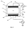
- Fig. 5 shows a plasma operating apparatus with two capacitively coupled plasma sources 500. This is very similar to the plasma apparatus shown in fig. 1 . The difference is that the grounded electrode is now connected to its own RF voltage system 530. This is called the second RF voltage system 530 and the essential difference is that an additional powered electrode has been added to the system.
- the RF voltage system 520 is connected to the powered electrode 508, a substrate or work piece is placed in front of the powered electrode 508. The substrate can also be placed in front of the second powered electrode 512.
- the second powered electrode is connected to the second RF voltage system 530.
- the embodiments of the RF voltage system 520 and the second RF voltage system 530 could be constructed in many different ways.
- the essential element is that at least two harmonic components of the applied RF voltage be even harmonics of each other and that there is a controlled relative phase between the two. This could be accomplished by having both of these harmonic components on RF voltage generator 520 or the second RF voltage 530. It is possible that RF voltage system 520 is operated in a mode where there is no phase locking with the second RF voltage system 530, or they could be operated in a phase locked manner.
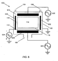
- Fig. 6 shows a plasma operating apparatus with a DC/RF triode source 600. This is very similar to the capacitively coupled plasma source shown in fig. 5 , except the addition of an additional DC electrode 632.
- This electrode 632 is connected to a DC power source 634.
- the RF voltage system 620 is connected to the powered electrode 608 and the second RF generator 630 is connected to the second powered electrode 612.
- the substrate 110 is shown as being placed on the powered electrode 608.
- the substrate could also be placed upon the second powered electrode 612 or even the electrode 632 connected to the DC power source 634.
- the RF voltage system 620 and the second RF voltage system 630 could have a variety of different examples.
- the two phase controlled even harmonics of the applied voltage could be applied entirely through RF voltage system 620 or through RF voltage system 630 or the two RF voltage systems could be operated in a phase locked manner.
- Fig. 7 shows a plasma operating apparatus with an inductively coupled plasma source 700.
- the basic structure of the plasma chamber is identical to previous examples, however the method of coupling power into the plasma and the primary method of generating the plasma is different.
- an RF generator 720 is connected to the powered electrode 708.
- the substrate is placed on the powered electrode 708 and the vacuum chamber wall 102 functions as the second electrode.
- the RF current takes a path from the powered electrode 708 to the vacuum chamber wall 102.
- the second RF voltage system 736 is connected to a coil 738 which is shown as being wrapped around a dielectric tube 740 which is sealed at one end and has the other end open to the vacuum chamber 102.
- the RF power is coupled inductively to the plasma 114.
- the dielectric tube 740 could be replaced with a dome or a flat surface.
- the wafer or substrate could also be placed in the vicinity of the plasma chamber wall 102 to receive the benefit of the invention.
- the purpose of this figure is to show how the invention could be implemented in a radically different type of plasma operating apparatus.
- the advantage of using different types of plasma sources is that you would have different combinations of ion fluxes and ion energies available.
- the embodiment of the RF voltage system 720 could be nearly identical to the RF voltage system 120 shown in fig. 1 . It would also be possible to add additional electrodes to this system.
- Fig. 8 shows an example included in a plasma operating apparatus with an ECR (Electron Cyclotron Resonance) plasma source 800.
- the basic structure of the vacuum chamber is very similar to the previous examples except that the main method of generating the plasma is different.
- the RF voltage system 820 is connected to the powered electrode 808.
- the RF voltage system 820 would be very similar to the RF voltage system 120 shown in fig. 1 .
- the plasma is generated by directing a microwave source 840 towards a dielectric tube 844.
- a magnetic field is formed by coils 842 which are wound around the dielectric tube 844. Again, the dielectric tube is closed at one end and opens into the volume of the vacuum chamber.
- the plasma is generated inside the dielectric tube 844 and streams into the plasma chamber. Again the substrate could be placed adjacent to the vacuum chamber wall 102 instead of being placed upon the powered electrode 108.
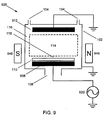
- Fig. 9 shows a plasma operating apparatus with a magnetically enhanced capacitively coupled plasma source 900.
- This example is almost identical to that shown in fig. 1 .
- the difference is that several magnets have been placed in proximity outside of the vacuum chamber wall to the powered electrode 908.
- the purpose of these magnets is that is slows the diffusion of electrons towards the electrode and enhances the plasma density within the vacuum chamber.
- the RF voltage system 920 is connected to the powered electrode 908.
- the substrate is placed upon the powered electrode 908. Again, the substrate or work piece could also be located in front of the grounded electrode 912.
- the ground electrode is connected to the ground.
- the magnets 946 are located outside the chamber wall 102 adjacent to the powered electrode 908. This is another example of how the invention could be applied to a conventional plasma operating apparatus.
- the RF generator 920 would be very similar or the same as the one shown in fig. 1 .
- Plasma operating apparatus with a capacitively coupled plasma source 102 Vacuum chamber wall 104 Gas inlet 106 Vacuum pump outlet 108 Powered electrode 110 Substrate or work object 112 Grounded electrode 114 Plasma 116 Plasma sheath 118 Plasma sheath above the substrate 120 RF voltage system 121 RF voltage generator 122 Phase shifter 123 Frequency doubler 124 RF amplifier 125 RF amplifier 126 Impedance matching network 127 Impedance matching network 128 Low pass filter 129 High pass filter 400 Control system 402 Hardware interface 404 Microprocessor 406 Computer program product 408 User interface 410 Plasma generating system 420 Control unit of RF voltage system 430 Plasma sensor 440 Dialogue box for ion energy and ion flux control 442 Region for selecting operation mode 444 Radio buttons 446 Region for controlling ion energy and ion flux in static mode 448 Text input boxes 450 Region for dynamically controlling the ion energy and ion flux 452 User adjustable controller 454 Input field 500 Plasma operating apparatus with two capacitively coupled plasma sources 508
- Capacitively coupled radio-frequency plasmas are applied to a wide range of different processes in industry, e.g. the manufacturing of semiconductor or the production of large area solar cell panels.
- the discharge is operated between two electrodes where typically the RF voltage is applied to one electrode and the counter electrode is on the same potential as the chamber wall, i.e. on ground.
- the applied voltage is mostly distributed over so called sheaths, the boundary region between the quasi-neutral plasma a and the electrode/wall. Within the sheaths, ions created in the plasma are accelerated towards the electrode. Therefore, the impinging energy is determined by the sheath voltage.
- the high mass of the ions and the related inertia leads to an acceleration than is determined only by the RF period averaged mean voltage across the sheath, the so called RF bias.
- the ion energy is essential for the etching, deposition, or sputtering behavior.
- the temporal oscillation of the sheath voltages leads also to an acceleration and related heating of electrons. Therefore, the production of the plasma is directly related to the frequency and amplitude of the RF voltage oscillation. Higher frequencies and higher voltage amplitudes lead directly to higher electron velocities and more efficient plasma production.
- the RF self-bias is reduced by applying higher R F frequencies.
- the wall area is much larger than the electrode area (asymmetric discharges) or the areas are effectively identical (symmetric discharges).
- the gap between the electrode and the counter electrode which is on ground potential, is much smaller than the electrode radius, which gives the outer edge an ideally negligible influence.
- Symmetric discharges allow a minimum volume which provides better control of plasma chemistry due to more rapid gas exchange times.
- large area applications as e.g. solar cell panels, there are effectively no alternatives to symmetric conditions. While in asymmetric discharges the better part of the applied voltage is distributed across the sheath in front of the smaller electrode, in symmetric discharges also the voltage distribution is symmetric.
- a. novel method is proposed that allows in geometrically symmetric discharges asymmetric sheath voltages and ion energies.
- This asymmetry is realized by applying in parallel two harmonic frequencies with a controlled relative phase, where the higher frequency must be an even multiple of the tower frequency.
- the controlled relative phase could be held fixed.
- the effect is biggest for the combination of a given frequency with its second harmonic and both frequencies having the same amplitude.
- the ratio of the ion energies at both electrodes can be continuously varied by tuning the relative phase between the two frequencies. Thereby the ion energies can be either identical, being much large at one electrode than at the other or vice versa, or having any intermediate value.
- the theoretically maximum possible ratio is about three.
- the asymmetry in the sheaths caused by adding an even harmonic has interesting consequences.
- This asymmetry causes a DC self bias that balances the ion and electron fluxes.
- the DC self bias will naturally adjust its self. This can be changed by adjusting the amplitudes of the individual frequency components, and it can also be accomplished by adjusting the phase between the applied voltages.
- Adjusting the phase is extremely powerful. As the phase is changed, the RMS voltage applied to the discharge stays the same. The plasma parameters will change as the phase changes, but not as drastically as when the amplitudes of the harmonics are changed. As will be shown, the DC self bias on the electrodes will change greatly. This gives one the ability to adjust the ion energy to the electrodes. In fact, one can choose to increase or decrease the ion energy. As the ion energy impacting one electrode is increased the other is decreased. This also means that the roles of the two electrodes can be reversed electrically.
- Embodiments of the invention can be used for a variety of applications. Essentially it will be useful whenever one would like to be able to independently adjust the number and energy of ions striking a substrateexposed to a plasma. Applications include, but are not limited to: etching plasmas (e.g. semiconductors), deposition plasmas (e.g. solar cells) , and plasmas used For surface modifications (e.g. polymer activation).
- etching plasmas e.g. semiconductors
- deposition plasmas e.g. solar cells
- plasmas used For surface modifications e.g. polymer activation
- Fig. 11 shows a diagram of one possible embodiment of the invention using standard RF components. This figure is intended to represent a possible embodiment of the invention using standard RF electronic components. There are many other alternate and modified designs that can achieve the same result and are obvious for experts in the field. Embodiments of the invention are not intended to be limited to this design.
- a single RF frequency function generator is used to create a single RF frequency.
- the RF generator is set to the fundamental frequency desired.
- the RF signal is then split in two. This can also be done using standard RF components.
- One signal is fed into a frequency doubler. This generates the second harmonic.
- the other signal is fed into a phase shifter.
- the phase shifter is used to control the relative phase of the two signals.
- Each of these signals is then fed into its own Ref amplifier.
- Each having its own amplifier, the output amplitude of the fundamental and the second harmonic are independently adjustable.
- a matching network is attached to each. The matching networks adjusts the impedance of the each signal to maximize the power delivered by each to the plasma.
- the high and low frequency RF electronics are isolated from each other using high and low pass filters.
- a major application of embodiments of this invention would be in the processing of large substrate in plasmas.
- An example would be the large dielectric substrates used for manufacturing solar panels. They can be several square meters in surface area.
- An example is the Leybold Optics linear Cluster-System PHOEBUS for production of large scale solar panels.
- the ion energy striking a surface has a large effect during etching processes, and can effect the quality and properties of thin films and surfaces in contact during plasma processing.
- the second technique is to apply two or more RF frequencies.
- Lam Research Exelan high performance dielectricetch system This is a symmetric, capacitively coupled plasma reactor used for etching processes in the semiconductor industry.
- the Lam Exelan applies 2 MHz and 27 MHz RF power to a single electrode. The two frequencies are not phase locked.
- This etching tool would benefit from and could be retrofitted with an embodiment of the invention. This would involve removing the existing RF generators and matching networks and replacing them with a new RF power system. Since embodiments of the invention control the ion energy by a purely electrical means, there would be no need to modify the actually plasma chamber and electrode. The electronics need only be replaced.
- plasma reactors that are generated by other means. Examples would be plasmas produced by inductively coupled antennas or the microwave generation of plasmas. It is also common for these plasmas to have an additional capacitive electrode for the coupling of RF power into the discharge.
- the additional electrode acts as one electrode and the chamber wall acts as the other electrodes. Typically the wall has a much larger surface area than the electrode. This in-equal area will cause a DC self bias to develop which will cause the acceleration of ions towards the substrate resting upon the electrode.
- An embodiment of the invention could also be used to adjust the ion energy striking the surface. As with plasmas generated exclusively by capacitive means, these other plasma chambers could by retrofitted by replacing the RF electronics used for powering the capacitive electrodes.
- An example of a commercial chamber that could be modified is the Applied Materials DPS plasma reactor.
- the plasma is generated using a inductive antenna mounted on a dielectric dome.
- a capacitive electrode is mounted beneath for modifying the ion energy to the substrate.
- the RF electronics for the capacitive bias could be replaced.
- the bulk of the plasma has a impedance that is very small in comparison to the impedance of the sheaths.
- a simple analytical model is developed which assumes a quadratic charge voltage relationship for the sheaths any neglects the impedance of the plasma bulk.
- V AC is considered to be the AC voltage applied to a discharge. The DC self bias builds up naturally and will be considered later in the chapter.
- Each of the two cosine functions are symmetric about the x -axis, but the sum of the two is not. Above the axis there is one maximum per rf cycle, and below the axis there are two minimums per rf cycle. The sheaths on the two electrodes produced by this applied voltage will very clearly not be symmetric. A DC bias will necessarily need to build up to balance the charged particle fluxes to the two electrodes. This is the basis of the effect.
- the phase can be used to control the degree of asymmetry in the sheath and therefore the DC self bias produced by the effect. Additionally, looking at phases ⁇ . 0 and ⁇ .... ⁇ /2 we see that by simply changing the phase angle the roles of the two electrodes can be reversed electrically. The effect not only creates a controllable DC self bias, but it also allows the roles of the two electrodes to be reversed. Ion energies can be increased or decreased. This is in great contract to the conventional DC self bias effect which relies on the geometry of the discharge and is not reversible.
- the fundamental and the second harmonic are always chosen. There will be an asymmetry in the two sheaths whenever an even harmonic in included, but the effect is largest when it is simply the fundamental and the second harmonic.
- the self bias effect will be studied with a simple analytical model that is originally due to Czarnetzki [1].
- This model solves the non-linear electrical equations by using the so-called matrix sheath.
- the ion density is considered to be constant within each sheath and the electron density is a step function.
- the sheath has a quadratic charge-voltage relationship. All of the quantities in the model are dimensionless and normalized.
- the total voltage across the discharge V total
- V total the normalized voltage across the entire discharge
- ⁇ ⁇ + ⁇ ⁇ ⁇
- ⁇ the normalized and dimensionless DC self bias
- ⁇ wt
- ⁇ ( ⁇ ) the normalized and dimensionless AC voltage applied to the discharge.
- ⁇ ( ⁇ ) is the voltage applied by the rf generator.
- Normally capacitively coupled discharges are electrically isolated from the generator by one or more blocking capacitors contained in the matching network. The DC self-bias, ⁇ builds up naturally to balance charged particle fluxes.
- ⁇ se - q 2
- ⁇ sg ⁇ ⁇ q t - q 2
- ⁇ n ⁇ se ⁇ A se 2
- n ⁇ sg ⁇ A sg 2 .
- q is the charge in the powered sheath
- q t is the total charge in both sheaths
- n ⁇ se is the average ion density in the sheath of the powered electrode
- n ⁇ sg is the average ion density in the grounded electrode
- a se is the area of the powered electrode
- a sg is the area of the grounded electrode.
- ⁇ is a factor used to account for differences in the area of the electrode and in the average ion density in the sheath. In a geometrically symmetric discharge both are a identical, but the ion densities can deviate due to asymmetric sheath voltages.
- ⁇ and q t can be solved for in terms of ⁇ m1 and ⁇ m2 .
- Fig. 29 shows a plot of Eq. 29 this shows that ⁇ varies close to lineary.
- the mean ion energy striking an electrode will also varies close to linearly as ⁇ is changed. This would allow very precise control of the ion energies.
- the analytical model can also be used to explicitly calculate the voltages across the individual sheaths.
- the good agreement between the simple analytical model and the simulation is achieved by using the correct value for e as resulting from the simulation.
- this parameter is not calculated self consistently within the analytical model it shows that the physical picture behind the model is correct. Therefore, the asymmetry in the sheath voltages causes also an asymmetry in the sheath densities which then further amplifies the effect of asymmetric sheath voltages. This finally makes the technique even more effective.
- the plasma parameters used for this simulations described in this section were taken from experimental data published by Godyak, Piejak, and Alexandrovich
- the experimental parameters described in this reference for the 20 mTorr case in Fig. 18 were used. Quantities such as the electron temperature and electron density were obtained by digitizing the EEPF (Electron Energy Probability Function) in Fig. 18 and extracting the data. Instead of using a single, sinusoidal frequency, the applied voltage waveform used is Eq. 5. The amplitude of this waveform has been chosen so that its RMS value is equal to the RMS voltage of the original single frequency experiment. The IED at both electrodes was calculated for a variety of different values of ⁇ .
- the sheath model of Brinkmann can also be used for determining the DC self bias.
- the DC self bias, V DC in this case is -221 V.
- the DC self bias predicted by the simple analytical model for a V 0 of 315 V was -137.8 V.
- the electric fields for the ion Monte-Carlo simulation are calculated using the Brinkmann model, and as in Wild and Koidal's original paper only change exchange collisions are considered. Adding elastic collisions between ions and neutral atoms would make the simulation more realistic, but would add substantial computational complexity.
- the present simulation in intended to demonstrates that even in the pretence of collisions this effect is observable and the ability of this effect to adjust ion energies. It can be expected that the effect of elastic collisions would be basically a flattening of the structures in the spectra.
- Fig. 22-A shows the IED at the powered electrode
- Fig. 22-B shows the IED at the grounded electrode
- Figs. 21 and 22 demonstrate the adjustability of the IEDs using the DC self bias effect.
- the Brinkmann model can also be used to calculate charged particle densities in the sheath.
- Fig. 23 shows the time averaged ion densities for the two sheaths that correspond to the two IEDs shown in Fig. 21. Sheath A matches with Fig. 21-A and sheath B matches with Fig. 21-B. These densities are used in the next section to calculated ⁇ for the analytical model.
- the sheath voltage calculated using the analytical model can also be improved using this value of ⁇ .
- the various voltages displayed in Fig. 24 show very good agreement with the numerical simulation.
Landscapes
- Chemical & Material Sciences (AREA)
- Analytical Chemistry (AREA)
- Physics & Mathematics (AREA)
- Engineering & Computer Science (AREA)
- Plasma & Fusion (AREA)
- Drying Of Semiconductors (AREA)
- Plasma Technology (AREA)
- Electron Sources, Ion Sources (AREA)
- Physical Vapour Deposition (AREA)
Claims (12)
- Procédé d'ajustement d'une autopolarisation en courant continu devant des électrodes (102, 106, 108, 112, 508, 512, 608, 612, 632, 708, 808, 908 ou 912) dans un appareil de traitement par plasma (100, 500, 600, 700, 800 ou 900) par application d'une tension RF avec au moins deux composantes de fréquence harmonique ayant une phase relative commandée entre les composantes, au moins l'une des composantes de fréquence supérieure étant établie en tant que multiple paire de la composante de fréquence inférieure, l'autopolarisation en courant continu des gaines entre le plasma et les électrodes étant ajustée de manière linéaire par réglage de la phase relative.
- Procédé selon la revendication 1, dans lequel l'autopolarisation en courant continu est commandée de manière dynamique par variation de la phase relative entre les composantes harmoniques de la tension appliquée et/ou par variation des amplitudes des composantes harmoniques de la tension appliquée.
- Procédé selon l'une des revendications 1 ou 2, dans lequel la phase relative de la composante harmonique de la tension appliquée est fixe.
- Procédé selon l'une des revendications 1 ou 3, dans lequel les amplitudes des composantes harmoniques de la tension appliquée sont fixes.
- Procédé selon l'une quelconque des revendications précédentes, dans lequel les au moins deux composantes de fréquence harmonique ayant une phase relative commandée de la tension RF sont appliquées à une électrode.
- Procédé selon l'une quelconque des revendications précédentes, dans lequel l'une des composantes de fréquence supérieure de la tension appliquée est la seconde harmonique de la fréquence inférieure.
- Procédé selon l'une quelconque des revendications précédentes, dans lequel le rapport des énergies des ions aux électrodes est amené à varier par réglage de la phase relative entre les au moins deux fréquences.
- Procédé selon l'une quelconque des revendications précédentes, dans lequel la phase relative est utilisée pour commander le degré d'asymétrie dans les gaines entre le plasma et les électrodes pour augmenter ou diminuer l'énergie des ions.
- Procédé selon l'une quelconque des revendications 1 à 8, dans lequel le plasma est généré par la tension RF qui établit également l'autopolarisation en courant continu (100, 500, 600 ou 900).
- Procédé selon l'une quelconque des revendications précédentes, dans lequel le plasma est utilisé pour une modification de surface,
pour un dépôt de couches minces, pour une gravure au plasma, pour une gravure au plasma de substrats diélectriques, pour la fabrication de dispositifs à semi-conducteurs, de dispositifs de systèmes microélectromécaniques (MEMS), de panneaux de cellules solaires (photovoltaïques), ou de dispositifs d'affichage de télévision à écran plat, pour la pulvérisation cathodique de surfaces, la modification de surfaces en phase gazeuse, le nettoyage de surfaces, la commande d'énergies de surface, l'amélioration de la biocompatibilité, la promotion de l'adhésion, la fabrication de nanoparticules, l'assemblage de nanoparticules en des structures ou des dispositifs, et/ou la réticulation de surface de polymères. - Procédé selon l'une quelconque des revendications précédentes, dans lequel une asymétrie dans la région de gaine de plasma (116 ou 118) provoque l'autopolarisation en courant continu.
- Procédé selon l'une quelconque des revendications précédentes, dans lequel l'une des au moins deux électrodes est une paroi (112) d'une chambre de vide et/ou une partie d'une pompe à vide (108).
Applications Claiming Priority (3)
| Application Number | Priority Date | Filing Date | Title |
|---|---|---|---|
| US3826308P | 2008-03-20 | 2008-03-20 | |
| PCT/EP2008/059133 WO2009115135A1 (fr) | 2008-03-20 | 2008-07-11 | Procédé de réglage de l'énergie des ions dans des plasmas radiofréquences |
| EP08786101A EP2122657B8 (fr) | 2008-03-20 | 2008-07-11 | Procédé de réglage de l'énergie des ions dans des plasmas radiofréquences |
Related Parent Applications (2)
| Application Number | Title | Priority Date | Filing Date |
|---|---|---|---|
| WOPCT/EP2008/059133 Previously-Filed-Application | 2008-07-11 | ||
| EP08786101.9 Division | 2008-07-11 |
Publications (2)
| Publication Number | Publication Date |
|---|---|
| EP2249372A1 EP2249372A1 (fr) | 2010-11-10 |
| EP2249372B1 true EP2249372B1 (fr) | 2013-01-02 |
Family
ID=39831709
Family Applications (2)
| Application Number | Title | Priority Date | Filing Date |
|---|---|---|---|
| EP10170734A Not-in-force EP2249372B1 (fr) | 2008-03-20 | 2008-07-11 | Procédé de réglage de l'énergie des ions dans des plasmas radiofréquences |
| EP08786101A Active EP2122657B8 (fr) | 2008-03-20 | 2008-07-11 | Procédé de réglage de l'énergie des ions dans des plasmas radiofréquences |
Family Applications After (1)
| Application Number | Title | Priority Date | Filing Date |
|---|---|---|---|
| EP08786101A Active EP2122657B8 (fr) | 2008-03-20 | 2008-07-11 | Procédé de réglage de l'énergie des ions dans des plasmas radiofréquences |
Country Status (7)
| Country | Link |
|---|---|
| US (2) | US8643280B2 (fr) |
| EP (2) | EP2249372B1 (fr) |
| CN (1) | CN101978461B (fr) |
| AT (1) | ATE504076T1 (fr) |
| DE (1) | DE602008005858D1 (fr) |
| TW (1) | TW200952560A (fr) |
| WO (1) | WO2009115135A1 (fr) |
Families Citing this family (68)
| Publication number | Priority date | Publication date | Assignee | Title |
|---|---|---|---|---|
| WO2009115135A1 (fr) | 2008-03-20 | 2009-09-24 | RUHR-UNIVERSITäT BOCHUM | Procédé de réglage de l'énergie des ions dans des plasmas radiofréquences |
| DE102009020436A1 (de) * | 2008-11-04 | 2010-09-16 | Fraunhofer-Gesellschaft zur Förderung der angewandten Forschung e.V. | Verfahren und Vorrichtung zur Plasmabehandlung eines flachen Substrats |
| US9767988B2 (en) | 2010-08-29 | 2017-09-19 | Advanced Energy Industries, Inc. | Method of controlling the switched mode ion energy distribution system |
| US11615941B2 (en) | 2009-05-01 | 2023-03-28 | Advanced Energy Industries, Inc. | System, method, and apparatus for controlling ion energy distribution in plasma processing systems |
| EP2407998B1 (fr) | 2010-07-15 | 2019-02-13 | Ecole Polytechnique | Traitement plasma pour réacteur à capacité couplée avec excitation trapézoïdale en forme d'onde |
| US9117767B2 (en) * | 2011-07-21 | 2015-08-25 | Lam Research Corporation | Negative ion control for dielectric etch |
| US9184028B2 (en) | 2010-08-04 | 2015-11-10 | Lam Research Corporation | Dual plasma volume processing apparatus for neutral/ion flux control |
| US9793126B2 (en) | 2010-08-04 | 2017-10-17 | Lam Research Corporation | Ion to neutral control for wafer processing with dual plasma source reactor |
| US8869742B2 (en) | 2010-08-04 | 2014-10-28 | Lam Research Corporation | Plasma processing chamber with dual axial gas injection and exhaust |
| CN102686004B (zh) * | 2011-03-17 | 2015-05-13 | 中微半导体设备(上海)有限公司 | 用于等离子体发生器的可控制谐波的射频系统 |
| WO2012156062A1 (fr) * | 2011-05-13 | 2012-11-22 | Leybold Optics Gmbh | Procédé de traitement au plasma d'un substrat dans un dispositif à plasma |
| US20130122711A1 (en) * | 2011-11-10 | 2013-05-16 | Alexei Marakhtanov | System, method and apparatus for plasma sheath voltage control |
| JP6377060B2 (ja) * | 2012-08-28 | 2018-08-22 | アドバンスト・エナジー・インダストリーズ・インコーポレイテッドAdvanced Energy Industries, Inc. | 広ダイナミックレンジイオンエネルギーバイアス制御、高速イオンエネルギー切り替え、イオンエネルギー制御およびパルスバイアス供給部、および仮想フロントパネル |
| US9685297B2 (en) | 2012-08-28 | 2017-06-20 | Advanced Energy Industries, Inc. | Systems and methods for monitoring faults, anomalies, and other characteristics of a switched mode ion energy distribution system |
| JP6207880B2 (ja) * | 2012-09-26 | 2017-10-04 | 東芝メモリ株式会社 | プラズマ処理装置およびプラズマ処理方法 |
| US9245761B2 (en) | 2013-04-05 | 2016-01-26 | Lam Research Corporation | Internal plasma grid for semiconductor fabrication |
| DE102014105445A1 (de) * | 2013-04-26 | 2014-10-30 | Mks Instruments Inc. | Frequenz- und Phasensteuerung einer Multi-Radiofrequenz-Leistungsversorgung |
| US9336995B2 (en) | 2013-04-26 | 2016-05-10 | Mks Instruments, Inc. | Multiple radio frequency power supply control of frequency and phase |
| US9460894B2 (en) | 2013-06-28 | 2016-10-04 | Lam Research Corporation | Controlling ion energy within a plasma chamber |
| US9147581B2 (en) | 2013-07-11 | 2015-09-29 | Lam Research Corporation | Dual chamber plasma etcher with ion accelerator |
| US20150107618A1 (en) * | 2013-10-21 | 2015-04-23 | Applied Materials, Inc. | Oxygen containing plasma cleaning to remove contamination from electronic device components |
| WO2015069428A1 (fr) * | 2013-11-06 | 2015-05-14 | Applied Materials, Inc. | Appareil de suppression de génération de particules par modulation de la composante continue |
| FR3020718B1 (fr) | 2014-05-02 | 2016-06-03 | Ecole Polytech | Procede et systeme pour controler des flux d'ions dans un plasma rf. |
| US9026407B1 (en) | 2014-10-16 | 2015-05-05 | Christine Marie Kennefick | Method of making and using a material model of elements with planar faces |
| US9595424B2 (en) * | 2015-03-02 | 2017-03-14 | Lam Research Corporation | Impedance matching circuit for operation with a kilohertz RF generator and a megahertz RF generator to control plasma processes |
| KR20170024922A (ko) * | 2015-08-26 | 2017-03-08 | 삼성전자주식회사 | 플라즈마 발생 장치 |
| US10395895B2 (en) * | 2015-08-27 | 2019-08-27 | Mks Instruments, Inc. | Feedback control by RF waveform tailoring for ion energy distribution |
| US10008366B2 (en) | 2015-09-08 | 2018-06-26 | Applied Materials, Inc. | Seasoning process for establishing a stable process and extending chamber uptime for semiconductor chip processing |
| US9644271B1 (en) * | 2016-05-13 | 2017-05-09 | Lam Research Corporation | Systems and methods for using electrical asymmetry effect to control plasma process space in semiconductor fabrication |
| US9852889B1 (en) | 2016-06-22 | 2017-12-26 | Lam Research Corporation | Systems and methods for controlling directionality of ions in an edge region by using an electrode within a coupling ring |
| US10026592B2 (en) * | 2016-07-01 | 2018-07-17 | Lam Research Corporation | Systems and methods for tailoring ion energy distribution function by odd harmonic mixing |
| JP6643212B2 (ja) * | 2016-09-16 | 2020-02-12 | 株式会社日立ハイテクノロジーズ | プラズマ処理装置及びプラズマ処理方法 |
| EP3309815B1 (fr) * | 2016-10-12 | 2019-03-20 | Meyer Burger (Germany) AG | Dispositif de traitement au plasma comprenant deux sources de plasma excitées par micro-ondes couplées ensemble et procédé de fonctionnement d'un tel dispositif de traitement au plasma |
| US9812295B1 (en) | 2016-11-15 | 2017-11-07 | Lyten, Inc. | Microwave chemical processing |
| US9997334B1 (en) | 2017-02-09 | 2018-06-12 | Lyten, Inc. | Seedless particles with carbon allotropes |
| US9767992B1 (en) | 2017-02-09 | 2017-09-19 | Lyten, Inc. | Microwave chemical processing reactor |
| JP7042282B2 (ja) | 2017-03-16 | 2022-03-25 | ライテン・インコーポレイテッド | 炭素及びエラストマーの融合 |
| US10920035B2 (en) | 2017-03-16 | 2021-02-16 | Lyten, Inc. | Tuning deformation hysteresis in tires using graphene |
| JP7018288B2 (ja) * | 2017-10-10 | 2022-02-10 | 東京エレクトロン株式会社 | 成膜方法 |
| US10777386B2 (en) * | 2017-10-17 | 2020-09-15 | Lam Research Corporation | Methods for controlling plasma glow discharge in a plasma chamber |
| WO2019099937A1 (fr) | 2017-11-17 | 2019-05-23 | Advanced Energy Industries, Inc. | Application améliorée de charges de modulation dans un système de traitement au plasma |
| TWI744566B (zh) * | 2017-11-17 | 2021-11-01 | 新加坡商Aes全球公司 | 用於在空間域和時間域上控制基板上的電漿處理之系統和方法,及相關的電腦可讀取媒體 |
| TWI726258B (zh) | 2017-11-17 | 2021-05-01 | 新加坡商Aes全球公司 | 用於電漿處理之方法和系統以及相關的非暫時性電腦可讀取媒體 |
| WO2019126196A1 (fr) | 2017-12-22 | 2019-06-27 | Lyten, Inc. | Matériaux composites structurés |
| EP3735582A4 (fr) * | 2018-01-04 | 2021-11-10 | Lyten, Inc. | Capteur de gaz résonnant |
| WO2019143559A1 (fr) | 2018-01-16 | 2019-07-25 | Lyten, Inc. | Barrière de pression transparente aux micro-ondes |
| US10304669B1 (en) * | 2018-01-21 | 2019-05-28 | Mks Instruments, Inc. | Adaptive counter measure control thwarting IMD jamming impairments for RF plasma systems |
| TWI758589B (zh) * | 2018-03-01 | 2022-03-21 | 美商應用材料股份有限公司 | 電漿源組件和提供電漿的方法 |
| KR102370012B1 (ko) * | 2018-04-04 | 2022-03-04 | 어플라이드 머티어리얼스, 인코포레이티드 | 바이어스 동작에 대한 rf 맞춤조정된 전압 |
| US20190311884A1 (en) * | 2018-04-04 | 2019-10-10 | Applied Materials, Inc. | Rf tailored voltage on bias operation |
| US20190318913A1 (en) * | 2018-04-13 | 2019-10-17 | Tokyo Electron Limited | Apparatus and Method for Controlling Ion Energy Distribution in Process Plasmas |
| KR20200133274A (ko) * | 2018-04-13 | 2020-11-26 | 도쿄엘렉트론가부시키가이샤 | 공정 플라즈마의 이온 에너지 분포를 제어하기 위한 장치 및 방법 |
| US10998170B2 (en) * | 2018-04-13 | 2021-05-04 | Tokyo Electron Limited | Method for ion mass separation and ion energy control in process plasmas |
| US10916409B2 (en) * | 2018-06-18 | 2021-02-09 | Lam Research Corporation | Active control of radial etch uniformity |
| CN111092008A (zh) * | 2018-10-24 | 2020-05-01 | 江苏鲁汶仪器有限公司 | 一种感应耦合等离子体刻蚀设备及刻蚀方法 |
| KR20220031713A (ko) | 2019-07-12 | 2022-03-11 | 에이이에스 글로벌 홀딩스 피티이 리미티드 | 단일 제어식 스위치를 갖는 바이어스 공급부 |
| CN110310878B (zh) | 2019-08-28 | 2019-11-12 | 中微半导体设备(上海)股份有限公司 | 一种等离子体处理器及其处理方法 |
| JP7262375B2 (ja) * | 2019-11-26 | 2023-04-21 | 東京エレクトロン株式会社 | プラズマ処理方法及びプラズマ処理装置 |
| CN113035677B (zh) * | 2019-12-09 | 2023-01-24 | 中微半导体设备(上海)股份有限公司 | 等离子体处理设备以及等离子体处理方法 |
| SE544676C2 (en) * | 2020-04-06 | 2022-10-11 | Ionautics Ab | Method for monitoring process conditions of, and method for controlling, a plasma pvd process |
| CN112259434A (zh) * | 2020-11-04 | 2021-01-22 | 大连理工大学 | 一种任意波形驱动放电控制系统 |
| JP2024527822A (ja) * | 2021-07-22 | 2024-07-26 | ラム リサーチ コーポレーション | プラズマプロセスの監視および制御 |
| CN113652674A (zh) * | 2021-09-07 | 2021-11-16 | 佛山市思博睿科技有限公司 | 一种基于磁约束等离子体超双疏膜层的制备装置及方法 |
| US12106925B2 (en) * | 2021-12-23 | 2024-10-01 | Applied Materials, Inc. | Cyclotron having continuously variable energy output |
| US11942309B2 (en) | 2022-01-26 | 2024-03-26 | Advanced Energy Industries, Inc. | Bias supply with resonant switching |
| US11670487B1 (en) | 2022-01-26 | 2023-06-06 | Advanced Energy Industries, Inc. | Bias supply control and data processing |
| US12046448B2 (en) | 2022-01-26 | 2024-07-23 | Advanced Energy Industries, Inc. | Active switch on time control for bias supply |
| US11978613B2 (en) | 2022-09-01 | 2024-05-07 | Advanced Energy Industries, Inc. | Transition control in a bias supply |
Family Cites Families (12)
| Publication number | Priority date | Publication date | Assignee | Title |
|---|---|---|---|---|
| US5325019A (en) * | 1992-08-21 | 1994-06-28 | Sematech, Inc. | Control of plasma process by use of harmonic frequency components of voltage and current |
| KR100560886B1 (ko) * | 1997-09-17 | 2006-03-13 | 동경 엘렉트론 주식회사 | 가스 플라즈마 프로세스를 감시 및 제어하기 위한 시스템및 방법 |
| DE60023964T2 (de) * | 1999-02-01 | 2006-06-22 | Ohmi, Tadahiro, Sendai | Laservorrichtung, Belichtungsapparat unter Verwendung derselben und Herstellungsverfahren |
| US20030079983A1 (en) * | 2000-02-25 | 2003-05-01 | Maolin Long | Multi-zone RF electrode for field/plasma uniformity control in capacitive plasma sources |
| WO2002054835A2 (fr) * | 2001-01-08 | 2002-07-11 | Tokyo Electron Limited | Addition de puissance a des harmoniques choisies de la frequence d'excitation d'un dispositif de traitement au plasma |
| JP4877884B2 (ja) * | 2001-01-25 | 2012-02-15 | 東京エレクトロン株式会社 | プラズマ処理装置 |
| US6841943B2 (en) * | 2002-06-27 | 2005-01-11 | Lam Research Corp. | Plasma processor with electrode simultaneously responsive to plural frequencies |
| JP4773079B2 (ja) * | 2004-11-26 | 2011-09-14 | 株式会社日立ハイテクノロジーズ | プラズマ処理装置の制御方法 |
| JP4804824B2 (ja) * | 2005-07-27 | 2011-11-02 | 株式会社日立ハイテクノロジーズ | プラズマ処理装置 |
| KR100777151B1 (ko) * | 2006-03-21 | 2007-11-16 | 주식회사 디엠에스 | 하이브리드형 플라즈마 반응장치 |
| US7645357B2 (en) * | 2006-04-24 | 2010-01-12 | Applied Materials, Inc. | Plasma reactor apparatus with a VHF capacitively coupled plasma source of variable frequency |
| WO2009115135A1 (fr) | 2008-03-20 | 2009-09-24 | RUHR-UNIVERSITäT BOCHUM | Procédé de réglage de l'énergie des ions dans des plasmas radiofréquences |
-
2008
- 2008-07-11 WO PCT/EP2008/059133 patent/WO2009115135A1/fr active Application Filing
- 2008-07-11 AT AT08786101T patent/ATE504076T1/de active
- 2008-07-11 CN CN200880128271.8A patent/CN101978461B/zh not_active Expired - Fee Related
- 2008-07-11 US US12/864,123 patent/US8643280B2/en not_active Expired - Fee Related
- 2008-07-11 EP EP10170734A patent/EP2249372B1/fr not_active Not-in-force
- 2008-07-11 DE DE602008005858T patent/DE602008005858D1/de active Active
- 2008-07-11 EP EP08786101A patent/EP2122657B8/fr active Active
-
2009
- 2009-02-20 TW TW098105368A patent/TW200952560A/zh unknown
-
2013
- 2013-11-08 US US14/075,026 patent/US8933629B2/en not_active Expired - Fee Related
Also Published As
| Publication number | Publication date |
|---|---|
| US20110248634A1 (en) | 2011-10-13 |
| EP2122657A1 (fr) | 2009-11-25 |
| EP2122657B1 (fr) | 2011-03-30 |
| WO2009115135A1 (fr) | 2009-09-24 |
| ATE504076T1 (de) | 2011-04-15 |
| EP2122657B8 (fr) | 2011-06-22 |
| CN101978461B (zh) | 2013-09-11 |
| EP2249372A1 (fr) | 2010-11-10 |
| DE602008005858D1 (de) | 2011-05-12 |
| CN101978461A (zh) | 2011-02-16 |
| US20140103808A1 (en) | 2014-04-17 |
| TW200952560A (en) | 2009-12-16 |
| US8933629B2 (en) | 2015-01-13 |
| US8643280B2 (en) | 2014-02-04 |
Similar Documents
| Publication | Publication Date | Title |
|---|---|---|
| EP2249372B1 (fr) | Procédé de réglage de l'énergie des ions dans des plasmas radiofréquences | |
| Heil et al. | On the possibility of making a geometrically symmetric RF-CCP discharge electrically asymmetric | |
| Delattre et al. | Radio-frequency capacitively coupled plasmas excited by tailored voltage waveforms: comparison of experiment and particle-in-cell simulations | |
| Czarnetzki et al. | The electrical asymmetry effect in capacitively coupled radio-frequency discharges | |
| Schulze et al. | The electrical asymmetry effect in capacitively coupled radio frequency discharges–measurements of dc self bias, ion energy and ion flux | |
| Donkó et al. | PIC simulations of the separate control of ion flux and energy in CCRF discharges via the electrical asymmetry effect | |
| Zhang et al. | Control of ion energy distributions using phase shifting in multi-frequency capacitively coupled plasmas | |
| Schüngel et al. | Control of plasma properties in capacitively coupled oxygen discharges via the electrical asymmetry effect | |
| Economou | Tailored ion energy distributions on plasma electrodes | |
| Franek et al. | Power supply and impedance matching to drive technological radio-frequency plasmas with customized voltage waveforms | |
| Semmler et al. | Heating of a dual frequency capacitively coupled plasma via the plasma series resonance | |
| EP0721514A1 (fr) | Generateur de plasma a capacites multiples aux performances ameliorees par un champ magnetique et procede associe | |
| Rakhimova et al. | Experimental and theoretical study of ion energy distribution function in single and dual frequency RF discharges | |
| Sun et al. | The effects of electron surface interactions in geometrically symmetric capacitive RF plasmas in the presence of different electrode surface materials | |
| Wang et al. | Ion energy distribution functions in a dual-frequency low-pressure capacitively-coupled plasma: experiments and particle-in-cell simulation | |
| Brandt et al. | Control of charged particle dynamics in capacitively coupled plasmas driven by tailored voltage waveforms in mixtures of Ar and CF4 | |
| Liu et al. | Fundamental study towards a better understanding of low pressure radio-frequency plasmas for industrial applications | |
| CN101128083B (zh) | 等离子体生成装置、等离子体控制方法和基板制造方法 | |
| Harvey et al. | Mode transition in an oxygen low-pressure, very high frequency (162 MHz), multi-tile electrode capacitively coupled plasma | |
| Krüger et al. | Voltage waveform tailoring for high aspect ratio plasma etching of SiO2 using Ar/CF4/O2 mixtures: Consequences of ion and electron distributions on etch profiles | |
| Li et al. | Experimental investigation of ion energy distributions in a dual frequency capacitively coupled Ar/CF4 plasma | |
| JPH08255782A (ja) | プラズマ表面処理装置 | |
| Zhang et al. | Modeling of plasma density, argon ion energy and ion velocity functions in a dipolar electron cyclotron resonance plasma source | |
| Chen | Radiofrequency plasma sources for semiconductor processing | |
| Hong et al. | Electron energy probability function measurement in a 2 MHz and 13.56 MHz dual-frequency capacitively coupled argon plasma |
Legal Events
| Date | Code | Title | Description |
|---|---|---|---|
| PUAI | Public reference made under article 153(3) epc to a published international application that has entered the european phase |
Free format text: ORIGINAL CODE: 0009012 |
|
| AC | Divisional application: reference to earlier application |
Ref document number: 2122657 Country of ref document: EP Kind code of ref document: P |
|
| AK | Designated contracting states |
Kind code of ref document: A1 Designated state(s): AT BE BG CH CY CZ DE DK EE ES FI FR GB GR HR HU IE IS IT LI LT LU LV MC MT NL NO PL PT RO SE SI SK TR |
|
| RIN1 | Information on inventor provided before grant (corrected) |
Inventor name: BRINKMANN, RALF-PETER Inventor name: CZARNETZKI, UWE Inventor name: HEIL, BRIAN GEORGE Inventor name: MUSSENBROCK, THOMAS |
|
| 17P | Request for examination filed |
Effective date: 20110124 |
|
| 17Q | First examination report despatched |
Effective date: 20110811 |
|
| GRAP | Despatch of communication of intention to grant a patent |
Free format text: ORIGINAL CODE: EPIDOSNIGR1 |
|
| GRAS | Grant fee paid |
Free format text: ORIGINAL CODE: EPIDOSNIGR3 |
|
| GRAA | (expected) grant |
Free format text: ORIGINAL CODE: 0009210 |
|
| AC | Divisional application: reference to earlier application |
Ref document number: 2122657 Country of ref document: EP Kind code of ref document: P |
|
| AK | Designated contracting states |
Kind code of ref document: B1 Designated state(s): AT BE BG CH CY CZ DE DK EE ES FI FR GB GR HR HU IE IS IT LI LT LU LV MC MT NL NO PL PT RO SE SI SK TR |
|
| REG | Reference to a national code |
Ref country code: GB Ref legal event code: FG4D |
|
| REG | Reference to a national code |
Ref country code: AT Ref legal event code: REF Ref document number: 592019 Country of ref document: AT Kind code of ref document: T Effective date: 20130115 Ref country code: CH Ref legal event code: EP |
|
| REG | Reference to a national code |
Ref country code: IE Ref legal event code: FG4D |
|
| REG | Reference to a national code |
Ref country code: DE Ref legal event code: R096 Ref document number: 602008021457 Country of ref document: DE Effective date: 20130228 |
|
| REG | Reference to a national code |
Ref country code: AT Ref legal event code: MK05 Ref document number: 592019 Country of ref document: AT Kind code of ref document: T Effective date: 20130102 |
|
| REG | Reference to a national code |
Ref country code: NL Ref legal event code: VDEP Effective date: 20130102 |
|
| PG25 | Lapsed in a contracting state [announced via postgrant information from national office to epo] |
Ref country code: SI Free format text: LAPSE BECAUSE OF FAILURE TO SUBMIT A TRANSLATION OF THE DESCRIPTION OR TO PAY THE FEE WITHIN THE PRESCRIBED TIME-LIMIT Effective date: 20130102 |
|
| REG | Reference to a national code |
Ref country code: LT Ref legal event code: MG4D |
|
| PG25 | Lapsed in a contracting state [announced via postgrant information from national office to epo] |
Ref country code: IS Free format text: LAPSE BECAUSE OF FAILURE TO SUBMIT A TRANSLATION OF THE DESCRIPTION OR TO PAY THE FEE WITHIN THE PRESCRIBED TIME-LIMIT Effective date: 20130502 Ref country code: AT Free format text: LAPSE BECAUSE OF FAILURE TO SUBMIT A TRANSLATION OF THE DESCRIPTION OR TO PAY THE FEE WITHIN THE PRESCRIBED TIME-LIMIT Effective date: 20130102 Ref country code: ES Free format text: LAPSE BECAUSE OF FAILURE TO SUBMIT A TRANSLATION OF THE DESCRIPTION OR TO PAY THE FEE WITHIN THE PRESCRIBED TIME-LIMIT Effective date: 20130413 Ref country code: BG Free format text: LAPSE BECAUSE OF FAILURE TO SUBMIT A TRANSLATION OF THE DESCRIPTION OR TO PAY THE FEE WITHIN THE PRESCRIBED TIME-LIMIT Effective date: 20130402 Ref country code: SE Free format text: LAPSE BECAUSE OF FAILURE TO SUBMIT A TRANSLATION OF THE DESCRIPTION OR TO PAY THE FEE WITHIN THE PRESCRIBED TIME-LIMIT Effective date: 20130102 Ref country code: BE Free format text: LAPSE BECAUSE OF FAILURE TO SUBMIT A TRANSLATION OF THE DESCRIPTION OR TO PAY THE FEE WITHIN THE PRESCRIBED TIME-LIMIT Effective date: 20130102 Ref country code: LT Free format text: LAPSE BECAUSE OF FAILURE TO SUBMIT A TRANSLATION OF THE DESCRIPTION OR TO PAY THE FEE WITHIN THE PRESCRIBED TIME-LIMIT Effective date: 20130102 Ref country code: CZ Free format text: LAPSE BECAUSE OF FAILURE TO SUBMIT A TRANSLATION OF THE DESCRIPTION OR TO PAY THE FEE WITHIN THE PRESCRIBED TIME-LIMIT Effective date: 20130102 Ref country code: NO Free format text: LAPSE BECAUSE OF FAILURE TO SUBMIT A TRANSLATION OF THE DESCRIPTION OR TO PAY THE FEE WITHIN THE PRESCRIBED TIME-LIMIT Effective date: 20130402 |
|
| PG25 | Lapsed in a contracting state [announced via postgrant information from national office to epo] |
Ref country code: FI Free format text: LAPSE BECAUSE OF FAILURE TO SUBMIT A TRANSLATION OF THE DESCRIPTION OR TO PAY THE FEE WITHIN THE PRESCRIBED TIME-LIMIT Effective date: 20130102 Ref country code: PL Free format text: LAPSE BECAUSE OF FAILURE TO SUBMIT A TRANSLATION OF THE DESCRIPTION OR TO PAY THE FEE WITHIN THE PRESCRIBED TIME-LIMIT Effective date: 20130102 Ref country code: NL Free format text: LAPSE BECAUSE OF FAILURE TO SUBMIT A TRANSLATION OF THE DESCRIPTION OR TO PAY THE FEE WITHIN THE PRESCRIBED TIME-LIMIT Effective date: 20130102 Ref country code: LV Free format text: LAPSE BECAUSE OF FAILURE TO SUBMIT A TRANSLATION OF THE DESCRIPTION OR TO PAY THE FEE WITHIN THE PRESCRIBED TIME-LIMIT Effective date: 20130102 Ref country code: GR Free format text: LAPSE BECAUSE OF FAILURE TO SUBMIT A TRANSLATION OF THE DESCRIPTION OR TO PAY THE FEE WITHIN THE PRESCRIBED TIME-LIMIT Effective date: 20130403 Ref country code: PT Free format text: LAPSE BECAUSE OF FAILURE TO SUBMIT A TRANSLATION OF THE DESCRIPTION OR TO PAY THE FEE WITHIN THE PRESCRIBED TIME-LIMIT Effective date: 20130502 |
|
| PG25 | Lapsed in a contracting state [announced via postgrant information from national office to epo] |
Ref country code: HR Free format text: LAPSE BECAUSE OF FAILURE TO SUBMIT A TRANSLATION OF THE DESCRIPTION OR TO PAY THE FEE WITHIN THE PRESCRIBED TIME-LIMIT Effective date: 20130102 |
|
| PG25 | Lapsed in a contracting state [announced via postgrant information from national office to epo] |
Ref country code: DK Free format text: LAPSE BECAUSE OF FAILURE TO SUBMIT A TRANSLATION OF THE DESCRIPTION OR TO PAY THE FEE WITHIN THE PRESCRIBED TIME-LIMIT Effective date: 20130102 Ref country code: EE Free format text: LAPSE BECAUSE OF FAILURE TO SUBMIT A TRANSLATION OF THE DESCRIPTION OR TO PAY THE FEE WITHIN THE PRESCRIBED TIME-LIMIT Effective date: 20130102 Ref country code: RO Free format text: LAPSE BECAUSE OF FAILURE TO SUBMIT A TRANSLATION OF THE DESCRIPTION OR TO PAY THE FEE WITHIN THE PRESCRIBED TIME-LIMIT Effective date: 20130102 Ref country code: SK Free format text: LAPSE BECAUSE OF FAILURE TO SUBMIT A TRANSLATION OF THE DESCRIPTION OR TO PAY THE FEE WITHIN THE PRESCRIBED TIME-LIMIT Effective date: 20130102 |
|
| PLBE | No opposition filed within time limit |
Free format text: ORIGINAL CODE: 0009261 |
|
| STAA | Information on the status of an ep patent application or granted ep patent |
Free format text: STATUS: NO OPPOSITION FILED WITHIN TIME LIMIT |
|
| PG25 | Lapsed in a contracting state [announced via postgrant information from national office to epo] |
Ref country code: CY Free format text: LAPSE BECAUSE OF FAILURE TO SUBMIT A TRANSLATION OF THE DESCRIPTION OR TO PAY THE FEE WITHIN THE PRESCRIBED TIME-LIMIT Effective date: 20130102 |
|
| 26N | No opposition filed |
Effective date: 20131003 |
|
| PG25 | Lapsed in a contracting state [announced via postgrant information from national office to epo] |
Ref country code: IT Free format text: LAPSE BECAUSE OF FAILURE TO SUBMIT A TRANSLATION OF THE DESCRIPTION OR TO PAY THE FEE WITHIN THE PRESCRIBED TIME-LIMIT Effective date: 20130102 |
|
| REG | Reference to a national code |
Ref country code: DE Ref legal event code: R097 Ref document number: 602008021457 Country of ref document: DE Effective date: 20131003 |
|
| PG25 | Lapsed in a contracting state [announced via postgrant information from national office to epo] |
Ref country code: MC Free format text: LAPSE BECAUSE OF FAILURE TO SUBMIT A TRANSLATION OF THE DESCRIPTION OR TO PAY THE FEE WITHIN THE PRESCRIBED TIME-LIMIT Effective date: 20130102 |
|
| REG | Reference to a national code |
Ref country code: IE Ref legal event code: MM4A |
|
| PG25 | Lapsed in a contracting state [announced via postgrant information from national office to epo] |
Ref country code: IE Free format text: LAPSE BECAUSE OF NON-PAYMENT OF DUE FEES Effective date: 20130711 |
|
| PGFP | Annual fee paid to national office [announced via postgrant information from national office to epo] |
Ref country code: CH Payment date: 20140721 Year of fee payment: 7 |
|
| PGFP | Annual fee paid to national office [announced via postgrant information from national office to epo] |
Ref country code: FR Payment date: 20140721 Year of fee payment: 7 Ref country code: GB Payment date: 20140721 Year of fee payment: 7 |
|
| PG25 | Lapsed in a contracting state [announced via postgrant information from national office to epo] |
Ref country code: MT Free format text: LAPSE BECAUSE OF FAILURE TO SUBMIT A TRANSLATION OF THE DESCRIPTION OR TO PAY THE FEE WITHIN THE PRESCRIBED TIME-LIMIT Effective date: 20130102 Ref country code: TR Free format text: LAPSE BECAUSE OF FAILURE TO SUBMIT A TRANSLATION OF THE DESCRIPTION OR TO PAY THE FEE WITHIN THE PRESCRIBED TIME-LIMIT Effective date: 20130102 |
|
| PG25 | Lapsed in a contracting state [announced via postgrant information from national office to epo] |
Ref country code: HU Free format text: LAPSE BECAUSE OF FAILURE TO SUBMIT A TRANSLATION OF THE DESCRIPTION OR TO PAY THE FEE WITHIN THE PRESCRIBED TIME-LIMIT; INVALID AB INITIO Effective date: 20080711 Ref country code: LU Free format text: LAPSE BECAUSE OF NON-PAYMENT OF DUE FEES Effective date: 20130711 |
|
| REG | Reference to a national code |
Ref country code: CH Ref legal event code: PL |
|
| GBPC | Gb: european patent ceased through non-payment of renewal fee |
Effective date: 20150711 |
|
| PG25 | Lapsed in a contracting state [announced via postgrant information from national office to epo] |
Ref country code: CH Free format text: LAPSE BECAUSE OF NON-PAYMENT OF DUE FEES Effective date: 20150731 Ref country code: LI Free format text: LAPSE BECAUSE OF NON-PAYMENT OF DUE FEES Effective date: 20150731 Ref country code: GB Free format text: LAPSE BECAUSE OF NON-PAYMENT OF DUE FEES Effective date: 20150711 |
|
| REG | Reference to a national code |
Ref country code: FR Ref legal event code: ST Effective date: 20160331 |
|
| PG25 | Lapsed in a contracting state [announced via postgrant information from national office to epo] |
Ref country code: FR Free format text: LAPSE BECAUSE OF NON-PAYMENT OF DUE FEES Effective date: 20150731 |
|
| PGFP | Annual fee paid to national office [announced via postgrant information from national office to epo] |
Ref country code: DE Payment date: 20180723 Year of fee payment: 11 |
|
| REG | Reference to a national code |
Ref country code: DE Ref legal event code: R119 Ref document number: 602008021457 Country of ref document: DE |
|
| PG25 | Lapsed in a contracting state [announced via postgrant information from national office to epo] |
Ref country code: DE Free format text: LAPSE BECAUSE OF NON-PAYMENT OF DUE FEES Effective date: 20200201 |