EP2248995A2 - Klemmverbindung - Google Patents
Klemmverbindung Download PDFInfo
- Publication number
- EP2248995A2 EP2248995A2 EP10004197A EP10004197A EP2248995A2 EP 2248995 A2 EP2248995 A2 EP 2248995A2 EP 10004197 A EP10004197 A EP 10004197A EP 10004197 A EP10004197 A EP 10004197A EP 2248995 A2 EP2248995 A2 EP 2248995A2
- Authority
- EP
- European Patent Office
- Prior art keywords
- flap
- einhängeflanschen
- ears
- longitudinal section
- clamping connection
- Prior art date
- Legal status (The legal status is an assumption and is not a legal conclusion. Google has not performed a legal analysis and makes no representation as to the accuracy of the status listed.)
- Granted
Links
Images


Classifications
-
- E—FIXED CONSTRUCTIONS
- E21—EARTH OR ROCK DRILLING; MINING
- E21D—SHAFTS; TUNNELS; GALLERIES; LARGE UNDERGROUND CHAMBERS
- E21D11/00—Lining tunnels, galleries or other underground cavities, e.g. large underground chambers; Linings therefor; Making such linings in situ, e.g. by assembling
- E21D11/14—Lining predominantly with metal
- E21D11/18—Arch members ; Network made of arch members ; Ring elements; Polygon elements; Polygon elements inside arches
- E21D11/22—Clamps or other yieldable means for interconnecting adjacent arch members either rigidly, or allowing arch member parts to slide when subjected to excessive pressure
Definitions
- the invention relates to a clamping connection for overlapping nested U-shaped, lateral ears having profile segments of the yielding underground construction according to the features in the preamble of claim 1.
- Such a resilient underground construction with U-shaped profile segments is within the scope of DE 41 04 798 A1 known.
- the profile segments each have two curved legs, a web connecting the legs and two arranged at the ends remote from the web of the legs, sideways directed flanges, which are also called ears because of their shape. In the overlapping region of two successive profile segments, these are nested, wherein the ears of the encompassing profile segment are supported in the grooves of the inset profile segment, which are formed there on the ears.
- the clamping of the profile segments in the overlapping area is carried out by means of at least two clamping connections, each clamping connection composed of a top flap with lateral straight Ein rehabilitationflanschen, a bottom flap with lateral straight clamping flanges and recesses in the Ein psychologyflanschen and clamping flanges by passing bolts and nuts on the screw rotatable nuts.
- bottom flap is largely U-shaped and adjacent to the side clamping flanges legs and a leg connecting web, wherein in the transition region of the clamping flanges on the legs Stitzwulste are provided, which are supported in throats of the ears of the encompassing profile segment, there is the top flap from a middle longitudinal section with a retracted straight central region as well as at this longitudinal section end subsequent straight Ein rehabilitationflanschen.
- the bolts are inserted with their correspondingly adapted heads in these Ein rehabilitationflansche and enforce their shanks recesses in the Ein distrlanschen and in the clamping flanges of the bottom flap.
- the top flap should be effective as a carrier supported on two supports, which is deformed under the influence of the screw forces.
- the operational deformation of the carrier as a tab can be followed by the change in shape of the neutral thread.
- the frictional resistance between the overlapping nested profile segments is partially generated via defined and partially over-defined pressure surfaces from the normal force of the bolts.
- a pressure is to be generated via the contact areas of the upper flap with the ears of the inserted profile segment, the higher To ensure insertion resistance of the profile segments in the event of rock load occurring.
- this insertion resistance must be considered as a function of the tolerances of the profile segments and also their widths - measured over the outer sides of the ears. It is only really effective if the transitional areas of the upper flap and the ears of the inserted profile segment are in perfect contact. Due to various processing steps, such as tempering, bending the profiled segments cut to length of, for example, 8 m, the width of the profile segments can vary within certain limits. This has the consequence that a clamping connection with a top flap and bottom flap so far may have a defect that the transition areas between the central longitudinal section of a top flap and the Einitatiflanschen come into proper contact with the outer surfaces of the ears, so that the insertion resistance is not with the desired security can be determined.
- the invention has for its object to provide a clamping connection for U-shaped profile segments of the yielding underground construction, in which the certain of the upper flap insertion resistance can also be guaranteed if the widths of the profile segments differ significantly from the nominal size.
- the top flap is now between the targeted hook-shaped curved lateral Ein rehabilitationflanschen a retracted, rectilinearly extending central longitudinal section and between the central longitudinal section and the Ein concerningflanschen to the Einberichtflanschen oppositely curved, the ears on the inner profile segment surface comprehensive comprehensive locking portions with concave inner surfaces and convex outer surfaces.
- These latching sections comprise with their inner surfaces the ears of the inserted profile segment.
- either the mutually facing inner surfaces of the latching sections now lie on the outer surface regions of the ears or the inner surfaces of the latching sections facing away from one another are located on the mutually facing surface regions of the ears.
- the insertion resistance is further improved by the fact that the middle straight portion of the upper flap is retracted by about the thickness of the upper flap.
- pockets may be formed at the bottom of the concave inner surfaces of the locking portions. The pockets ensure proper contact of the outer surfaces of the ears of the embedded profile segment on the concave inner surfaces of the locking portions.
- the transverse to the upper flap pockets may have oval contours.
- the convex outer surfaces of the latching sections are provided with frontal chamfers.
- the Stauerwulste are provided with central recesses. In this way, they are next to the recesses lying areas of Stauerwulste properly in the throats of the ears of the encompassing profile segment.
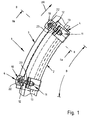
- FIG. 1 is a longitudinal section of a compliant underground arched construction 1 shown, which can be used in mining or tunneling.
- the expansion 1 consists of several identically shaped profile segments 2, 3. In each case two in the circumferential direction UR of the expansion 1 successive profile segments 2, 3 are shown in the FIGS. 1 and 2 nested and in the overlapping area B with the help of two clamped connections 4 arranged at a distance from one another are clamped together so that, when exposed to rock loads, the profile segments 2, 3 which are braced with one another can displace relative to one another to a limited extent, with a shortening of the expansion 1 in the circumferential direction UR.
- the profile segments 2, 3 are identical and each have a U-shaped cross-section, which consists of two curved legs 5, a leg connecting the web 5 6 and two arranged on the web 6 remote from the ends of the legs 5 arranged ears 7.
- the ears 7 are directed sideways outward and have a web 6 facing away from the convex surface area 8 and a web 6 facing the concave area in the form of a throat 9.
- FIG. 2 shows that the nested profile segments 2, 3 are supported against each other such that the convex outer surfaces 8 of the ears 7 of the encompassing profile segment 2 lie in the grooves 9 of the ears 7 of the inner profile segment 3.
- the clamping connections 4 for the nested profile segments 2, 3 each consist of an ears 7 of the engaging profile segment 3 cross-top flap 10, a encompassing profile segment 2 embracing lower flap 11 and two lateral bolts 12 and nuts 13th
- resulting upper flap 10 has a straight central longitudinal section 14, two adjoining this longitudinal section 14 arcuately curved latching portions 15 and two lateral hook-shaped Einitatiflansche 16.
- the locking portions 15 are curved in opposite directions to the Einitatiflanschen 16. It's the FIG. 4 it can be seen that the central longitudinal section 14 is pulled in by approximately the thickness D of the upper flap 10 in the direction of a plane E - E which tangentially affects the convex surfaces 17 of the suspension flanges 16.
- the convex outer surfaces 20 of the locking portions 15 are provided with frontal bevels 21 ( FIGS. 4 to 6 ).
- the bolts have 12 heads 22 which are the contours of the Einschlansche 16 contour-matched and with their shanks 23 recesses 24 in the Ein vonschen 16 and recesses 25 in clamping flanges 26 of the lower flaps 11 (see also FIGS. 7 and 8 ) push through.
- the lower flaps 11 of the clamp connections 4 are U-shaped ( Figures 2 . 3 . 7 and 8 ) and have at the transitions from the lateral straight clamping flanges 26 on curved, connected by a web 27 leg 28 Stauerwulste 29, which are facing the upper flap 10. These Stauerwulste 29 hold in the grooves 9 of the encompassing profile segment. 2
- FIGS. 7 and 8 show FIGS. 7 and 8 in that recesses 30 are provided centrally of these support beads 29, so that the support beads 29 lie only with the end portions in the grooves 9.
- Get profile segments 2, 3 with a larger profile width PB used, as in the FIG. 2 is shown, it can be seen that when tightening the bolt 12 by means of nuts 13 an additional frictional resistance between the upper flap 10 and the ears 7 of the engaging profile segment 3 is constructed by the fact that the mutually facing portions of the inner concave surfaces 18 of the locking portions 15 at the opposite surface portions of the ears 7 according to the arrows PF come to rest.
- the embodiment corresponds to FIG. 3 that of the FIG. 2 , so that can be dispensed with a repeated explanation.
Landscapes
- Engineering & Computer Science (AREA)
- Mining & Mineral Resources (AREA)
- Architecture (AREA)
- Civil Engineering (AREA)
- Structural Engineering (AREA)
- Life Sciences & Earth Sciences (AREA)
- General Life Sciences & Earth Sciences (AREA)
- Geochemistry & Mineralogy (AREA)
- Geology (AREA)
- Lining And Supports For Tunnels (AREA)
- Clamps And Clips (AREA)
Abstract
Description
- Die Erfindung betrifft eine Klemmverbindung für überlappend ineinander liegende U-förmige, seitliche Ohren aufweisende Profilsegmente des nachgiebigen untertägigen Ausbaus gemäß den Merkmalen im Oberbegriff des Anspruchs 1.
- Ein derartiger nachgiebiger untertägiger Ausbau mit U-förmigen Profilsegmenten ist im Umfang der
DE 41 04 798 A1 bekannt. Die Profilsegmente weisen jeweils zwei gebogene Schenkel, einen die Schenkel verbindenden Steg sowie zwei an den dem Steg abgewandten Enden der Schenkel angeordnete, seitwärts gerichtete Flansche auf, die wegen ihrer Form auch Ohren genannt werden. Im Überlappungsbereich von zwei aufeinander folgenden Profilsegmenten werden diese ineinander geschachtelt, wobei sich die Ohren des umgreifenden Profilsegments in Kehlen des einliegenden Profilsegments abstützen, die dort an den Ohren ausgebildet sind. - Die Verspannung der Profilsegmente im Überlappungsbereich erfolgt mit Hilfe von mindestens zwei Klemmverbindungen, wobei sich jede Klemmverbindung aus einer Oberlasche mit seitlichen geraden Einhängeflanschen, einer Unterlasche mit seitlichen geraden Spannflanschen und Ausnehmungen in den Einhängeflanschen und Spannflanschen durchsetzenden Schraubbolzen sowie auf die Schraubbolzen drehbaren Muttern zusammensetzt. Während die Unterlasche weitgehend U-förmig ausgebildet ist und neben den seitlichen Spannflanschen Schenkel und einen die Schenkel verbindenden Steg aufweist, wobei im Übergangsbereich von den Spannflanschen auf die Schenkel Stützwulste vorgesehen sind, die sich in Kehlen der Ohren des umgreifenden Profilsegments abstützen, besteht die Oberlasche aus einem mittleren Längenabschnitt mit einem eingezogenen geraden Zentralbereich sowie sich an diesen Längenabschnitt endseitig anschließenden geraden Einhängeflanschen. Die Schraubbolzen werden mit ihren entsprechend angepassten Köpfen in diese Einhängeflansche eingelegt und durchsetzen mit ihren Schäften Ausnehmungen in den Einhängeflanschen und in den Spannflanschen der Unterlasche. Mit Hilfe auf die Gewindeabschnitte der Schraubbolzen gedrehten Muttern werden dann die Einhängeflansche der Oberlasche und die Spannflansche der Unterlasche gegeneinander gezogen, wobei die Stützwulste der Unterlasche in die Kehlen der Ohren des umgreifenden Profilsegments gedrückt werden und die Oberlasche mit geraden Übergangsabschnitten zwischen dem Zentralbereich und den Einhängeflanschen die Ohren des einliegenden Profilsegments mit Spiel übergreift.
- Hierbei soll die Oberlasche als ein auf zwei Stützen gelagerter Träger wirksam sein, welcher unter dem Einfluss der Schraubenkräfte deformiert wird. Die betriebsgemäße Deformation des Trägers als Lasche kann durch die Formänderung des neutralen Fadens gefolgt werden.
- Der Reibungswiderstand zwischen den überlappend ineinander gelegten Profilsegmenten wird teilweise über definierte und teilweise über undefinierte Druckflächen aus der Normalkraft der Schraubbolzen erzeugt. Hierbei soll über die Kontaktbereiche der Oberlasche mit den Ohren des einliegenden Profilsegments ein Druck erzeugt werden, der einen höheren Einschubwiderstand der Profilsegmente bei auftretender Gebirgslast gewährleisten soll.
- Dieser Einschubwiderstand muss jedoch in Abhängigkeit von den Toleranzen der Profilsegmente und auch ihren Breiten - gemessen über die Außenseiten der Ohren - betrachtet werden. Er ist nur dann wirklich wirksam, wenn die Übergangsbereiche der Oberlasche mit den Ohren des einliegenden Profilsegments in einem einwandfreien Kontakt stehen. Aufgrund diverser Bearbeitungsschritte, wie zum Beispiel dem Vergüten, Biegen der von langen Profilsträngen auf eine Länge von zum Beispiel 8 m abgelängten Profilsegmente kann die Breite der Profilsegmente in bestimmten Grenzen variieren. Dies hat zur Folge, dass eine Klemmverbindung mit einer Oberlasche und Unterlasche insofern einen Mangel besitzen kann, dass die Übergangsbereiche zwischen dem mittleren Längenabschnitt einer Oberlasche und den Einhängeflanschen in keinen einwandfreien Kontakt mit den äußeren Oberflächen der Ohren kommen, so dass der Einschubwiderstand nicht mit der gewünschten Sicherheit bestimmt werden kann.
- Der Erfindung liegt die Aufgabe zugrunde, eine Klemmverbindung für U-förmige Profilsegmente des nachgiebigen untertägigen Ausbaus zu schaffen, bei welcher der von der Oberlasche bestimmte Einschubwiderstand auch dann gewährleistet werden kann, wenn die Breiten der Profilsegmente von dem Nennmaß erheblich abweichen.
- Die Lösung dieser Aufgabe besteht nach der Erfindung in den Merkmalen des Anspruchs 1.
- Vorteilhafte Weiterbildungen der Erfindung sind Gegenstand der Ansprüche 2 bis 6.
- Die Oberlasche soll nunmehr zwischen den gezielt hakenförmig ausgebildeten gekrümmten seitlichen Einhängeflanschen einen eingezogenen, sich geradlinig erstreckenden mittleren Längenabschnitt und zwischen dem mittleren Längenabschnitt und den Einhängeflanschen zu den Einhängeflanschen gegensinnig gekrümmte, die Ohren an dem innen liegenden Profilsegment flächig umfassende Rastabschnitte mit konkaven Innenflächen und konvexen Außenflächen aufweisen. Diese Rastabschnitte umfassen mit ihren Innenflächen die Ohren des einliegenden Profilsegments. In Abhängigkeit von der tatsächlichen Breite eines Profilsegments liegen nunmehr entweder die einander zugewandten Innenflächen der Rastabschnitte an den äußeren Oberflächenbereichen der Ohren oder es liegen die voneinander abgewandten Innenflächen der Rastabschnitte an den einander zugewandten Oberflächenbereichen der Ohren. Beim Anziehen der Muttern kann somit stets der gewünschte Einschubwiderstand sichergestellt werden, weil die von den Schraubbolzen ausgeübten Kräfte immer auf einen Oberflächenbereich der Ohren des einliegenden Profilsegments übertragen werden. Unterstützt wird diese verbesserte Kraftübertragung dadurch, dass die Oberlasche aufgrund des eingezogenen mittleren Längenabschnitts steifer ausgebildet ist.
- Der Einschubwiderstand wird dadurch noch weiter verbessert, dass der mittlere gerade Längenabschnitt der Oberlasche um etwa die Dicke der Oberlasche eingezogen ist.
- Ferner können am Grund der konkaven Innenflächen der Rastabschnitte Taschen ausgebildet sein. Die Taschen sichern eine einwandfreie Anlage der äußeren Oberflächen der Ohren des einliegenden Profilsegments an den konkaven Innenflächen der Rastabschnitte.
- Die quer zu der Oberlasche verlaufenden Taschen können ovale Konturen aufweisen.
- Des Weiteren ist es zweckmäßig, dass die konvexen Außenflächen der Rastabschnitte mit stirnseitigen Fasen versehen sind.
- Um auch der Unterlasche hinsichtlich der Stützwulste zwischen den seitlichen Spannflanschen und den Schenkeln eine einwandfreie Anlage in den Kehlen des umgreifenden Profilsegments zu sichern, sind die Stützwulste mit mittigen Aussparungen versehen. Auf diese Weise liegen die neben den Aussparungen liegenden Bereiche der Stützwulste einwandfrei in den Kehlen der Ohren des umgreifenden Profilsegments.
- Die Erfindung ist nachfolgend anhand von in den Zeichnungen veranschaulichten Ausführungsbeispielen näher erläutert. Es zeigen:
- Figur 1
- einen Abschnitt eines untertägigen Bogenausbaus im Bereich von zwei sich überlappenden Profilsegmenten;
- Figur 2
- einen Querschnitt durch die Darstellung der
Figur 1 entlang der Linie II - II in Richtung der Pfeile II a gesehen; - Figur 3
- die Darstellung der
Figur 2 bei einem Bogenausbau mit schmaleren Profilsegmenten; - Figur 4
- eine Oberlasche einer Klemmverbindung des Bogenausbaus in der Stirnansicht;
- Figur 5
- eine Draufsicht auf einen Endabschnitt der Oberlasche der
Figur 4 in Richtung des Pfeils V gesehen; - Figur 6
- eine Seitenansicht der Oberlasche der
Figur 4 in Richtung des Pfeils VI gesehen; - Figur 7
- eine Stirnansicht auf eine Unterlasche einer Klemmverbindung des Bogenausbaus der
Figur 1 und - Figur 8
- eine Seitenansicht auf die Unterlasche der
Figur 7 in Richtung des Pfeils VIII gesehen. - In der
Figur 1 ist ein Längenabschnitt eines nachgiebigen untertägigen bogenförmigen Ausbaus 1 dargestellt, der im Berg- oder Tunnelbau eingesetzt werden kann. Der Ausbau 1 besteht aus mehreren identisch ausgebildeten Profilsegmenten 2, 3. Jeweils zwei in Umfangsrichtung UR des Ausbaus 1 aufeinander folgende Profilsegmente 2, 3 werden gemäß der Darstellung derFiguren 1 und2 ineinander gelegt und im Überlappungsbereich B mit Hilfe von zwei im Abstand voneinander angeordneten Klemmverbindungen 4 so miteinander verspannt, dass bei Gebirgsbelastungen die miteinander verspannten Profilsegmente 2, 3 sich zueinander relativ begrenzt verlagern können, wobei eine Verkürzung des Ausbaus 1 in Umfangsrichtung UR erfolgt. - Die Profilsegmente 2, 3 sind identisch ausgebildet und weisen jeweils einen U-förmigen Querschnitt auf, der sich aus zwei gekrümmten Schenkeln 5, einen die Schenkel 5 verbindenden Steg 6 und zwei an den dem Steg 6 abgewandten Enden der Schenkel 5 angeordneten Ohren 7 zusammensetzt. Die Ohren 7 sind seitwärts nach außen gerichtet und besitzen einen dem Steg 6 abgewandten konvexen Oberflächenbereich 8 sowie einen dem Steg 6 zugewandten konkaven Bereich in Form einer Kehle 9. Insbesondere die
Figur 2 zeigt, dass die ineinander liegenden Profilsegmente 2, 3 sich derart aneinander abstützen, dass die konvexen äußeren Oberflächen 8 der Ohren 7 des umgreifenden Profilsegments 2 in den Kehlen 9 der Ohren 7 des innen liegenden Profilsegments 3 liegen. - Die Klemmverbindungen 4 für die ineinander liegenden Profilsegmente 2, 3 bestehen jeweils aus einer die Ohren 7 des eingreifenden Profilsegments 3 übergreifenden Oberlasche 10, einer das umgreifende Profilsegment 2 umgreifenden Unterlasche 11 sowie zwei seitlichen Schraubbolzen 12 und Muttern 13.
- Jede aus den
Figuren 4 bis 6 im Einzelnen hervorgehende Oberlasche 10 weist einen geraden mittleren Längenabschnitt 14, zwei sich an diesen Längenabschnitt 14 anschließende bogenförmig gekrümmte Rastabschnitte 15 sowie zwei seitliche hakenförmige Einhängeflansche 16 auf. Die Rastabschnitte 15 sind zu den Einhängeflanschen 16 gegensinnig gekrümmt. Es ist derFigur 4 zu entnehmen, dass der mittlere Längenabschnitt 14 um etwa die Dicke D der Oberlasche 10 in Richtung auf eine Ebene E - E eingezogen ist, welche die konvexen Oberflächen 17 der Einhängeflansche 16 tangiert. - Am Grund der konkaven Innenflächen 18 der Rastabschnitte 15 sind Taschen 19 ausgebildet, die sich quer zu der Oberlasche 10 erstrecken und ovale Konturen aufweisen (
Figuren 4 und 5 ). - Die konvexen Außenflächen 20 der Rastabschnitte 15 sind mit stirnseitigen Fasen 21 versehen (
Figuren 4 bis 6 ). - Wie die
Figuren 1 und2 deutlich zeigen, besitzen die Schraubbolzen 12 Köpfe 22, welche den Innenseiten der Einhängeflansche 16 konturengenau angepasst sind und mit ihren Schäften 23 Ausnehmungen 24 in den Einhängeflanschen 16 und Ausnehmungen 25 in Spannflanschen 26 der Unterlaschen 11 (siehe auchFiguren 7 und 8 ) durchsetzen. - Die Unterlaschen 11 der Klemmverbindungen 4 sind U-förmig gestaltet (
Figuren 2 ,3 ,7 und 8 ) und weisen an den Übergängen von den seitlichen geraden Spannflanschen 26 auf gekrümmte, mittels eines Stegs 27 verbundene Schenkel 28 Stützwulste 29 auf, die der Oberlasche 10 zugewandt sind. Diese Stützwulste 29 fassen in die Kehlen 9 des umgreifenden Profilsegments 2. - Ferner zeigen die
Figuren 7 und 8 , dass mittig dieser Stützwulste 29 Aussparungen 30 vorgesehen sind, so dass die Stützwulste 29 lediglich mit den Endabschnitten in den Kehlen 9 liegen. - Gelangen Profilsegmente 2, 3 mit einer größeren Profilbreite PB zum Einsatz, wie es in der
Figur 2 dargestellt ist, so ist zu sehen, dass beim Anziehen der Schraubbolzen 12 mit Hilfe der Muttern 13 ein zusätzlicher Reibungswiderstand zwischen der Oberlasche 10 und den Ohren 7 des eingreifenden Profilsegments 3 dadurch aufgebaut wird, dass die einander zugewandten Bereiche der inneren konkaven Flächen 18 der Rastabschnitte 15 an den einander abgewandten Oberflächenabschnitten der Ohren 7 gemäß den Pfeilen PF zur Anlage gelangen. - Wird dieselbe Klemmverbindung 4 bei Profilsegmenten 2, 3 mit geringeren Profilbreiten PB1 angewendet (
Figur 3 ), so ist zu sehen, dass beim Anziehen der Schraubbolzen 12 mit Hilfe der Muttern 13 dann die einander abgewandten inneren konkaven Flächen 18 der Rastabschnitte 15 mit den gegenüberliegenden konvexen Oberflächenbereichen 8 der Ohren 7 des eingreifenden Profilsegments 3 in Kontakt gelangen (Pfeile PF1). - Ansonsten entspricht die Ausführungsform der
Figur 3 derjenigen derFigur 2 , so dass von einer nochmaligen Erläuterung abgesehen werden kann. - Bezugszeichen:
- 1 -
- Ausbau
- 2 -
- umgreifendes Profilsegment
- 3 -
- eingreifendes Profilsegment
- 4 -
- Klemmverbindungen
- 5 -
- Schenkel v. 2, 3
- 6 -
- Steg v. 2, 3
- 7 -
- Ohren v. 2, 3
- 8 -
- konvexe Oberflächen v. 7
- 9 -
- Kehlen v. 7
- 10 -
- Oberlasche
- 11 -
- Unterlasche
- 12 -
- Schraubbolzen
- 13 -
- Muttern
- 14 -
- mittlerer Längenabschnitt v. 10
- 15 -
- Rastabschnitte v. 10
- 16 -
- Einhängeflansche v. 10
- 17 -
- konvexe Oberflächen v. 16
- 18 -
- konkave Innenflächen v. 15
- 19 -
- Taschen in 18
- 20 -
- konvexe Außenflächen v. 15
- 21 -
- Fasen an 20
- 22 -
- Köpfe v. 12
- 23 -
- Schäfte v. 12
- 24 -
- Ausnehmungen in 16
- 25 -
- Ausnehmungen in 26
- 26 -
- Spannflansche v. 11
- 27 -
- Steg v. 11
- 28 -
- Schenkel v. 11
- 29 -
- Stützwulste
- 30 -
- Aussparungen in 29
- B -
- Überlappungsbereich
- D -
- Dicke v. 10
- E - E -
- Ebene an 17
- PB -
- Profilbreite
- PB1 -
- Profilbreite
- PF -
- Pfeile
- PF1 -
- Pfeile
- UR -
- Umfangsrichtung v. 1
Claims (6)
- Klemmverbindung (4) für überlappend ineinander liegende U-förmige, seitliche Ohren (7) aufweisende Profilsegmente (2, 3) des nachgiebigen untertägigen Ausbaus (1), welche eine Oberlasche (10) mit seitlichen Einhängeflanschen (16), eine U-förmige Unterlasche (11) mit seitlichen geraden Spannflanschen (26) sowie Stützwulsten (29) und Ausnehmungen (24, 25) in den Einhängeflanschen (16) und Spannflanschen (26) durchsetzende Schraubbolzen (12) sowie auf die Schraubbolzen (12) drehbare Muttern (13) aufweist, dadurch gekennzeichnet, dass die Oberlasche (10) zwischen den hakenförmig ausgebildeten gekrümmten seitlichen Einhängeflanschen (16) einen eingezogenen, sich geradlinig erstreckenden mittleren Längenabschnitt (14) und zwischen dem mittleren Längenabschnitt (14) und den Einhängeflanschen (16) zu den Einhängeflanschen (16) gegensinnig gekrümmte, die Ohren (7) an dem innenliegenden Profilsegment (3) flächig umfassende Rastabschnitte (15) mit konkaven Innenflächen (18) und konvexen Außenflächen (20) aufweist.
- Klemmverbindung nach Anspruch 1, dadurch gekennzeichnet, dass der mittlere Längenabschnitt (14) der Oberlasche (10) um etwa die Dicke (D) der Oberlasche (10) eingezogen ist.
- Klemmverbindung nach Anspruch 1 oder 2, dadurch gekennzeichnet, dass am Grund der konkaven Innenflächen (18) der Rastabschnitte (15) Taschen (19) ausgebildet sind.
- Klemmverbindung nach Anspruch 3, dadurch gekennzeichnet, dass die quer zu der Oberlasche (10) verlaufenden Taschen (19) ovale Konturen aufweisen.
- Klemmverbindung nach einem der Ansprüche 1 bis 4, dadurch gekennzeichnet, dass die konvexen Außenflächen (20) der Rastabschnitte (15) mit stirnseitigen Fasen (21) versehen sind.
- Klemmverbindung nach einem der Ansprüche 1 bis 5, dadurch gekennzeichnet, dass die Stützwulste (29) an der Unterlasche (11) jeweils eine mittige Aussparung (30) aufweisen.
Priority Applications (1)
| Application Number | Priority Date | Filing Date | Title |
|---|---|---|---|
| PL10004197T PL2248995T3 (pl) | 2009-05-08 | 2010-04-20 | Połączenie zaciskowe |
Applications Claiming Priority (1)
| Application Number | Priority Date | Filing Date | Title |
|---|---|---|---|
| DE202009006707U DE202009006707U1 (de) | 2009-05-08 | 2009-05-08 | Klemmverbindung für U-förmige Profilsegmente |
Publications (3)
| Publication Number | Publication Date |
|---|---|
| EP2248995A2 true EP2248995A2 (de) | 2010-11-10 |
| EP2248995A3 EP2248995A3 (de) | 2013-02-27 |
| EP2248995B1 EP2248995B1 (de) | 2014-10-22 |
Family
ID=40874470
Family Applications (1)
| Application Number | Title | Priority Date | Filing Date |
|---|---|---|---|
| EP10004197.9A Not-in-force EP2248995B1 (de) | 2009-05-08 | 2010-04-20 | Klemmverbindung |
Country Status (4)
| Country | Link |
|---|---|
| EP (1) | EP2248995B1 (de) |
| DE (1) | DE202009006707U1 (de) |
| ES (1) | ES2526121T3 (de) |
| PL (1) | PL2248995T3 (de) |
Citations (1)
| Publication number | Priority date | Publication date | Assignee | Title |
|---|---|---|---|---|
| DE4104798A1 (de) | 1991-02-16 | 1993-07-29 | Lenin Kohaszati Muvek | Element zur sicherung eines unterirdischen hohlraums, insbesondere bei grubenraeumen, sowie konstruktion zur verbindung der sicherungselemente |
Family Cites Families (2)
| Publication number | Priority date | Publication date | Assignee | Title |
|---|---|---|---|---|
| DE3245599A1 (de) * | 1982-12-09 | 1984-06-14 | Stahlausbau Gmbh, 4650 Gelsenkirchen | Verbindung fuer gleitbogenausbau |
| DE20200964U1 (de) * | 2002-01-24 | 2002-05-29 | Bochumer Eisenhütte Heintzmann GmbH & Co. KG, 44793 Bochum | Bogenausbau für Strecken und Tunnel, insbesondere für Abbaustrecken in bergbaulchen Untertagebetrieben |
-
2009
- 2009-05-08 DE DE202009006707U patent/DE202009006707U1/de not_active Expired - Lifetime
-
2010
- 2010-04-20 ES ES10004197.9T patent/ES2526121T3/es active Active
- 2010-04-20 EP EP10004197.9A patent/EP2248995B1/de not_active Not-in-force
- 2010-04-20 PL PL10004197T patent/PL2248995T3/pl unknown
Patent Citations (1)
| Publication number | Priority date | Publication date | Assignee | Title |
|---|---|---|---|---|
| DE4104798A1 (de) | 1991-02-16 | 1993-07-29 | Lenin Kohaszati Muvek | Element zur sicherung eines unterirdischen hohlraums, insbesondere bei grubenraeumen, sowie konstruktion zur verbindung der sicherungselemente |
Also Published As
| Publication number | Publication date |
|---|---|
| DE202009006707U1 (de) | 2009-07-16 |
| EP2248995B1 (de) | 2014-10-22 |
| ES2526121T3 (es) | 2015-01-07 |
| PL2248995T3 (pl) | 2015-04-30 |
| EP2248995A3 (de) | 2013-02-27 |
Similar Documents
| Publication | Publication Date | Title |
|---|---|---|
| DE3918091C2 (de) | ||
| EP2976810B1 (de) | Kontaktelement | |
| EP2813783A1 (de) | Ständer zum Abstützen von Solarpaneelen auf einem Flachdach | |
| EP1980361A1 (de) | Verbindungselement und Schutzabdeckung | |
| EP2322719A2 (de) | Vorrichtungen zur Überbrückung von Dehnfugen, Profilkonstruktion und Verfahren zur Herstellung von Fugenprofilen | |
| DE3111876A1 (de) | Federnde schienenbefestigung auf betonschwellen | |
| EP2984231B1 (de) | Winkelführungsplatte für ein schienenprofil | |
| EP2759422B1 (de) | Anhängekupplung | |
| EP3001044B1 (de) | Schrumpfring | |
| WO2004039702A1 (de) | Mitnehmer für kettenkratzförderer, insbesondere des untertagebetriebes | |
| EP2248995B1 (de) | Klemmverbindung | |
| DE102013107866A1 (de) | Gabellaschenkette | |
| EP3111108B1 (de) | Blockschloss mit freistich | |
| EP2982807B1 (de) | Vorrichtung zum Verbinden von zwei durch eine Fuge getrennten Bauteilen | |
| DE202011005479U1 (de) | Herzstück für Weichen | |
| DE102011018351B4 (de) | Herzstück für Weichen | |
| EP3176340B1 (de) | Dichtung, sowie pfosten-riegel-anordnung | |
| EP3284863B1 (de) | Zungenschiene und zungenvorrichtung | |
| DE202005005548U1 (de) | Mit einer bügelförmigen Drahtschutzfeder versehenes elektrisches Kontaktelement | |
| CH665699A5 (de) | Breitbandschelle. | |
| DE102020111132A1 (de) | Profilstrebe, insbesondere für ein Kraftfahrzeug | |
| DE3320829C1 (de) | Umfangsnachgiebiger Ausbaubogen fuer Grubenstrecken,Tunnel oder dergleichen | |
| DE102019209695B4 (de) | Schutzelement für ein Fahrzeug, Schutzanordnung und Fahrzeug | |
| DE102004055556B4 (de) | Verbindungselement für Profile | |
| DE2804378B2 (de) | Flanschverbindung zwischen einer Fahrzeugachse und den Längsholmen eines Fahrgestelles |
Legal Events
| Date | Code | Title | Description |
|---|---|---|---|
| PUAI | Public reference made under article 153(3) epc to a published international application that has entered the european phase |
Free format text: ORIGINAL CODE: 0009012 |
|
| AK | Designated contracting states |
Kind code of ref document: A2 Designated state(s): AT BE BG CH CY CZ DE DK EE ES FI FR GB GR HR HU IE IS IT LI LT LU LV MC MK MT NL NO PL PT RO SE SI SK SM TR |
|
| AX | Request for extension of the european patent |
Extension state: AL BA ME RS |
|
| PUAL | Search report despatched |
Free format text: ORIGINAL CODE: 0009013 |
|
| AK | Designated contracting states |
Kind code of ref document: A3 Designated state(s): AT BE BG CH CY CZ DE DK EE ES FI FR GB GR HR HU IE IS IT LI LT LU LV MC MK MT NL NO PL PT RO SE SI SK SM TR |
|
| AX | Request for extension of the european patent |
Extension state: AL BA ME RS |
|
| RIC1 | Information provided on ipc code assigned before grant |
Ipc: E21D 11/22 20060101AFI20130122BHEP |
|
| 17P | Request for examination filed |
Effective date: 20130404 |
|
| GRAP | Despatch of communication of intention to grant a patent |
Free format text: ORIGINAL CODE: EPIDOSNIGR1 |
|
| INTG | Intention to grant announced |
Effective date: 20140702 |
|
| GRAS | Grant fee paid |
Free format text: ORIGINAL CODE: EPIDOSNIGR3 |
|
| GRAA | (expected) grant |
Free format text: ORIGINAL CODE: 0009210 |
|
| AK | Designated contracting states |
Kind code of ref document: B1 Designated state(s): AT BE BG CH CY CZ DE DK EE ES FI FR GB GR HR HU IE IS IT LI LT LU LV MC MK MT NL NO PL PT RO SE SI SK SM TR |
|
| REG | Reference to a national code |
Ref country code: GB Ref legal event code: FG4D Free format text: NOT ENGLISH |
|
| REG | Reference to a national code |
Ref country code: CH Ref legal event code: EP |
|
| REG | Reference to a national code |
Ref country code: AT Ref legal event code: REF Ref document number: 692764 Country of ref document: AT Kind code of ref document: T Effective date: 20141115 |
|
| REG | Reference to a national code |
Ref country code: IE Ref legal event code: FG4D Free format text: LANGUAGE OF EP DOCUMENT: GERMAN |
|
| REG | Reference to a national code |
Ref country code: DE Ref legal event code: R096 Ref document number: 502010008089 Country of ref document: DE Effective date: 20141204 |
|
| REG | Reference to a national code |
Ref country code: ES Ref legal event code: FG2A Ref document number: 2526121 Country of ref document: ES Kind code of ref document: T3 Effective date: 20150107 |
|
| REG | Reference to a national code |
Ref country code: NL Ref legal event code: VDEP Effective date: 20141022 |
|
| REG | Reference to a national code |
Ref country code: LT Ref legal event code: MG4D |
|
| PG25 | Lapsed in a contracting state [announced via postgrant information from national office to epo] |
Ref country code: FI Free format text: LAPSE BECAUSE OF FAILURE TO SUBMIT A TRANSLATION OF THE DESCRIPTION OR TO PAY THE FEE WITHIN THE PRESCRIBED TIME-LIMIT Effective date: 20141022 Ref country code: IS Free format text: LAPSE BECAUSE OF FAILURE TO SUBMIT A TRANSLATION OF THE DESCRIPTION OR TO PAY THE FEE WITHIN THE PRESCRIBED TIME-LIMIT Effective date: 20150222 Ref country code: LT Free format text: LAPSE BECAUSE OF FAILURE TO SUBMIT A TRANSLATION OF THE DESCRIPTION OR TO PAY THE FEE WITHIN THE PRESCRIBED TIME-LIMIT Effective date: 20141022 Ref country code: NO Free format text: LAPSE BECAUSE OF FAILURE TO SUBMIT A TRANSLATION OF THE DESCRIPTION OR TO PAY THE FEE WITHIN THE PRESCRIBED TIME-LIMIT Effective date: 20150122 Ref country code: PT Free format text: LAPSE BECAUSE OF FAILURE TO SUBMIT A TRANSLATION OF THE DESCRIPTION OR TO PAY THE FEE WITHIN THE PRESCRIBED TIME-LIMIT Effective date: 20150223 Ref country code: NL Free format text: LAPSE BECAUSE OF FAILURE TO SUBMIT A TRANSLATION OF THE DESCRIPTION OR TO PAY THE FEE WITHIN THE PRESCRIBED TIME-LIMIT Effective date: 20141022 |
|
| REG | Reference to a national code |
Ref country code: PL Ref legal event code: T3 |
|
| PG25 | Lapsed in a contracting state [announced via postgrant information from national office to epo] |
Ref country code: SE Free format text: LAPSE BECAUSE OF FAILURE TO SUBMIT A TRANSLATION OF THE DESCRIPTION OR TO PAY THE FEE WITHIN THE PRESCRIBED TIME-LIMIT Effective date: 20141022 Ref country code: HR Free format text: LAPSE BECAUSE OF FAILURE TO SUBMIT A TRANSLATION OF THE DESCRIPTION OR TO PAY THE FEE WITHIN THE PRESCRIBED TIME-LIMIT Effective date: 20141022 Ref country code: CY Free format text: LAPSE BECAUSE OF FAILURE TO SUBMIT A TRANSLATION OF THE DESCRIPTION OR TO PAY THE FEE WITHIN THE PRESCRIBED TIME-LIMIT Effective date: 20141022 Ref country code: LV Free format text: LAPSE BECAUSE OF FAILURE TO SUBMIT A TRANSLATION OF THE DESCRIPTION OR TO PAY THE FEE WITHIN THE PRESCRIBED TIME-LIMIT Effective date: 20141022 Ref country code: GR Free format text: LAPSE BECAUSE OF FAILURE TO SUBMIT A TRANSLATION OF THE DESCRIPTION OR TO PAY THE FEE WITHIN THE PRESCRIBED TIME-LIMIT Effective date: 20150123 |
|
| REG | Reference to a national code |
Ref country code: DE Ref legal event code: R097 Ref document number: 502010008089 Country of ref document: DE |
|
| PG25 | Lapsed in a contracting state [announced via postgrant information from national office to epo] |
Ref country code: RO Free format text: LAPSE BECAUSE OF FAILURE TO SUBMIT A TRANSLATION OF THE DESCRIPTION OR TO PAY THE FEE WITHIN THE PRESCRIBED TIME-LIMIT Effective date: 20141022 Ref country code: SK Free format text: LAPSE BECAUSE OF FAILURE TO SUBMIT A TRANSLATION OF THE DESCRIPTION OR TO PAY THE FEE WITHIN THE PRESCRIBED TIME-LIMIT Effective date: 20141022 Ref country code: DK Free format text: LAPSE BECAUSE OF FAILURE TO SUBMIT A TRANSLATION OF THE DESCRIPTION OR TO PAY THE FEE WITHIN THE PRESCRIBED TIME-LIMIT Effective date: 20141022 Ref country code: EE Free format text: LAPSE BECAUSE OF FAILURE TO SUBMIT A TRANSLATION OF THE DESCRIPTION OR TO PAY THE FEE WITHIN THE PRESCRIBED TIME-LIMIT Effective date: 20141022 |
|
| PLBE | No opposition filed within time limit |
Free format text: ORIGINAL CODE: 0009261 |
|
| STAA | Information on the status of an ep patent application or granted ep patent |
Free format text: STATUS: NO OPPOSITION FILED WITHIN TIME LIMIT |
|
| PG25 | Lapsed in a contracting state [announced via postgrant information from national office to epo] |
Ref country code: IT Free format text: LAPSE BECAUSE OF FAILURE TO SUBMIT A TRANSLATION OF THE DESCRIPTION OR TO PAY THE FEE WITHIN THE PRESCRIBED TIME-LIMIT Effective date: 20141022 |
|
| 26N | No opposition filed |
Effective date: 20150723 |
|
| PG25 | Lapsed in a contracting state [announced via postgrant information from national office to epo] |
Ref country code: MC Free format text: LAPSE BECAUSE OF FAILURE TO SUBMIT A TRANSLATION OF THE DESCRIPTION OR TO PAY THE FEE WITHIN THE PRESCRIBED TIME-LIMIT Effective date: 20141022 Ref country code: LU Free format text: LAPSE BECAUSE OF FAILURE TO SUBMIT A TRANSLATION OF THE DESCRIPTION OR TO PAY THE FEE WITHIN THE PRESCRIBED TIME-LIMIT Effective date: 20150420 |
|
| REG | Reference to a national code |
Ref country code: CH Ref legal event code: PL |
|
| GBPC | Gb: european patent ceased through non-payment of renewal fee |
Effective date: 20150420 |
|
| REG | Reference to a national code |
Ref country code: IE Ref legal event code: MM4A |
|
| PG25 | Lapsed in a contracting state [announced via postgrant information from national office to epo] |
Ref country code: LI Free format text: LAPSE BECAUSE OF NON-PAYMENT OF DUE FEES Effective date: 20150430 Ref country code: CH Free format text: LAPSE BECAUSE OF NON-PAYMENT OF DUE FEES Effective date: 20150430 Ref country code: GB Free format text: LAPSE BECAUSE OF NON-PAYMENT OF DUE FEES Effective date: 20150420 |
|
| PG25 | Lapsed in a contracting state [announced via postgrant information from national office to epo] |
Ref country code: SI Free format text: LAPSE BECAUSE OF FAILURE TO SUBMIT A TRANSLATION OF THE DESCRIPTION OR TO PAY THE FEE WITHIN THE PRESCRIBED TIME-LIMIT Effective date: 20141022 |
|
| REG | Reference to a national code |
Ref country code: FR Ref legal event code: PLFP Year of fee payment: 7 |
|
| PG25 | Lapsed in a contracting state [announced via postgrant information from national office to epo] |
Ref country code: IE Free format text: LAPSE BECAUSE OF NON-PAYMENT OF DUE FEES Effective date: 20150420 |
|
| PGFP | Annual fee paid to national office [announced via postgrant information from national office to epo] |
Ref country code: TR Payment date: 20160325 Year of fee payment: 7 |
|
| PGFP | Annual fee paid to national office [announced via postgrant information from national office to epo] |
Ref country code: PL Payment date: 20160323 Year of fee payment: 7 |
|
| PGFP | Annual fee paid to national office [announced via postgrant information from national office to epo] |
Ref country code: CZ Payment date: 20160419 Year of fee payment: 7 Ref country code: DE Payment date: 20160422 Year of fee payment: 7 Ref country code: ES Payment date: 20160414 Year of fee payment: 7 |
|
| PGFP | Annual fee paid to national office [announced via postgrant information from national office to epo] |
Ref country code: AT Payment date: 20160421 Year of fee payment: 7 Ref country code: FR Payment date: 20160421 Year of fee payment: 7 |
|
| PG25 | Lapsed in a contracting state [announced via postgrant information from national office to epo] |
Ref country code: MT Free format text: LAPSE BECAUSE OF FAILURE TO SUBMIT A TRANSLATION OF THE DESCRIPTION OR TO PAY THE FEE WITHIN THE PRESCRIBED TIME-LIMIT Effective date: 20141022 |
|
| PG25 | Lapsed in a contracting state [announced via postgrant information from national office to epo] |
Ref country code: SM Free format text: LAPSE BECAUSE OF FAILURE TO SUBMIT A TRANSLATION OF THE DESCRIPTION OR TO PAY THE FEE WITHIN THE PRESCRIBED TIME-LIMIT Effective date: 20141022 Ref country code: BG Free format text: LAPSE BECAUSE OF FAILURE TO SUBMIT A TRANSLATION OF THE DESCRIPTION OR TO PAY THE FEE WITHIN THE PRESCRIBED TIME-LIMIT Effective date: 20141022 Ref country code: HU Free format text: LAPSE BECAUSE OF FAILURE TO SUBMIT A TRANSLATION OF THE DESCRIPTION OR TO PAY THE FEE WITHIN THE PRESCRIBED TIME-LIMIT; INVALID AB INITIO Effective date: 20100420 |
|
| PG25 | Lapsed in a contracting state [announced via postgrant information from national office to epo] |
Ref country code: BE Free format text: LAPSE BECAUSE OF NON-PAYMENT OF DUE FEES Effective date: 20150430 |
|
| REG | Reference to a national code |
Ref country code: DE Ref legal event code: R119 Ref document number: 502010008089 Country of ref document: DE |
|
| REG | Reference to a national code |
Ref country code: AT Ref legal event code: MM01 Ref document number: 692764 Country of ref document: AT Kind code of ref document: T Effective date: 20170420 |
|
| REG | Reference to a national code |
Ref country code: FR Ref legal event code: ST Effective date: 20171229 |
|
| PG25 | Lapsed in a contracting state [announced via postgrant information from national office to epo] |
Ref country code: CZ Free format text: LAPSE BECAUSE OF NON-PAYMENT OF DUE FEES Effective date: 20170420 Ref country code: AT Free format text: LAPSE BECAUSE OF NON-PAYMENT OF DUE FEES Effective date: 20170420 Ref country code: FR Free format text: LAPSE BECAUSE OF NON-PAYMENT OF DUE FEES Effective date: 20170502 Ref country code: DE Free format text: LAPSE BECAUSE OF NON-PAYMENT OF DUE FEES Effective date: 20171103 |
|
| PG25 | Lapsed in a contracting state [announced via postgrant information from national office to epo] |
Ref country code: MK Free format text: LAPSE BECAUSE OF FAILURE TO SUBMIT A TRANSLATION OF THE DESCRIPTION OR TO PAY THE FEE WITHIN THE PRESCRIBED TIME-LIMIT Effective date: 20141022 |
|
| REG | Reference to a national code |
Ref country code: ES Ref legal event code: FD2A Effective date: 20180706 |
|
| PG25 | Lapsed in a contracting state [announced via postgrant information from national office to epo] |
Ref country code: PL Free format text: LAPSE BECAUSE OF NON-PAYMENT OF DUE FEES Effective date: 20170420 Ref country code: ES Free format text: LAPSE BECAUSE OF NON-PAYMENT OF DUE FEES Effective date: 20170421 |
|
| PG25 | Lapsed in a contracting state [announced via postgrant information from national office to epo] |
Ref country code: TR Free format text: LAPSE BECAUSE OF NON-PAYMENT OF DUE FEES Effective date: 20170420 |