EP2248640B1 - Cutting machine for food - Google Patents
Cutting machine for food Download PDFInfo
- Publication number
- EP2248640B1 EP2248640B1 EP20100004850 EP10004850A EP2248640B1 EP 2248640 B1 EP2248640 B1 EP 2248640B1 EP 20100004850 EP20100004850 EP 20100004850 EP 10004850 A EP10004850 A EP 10004850A EP 2248640 B1 EP2248640 B1 EP 2248640B1
- Authority
- EP
- European Patent Office
- Prior art keywords
- drive
- removal means
- profile
- control device
- parameter
- Prior art date
- Legal status (The legal status is an assumption and is not a legal conclusion. Google has not performed a legal analysis and makes no representation as to the accuracy of the status listed.)
- Active
Links
Images


Classifications
-
- B—PERFORMING OPERATIONS; TRANSPORTING
- B26—HAND CUTTING TOOLS; CUTTING; SEVERING
- B26D—CUTTING; DETAILS COMMON TO MACHINES FOR PERFORATING, PUNCHING, CUTTING-OUT, STAMPING-OUT OR SEVERING
- B26D7/00—Details of apparatus for cutting, cutting-out, stamping-out, punching, perforating, or severing by means other than cutting
- B26D7/27—Means for performing other operations combined with cutting
- B26D7/32—Means for performing other operations combined with cutting for conveying or stacking cut product
-
- B—PERFORMING OPERATIONS; TRANSPORTING
- B26—HAND CUTTING TOOLS; CUTTING; SEVERING
- B26D—CUTTING; DETAILS COMMON TO MACHINES FOR PERFORATING, PUNCHING, CUTTING-OUT, STAMPING-OUT OR SEVERING
- B26D5/00—Arrangements for operating and controlling machines or devices for cutting, cutting-out, stamping-out, punching, perforating, or severing by means other than cutting
-
- B—PERFORMING OPERATIONS; TRANSPORTING
- B26—HAND CUTTING TOOLS; CUTTING; SEVERING
- B26D—CUTTING; DETAILS COMMON TO MACHINES FOR PERFORATING, PUNCHING, CUTTING-OUT, STAMPING-OUT OR SEVERING
- B26D1/00—Cutting through work characterised by the nature or movement of the cutting member or particular materials not otherwise provided for; Apparatus or machines therefor; Cutting members therefor
- B26D1/01—Cutting through work characterised by the nature or movement of the cutting member or particular materials not otherwise provided for; Apparatus or machines therefor; Cutting members therefor involving a cutting member which does not travel with the work
- B26D1/12—Cutting through work characterised by the nature or movement of the cutting member or particular materials not otherwise provided for; Apparatus or machines therefor; Cutting members therefor involving a cutting member which does not travel with the work having a cutting member moving about an axis
- B26D1/14—Cutting through work characterised by the nature or movement of the cutting member or particular materials not otherwise provided for; Apparatus or machines therefor; Cutting members therefor involving a cutting member which does not travel with the work having a cutting member moving about an axis with a circular cutting member, e.g. disc cutter
- B26D1/143—Cutting through work characterised by the nature or movement of the cutting member or particular materials not otherwise provided for; Apparatus or machines therefor; Cutting members therefor involving a cutting member which does not travel with the work having a cutting member moving about an axis with a circular cutting member, e.g. disc cutter rotating about a stationary axis
-
- B—PERFORMING OPERATIONS; TRANSPORTING
- B26—HAND CUTTING TOOLS; CUTTING; SEVERING
- B26D—CUTTING; DETAILS COMMON TO MACHINES FOR PERFORATING, PUNCHING, CUTTING-OUT, STAMPING-OUT OR SEVERING
- B26D2210/00—Machines or methods used for cutting special materials
- B26D2210/02—Machines or methods used for cutting special materials for cutting food products, e.g. food slicers
Definitions
- the invention relates to a method for controlling a cutting machine, as well as a cutting machine for food.
- a method and an apparatus according to the preamble of claims 1 and 7 are approximately from the EP 0 574 649 A1 known.
- the DE 29 42 418 C2 also shows a food slicer with a powered slicer.
- the drive is a multi-pole electromagnet used to better control the reversing of the blower.
- the invention has for its object to develop a control of a cutting machine, which makes it possible to achieve the best possible storage image even with different cutting material.
- the cutting machine has a beater connected to a control device. This controls the decoy on the basis of different drive profiles, wherein a drive profile is determined based on a predetermined parameter.
- a parameter z. B. serve the thickness of the disc or the diameter of the separated food slices.
- the separated slices adhere to different degrees on the transport chain frame depending on their slice thickness or their diameter.
- the food slices are skewered on thorns of the transport chains of the chain frame and must be removed there from a slapper. This force depends on the thickness of the disc or the diameter of the disc. There is also the danger that very thin disks will be damaged by a wrongly sized release force.
- a matching drive profile now varies the release force of the discs by variably controlling the initial torque of the decanter, depending on the parameter.
- the type of food to be cut such as. Cheese, sausage, meat, fish or vegetables. Each of these foods has an individual liability or
- the drive profile can make further variations of the drive.
- the path in particular the swivel angle or the speed is varied depending on a desired storage position of the food slices.
- a database which has a number of different drive profiles.
- the control device determines the drive profile most suitable for the respective task via a selection and controls the stripper on the basis of this selected drive profile.
- the selection of the drive profiles, the control device based on fixed assignments between parameters and drive profiles, preferably look-up tables, or make an algorithm.
- control device has an optimization algorithm and the drive profile is determined on the basis of the predetermined parameters by calculating an individual drive profile with this optimization algorithm or by adapting an existing drive profile with the optimization algorithm.
- the specification of the parameters can be particularly comfortable already by the mandatory for a cutting operation settings of the cutting machine, such. B. the thickness or by transmitting the values from another central control unit automatically. In that case, an additional operation step for manually entering the parameters is not necessary.
- the cutting machine has an input device connected to the control device, preferably a keyboard or a touch screen, for the manual input of parameters.
- the control device controls the drive motor of the Abellers to achieve the corresponding drive profile.
- the drive motor can be designed as a synchronous electric motor or stepper motor.
- the control can be effected by selectively varying the supply current of the drive motor, in particular the polarity, and / or the frequency and / or the current consumption.
- a specific drive torque, and / or a specific reversal point and / or a specific speed of the decanter can be set at any time.
- a particularly good result can be achieved by providing a sensor which provides the control device with feedback about the path or the speed of the blower gives.
- a displacement sensor can be connected to the drive motor or the striker.
- the necessary torque and thus the weight of the food slices to be transported can be determined on the basis of the parameters of the drive motor, in particular the power consumption.
- the necessary torque and thus the weight of the food slices to be transported can be determined on the basis of the parameters of the drive motor, in particular the power consumption.
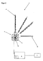
- FIG. 1 schematically the structure of a cutting machine 1 is shown.
- a so-called vertical cutter is shown. That is, the cutting machine 1 has a driven cutting blade 11 which rotates in a vertical cutting plane B.
- a cutting gap is set.
- the width of the cutting gap determines the thickness of the sliced from a food strand 14 slices.
- the cut-off wheels are picked up by a transport device and deposited on a storage table 43 via a transport chain frame 3 and a storage device 4. From there, the separated slices can be removed.
- the food strand 14 is placed on a carriage 12 for cutting and guided by this.
- the carriage 12 is arranged perpendicular to the cutting blade 11 or the cutting plane B and mounted parallel to the cutting plane B displaceable in a machine housing 15.
- the machine housing 15 accommodates the drive motors and control devices of the cutting machine 1.
- the carriage 12 is driven for cutting either manually or by motor, wherein each cut a stroke is performed.
- the carriage 12 At its front, d. H. on the side facing an operator, the carriage 12 has a hand guard plate which covers the carriage 12 to the front. The handguard prevents an operator from inadvertently getting his hand into the cutting area of the knife 11.
- the carriage 12 When cutting, it is necessary that the food strand 14 of the cutting plane B and the cutting blade 11 is continuously delivered.
- the carriage 12 has an infeed device 13 which delivers the material 14 to be cut.
- the separated slices of food strand are received behind the cutting blade 11 of the transport chain frame 3, which has a plurality of parallel circumferential chains 31 for the transport of separated slices.
- the chains 31 have to hold the discs on chain links with wire tips, are impaled on the food slices.
- the discarding takes place by means of a storage device 4, which in the Figures 2 and 3 is shown enlarged.
- the laying device 4 comprises a knocker 41, which is mounted pivotably about a horizontally extending axis of rotation A.
- the stripper 41 has a plurality of spaced fingers 42 which engage between the circulating chains 31 of the transport chain frame 3 and deposit the discs on a shelf 43.
- the striker 41 pivots about a horizontal axis of rotation A. In doing so, it releases the discs which are stuck on the chain tips and carries them along in its pivoting movement
- the sequence of movement of the Abellers 41 when placing the discs on the shelf 43 is shown.
- the movement sequence of the whipper 41 is variable and is controlled by a control device 6 in accordance with a specific drive profile. In this case, the moment, and / or the speed, and / or the route, and / or the turning point of the punch 41 can be made variable based.
- the beater 41 is pivotally mounted about a horizontal axis A.
- An output shaft 51 of an electric Drive motor 5 is connected to the lower portion of the striker 41.
- the FIG. 2 illustrated variant shows a solution that forms the output shaft 51 of the motor 5, the pivot axis A of the Abellers.
- the Abeller 41 is connected via a gear with a toothed belt 52 to the output shaft 51.
- a control unit 6 is arranged in the machine housing 15 and controls the electric drive motor 5 via a connecting line.
- the electric drive motor 5 has a sensor which measures the position or the path of the striker 41 and transmits it to the control unit 6.
- the controller 6 can thus determine the necessary drive torque or the required speed based on a desired drive profile and drive the drive motor 5 exactly.
- the drive profile is determined automatically by the control unit 6 by selecting a specific drive profile from a selection of a plurality of drive profiles stored in parallel in the memory 61.
- criteria for the selection of the drive profile serve parameters such as the type of material to be cut, the diameter of the material to be cut, the thickness of the separated slices and the desired storage image and / or the desired cutting speed. These criteria are transmitted to the control unit 6 from a central cutting machine control, or entered directly via an input device 7.
Description
Die Erfindung betrifft ein Verfahren zum Steuern einer Schneidemaschine, sowie eine Schneidemaschine für Lebensmittel. Ein Verfahren und eine Vorrichtung gemäß des Oberbegriffs der Ansprüche 1 und 7 sind etwa aus der
Aus der
Die
In der Praxis stellt sich oft das Problem, mit dem Schnittgut ein exaktes Ablagebild zu schaffen. Es hat sich gezeigt, dass unterschiedliche Lebensmittelscheiben sich jeweils individuell verhalten, indem sie z. B. unterschiedlich stark an dem Kettenrahmen haften oder nach dem Verlassen des Abschlägers auf der Bahn bis hin zu der Ablagefläche eine eigene Flugcharakteristik aufweisen.In practice, the problem often arises of creating a precise storage image with the clippings. It has been shown that different food slices each behave individually by z. B. different degrees of adhesion to the chain frame or have after leaving the Abschlägers on the web up to the storage area own flight characteristics.
Der Erfindung liegt die Aufgabe zugrunde eine Steuerung einer Schneidemaschine zu entwickeln, die es ermöglicht, auch bei unterschiedlichem Schneidgut ein möglichst gutes Ablagebild zu erzielen.The invention has for its object to develop a control of a cutting machine, which makes it possible to achieve the best possible storage image even with different cutting material.
Diese Aufgabe wird erfindungsgemäß durch ein Verfahren nach den Merkmalen des Anspruchs 1 und eine Schneidemaschine nach den Merkmalen des Anspruchs 7 gelöst.This object is achieved by a method according to the features of claim 1 and a cutting machine according to the features of claim 7.
Die Schneidemaschine weist einen mit einer Steuerungsvorrichtung verbundenen Abschläger auf. Diese steuert den Abschläger anhand unterschiedlicher Antriebsprofile, wobei ein Antriebsprofil anhand eines vorgegebenen Parameters bestimmt wird. Als Parameter kann z. B. die Scheibendicke oder der Scheibendurchmesser der abgetrennten Lebensmittelscheiben dienen. Die abgetrennten Scheiben haften auf dem Transportkettenrahmen abhängig von ihrer Scheibendicke oder ihrem Durchmesser unterschiedlich stark. Vorzugsweise werden die Lebensmittelscheiben auf Dornen der Transportketten des Kettenrahmens aufgespießt und müssen dort von einem Abschläger herausgelöst werden. Diese Kraft ist abhängig von der Scheibendicke bzw. dem Scheibendurchmesser. Es besteht auch die Gefahr, dass sehr dünne Scheiben durch eine falsch bemessene Auslösekraft beschädigt werden. Ein passendes Antriebsprofil variiert nun die Auslösekraft der Scheiben, indem das Anfangsmoment des Abschlägers abhängig von dem Parameter variabel gesteuert wird. Darüber hinaus ist als weiterer Parameter die Art des zu schneidenden Lebensmittels, wie z. B. Käse, Wurst, Fleisch, Fisch oder Gemüse vorgesehen. Jedes dieser Lebensmittel besitzt eine individuelle Haftung bzw.The cutting machine has a beater connected to a control device. This controls the decoy on the basis of different drive profiles, wherein a drive profile is determined based on a predetermined parameter. As a parameter z. B. serve the thickness of the disc or the diameter of the separated food slices. The separated slices adhere to different degrees on the transport chain frame depending on their slice thickness or their diameter. Preferably, the food slices are skewered on thorns of the transport chains of the chain frame and must be removed there from a slapper. This force depends on the thickness of the disc or the diameter of the disc. There is also the danger that very thin disks will be damaged by a wrongly sized release force. A matching drive profile now varies the release force of the discs by variably controlling the initial torque of the decanter, depending on the parameter. In addition, the type of food to be cut, such as. Cheese, sausage, meat, fish or vegetables. Each of these foods has an individual liability or
Ablösekraft vom Transportkettenrahmen, die mit einem entsprechenden Antriebsprofil berücksichtigt wird.Removal force from the transport chain frame, which is taken into account with a corresponding drive profile.
Außer der Auslösekraft kann das Antriebsprofil noch weitere Variationen des Antriebs vornehmen. So ist beispielsweise vorgesehen, dass der Weg, insbesondere der Schwenkwinkel oder die Geschwindigkeit abhängig von einer gewünschten Ablageposition der Lebensmittelscheiben variiert wird. In der Praxis ist es oftmals wünschenswert aus mehreren Scheiben des Schnittguts zweidimensionale Figuren wie z. B. Kreise oder Vierecke zu legen. Dabei ist eine exakte Positionierung jeder einzelnen Scheibe wichtig. Über die variable Steuerung des Schwenkwinkels und/oder der Geschwindigkeit und/oder des Umkehrpunkts des Abschlägers kann eine verbesserte Genauigkeit bei der Positionierung der Scheiben erzielt werden.In addition to the release force, the drive profile can make further variations of the drive. For example, it is provided that the path, in particular the swivel angle or the speed is varied depending on a desired storage position of the food slices. In practice, it is often desirable from several slices of the crop two-dimensional figures such. B. circles or squares to lay. An exact positioning of each individual disc is important. By the variable control of the swivel angle and / or the speed and / or the reversal point of the whipper, an improved accuracy in the positioning of the slices can be achieved.
In einer Ausführung ist vorgesehen, dass eine Datenbank vorgesehen ist, die eine Anzahl an unterschiedlichen Antriebsprofilen aufweist. Anhand der vorgegebenen Parameter bestimmt die Steuerungsvorrichtung das für die jeweilige Aufgabe am besten geeignete Antriebsprofil über eine Selektion und steuert den Abschläger anhand dieses selektierten Antriebsprofils. Die Auswahl der Antriebsprofile kann die Steuerungsvorrichtung anhand fester Zuordnungen zwischen Parametern und Antriebsprofilen, vorzugsweise Verweistabellen, oder anhand eines Algorithmus vornehmen.In one embodiment, it is provided that a database is provided which has a number of different drive profiles. On the basis of the predetermined parameters, the control device determines the drive profile most suitable for the respective task via a selection and controls the stripper on the basis of this selected drive profile. The selection of the drive profiles, the control device based on fixed assignments between parameters and drive profiles, preferably look-up tables, or make an algorithm.
In einer Ausführung kann vorgesehen sein, dass die Steuerungsvorrichtung einen Optimierungsalgorithmus aufweist und das Antriebsprofil anhand der vorgegebenen Parameter bestimmt, indem ein individuelles Antriebsprofil mit diesem Optimierungsalgorithmus berechnet wird oder indem ein vorhandenes Antriebsprofil mit dem Optimierungsalgorithmus angepasst wird.In an embodiment it can be provided that the control device has an optimization algorithm and the drive profile is determined on the basis of the predetermined parameters by calculating an individual drive profile with this optimization algorithm or by adapting an existing drive profile with the optimization algorithm.
Die Vorgabe der Parameter kann besonders komfortabel bereits durch die für einen Schneidebetrieb zwingend notwendigen Einstellungen der Schneidemaschine, wie z. B. der Scheibendicke oder durch Übermitteln der Werte aus einem weiteren zentralen Steuergerät automatisch erfolgen. In dem Fall ist ein zusätzlicher Bedienungsschritt zur manuellen Eingabe der Parameter nicht notwendig. Es ist jedoch auch vorgesehen, dass die Schneidemaschine eine mit der Steuerungsvorrichtung verbundene Eingabevorrichtung, vorzugsweise Tastatur oder Touch-Screen, zur manuellen Eingabe von Parametern aufweist.The specification of the parameters can be particularly comfortable already by the mandatory for a cutting operation settings of the cutting machine, such. B. the thickness or by transmitting the values from another central control unit automatically. In that case, an additional operation step for manually entering the parameters is not necessary. However, it is also envisaged that the cutting machine has an input device connected to the control device, preferably a keyboard or a touch screen, for the manual input of parameters.
In einer Ausführung ist vorgesehen, dass die Steuerungsvorrichtung den Antriebsmotor des Abschlägers steuert, um das entsprechende Antriebsprofil zu erzielen. Der Antriebsmotor kann als elektrischer Synchronmotor oder Schrittmotor ausgeführt sein. Die Steuerung kann erfolgen, indem der Speisestrom des Antriebsmotors, insbesondere die Polarität, und/oder die Frequenz und/oder die Stromaufnahme gezielt variiert wird. So kann zu jedem Zeitpunkt ein bestimmtes Antriebsmoment, und/oder ein bestimmter Umkehrpunkt und/oder eine bestimmte Geschwindigkeit des Abschlägers eingestellt werden. Ein besonders gutes Ergebnis lässt sich erzielen, indem ein Sensor vorgesehen ist, der der Steuerungsvorrichtung eine Rückmeldung über den Weg bzw. die Geschwindigkeit des Abschlägers gibt. Insbesondere kann ein Wegsensor mit dem Antriebsmotor oder dem Abschläger verbunden sein. Alternativ oder zusätzlich kann anhand der Parameter des Antriebsmotors, insbesondere der Stromaufnahme das notwendige Drehmoment und damit das Gewicht der zu transportierenden Lebensmittelscheiben ermittelt werden. Durch Auswertung der Sensorsignale und/oder der Parameter des Antriebsmotors in der Steuerungsvorrichtung kann eine exakte Regelung des Abschlägers erzielt werden.In one embodiment, it is provided that the control device controls the drive motor of the Abschlägers to achieve the corresponding drive profile. The drive motor can be designed as a synchronous electric motor or stepper motor. The control can be effected by selectively varying the supply current of the drive motor, in particular the polarity, and / or the frequency and / or the current consumption. Thus, a specific drive torque, and / or a specific reversal point and / or a specific speed of the decanter can be set at any time. A particularly good result can be achieved by providing a sensor which provides the control device with feedback about the path or the speed of the blower gives. In particular, a displacement sensor can be connected to the drive motor or the striker. Alternatively or additionally, the necessary torque and thus the weight of the food slices to be transported can be determined on the basis of the parameters of the drive motor, in particular the power consumption. By evaluating the sensor signals and / or the parameters of the drive motor in the control device, an exact control of the Abschlägers can be achieved.
Weitere Ausführungsbeispiele der Erfindung sind in den Figuren dargestellt und der dazugehörenden Beschreibung beschrieben.Further embodiments of the invention are illustrated in the figures and the associated description.
Es zeigen,
-
Figur 1 : Eine schematische Schnittdarstellung einer erfindungsgemäßen Schneidemaschine mit gesteuertem Abschläger; -
Figur 2 : Eine schematische Seitenansicht des Antriebs des Abschlägers mit Steuerungsvorrichtung; -
Figur 3 : Eine Variante des Antriebs des Abschlägers.
-
FIG. 1 : A schematic sectional view of a cutting machine according to the invention with a controlled stripper; -
FIG. 2 : A schematic side view of the drive of Abblägers with control device; -
FIG. 3 : A variant of the drive of the blower.
In der
Über eine verstellbare Anschlagplatte, die parallel zum Schneidmesser 11 angeordnet ist, wird ein Schneidspalt eingestellt. Die Breite des Schneidspaltes bestimmt die Dicke der von einem Lebensmittelstrang 14 abgeschnittenen Scheiben. Die abgeschnittenen Scheiben werden von einer Transportvorrichtung aufgenommen und über einen Transportkettenrahmen 3 und eine Ablagevorrichtung 4 auf einen Ablagetisch 43 abgelegt. Von dort können die abgetrennten Scheiben entnommen werden.Via an adjustable stop plate, which is arranged parallel to the
Der Lebensmittelstrang 14 wird zum Schneiden auf einen Schlitten 12 aufgelegt und von diesem geführt. Der Schlitten 12 ist senkrecht zu dem Schneidmesser 11 bzw. der Schneidebene B angeordnet und parallel zu der Schneidebene B verschiebbar in einem Maschinengehäuse 15 gelagert. Das Maschinengehäuse 15 nimmt die Antriebsmotoren und Steuergeräte der Schneidemaschine 1 auf. Der Schlitten 12 wird zum Schneiden entweder manuell oder motorisch angetrieben, wobei je Schnitt ein Hub ausgeführt wird. An seiner Vorderseite, d. h. an der einem Bediener zugewandten Seite, weist der Schlitten 12 eine Handschutzplatte auf, die den Schlitten 12 nach vorne abdeckt. Die Handschutzplatte verhindert, dass ein Bediener unbeabsichtigt mit seiner Hand in den Schneidebereich des Messers 11 gelangt.The
Beim Schneiden ist es notwendig, dass der Lebensmittelstrang 14 der Schneidebene B bzw. dem Schneidmesser 11 kontinuierlich zugestellt wird. Dafür weist der Schlitten 12 eine Zustelleinrichtung 13 auf, die das Schneidgut 14 zustellt.When cutting, it is necessary that the
Die abgetrennten Scheiben des Lebensmittelstrangs werden hinter dem Schneidmesser 11 von dem Transportkettenrahmen 3 aufgenommen, der zum Transport von abgetrennten Scheiben mehrere parallel umlaufende Ketten 31 aufweist. Die Ketten 31 weisen zum Halten der Scheiben Kettenglieder mit Drahtspitzen auf, auf die Lebensmittelscheiben aufgespießt werden. Das Ablegen der Scheiben erfolgt mittels einer Ablagevorrichtung 4, die in den
In den
Der Abschläger 41 ist um eine horizontale Achse A schwenkbar gelagert. Eine Abtriebswelle 51 eines elektrischen Antriebsmotors 5 ist mit dem unteren Abschnitt des Abschlägers 41 verbunden. Die in
Ein Steuergerät 6 ist in dem Maschinengehäuse 15 angeordnet und regelt den elektrischen Antriebsmotor 5 über eine Verbindungsleitung. Dazu weist der elektrische Antriebsmotor 5 einen Sensor auf, der die Position bzw. den Weg des Abschlägers 41 misst und an das Steuergerät 6 übermittelt. Das Steuergerät 6 kann so anhand eines gewünschten Antriebsprofils das notwendige Antriebsmoment oder die erforderliche Geschwindigkeit bestimmen und den Antriebsmotor 5 exakt ansteuern.A
Das Antriebsprofil wird von dem Steuergerät 6 automatisch ermittelt, indem aus einer Auswahl mehrerer parallel in dem Speicher 61 abgespeicherten Antriebsprofilen ein bestimmtes Antriebsprofil ausgewählt wird. Als Kriterien für die Auswahl des Antriebsprofils dienen dabei Parameter, wie die Art des Schneidguts, der Durchmesser des Schneidguts, die Dicke der abgetrennten Scheiben sowie das gewünschte Ablagebild und/oder die gewünschte Schnittgeschwindigkeit. Diese Kriterien werden dem Steuergerät 6 von einer zentralen Schneidemaschinensteuerung übermittelt, oder über eine Eingabevorrichtung 7 direkt eingegeben.The drive profile is determined automatically by the
Claims (15)
- Method for controlling a slicing machine for foodstuffs, wherein cut-off slices of foodstuff are received in a slicing plane by way of an automatically driven set-down device and are transferred into a set-down position by means of a removal means, wherein at least one parameter of the foodstuff to be cut is predefined,
characterized
in that an appropriate drive profile for the removal means of the set-down device is determined using said parameter or a plurality of said parameters, wherein the starting torque of the removal means is controlled in a variable manner by the appropriate drive profile independently of the parameter or parameters. - Method according to Claim 1,
characterized
in that a movement profile and/or a force profile and/or a speed profile of the removal means is controlled in a variable manner using the drive profile. - Method according to Claim 1 or 2,
characterized
in that the drive profile is selected from a number of stored drive profiles in a targeted manner using the parameter or parameters. - Method according to Claim 1 or 2,
characterized
in that the drive profile is calculated according to a predefined algorithm, taking into account the parameter or parameters. - Method according to one of Claims 1 to 4,
characterized
in that the diameter and/or the thickness of the cut-off slice and/or the type of foodstuff to be cut and/or a particular set-down position is predefined as the parameter. - Method according to one of the preceding claims,
characterized
in that a drive motor of the removal means is actuated using the drive profile. - Slicing machine for foodstuffs, having a rotating cutting knife (11) for cutting off slices of foodstuff, a transport chain frame (3) for picking up and transporting the cut-off slices of foodstuff, and a set-down device (4) for setting down the slices of foodstuff on a set-down surface (43) having a removal means (41) acting between the chains (31) of the transport chain frame (3), said removal means (41) being pivotable about a pivot axis (A) in a motor-driven manner, wherein a control device (6) controls the drive motor (5) of the removal means (41) and wherein the control device (6) has an input device (7) for inputting one or more parameters of the foodstuff to be cut,
characterized
in that the control device determines an appropriate drive profile using one or more of said parameters, said drive profile varying the release force of the slices by variably controlling the starting torque of the removal means (41) in a manner dependent on the parameter or parameters. - Slicing machine according to Claim 7,
characterized
in that the control device (6) determines the drive profile using the slice thickness and/or slice diameter and/or cutting speed as parameter. - Slicing machine according to either of Claims 7 and 8,
characterized
in that the control device (6) has a memory (61) in which a plurality of different drive profiles are stored and the control device (6) selects one of said drive profiles using the parameter or parameters. - Slicing machine according to one of Claims 7 to 9,
characterized
in that the control device (6) has an algorithm for calculating a drive profile and calculates a particular drive profile using the parameter or parameters. - Slicing machine according to one of Claims 7 to 10,
characterized
in that the drive motor (5) of the removal means (41) is in the form of a synchronous motor or of a stepping motor and the control device (6) controls the drive motor (5) using the selected drive profile. - Slicing machine according to one of Claims 7 to 11,
characterized
in that the control device (6) controls the frequency and/or the power consumption of the drive motor (5). - Slicing machine according to one of Claims 7 to 12,
characterized
in that the drive shaft (51) of the drive motor (5) forms the pivot axis (A) of the removal means (41). - Slicing machine according to one of Claims 7 to 12,
characterized
in that the drive motor (5) drives the pivot axis (A) of the removal means (41) via a transmission (52), preferably a belt drive or gear wheel. - Slicing machine according to one of Claims 7 to 14,
characterized
in that the control device (6) has a sensor for sensing the travel of the removal means (41) and regulates the drive motor (5) using the sensor signals.
Applications Claiming Priority (1)
| Application Number | Priority Date | Filing Date | Title |
|---|---|---|---|
| DE200910020635 DE102009020635A1 (en) | 2009-05-09 | 2009-05-09 | Cutting machine for food |
Publications (2)
| Publication Number | Publication Date |
|---|---|
| EP2248640A1 EP2248640A1 (en) | 2010-11-10 |
| EP2248640B1 true EP2248640B1 (en) | 2013-11-13 |
Family
ID=42557289
Family Applications (1)
| Application Number | Title | Priority Date | Filing Date |
|---|---|---|---|
| EP20100004850 Active EP2248640B1 (en) | 2009-05-09 | 2010-05-07 | Cutting machine for food |
Country Status (2)
| Country | Link |
|---|---|
| EP (1) | EP2248640B1 (en) |
| DE (1) | DE102009020635A1 (en) |
Families Citing this family (2)
| Publication number | Priority date | Publication date | Assignee | Title |
|---|---|---|---|---|
| DE102011114180A1 (en) * | 2011-09-22 | 2013-03-28 | Weber Maschinenbau Gmbh Breidenbach | Device for slicing a food product and device with a robot |
| AT513546B1 (en) * | 2012-10-24 | 2015-03-15 | Kuchler Fritz | cutting machine |
Family Cites Families (14)
| Publication number | Priority date | Publication date | Assignee | Title |
|---|---|---|---|---|
| CH122051A (en) * | 1925-10-17 | 1927-08-16 | Berkel Cornelis Franciscus Mar | Device for damping the movements of the slicer in slicing machines. |
| DE812041C (en) * | 1950-01-21 | 1951-08-27 | Friedr Hacheneuer Soehne | Slicer |
| BE758274A (en) | 1969-12-05 | 1971-04-01 | Bizerba Werke Kraut Kg Wilh | CUTTING MACHINE IN SLICES |
| US4379416A (en) * | 1977-06-01 | 1983-04-12 | Brain Dust Patents Establishment | Food-slicing machine and method |
| AT368429B (en) * | 1978-10-20 | 1982-10-11 | Kuchler Fritz | CONTROLLABLE DRIVE DEVICE FOR AN INSIDE A PARTICULAR PIVOTING AREA THROUGH A HORIZONTAL AXIS SWIVELING RACKETS OF A DEPOSIT DEVICE FOR SLICING MACHINES FOR FOOD WITH A ELECTRIC MACHINE |
| DE3035574A1 (en) * | 1979-09-27 | 1981-04-09 | Brain Dust Patents Establishment, Vaduz | DEPOSIT FOR A SLICER |
| AT386792B (en) * | 1984-11-14 | 1988-10-10 | Kuchler Fritz | Slicing machine |
| DE3644716A1 (en) * | 1986-12-30 | 1988-07-14 | Jun Friedrich Bruns | Method and device for cutting and depositing foodstuffs |
| AT393985B (en) * | 1990-05-11 | 1992-01-10 | Kuchler Fritz | SLICER |
| AT396215B (en) * | 1991-04-17 | 1993-07-26 | Kuchler Fritz | Slicing machine |
| EP0574649B1 (en) * | 1992-06-17 | 1996-09-04 | Fritz Kuchler | Slicing machine |
| AT409102B (en) * | 2000-03-15 | 2002-05-27 | Kuchler Fritz | FEED DEVICE |
| DE102005010183B4 (en) * | 2005-03-02 | 2012-02-02 | CFS Bühl GmbH | Method and device for producing weight-accurate food portions |
| WO2008135219A1 (en) * | 2007-05-04 | 2008-11-13 | Gebr. Graef Gmbh & Co. Kg | Slicer for slicing food |
-
2009
- 2009-05-09 DE DE200910020635 patent/DE102009020635A1/en not_active Withdrawn
-
2010
- 2010-05-07 EP EP20100004850 patent/EP2248640B1/en active Active
Also Published As
| Publication number | Publication date |
|---|---|
| EP2248640A1 (en) | 2010-11-10 |
| DE102009020635A1 (en) | 2010-11-11 |
Similar Documents
| Publication | Publication Date | Title |
|---|---|---|
| EP0248354B1 (en) | Slicer | |
| EP2439029B1 (en) | Method for minimizing remainders when cutting food | |
| DE102008019776A1 (en) | Method, device and knife for slicing food | |
| CH631053A5 (en) | DEVICE FOR PRODUCING DISC PORTIONS. | |
| DE202008003603U1 (en) | Slicing machine for rope shaped food | |
| EP2226170B1 (en) | Supply chain frame for automatic slicing machines | |
| EP2522474B1 (en) | Cutting machine | |
| EP2368677A1 (en) | Method and device for cutting food products | |
| DE102010034360A1 (en) | Method and device for cutting gap adjustment of a slicing device | |
| EP2422940A1 (en) | Adjustable blade head | |
| WO2012019736A1 (en) | Slicer | |
| DE102010002279A1 (en) | Machine for cutting a strand-shaped food | |
| EP2248640B1 (en) | Cutting machine for food | |
| EP1944139B1 (en) | Food cutting device | |
| DE4215527C2 (en) | Meat portioning process | |
| EP0634325A1 (en) | Device for arranging sliced products in an overlapping shingle pattern | |
| EP3456494B1 (en) | Method for operating a disc cutting machine and disc cutting machine for spaced deposition of discs | |
| CN107283482A (en) | A kind of bar shaped fruits and vegetables auto slice mechanism | |
| DE102007036725A1 (en) | Slicing machine, e.g. for sausage or cheese, has a cutting head frame for cutter selection to give slices or cut blocks | |
| DE102007046395A1 (en) | Storage removal device for food clippings and food slicing machine | |
| EP2322331B1 (en) | Cutting machine | |
| DE102009039825B4 (en) | cutting machine | |
| DE102010016159A9 (en) | Slicer | |
| DE102008038063A1 (en) | Cutter i.e. high power slicer, for cutting e.g. cheese, has control device enabling or disabling scale for determining weight based on operating condition, where scale is controllable | |
| DE102009020633A1 (en) | Slicer for e.g. meat, has circular knife driven for separating slices of food strand, and feed device feeding food strand by electric linear motor in driven manner and comprising feed arm, which is connected with rotor of linear motor |
Legal Events
| Date | Code | Title | Description |
|---|---|---|---|
| PUAI | Public reference made under article 153(3) epc to a published international application that has entered the european phase |
Free format text: ORIGINAL CODE: 0009012 |
|
| AK | Designated contracting states |
Kind code of ref document: A1 Designated state(s): AL AT BE BG CH CY CZ DE DK EE ES FI FR GB GR HR HU IE IS IT LI LT LU LV MC MK MT NL NO PL PT RO SE SI SK SM TR |
|
| AX | Request for extension of the european patent |
Extension state: BA ME RS |
|
| 17P | Request for examination filed |
Effective date: 20110414 |
|
| GRAP | Despatch of communication of intention to grant a patent |
Free format text: ORIGINAL CODE: EPIDOSNIGR1 |
|
| RIC1 | Information provided on ipc code assigned before grant |
Ipc: B26D 7/32 20060101ALI20130305BHEP Ipc: B26D 5/00 20060101AFI20130305BHEP |
|
| INTG | Intention to grant announced |
Effective date: 20130404 |
|
| GRAS | Grant fee paid |
Free format text: ORIGINAL CODE: EPIDOSNIGR3 |
|
| GRAA | (expected) grant |
Free format text: ORIGINAL CODE: 0009210 |
|
| AK | Designated contracting states |
Kind code of ref document: B1 Designated state(s): AL AT BE BG CH CY CZ DE DK EE ES FI FR GB GR HR HU IE IS IT LI LT LU LV MC MK MT NL NO PL PT RO SE SI SK SM TR |
|
| REG | Reference to a national code |
Ref country code: GB Ref legal event code: FG4D Free format text: NOT ENGLISH |
|
| REG | Reference to a national code |
Ref country code: CH Ref legal event code: EP |
|
| REG | Reference to a national code |
Ref country code: AT Ref legal event code: REF Ref document number: 640359 Country of ref document: AT Kind code of ref document: T Effective date: 20131215 |
|
| REG | Reference to a national code |
Ref country code: IE Ref legal event code: FG4D Free format text: LANGUAGE OF EP DOCUMENT: GERMAN |
|
| REG | Reference to a national code |
Ref country code: DE Ref legal event code: R096 Ref document number: 502010005355 Country of ref document: DE Effective date: 20140109 |
|
| REG | Reference to a national code |
Ref country code: NL Ref legal event code: VDEP Effective date: 20131113 |
|
| REG | Reference to a national code |
Ref country code: LT Ref legal event code: MG4D |
|
| PG25 | Lapsed in a contracting state [announced via postgrant information from national office to epo] |
Ref country code: NO Free format text: LAPSE BECAUSE OF FAILURE TO SUBMIT A TRANSLATION OF THE DESCRIPTION OR TO PAY THE FEE WITHIN THE PRESCRIBED TIME-LIMIT Effective date: 20140213 Ref country code: IS Free format text: LAPSE BECAUSE OF FAILURE TO SUBMIT A TRANSLATION OF THE DESCRIPTION OR TO PAY THE FEE WITHIN THE PRESCRIBED TIME-LIMIT Effective date: 20140313 Ref country code: LT Free format text: LAPSE BECAUSE OF FAILURE TO SUBMIT A TRANSLATION OF THE DESCRIPTION OR TO PAY THE FEE WITHIN THE PRESCRIBED TIME-LIMIT Effective date: 20131113 Ref country code: HR Free format text: LAPSE BECAUSE OF FAILURE TO SUBMIT A TRANSLATION OF THE DESCRIPTION OR TO PAY THE FEE WITHIN THE PRESCRIBED TIME-LIMIT Effective date: 20131113 Ref country code: SE Free format text: LAPSE BECAUSE OF FAILURE TO SUBMIT A TRANSLATION OF THE DESCRIPTION OR TO PAY THE FEE WITHIN THE PRESCRIBED TIME-LIMIT Effective date: 20131113 Ref country code: NL Free format text: LAPSE BECAUSE OF FAILURE TO SUBMIT A TRANSLATION OF THE DESCRIPTION OR TO PAY THE FEE WITHIN THE PRESCRIBED TIME-LIMIT Effective date: 20131113 Ref country code: FI Free format text: LAPSE BECAUSE OF FAILURE TO SUBMIT A TRANSLATION OF THE DESCRIPTION OR TO PAY THE FEE WITHIN THE PRESCRIBED TIME-LIMIT Effective date: 20131113 |
|
| PG25 | Lapsed in a contracting state [announced via postgrant information from national office to epo] |
Ref country code: CY Free format text: LAPSE BECAUSE OF FAILURE TO SUBMIT A TRANSLATION OF THE DESCRIPTION OR TO PAY THE FEE WITHIN THE PRESCRIBED TIME-LIMIT Effective date: 20131113 Ref country code: ES Free format text: LAPSE BECAUSE OF FAILURE TO SUBMIT A TRANSLATION OF THE DESCRIPTION OR TO PAY THE FEE WITHIN THE PRESCRIBED TIME-LIMIT Effective date: 20131113 Ref country code: LV Free format text: LAPSE BECAUSE OF FAILURE TO SUBMIT A TRANSLATION OF THE DESCRIPTION OR TO PAY THE FEE WITHIN THE PRESCRIBED TIME-LIMIT Effective date: 20131113 |
|
| PG25 | Lapsed in a contracting state [announced via postgrant information from national office to epo] |
Ref country code: PT Free format text: LAPSE BECAUSE OF FAILURE TO SUBMIT A TRANSLATION OF THE DESCRIPTION OR TO PAY THE FEE WITHIN THE PRESCRIBED TIME-LIMIT Effective date: 20140313 |
|
| PG25 | Lapsed in a contracting state [announced via postgrant information from national office to epo] |
Ref country code: EE Free format text: LAPSE BECAUSE OF FAILURE TO SUBMIT A TRANSLATION OF THE DESCRIPTION OR TO PAY THE FEE WITHIN THE PRESCRIBED TIME-LIMIT Effective date: 20131113 |
|
| REG | Reference to a national code |
Ref country code: DE Ref legal event code: R097 Ref document number: 502010005355 Country of ref document: DE |
|
| PG25 | Lapsed in a contracting state [announced via postgrant information from national office to epo] |
Ref country code: PL Free format text: LAPSE BECAUSE OF FAILURE TO SUBMIT A TRANSLATION OF THE DESCRIPTION OR TO PAY THE FEE WITHIN THE PRESCRIBED TIME-LIMIT Effective date: 20131113 Ref country code: CZ Free format text: LAPSE BECAUSE OF FAILURE TO SUBMIT A TRANSLATION OF THE DESCRIPTION OR TO PAY THE FEE WITHIN THE PRESCRIBED TIME-LIMIT Effective date: 20131113 Ref country code: SK Free format text: LAPSE BECAUSE OF FAILURE TO SUBMIT A TRANSLATION OF THE DESCRIPTION OR TO PAY THE FEE WITHIN THE PRESCRIBED TIME-LIMIT Effective date: 20131113 Ref country code: RO Free format text: LAPSE BECAUSE OF FAILURE TO SUBMIT A TRANSLATION OF THE DESCRIPTION OR TO PAY THE FEE WITHIN THE PRESCRIBED TIME-LIMIT Effective date: 20131113 |
|
| PLBE | No opposition filed within time limit |
Free format text: ORIGINAL CODE: 0009261 |
|
| STAA | Information on the status of an ep patent application or granted ep patent |
Free format text: STATUS: NO OPPOSITION FILED WITHIN TIME LIMIT |
|
| PG25 | Lapsed in a contracting state [announced via postgrant information from national office to epo] |
Ref country code: DK Free format text: LAPSE BECAUSE OF FAILURE TO SUBMIT A TRANSLATION OF THE DESCRIPTION OR TO PAY THE FEE WITHIN THE PRESCRIBED TIME-LIMIT Effective date: 20131113 |
|
| 26N | No opposition filed |
Effective date: 20140814 |
|
| REG | Reference to a national code |
Ref country code: DE Ref legal event code: R097 Ref document number: 502010005355 Country of ref document: DE Effective date: 20140814 |
|
| PG25 | Lapsed in a contracting state [announced via postgrant information from national office to epo] |
Ref country code: LU Free format text: LAPSE BECAUSE OF FAILURE TO SUBMIT A TRANSLATION OF THE DESCRIPTION OR TO PAY THE FEE WITHIN THE PRESCRIBED TIME-LIMIT Effective date: 20140507 |
|
| REG | Reference to a national code |
Ref country code: CH Ref legal event code: PL |
|
| PG25 | Lapsed in a contracting state [announced via postgrant information from national office to epo] |
Ref country code: MC Free format text: LAPSE BECAUSE OF FAILURE TO SUBMIT A TRANSLATION OF THE DESCRIPTION OR TO PAY THE FEE WITHIN THE PRESCRIBED TIME-LIMIT Effective date: 20131113 Ref country code: CH Free format text: LAPSE BECAUSE OF NON-PAYMENT OF DUE FEES Effective date: 20140531 Ref country code: LI Free format text: LAPSE BECAUSE OF NON-PAYMENT OF DUE FEES Effective date: 20140531 |
|
| REG | Reference to a national code |
Ref country code: IE Ref legal event code: MM4A |
|
| PG25 | Lapsed in a contracting state [announced via postgrant information from national office to epo] |
Ref country code: SI Free format text: LAPSE BECAUSE OF FAILURE TO SUBMIT A TRANSLATION OF THE DESCRIPTION OR TO PAY THE FEE WITHIN THE PRESCRIBED TIME-LIMIT Effective date: 20131113 |
|
| PG25 | Lapsed in a contracting state [announced via postgrant information from national office to epo] |
Ref country code: IE Free format text: LAPSE BECAUSE OF NON-PAYMENT OF DUE FEES Effective date: 20140507 |
|
| PG25 | Lapsed in a contracting state [announced via postgrant information from national office to epo] |
Ref country code: MT Free format text: LAPSE BECAUSE OF FAILURE TO SUBMIT A TRANSLATION OF THE DESCRIPTION OR TO PAY THE FEE WITHIN THE PRESCRIBED TIME-LIMIT Effective date: 20131113 |
|
| PG25 | Lapsed in a contracting state [announced via postgrant information from national office to epo] |
Ref country code: SM Free format text: LAPSE BECAUSE OF FAILURE TO SUBMIT A TRANSLATION OF THE DESCRIPTION OR TO PAY THE FEE WITHIN THE PRESCRIBED TIME-LIMIT Effective date: 20131113 |
|
| REG | Reference to a national code |
Ref country code: FR Ref legal event code: PLFP Year of fee payment: 7 |
|
| PG25 | Lapsed in a contracting state [announced via postgrant information from national office to epo] |
Ref country code: GR Free format text: LAPSE BECAUSE OF FAILURE TO SUBMIT A TRANSLATION OF THE DESCRIPTION OR TO PAY THE FEE WITHIN THE PRESCRIBED TIME-LIMIT Effective date: 20140214 Ref country code: BG Free format text: LAPSE BECAUSE OF FAILURE TO SUBMIT A TRANSLATION OF THE DESCRIPTION OR TO PAY THE FEE WITHIN THE PRESCRIBED TIME-LIMIT Effective date: 20131113 |
|
| PG25 | Lapsed in a contracting state [announced via postgrant information from national office to epo] |
Ref country code: TR Free format text: LAPSE BECAUSE OF FAILURE TO SUBMIT A TRANSLATION OF THE DESCRIPTION OR TO PAY THE FEE WITHIN THE PRESCRIBED TIME-LIMIT Effective date: 20131113 Ref country code: BE Free format text: LAPSE BECAUSE OF FAILURE TO SUBMIT A TRANSLATION OF THE DESCRIPTION OR TO PAY THE FEE WITHIN THE PRESCRIBED TIME-LIMIT Effective date: 20140531 Ref country code: HU Free format text: LAPSE BECAUSE OF FAILURE TO SUBMIT A TRANSLATION OF THE DESCRIPTION OR TO PAY THE FEE WITHIN THE PRESCRIBED TIME-LIMIT; INVALID AB INITIO Effective date: 20100507 |
|
| REG | Reference to a national code |
Ref country code: DE Ref legal event code: R081 Ref document number: 502010005355 Country of ref document: DE Owner name: BIZERBA SE & CO. KG, DE Free format text: FORMER OWNER: BIZERBA GMBH & CO. KG, 72336 BALINGEN, DE |
|
| REG | Reference to a national code |
Ref country code: FR Ref legal event code: PLFP Year of fee payment: 8 |
|
| REG | Reference to a national code |
Ref country code: FR Ref legal event code: PLFP Year of fee payment: 9 |
|
| PG25 | Lapsed in a contracting state [announced via postgrant information from national office to epo] |
Ref country code: MK Free format text: LAPSE BECAUSE OF FAILURE TO SUBMIT A TRANSLATION OF THE DESCRIPTION OR TO PAY THE FEE WITHIN THE PRESCRIBED TIME-LIMIT Effective date: 20131113 |
|
| PG25 | Lapsed in a contracting state [announced via postgrant information from national office to epo] |
Ref country code: AL Free format text: LAPSE BECAUSE OF FAILURE TO SUBMIT A TRANSLATION OF THE DESCRIPTION OR TO PAY THE FEE WITHIN THE PRESCRIBED TIME-LIMIT Effective date: 20131113 |
|
| PGFP | Annual fee paid to national office [announced via postgrant information from national office to epo] |
Ref country code: IT Payment date: 20210531 Year of fee payment: 12 Ref country code: FR Payment date: 20210521 Year of fee payment: 12 |
|
| PGFP | Annual fee paid to national office [announced via postgrant information from national office to epo] |
Ref country code: GB Payment date: 20210525 Year of fee payment: 12 |
|
| GBPC | Gb: european patent ceased through non-payment of renewal fee |
Effective date: 20220507 |
|
| PG25 | Lapsed in a contracting state [announced via postgrant information from national office to epo] |
Ref country code: FR Free format text: LAPSE BECAUSE OF NON-PAYMENT OF DUE FEES Effective date: 20220531 |
|
| PG25 | Lapsed in a contracting state [announced via postgrant information from national office to epo] |
Ref country code: GB Free format text: LAPSE BECAUSE OF NON-PAYMENT OF DUE FEES Effective date: 20220507 |
|
| PG25 | Lapsed in a contracting state [announced via postgrant information from national office to epo] |
Ref country code: IT Free format text: LAPSE BECAUSE OF NON-PAYMENT OF DUE FEES Effective date: 20220507 |
|
| PGFP | Annual fee paid to national office [announced via postgrant information from national office to epo] |
Ref country code: DE Payment date: 20230519 Year of fee payment: 14 |
|
| PGFP | Annual fee paid to national office [announced via postgrant information from national office to epo] |
Ref country code: AT Payment date: 20230516 Year of fee payment: 14 |