EP2248468A2 - Ultraschallsystem und Verfahren mit adaptiven Clutterfilter - Google Patents
Ultraschallsystem und Verfahren mit adaptiven Clutterfilter Download PDFInfo
- Publication number
- EP2248468A2 EP2248468A2 EP10160837A EP10160837A EP2248468A2 EP 2248468 A2 EP2248468 A2 EP 2248468A2 EP 10160837 A EP10160837 A EP 10160837A EP 10160837 A EP10160837 A EP 10160837A EP 2248468 A2 EP2248468 A2 EP 2248468A2
- Authority
- EP
- European Patent Office
- Prior art keywords
- ultrasound data
- complex plane
- ultrasound
- origin
- determination information
- Prior art date
- Legal status (The legal status is an assumption and is not a legal conclusion. Google has not performed a legal analysis and makes no representation as to the accuracy of the status listed.)
- Granted
Links
- 0 CC(C)C(C(C)*)(C(C)*)C(*[Re])Br Chemical compound CC(C)C(C(C)*)(C(C)*)C(*[Re])Br 0.000 description 1
Images







Classifications
-
- G—PHYSICS
- G01—MEASURING; TESTING
- G01S—RADIO DIRECTION-FINDING; RADIO NAVIGATION; DETERMINING DISTANCE OR VELOCITY BY USE OF RADIO WAVES; LOCATING OR PRESENCE-DETECTING BY USE OF THE REFLECTION OR RERADIATION OF RADIO WAVES; ANALOGOUS ARRANGEMENTS USING OTHER WAVES
- G01S15/00—Systems using the reflection or reradiation of acoustic waves, e.g. sonar systems
- G01S15/88—Sonar systems specially adapted for specific applications
- G01S15/89—Sonar systems specially adapted for specific applications for mapping or imaging
- G01S15/8906—Short-range imaging systems; Acoustic microscope systems using pulse-echo techniques
- G01S15/8979—Combined Doppler and pulse-echo imaging systems
- G01S15/8981—Discriminating between fixed and moving objects or between objects moving at different speeds, e.g. wall clutter filter
-
- A—HUMAN NECESSITIES
- A61—MEDICAL OR VETERINARY SCIENCE; HYGIENE
- A61B—DIAGNOSIS; SURGERY; IDENTIFICATION
- A61B8/00—Diagnosis using ultrasonic, sonic or infrasonic waves
- A61B8/48—Diagnostic techniques
- A61B8/488—Diagnostic techniques involving Doppler signals
Definitions
- the present disclosure generally relates to ultrasound systems, and more particularly to an ultrasound system and method for adaptively performing clutter filtering.
- An ultrasound system has become an important and popular diagnostic tool since it has a wide range of applications. Specifically, due to its non-invasive and non-destructive nature, the ultrasound system has been extensively used in the medical profession. Modem high-performance ultrasound systems and techniques are commonly used to produce two or three-dimensional diagnostic images of internal features of an object (e.g., human organs).
- an object e.g., human organs
- the ultrasound system may provide ultrasound images of various modes including a brightness mode (B mode) image representing reflection coefficients of the ultrasound signals reflected from the target object with a 2D (two-dimensional) image, a Doppler mode (D mode) image representing speed of a moving object with spectral Doppler by using a Doppler effect, a color Doppler mode (C mode) image representing speed of a moving object with colors by using the Doppler effect, and an elastic mode (E mode) image representing mechanical characteristics of tissues object before and after applying a pressure thereto.
- the ultrasound system may transmit and receive ultrasound signals to and from the target object to thereby form Doppler signals.
- the ultrasound system may further form the C mode image representing the speed of the moving object with the colors based on the Doppler signals.
- the Doppler signal may include a low frequency signal (so-called clutter signal) due to the motion of a tissue such as a blood vessel wall, a cardiac wall, a heart valve and the like.
- the clutter signal may have amplitude, which is over 100 times than that of a pure Doppler signal indicative of velocities of the blood flow.
- the clutter signal may be an obstacle to accurately detect speed of the blood flow. Thus, it is required to remove the clutter signal from the Doppler signal to accurately detect the speed of the blood flow.
- a clutter downmixing has been used to remove the clutter signals.
- the downmixing may be carried out by estimating a center frequency of the clutter signals and by performing the downmixing (frequency shift), which shifts the center frequency of the clutter signals to 0, upon the Doppler signals based on the center frequency. Thereafter, the downmixed clutter signals, which are shifted to a DC component, may be removed by using the conventional clutter filtering methods.
- the clutter signals may have a speed component when a tissue exists within the target object, wherein the tissue moves at a constant speed.
- the clutter signals may have two speed components when tissues exist within the target object, wherein the tissues comprise a tissue that does not move within the target object and a tissue that moves at the constant speed.
- the clutter signals may have a plurality of speed components when a tissue exists within the target object, wherein the tissue moves at a lower speed than a predetermined speed (e.g., minimum speed of blood flow). As such, it may be difficult to accurately perform the downmixing, which shifts the center of the clutter signals to 0, by using the conventional clutter downmixing methods.
- an ultrasound system and method for adaptively performing a clutter filtering upon a plurality of ultrasound data in consideration of the speed of tissues (e.g., blood vessel wall) existing within a target object.
- an ultrasound system comprises: an ultrasound data acquisition unit configured to transmit and receive ultrasound signals to and from a target object to thereby output a plurality of ultrasound data for obtaining a color Doppler mode image, wherein the target object includes at least one of a tissue and a blood flow; and a processing unit placed in communication with the ultrasound data acquisition unit and being configured to locate the plurality of ultrasound data on a complex plane, the processing unit being further configured to perform a circle fitting upon the plurality of ultrasound data located on the complex plane and perform a downmixing and a clutter filtering upon the circle-fitted ultrasound data in consideration of speed of the tissue.
- a method of performing a clutter filtering comprising: a) acquiring a plurality of ultrasound data corresponding to a target object including at least one of a tissue and a blood flow, wherein the plurality of ultrasound data are ultrasound data for obtaining a color Doppler mode image; b) locating each of the plurality of ultrasound data on a complex plane; c) performing a circle fitting on the plurality of ultrasound data located on the complex plane; and d) performing a downmixing and a clutter filtering on the circle-fitted ultrasound data in consideration of speed of the tissue.
- Figure 1 is a block diagram showing an illustrative embodiment of an ultrasound system.
- Figure 2 is a schematic diagram showing an example of a brightness mode image and a region of interest (ROI).
- ROI region of interest
- Figure 3 is a block diagram showing an illustrative embodiment of an ultrasound data acquisition unit.
- FIG. 4 is a block diagram showing an illustrative embodiment of a processing unit.
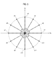
- Figure 5 is a schematic diagram showing an example of locating the plurality of ultrasound data corresponding to a tissue on the complex plane, wherein the tissue moves at constant speed within the target object.
- Figure 6 is a schematic diagram showing an example of locating the plurality of ultrasound data corresponding to tissues on the complex plane, wherein the tissues comprise a tissue that does not move within the target object and a tissue that moves at constant speed within the target object.
- Figure 7 is a schematic diagram showing an example of locating a plurality of ultrasound data corresponding to a tissue on the complex plane, wherein the tissue moves at a lower speed than a predetermined speed within the target object.
- Figure 8 is a schematic diagram showing an example of locating the plurality of ultrasound data corresponding to the tissue and the blood flow on the complex plane, wherein the tissue moves at the constant speed within the target object.
- Figure 9 is a schematic diagram showing an example of locating the plurality of ultrasound data corresponding to the tissues and the blood flow on the complex plane, wherein the tissues comprise the tissue that does not move within the target object and the tissue that moves at the constant speed.
- Figure 10 is a schematic diagram showing an example of locating the plurality ultrasound data corresponding to the tissue and the blood flow, wherein the tissue moves at a low speed within the target object.
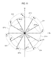
- Figure 11 is a schematic diagram showing an example of performing a circle fitting upon the plurality of ultrasound data corresponding to the tissue and the blood flow, wherein the tissue moves at the constant speed within the target object.
- Figure 12 is a schematic diagram showing an example of performing the circle fitting upon the plurality of ultrasound data corresponding to the tissues and the blood flow, wherein the tissues comprise the tissue that does not move within the target object and the tissue that moves at the constant speed within the target object.
- Figure 13 is a schematic diagram showing an example of performing the circle fitting upon the plurality of ultrasound data corresponding to the tissue and the blood flow, wherein the tissue moves at the low speed within the target object.
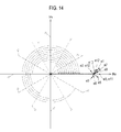
- Figure 14 is a schematic diagram showing an example of performing a downmixing upon the plurality of ultrasound data corresponding to the tissue and the blood flow, wherein the tissue moves at the constant speed.
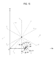
- Figure 15 is a schematic diagram showing an example of performing the downmixing upon the plurality of ultrasound data corresponding to the tissues and the blood flow, wherein the tissues comprise the tissue that does not move within the target object and the tissue that moves at the constant speed within the target object.
- Figure 16 is a schematic diagram showing an example of performing the downmixing upon the plurality of ultrasound data corresponding to the tissue and the blood flow, wherein the tissue moves at the low speed within the target object.
- Doppler mode comprises a color Doppler mode.
- FIG. 1 is a block diagram showing an illustrative embodiment of an ultrasound system.
- the ultrasound system 100 may include a user input unit 110, an ultrasound data acquisition unit 120, a processing unit 130, a storage unit 140 and a display unit 150.
- the user input unit 110 may be configured to receive input information from a user.
- the input information may include position and size information of a region of interest (ROI) 220, which may be set on a brightness mode image 210, as shown in Figure 2 .
- the ROI 220 may include a color box. Also, at least one of scan-lines may be comprised within the ROI 220.
- the user input unit 110 may include a control panel, a keyboard, a mouse and the like.
- the ultrasound data acquisition unit 120 may be configured to transmit and receive ultrasound signals to and from a target object to thereby acquire ultrasound data corresponding to the ROI (i.e., color box).
- the ultrasound data acquisition unit 120 will be described with reference to Figure 3 .
- FIG. 3 is a block diagram showing an illustrative embodiment of the ultrasound data acquisition unit.
- the ultrasound data acquisition unit 120 may include a transmit (Tx) signal generating section 121, an ultrasound probe 122 comprising a plurality of transducer elements (not shown), a beam former 123 and an ultrasound data forming section 124.
- the Tx signal generating section 121 may be configured to generate Tx signals in consideration of focal points and positions of the transducer elements.
- the Tx signals may be signals for acquiring a Doppler mode image.
- the Tx signal generating section 121 may generate a plurality of Tx signals based on a predetermined ensemble number.
- the ensemble number may represent the number of transmitting and receiving the ultrasound signals in order to acquire Doppler signals corresponding to a scan-line.
- the ultrasound probe 122 may be configured to convert the Tx signals provided from the Tx signal generating section 121 into the ultrasound signals.
- the ultrasound probe 122 may further transmit the ultrasound signals into the target object, and receive ultrasound echo signals reflected from the target object to thereby form received signals, which may be analog signals.
- the ultrasound probe 122 may include a linear array probe, a convex array probe and the like.
- the beam former 123 may be configured to convert the received signals provided from the ultrasound probe 122 into digital signals.
- the beam former 123 may further receive-focus the digital signals in consideration of the focal points and the positions of the transducer elements to thereby form receive-focused signals.
- the ultrasound data forming section 124 may be configured to form the ultrasound data based on the receive-focused signals provided from the beam former 123.
- the ultrasound data may include IQ (in-phase/quadrature) data (i.e., ensemble data) for acquiring the Doppler signals.
- the ultrasound data forming section 124 may form a plurality of ultrasound data corresponding to the ensemble number based on the receive-focused signals sequentially provided from the beam former 123.
- the processing unit 130 may be coupled to the user input unit 110 and the ultrasound data acquisition unit 120.
- the processing unit 130 may be configured to adaptively perform clutter filtering upon the ultrasound data provided from the ultrasound data acquisition unit 120.
- the processing unit 120 may further form the Doppler mode image based on the clutter-filtered ultrasound data.
- the processing unit 130 will be described in detail with reference to Figure 4 .
- FIG. 4 is a block diagram showing an illustrative embodiment of the processing unit.
- the processing unit 130 may include a data processing section 131, a circle fitting section 132, a center point detecting section 133, a determining section 134, a filtering section 135 and an image forming section 136.
- the data processing section 131 may be configured to analyze the plurality of ultrasound data (i.e., ensemble data) provided from the ultrasound data acquisition unit 120 to thereby locate each of the plurality of ultrasound data on a complex plane.
- the plurality of ultrasound data i.e., ensemble data
- the ultrasound data (i.e., ensemble data) corresponding to the ROI may be located on the complex plane in various shapes according to speeds of a tissue (e.g., vessel wall), blood flow and the like, which exist within the target object.
- tissue e.g., vessel wall
- blood flow e.g., blood flow
- Figure 5 is a schematic diagram showing an example of locating the plurality of ultrasound data corresponding to a tissue on the complex plane, wherein the tissue moves at a constant speed within the target object.
- a plurality of ultrasound data e1 to e12 acquired from the tissue may be located on a circumference with a center point at an origin O of the complex plane.
- the plurality of ultrasound data e1 to e12 may be located on the circumference at constant interval ⁇ .
- FIG. 6 is a schematic diagram showing an example of locating the plurality of ultrasound data corresponding to tissues on the complex plane, wherein the tissues comprise a tissue that does not move within the target object and another tissue that moves at constant speed within the target object.
- a plurality of ultrasound data e1 to e12 acquired from the tissues may be located on a circumference with a speed component (i.e., DC component) of the tissue that does not move within the target object as a center point C apart from the origin O of the complex plane.
- the plurality of ultrasound data e1 to e12 may be located on the circumference at the constant interval ⁇ .
- FIG. 7 is a schematic diagram showing an example of locating a plurality of ultrasound data corresponding to a tissue on the complex plane, wherein the tissue moves at a lower speed (hereinafter, "a low speed") than a predetermined speed within the target object.
- a low speed a lower speed
- the ultrasound data e1 to e3 acquired from the tissue may be located on a circumference CI1
- the ultrasound data e4 to e6 acquired from the tissue may be located on a circumference CI2
- the ultrasound data e7 to e9 acquired from the tissue may be located on a circumference CI3
- the ultrasound data e10 to e12 acquired from the tissue may be located on a circumference CI4.
- Center points C31 to C34 of the circumferences CI1 to CI4 may not be located on the origin O of the complex plane, and may move slowly.
- Figure 8 is a schematic diagram showing an example of locating the plurality of ultrasound data, which correspond to the tissue and the blood flow, on the complex plane, wherein the tissue moves at the constant speed within the target object.
- the data processing section 131 may be configured to analyze the plurality of ultrasound data e1 to e12 acquired from the tissue and the blood flow.
- the data processing section 131 may further locate the plurality of ultrasound data e1 to e12, which overlap speed components (shown by dotted lines) corresponding to the tissue with speed components (shown by lines) corresponding to the blood flow, on the complex plane as shown in Figure 8 .
- the plurality of ultrasound data e1 to e12 may be located on the complex plane with the center point at the origin O of the complex plane. In one embodiment, the overlap may represent sum of phases.
- Figure 9 is a schematic diagram showing an example of locating the plurality of ultrasound data corresponding to the tissues and the blood flow on the complex plane, wherein the tissues comprise the tissue that does not move within the target object and the tissue that moves at the constant speed.
- the data processing section 131 may be configured to analyze the plurality of ultrasound data e1 to e12 acquired from the tissues and the blood flow.
- the data processing section 131 may further locate the plurality of ultrasound data e1 to e12, which overlap speed components (shown by dotted lines) corresponding to the tissue with speed components (shown by lines) corresponding to the blood flow, on the complex plane as shown in Figure 9 .
- the plurality of ultrasound data may be located on the complex plane with the speed component (i.e., DC component) of the tissue that does not move within the target object as the center point C apart from the origin O of the complex plane.
- the speed component i.e., DC component
- Figure 10 is a schematic diagram showing an example of locating the plurality ultrasound data corresponding to the tissue and the blood flow, wherein the tissue moves at a low speed within the target object.
- the data processing section 131 may be configured to analyze the plurality of ultrasound data e1 to e12 acquired from the tissue and the blood flow.
- the data processing section 131 may further locate the plurality of ultrasound data e1 to e12, which overlap speed components (shown by dotted lines) corresponding to the tissue with speed components (shown by lines) corresponding to the blood flow, on the complex plane with the center points C31 to C34 as shown in Figure 10 .
- the circle fitting section 132 may be configured to form a plurality of ultrasound data group based on the plurality of ultrasound data located on the complex plane by the data processing section 131.
- Each of the ultrasound data groups may include a predetermined number of ultrasound data.
- the circle fitting section 132 may further perform a circle fitting upon each of the ultrasound data groups.
- the methods of performing the circle fitting are well known in the art.
- the circle fitting may include RANSAC circle fitting, a least-square circle fitting, an S-parameter circle fitting and the like.
- Figure 11 is a schematic diagram showing an example of performing the circle fitting upon the plurality of ultrasound data corresponding to the tissue and the blood flow, wherein the tissue moves at the constant speed within the target object.
- the circle fitting section 132 may be configured to group the plurality of ultrasound data e1 to e12 located on the complex plane as shown in Figure 8 into the plurality of ultrasound data group G11 to G14 as shown in Figure 11 .
- Each of the ultrasound data group G11 to G14 may include three ultrasound data.
- a first ultrasound data group G11 may include ultrasound data e1 to e3
- a second ultrasound data group G12 may include ultrasound data e4 to e6
- a third ultrasound data group G 13 may include ultrasound data e7 to e9
- a fourth ultrasound data group G14 may include ultrasound data e10 to e12.
- the circle fitting section 132 may further perform the circle fitting upon the ultrasound data corresponding to each of the ultrasound data group G11 to G14 to thereby set circumferences CF11 to CF14 corresponding to each of the ultrasound data group as shown in Figure 11 .
- Figure 12 is a schematic diagram showing an example of performing the circle fitting upon the plurality of ultrasound data corresponding to the tissues and the blood flow, wherein the tissues comprise the tissue that does not move within the target object and the tissue that moves at the constant speed within the target object.
- the circle fitting section 132 may be configured to group the plurality of ultrasound data e1 to e12 located on the complex plane as shown in Figure 9 into a plurality of ultrasound data groups G21 to G24 as shown in Figure 12 .
- Each of the ultrasound data groups G21 to G24 may include three ultrasound data.
- a first ultrasound data group G21 may include the ultrasound data e1 to e3
- a second ultrasound data group G22 may include the ultrasound data e4 to e6
- a third ultrasound data group G23 may include the ultrasound data e7 to e9
- the fourth ultrasound data group G24 may include the ultrasound data e10 to e12.
- the circle fitting section 132 may further perform the circle fitting upon the ultrasound data corresponding to each of the ultrasound data groups G21 to G24 to thereby set circumferences CF21 to CF24 corresponding to each of the ultrasound data groups G21 to G24 as shown in Figure 12 .
- Figure 13 is a schematic diagram showing an example of performing the circle fitting upon the plurality of ultrasound data corresponding to the tissue and the blood flow, wherein the tissue moves at the low speed within the target object.
- the circle fitting section 132 may be configured to group the plurality of ultrasound data e1 to e12 located on the complex plane as shown in Figure 10 into a plurality of ultrasound data groups G31 to G34 as shown in Figure 13 .
- Each of the ultrasound data groups G31 to G34 may include three ultrasound data. That is, a first ultrasound data may include the ultrasound data e1 to e3, a second ultrasound data may include the ultrasound data e4 to e6, a third ultrasound data may include the ultrasound data e7 to e9, and a fourth ultrasound data may include the ultrasound data e10 to e12.
- the circle fitting section 132 may further perform the circle fitting upon the ultrasound data corresponding to each of the ultrasound data groups G31 to G34 to thereby set circumferences CF31 to CF34 corresponding to each of the ultrasound data groups G31 to G34 as shown in Figure 13 .
- the center point detecting section 133 may be configured to detect center points of the circumferences corresponding to the plurality of ultrasound data groups based on the circumferences set by the circle fitting section 132.
- the center point detecting section 133 may detect center points C11 to C 14 of each of the circumferences CF11 to CF 14 corresponding to the plurality of ultrasound data groups G11 to G14 as shown in Figure 11 .
- the center point detecting section 133 may detect center points C21 to C24 of each of the circumferences CF21 to CF24 corresponding to the plurality of ultrasound data groups G21 to G24 as shown in Figure 12 .
- the center point detecting section 133 may detect center points C31 to C34 of each of the circumferences CF31 to CF34 corresponding to the plurality of ultrasound data groups G31 to G34 as shown in Figure 13 .
- the methods of detecting the center points are well known in the art. Thus, they have not been described in detail so as not to unnecessarily obscure the present disclosure.
- the determining section 134 may be configured to analyze the plurality of center points detected by the center point detecting section 133. The determining section 134 may further determine whether the plurality of the center points are located on the same position and whether located on the origin of the complex plane to thereby form determination information.
- the determining section 134 may be configured to analyze the center points C 11 to C 14 corresponding to the plurality of circumferences CF 11 to CF14 as shown in Figure 11 .
- the determining section 134 may further determine whether the plurality of center points C1 to C14 are located on the same position and whether located on the origin of the complex plane. If it is determined that the plurality of center points C11 to C14 are located on the same position and located on the origin of the complex plane, then the determining section 134 may form first determination information.
- the first determination information may be the information representing that the plurality of center points C11 to C 14 are located on the same position and located on the origin of the complex plane. That is, the first determination information may be information representing that the tissue and the blood flow exist within the target object, wherein the tissue moves at the constant speed.
- the determining section 134 may be configured to analyze the center points C21 to C24 corresponding to the plurality of circumferences CF21 to CF24 as shown in Figure 12 .
- the determining section 134 may further determine whether the plurality of center points C21 to C24 are located on the same position and whether located on the origin of the complex plane. If it is determined that the plurality of center points C21 to C24 are located on the same position but not located on the origin of the complex plane, then the determining section 134 may form second determination information.
- the second determination information may be the information representing that the plurality of center points C21 to C24 are located on the same position but not located on the origin of the complex plane. That is, the second determination information may be the information representing that the tissues and the blood flow exist within the target object, wherein the tissues comprise the tissue that does not move and the tissue that moves at the constant speed.
- the determining section 134 may be configured to analyze the center points C31 to C34 corresponding to the plurality of the circumferences CF31 to CF34 shown in Figure 13 .
- the determining section 134 may further determine whether the plurality of center points C31 to C34 are located on the same position and whether located on the origin of the complex plane. If it is determined that the plurality of center points C31 to C34 are neither located on the same position nor on the origin of the complex plane, then the determining section 134 may form third determination information.
- the third determination information may be the information representing that the plurality of center points C31 to C34 are neither located on the same position nor on the origin of the complex plane. That is, the third determination information may be the information representing that the tissue and the blood flow exist within the target object, wherein the tissue moves at the low speed.
- the filtering section 135 may be configured to perform a downmixing and a clutter filtering upon the plurality of ultrasound data based on the determination information provided from the determining section 134.
- Figure 14 is a schematic diagram showing an example of performing the downmixing upon the plurality of ultrasound data corresponding to the tissue and the blood flow, wherein the tissue moves at the constant speed.
- the filtering section 135 may be configured to perform the downmixing, which rotates each of the plurality of ultrasound data e1 to e12 into a real axis of the complex plane with the center point at the origin O of the complex plane based on the first determination information provided from the determining section 134, upon the plurality of ultrasound data e1 to e12 as shown in Figure 14 . More particularly, the filtering section 135 may perform the downmixing, which performs a phase shift (0°) upon the ultrasound data e1 based on the first determination information.
- the filtering section 135 may further perform the downmixing, which performs a phase shift (- ⁇ ) upon the ultrasound data e2 based on the first determination information.
- the filtering section 135 may further perform the downmixing, which performs a phase shift (-2 ⁇ ) upon the ultrasound data e3 based on the first determination information.
- the filtering section 135 may further perform the downmixing on the ultrasound data e4 to e12 as described above.
- the speed components corresponding to clutter signals moves to DC component.
- the filtering section 135 may further perform the clutter filtering upon the downmixed ultrasound data to thereby filter the speed components (i.e., DC component) corresponding to the clutter signals from the downmixed ultrasound data.
- Figure 15 is a schematic diagram showing an example of performing the downmixing upon the plurality of ultrasound data corresponding to the tissues and the blood flow, wherein the tissues comprise the tissue that does not move within the target object and the tissue that moves at the constant speed within the target object.
- the filtering section 135 may be configured to perform the downmixing upon each of the plurality of ultrasound data e1 to e12 based on the second determination information provided from the determining section 134 as shown in Figure 15 . More particularly, the filtering section 135 may move the center points of the circumferences corresponding to the ultrasound data e1 to e12 to the origin O of the complex plane based on the second determination information.
- the filtering section 135 may further perform the downmixing, which rotates each of the plurality of ultrasound data e1 to e12 into the real axis based on the origin O of the complex plane as described above. That is, the filtering section 135 may perform the downmixing, which performs a phase shift (0°) on the ultrasound data e1 based on the second determination information. The filtering section 135 may further perform the downmixing, which performs a phase shift (- ⁇ ) on the ultrasound data e2 based on the second determination information. The filtering section 135 may further perform the downmixing, which performs a phase shift (-2 ⁇ ) on the ultrasound data e3 based on the second determination information.
- the filtering section 135 may further perform the downmixing on the ultrasound data e4 to e12 as described above. As to performing the downmixing upon each of the plurality of ultrasound data, the speed components corresponding to clutter signals move to DC component. The filtering section 135 may further perform the clutter filtering upon the downmixed ultrasound data to thereby filter the speed components (i.e., DC component) corresponding to the clutter signals from the plurality of the ultrasound data.
- the filtering section 135 may move the center points of the circumferences corresponding to the plurality of ultrasound data to the origin of the complex plane, and perform the downmixing on each of the ultrasound data.
- the filtering section 135 may further set any ultrasound data (e.g., first ultrasound data e1) among the plurality of ultrasound data e1 to e12 as a reference ultrasound data, perform the downmixing, which rotates each of the ultrasound data into the reference ultrasound data, upon the plurality of ultrasound data, and move the center points of the circumferences to the origin of the complex plane.
- Figure 16 is a schematic diagram showing an example of performing the downmixing upon the plurality of ultrasound data corresponding to the tissue and the blood flow, wherein the tissue moves at the low speed within the target object.
- the filtering section 135 may be configured to perform the downmixing upon each of the ultrasound data e1 to e12 based on the third determination information provided from the determining section 134 as shown in Figure 16 . More particularly, the filtering section 135 may move the center points of the plurality of circumferences corresponding to the plurality of ultrasound data e1 to e12 to the origin O of the complex plane based on the third determination information.
- the filtering section 135 may further perform the downmixing that rotates each of the ultrasound data e1 to e12 into the real axis of the complex plane based on the origin O of the complex plane as described above. As to performing the downmixing on each of the ultrasound data, the speed components corresponding to clutter signals move to the DC component. The filtering section 135 may further perform the clutter filtering on the plurality of ultrasound data to thereby filter the speed components (i.e., DC component) corresponding to the clutter signals from the plurality of the ultrasound data.
- the speed components i.e., DC component
- the image forming section 136 may be configured to form a Doppler mode image based on the plurality of ultrasound image downmixed and clutter-filtered by the filtering section 135.
- the storage unit 140 may store the plurality of ultrasound data acquired from the ultrasound data acquisition unit 110.
- the storage unit 140 may further store the plurality of ultrasound data filtered by the processing unit 130.
- the display unit 150 may display the Doppler mode image formed by the processing unit 130.
- the processing unit 130 may perform the circle fitting, the downmixing and the clutter filtering upon the plurality of ultrasound data acquired from the ultrasound data acquisition unit 120, the processing unit 130 may further perform the circle fitting, the downmixing and the clutter filtering on a plurality of ultrasound data provided from external devices (e.g., a personal computer, a storage medium, etc.) which connect to the ultrasound system.
- external devices e.g., a personal computer, a storage medium, etc.
Landscapes
- Engineering & Computer Science (AREA)
- Physics & Mathematics (AREA)
- Health & Medical Sciences (AREA)
- Radar, Positioning & Navigation (AREA)
- Remote Sensing (AREA)
- Life Sciences & Earth Sciences (AREA)
- Acoustics & Sound (AREA)
- Nuclear Medicine, Radiotherapy & Molecular Imaging (AREA)
- Heart & Thoracic Surgery (AREA)
- Biophysics (AREA)
- Computer Networks & Wireless Communication (AREA)
- Pathology (AREA)
- Radiology & Medical Imaging (AREA)
- Biomedical Technology (AREA)
- General Physics & Mathematics (AREA)
- Medical Informatics (AREA)
- Molecular Biology (AREA)
- Surgery (AREA)
- Animal Behavior & Ethology (AREA)
- General Health & Medical Sciences (AREA)
- Public Health (AREA)
- Veterinary Medicine (AREA)
- Ultra Sonic Daignosis Equipment (AREA)
Applications Claiming Priority (2)
| Application Number | Priority Date | Filing Date | Title |
|---|---|---|---|
| KR20090038060 | 2009-04-30 | ||
| KR20100034064A KR101193710B1 (ko) | 2009-04-30 | 2010-04-14 | 적응적 클러터 필터링을 수행하는 초음파 시스템 및 방법 |
Publications (3)
| Publication Number | Publication Date |
|---|---|
| EP2248468A2 true EP2248468A2 (de) | 2010-11-10 |
| EP2248468A3 EP2248468A3 (de) | 2013-05-29 |
| EP2248468B1 EP2248468B1 (de) | 2014-07-02 |
Family
ID=42358515
Family Applications (1)
| Application Number | Title | Priority Date | Filing Date |
|---|---|---|---|
| EP10160837.0A Not-in-force EP2248468B1 (de) | 2009-04-30 | 2010-04-23 | Ultraschallsystem und -Verfahren für adaptive Clutter Filterung |
Country Status (3)
| Country | Link |
|---|---|
| US (1) | US8545411B2 (de) |
| EP (1) | EP2248468B1 (de) |
| JP (1) | JP5593116B2 (de) |
Families Citing this family (6)
| Publication number | Priority date | Publication date | Assignee | Title |
|---|---|---|---|---|
| JP5513976B2 (ja) * | 2010-05-12 | 2014-06-04 | 株式会社東芝 | 超音波診断装置 |
| KR101313220B1 (ko) | 2010-11-23 | 2013-09-30 | 삼성메디슨 주식회사 | 특성 곡선 정보에 기초하여 컬러 도플러 모드 영상을 제공하는 초음파 시스템 및 방법 |
| WO2014142174A1 (ja) * | 2013-03-12 | 2014-09-18 | 株式会社 東芝 | 超音波診断装置及び超音波画像処理方法 |
| US10079647B2 (en) | 2014-12-10 | 2018-09-18 | Nxp Usa, Inc. | DC offset calibration of wireless receivers |
| US9444661B2 (en) | 2015-01-23 | 2016-09-13 | Freescale Semiconductor, Inc. | DC offset tracking of wireless receivers |
| US9608587B2 (en) | 2015-06-25 | 2017-03-28 | Freescale Semiconductor, Inc. | Systems and methods to dynamically calibrate and adjust gains in a direct conversion receiver |
Family Cites Families (16)
| Publication number | Priority date | Publication date | Assignee | Title |
|---|---|---|---|---|
| US4932415A (en) * | 1988-11-14 | 1990-06-12 | Vingmed Sound A/S | Method of color coding two dimensional ulltrasonic doppler velocity images of blood flow on a display |
| US5197477A (en) * | 1990-10-12 | 1993-03-30 | Advanced Technology Laboratories, Inc. | Ultrasonic doppler flow measurement system with tissue motion discrimination |
| US5226420A (en) * | 1991-06-07 | 1993-07-13 | Advanced Technology Laboratories, Inc. | Ultrasonic color flow imaging using autoregressive processing |
| JP3093823B2 (ja) * | 1991-07-02 | 2000-10-03 | フクダ電子株式会社 | 超音波ドプラ診断装置 |
| JP2720711B2 (ja) * | 1992-06-04 | 1998-03-04 | 松下電器産業株式会社 | 超音波二次元ドプラ血流計 |
| JPH06254095A (ja) * | 1993-03-08 | 1994-09-13 | Fujitsu Ltd | 複素mtiフィルタ |
| JP2723458B2 (ja) * | 1993-12-24 | 1998-03-09 | アロカ株式会社 | 超音波ドプラ診断装置 |
| JP3946288B2 (ja) * | 1996-10-01 | 2007-07-18 | 東芝医用システムエンジニアリング株式会社 | 超音波カラードプラ診断装置および超音波カラードプライメージングの信号処理方法 |
| JP4149554B2 (ja) * | 1998-03-25 | 2008-09-10 | 株式会社東芝 | 超音波ドプラ診断装置 |
| KR100352638B1 (ko) | 1999-05-06 | 2002-09-18 | 주식회사 메디슨 | 초음파 칼라 도플러 영상 시스템을 위한 클러터신호 필터링방법 및 장치 |
| JP2004195228A (ja) | 2002-12-18 | 2004-07-15 | Koninkl Philips Electronics Nv | 最適化された送信シーケンスを用いた超音波撮像における適応フィルタリング |
| US7942821B2 (en) * | 2003-11-27 | 2011-05-17 | Hitachi Medical Corporation | Doppler velocity detection device and ultrasonographic device using the same |
| JP4504004B2 (ja) * | 2003-12-17 | 2010-07-14 | 株式会社東芝 | 超音波診断装置 |
| US7831398B2 (en) * | 2007-12-20 | 2010-11-09 | Expro Meters, Inc. | Method for quantifying varying propagation characteristics of normal incident ultrasonic signals as used in correlation based flow measurement |
| JP2008149153A (ja) | 2008-01-07 | 2008-07-03 | Toshiba Corp | 超音波ドプラ診断装置 |
| JP2011519288A (ja) * | 2008-04-03 | 2011-07-07 | カイ メディカル、 インコーポレイテッド | 非接触の生理的運動センサおよびその使用方法 |
-
2010
- 2010-04-23 EP EP10160837.0A patent/EP2248468B1/de not_active Not-in-force
- 2010-04-23 JP JP2010100289A patent/JP5593116B2/ja not_active Expired - Fee Related
- 2010-04-30 US US12/772,088 patent/US8545411B2/en not_active Expired - Fee Related
Non-Patent Citations (1)
| Title |
|---|
| None |
Also Published As
| Publication number | Publication date |
|---|---|
| US8545411B2 (en) | 2013-10-01 |
| JP5593116B2 (ja) | 2014-09-17 |
| EP2248468A3 (de) | 2013-05-29 |
| JP2010259790A (ja) | 2010-11-18 |
| US20100280386A1 (en) | 2010-11-04 |
| EP2248468B1 (de) | 2014-07-02 |
Similar Documents
| Publication | Publication Date | Title |
|---|---|---|
| CN110192893B (zh) | 量化超声成像的感兴趣区域放置 | |
| US11238562B2 (en) | Ultrasound system with deep learning network for image artifact identification and removal | |
| EP2016905B1 (de) | Diagnostische Ultraschallvorrichtung | |
| US8864671B2 (en) | Methods and systems for color flow imaging | |
| US9261485B2 (en) | Providing color doppler image based on qualification curve information in ultrasound system | |
| EP2289420B1 (de) | Einstellung eines optimalen Bildparameters in einem Ultraschallsystem | |
| US9069062B2 (en) | Surface rendering for volume data in an ultrasound system | |
| EP2248468A2 (de) | Ultraschallsystem und Verfahren mit adaptiven Clutterfilter | |
| EP3579757B1 (de) | Ultraschallauswertung von anatomischen merkmalen | |
| KR20170035796A (ko) | 초음파 컬러 흐름에서의 스파클 아티팩트 검출 | |
| EP2264483B1 (de) | Ultraschallsystem und Verfahren zur Bereitstellung eines Bewegungsvektors | |
| EP2610635A2 (de) | Erstellung von spektralen Doppler Bildern, die mindestens zwei Probenvolumen entsprechen | |
| KR20080090888A (ko) | 초음파 영상을 형성하는 초음파 시스템 및 방법 | |
| JP2016508429A (ja) | カーソルポインタ制御を備えたハンドヘルド医用撮像装置 | |
| EP2610641A2 (de) | Ultraschall und System zum Erzeugen von Doppler Ultraschallbildern | |
| US20210077075A1 (en) | Ultrasound image processing | |
| US9078590B2 (en) | Providing additional information corresponding to change of blood flow with a time in ultrasound system | |
| EP2392945A2 (de) | Bereitstellung eines bewegten Bildes in einem Ultraschallsystem | |
| KR101193710B1 (ko) | 적응적 클러터 필터링을 수행하는 초음파 시스템 및 방법 | |
| JP2021529035A (ja) | 経弁圧の定量化を行うための方法及びシステム | |
| EP3274959B1 (de) | Optimale ultraschallbasierte organsegmentierung | |
| EP4666956A1 (de) | Benutzerschnittstelle für ultraschallbildgebungssystem zur auswahl eines bestimmten gefässes | |
| WO2025261880A1 (en) | Ultrasound imaging system user interface for selecting a vessel of interest | |
| KR20140068828A (ko) | 송신 지연을 이용하여 벡터 정보를 검출하는 초음파 시스템 및 방법 | |
| Bennett | Signal processing techniques for ultrasonic tissue doppler and real-time B-mode imaging in cardiology |
Legal Events
| Date | Code | Title | Description |
|---|---|---|---|
| PUAI | Public reference made under article 153(3) epc to a published international application that has entered the european phase |
Free format text: ORIGINAL CODE: 0009012 |
|
| AK | Designated contracting states |
Kind code of ref document: A2 Designated state(s): AT BE BG CH CY CZ DE DK EE ES FI FR GB GR HR HU IE IS IT LI LT LU LV MC MK MT NL NO PL PT RO SE SI SK SM TR |
|
| AX | Request for extension of the european patent |
Extension state: AL BA ME RS |
|
| PUAL | Search report despatched |
Free format text: ORIGINAL CODE: 0009013 |
|
| AK | Designated contracting states |
Kind code of ref document: A3 Designated state(s): AT BE BG CH CY CZ DE DK EE ES FI FR GB GR HR HU IE IS IT LI LT LU LV MC MK MT NL NO PL PT RO SE SI SK SM TR |
|
| AX | Request for extension of the european patent |
Extension state: AL BA ME RS |
|
| RIC1 | Information provided on ipc code assigned before grant |
Ipc: G01S 15/89 20060101ALI20130423BHEP Ipc: A61B 8/00 20060101AFI20130423BHEP |
|
| 17P | Request for examination filed |
Effective date: 20131129 |
|
| RBV | Designated contracting states (corrected) |
Designated state(s): AT BE BG CH CY CZ DE DK EE ES FI FR GB GR HR HU IE IS IT LI LT LU LV MC MK MT NL NO PL PT RO SE SI SK SM TR |
|
| GRAP | Despatch of communication of intention to grant a patent |
Free format text: ORIGINAL CODE: EPIDOSNIGR1 |
|
| RIC1 | Information provided on ipc code assigned before grant |
Ipc: G01S 15/89 20060101ALI20140123BHEP Ipc: A61B 8/00 20060101AFI20140123BHEP |
|
| INTG | Intention to grant announced |
Effective date: 20140206 |
|
| GRAS | Grant fee paid |
Free format text: ORIGINAL CODE: EPIDOSNIGR3 |
|
| GRAA | (expected) grant |
Free format text: ORIGINAL CODE: 0009210 |
|
| AK | Designated contracting states |
Kind code of ref document: B1 Designated state(s): AT BE BG CH CY CZ DE DK EE ES FI FR GB GR HR HU IE IS IT LI LT LU LV MC MK MT NL NO PL PT RO SE SI SK SM TR |
|
| REG | Reference to a national code |
Ref country code: GB Ref legal event code: FG4D |
|
| REG | Reference to a national code |
Ref country code: CH Ref legal event code: EP Ref country code: AT Ref legal event code: REF Ref document number: 675465 Country of ref document: AT Kind code of ref document: T Effective date: 20140715 |
|
| REG | Reference to a national code |
Ref country code: IE Ref legal event code: FG4D |
|
| RAP2 | Party data changed (patent owner data changed or rights of a patent transferred) |
Owner name: SAMSUNG MEDISON CO., LTD. |
|
| REG | Reference to a national code |
Ref country code: DE Ref legal event code: R096 Ref document number: 602010017157 Country of ref document: DE Effective date: 20140814 |
|
| RAP2 | Party data changed (patent owner data changed or rights of a patent transferred) |
Owner name: SAMSUNG MEDISON CO., LTD. |
|
| REG | Reference to a national code |
Ref country code: NL Ref legal event code: T3 |
|
| REG | Reference to a national code |
Ref country code: AT Ref legal event code: MK05 Ref document number: 675465 Country of ref document: AT Kind code of ref document: T Effective date: 20140702 |
|
| REG | Reference to a national code |
Ref country code: LT Ref legal event code: MG4D |
|
| REG | Reference to a national code |
Ref country code: DE Ref legal event code: R082 Ref document number: 602010017157 Country of ref document: DE Representative=s name: LORENZ & KOLLEGEN PATENTANWAELTE PARTNERSCHAFT, DE |
|
| PG25 | Lapsed in a contracting state [announced via postgrant information from national office to epo] |
Ref country code: SE Free format text: LAPSE BECAUSE OF FAILURE TO SUBMIT A TRANSLATION OF THE DESCRIPTION OR TO PAY THE FEE WITHIN THE PRESCRIBED TIME-LIMIT Effective date: 20140702 Ref country code: NO Free format text: LAPSE BECAUSE OF FAILURE TO SUBMIT A TRANSLATION OF THE DESCRIPTION OR TO PAY THE FEE WITHIN THE PRESCRIBED TIME-LIMIT Effective date: 20141002 Ref country code: PT Free format text: LAPSE BECAUSE OF FAILURE TO SUBMIT A TRANSLATION OF THE DESCRIPTION OR TO PAY THE FEE WITHIN THE PRESCRIBED TIME-LIMIT Effective date: 20141103 Ref country code: LT Free format text: LAPSE BECAUSE OF FAILURE TO SUBMIT A TRANSLATION OF THE DESCRIPTION OR TO PAY THE FEE WITHIN THE PRESCRIBED TIME-LIMIT Effective date: 20140702 Ref country code: GR Free format text: LAPSE BECAUSE OF FAILURE TO SUBMIT A TRANSLATION OF THE DESCRIPTION OR TO PAY THE FEE WITHIN THE PRESCRIBED TIME-LIMIT Effective date: 20141003 Ref country code: CZ Free format text: LAPSE BECAUSE OF FAILURE TO SUBMIT A TRANSLATION OF THE DESCRIPTION OR TO PAY THE FEE WITHIN THE PRESCRIBED TIME-LIMIT Effective date: 20140702 Ref country code: ES Free format text: LAPSE BECAUSE OF FAILURE TO SUBMIT A TRANSLATION OF THE DESCRIPTION OR TO PAY THE FEE WITHIN THE PRESCRIBED TIME-LIMIT Effective date: 20140702 Ref country code: BG Free format text: LAPSE BECAUSE OF FAILURE TO SUBMIT A TRANSLATION OF THE DESCRIPTION OR TO PAY THE FEE WITHIN THE PRESCRIBED TIME-LIMIT Effective date: 20141002 Ref country code: FI Free format text: LAPSE BECAUSE OF FAILURE TO SUBMIT A TRANSLATION OF THE DESCRIPTION OR TO PAY THE FEE WITHIN THE PRESCRIBED TIME-LIMIT Effective date: 20140702 |
|
| REG | Reference to a national code |
Ref country code: DE Ref legal event code: R081 Ref document number: 602010017157 Country of ref document: DE Owner name: SAMSUNG MEDISON CO., LTD., HONGCHEON-GUN, KR Free format text: FORMER OWNER: MEDISON CO., LTD., KANGWON, KR Effective date: 20140801 Ref country code: DE Ref legal event code: R082 Ref document number: 602010017157 Country of ref document: DE Representative=s name: LORENZ & KOLLEGEN PATENTANWAELTE PARTNERSCHAFT, DE Effective date: 20150107 Ref country code: DE Ref legal event code: R081 Ref document number: 602010017157 Country of ref document: DE Owner name: SAMSUNG MEDISON CO., LTD., HONGCHEON-GUN, KR Free format text: FORMER OWNER: SAMSUNG MEDISON CO., LTD., SEOUL, KR Effective date: 20150107 |
|
| PG25 | Lapsed in a contracting state [announced via postgrant information from national office to epo] |
Ref country code: HR Free format text: LAPSE BECAUSE OF FAILURE TO SUBMIT A TRANSLATION OF THE DESCRIPTION OR TO PAY THE FEE WITHIN THE PRESCRIBED TIME-LIMIT Effective date: 20140702 Ref country code: LV Free format text: LAPSE BECAUSE OF FAILURE TO SUBMIT A TRANSLATION OF THE DESCRIPTION OR TO PAY THE FEE WITHIN THE PRESCRIBED TIME-LIMIT Effective date: 20140702 Ref country code: CY Free format text: LAPSE BECAUSE OF FAILURE TO SUBMIT A TRANSLATION OF THE DESCRIPTION OR TO PAY THE FEE WITHIN THE PRESCRIBED TIME-LIMIT Effective date: 20140702 Ref country code: AT Free format text: LAPSE BECAUSE OF FAILURE TO SUBMIT A TRANSLATION OF THE DESCRIPTION OR TO PAY THE FEE WITHIN THE PRESCRIBED TIME-LIMIT Effective date: 20140702 Ref country code: PL Free format text: LAPSE BECAUSE OF FAILURE TO SUBMIT A TRANSLATION OF THE DESCRIPTION OR TO PAY THE FEE WITHIN THE PRESCRIBED TIME-LIMIT Effective date: 20140702 Ref country code: IS Free format text: LAPSE BECAUSE OF FAILURE TO SUBMIT A TRANSLATION OF THE DESCRIPTION OR TO PAY THE FEE WITHIN THE PRESCRIBED TIME-LIMIT Effective date: 20141102 |
|
| REG | Reference to a national code |
Ref country code: DE Ref legal event code: R097 Ref document number: 602010017157 Country of ref document: DE |
|
| PG25 | Lapsed in a contracting state [announced via postgrant information from national office to epo] |
Ref country code: RO Free format text: LAPSE BECAUSE OF FAILURE TO SUBMIT A TRANSLATION OF THE DESCRIPTION OR TO PAY THE FEE WITHIN THE PRESCRIBED TIME-LIMIT Effective date: 20140702 Ref country code: EE Free format text: LAPSE BECAUSE OF FAILURE TO SUBMIT A TRANSLATION OF THE DESCRIPTION OR TO PAY THE FEE WITHIN THE PRESCRIBED TIME-LIMIT Effective date: 20140702 Ref country code: DK Free format text: LAPSE BECAUSE OF FAILURE TO SUBMIT A TRANSLATION OF THE DESCRIPTION OR TO PAY THE FEE WITHIN THE PRESCRIBED TIME-LIMIT Effective date: 20140702 Ref country code: SK Free format text: LAPSE BECAUSE OF FAILURE TO SUBMIT A TRANSLATION OF THE DESCRIPTION OR TO PAY THE FEE WITHIN THE PRESCRIBED TIME-LIMIT Effective date: 20140702 |
|
| PLBE | No opposition filed within time limit |
Free format text: ORIGINAL CODE: 0009261 |
|
| STAA | Information on the status of an ep patent application or granted ep patent |
Free format text: STATUS: NO OPPOSITION FILED WITHIN TIME LIMIT |
|
| 26N | No opposition filed |
Effective date: 20150407 |
|
| PG25 | Lapsed in a contracting state [announced via postgrant information from national office to epo] |
Ref country code: SI Free format text: LAPSE BECAUSE OF FAILURE TO SUBMIT A TRANSLATION OF THE DESCRIPTION OR TO PAY THE FEE WITHIN THE PRESCRIBED TIME-LIMIT Effective date: 20140702 Ref country code: MC Free format text: LAPSE BECAUSE OF FAILURE TO SUBMIT A TRANSLATION OF THE DESCRIPTION OR TO PAY THE FEE WITHIN THE PRESCRIBED TIME-LIMIT Effective date: 20140702 Ref country code: LU Free format text: LAPSE BECAUSE OF FAILURE TO SUBMIT A TRANSLATION OF THE DESCRIPTION OR TO PAY THE FEE WITHIN THE PRESCRIBED TIME-LIMIT Effective date: 20150423 |
|
| REG | Reference to a national code |
Ref country code: CH Ref legal event code: PL |
|
| GBPC | Gb: european patent ceased through non-payment of renewal fee |
Effective date: 20150423 |
|
| REG | Reference to a national code |
Ref country code: IE Ref legal event code: MM4A |
|
| PG25 | Lapsed in a contracting state [announced via postgrant information from national office to epo] |
Ref country code: CH Free format text: LAPSE BECAUSE OF NON-PAYMENT OF DUE FEES Effective date: 20150430 Ref country code: GB Free format text: LAPSE BECAUSE OF NON-PAYMENT OF DUE FEES Effective date: 20150423 Ref country code: LI Free format text: LAPSE BECAUSE OF NON-PAYMENT OF DUE FEES Effective date: 20150430 |
|
| REG | Reference to a national code |
Ref country code: FR Ref legal event code: PLFP Year of fee payment: 7 |
|
| PG25 | Lapsed in a contracting state [announced via postgrant information from national office to epo] |
Ref country code: IE Free format text: LAPSE BECAUSE OF NON-PAYMENT OF DUE FEES Effective date: 20150423 |
|
| PG25 | Lapsed in a contracting state [announced via postgrant information from national office to epo] |
Ref country code: BE Free format text: LAPSE BECAUSE OF FAILURE TO SUBMIT A TRANSLATION OF THE DESCRIPTION OR TO PAY THE FEE WITHIN THE PRESCRIBED TIME-LIMIT Effective date: 20140702 |
|
| PG25 | Lapsed in a contracting state [announced via postgrant information from national office to epo] |
Ref country code: MT Free format text: LAPSE BECAUSE OF FAILURE TO SUBMIT A TRANSLATION OF THE DESCRIPTION OR TO PAY THE FEE WITHIN THE PRESCRIBED TIME-LIMIT Effective date: 20140702 |
|
| REG | Reference to a national code |
Ref country code: FR Ref legal event code: PLFP Year of fee payment: 8 |
|
| PG25 | Lapsed in a contracting state [announced via postgrant information from national office to epo] |
Ref country code: SM Free format text: LAPSE BECAUSE OF FAILURE TO SUBMIT A TRANSLATION OF THE DESCRIPTION OR TO PAY THE FEE WITHIN THE PRESCRIBED TIME-LIMIT Effective date: 20140702 Ref country code: HU Free format text: LAPSE BECAUSE OF FAILURE TO SUBMIT A TRANSLATION OF THE DESCRIPTION OR TO PAY THE FEE WITHIN THE PRESCRIBED TIME-LIMIT; INVALID AB INITIO Effective date: 20100423 |
|
| PG25 | Lapsed in a contracting state [announced via postgrant information from national office to epo] |
Ref country code: TR Free format text: LAPSE BECAUSE OF FAILURE TO SUBMIT A TRANSLATION OF THE DESCRIPTION OR TO PAY THE FEE WITHIN THE PRESCRIBED TIME-LIMIT Effective date: 20140702 |
|
| REG | Reference to a national code |
Ref country code: FR Ref legal event code: CA Effective date: 20170915 |
|
| REG | Reference to a national code |
Ref country code: FR Ref legal event code: PLFP Year of fee payment: 9 |
|
| PG25 | Lapsed in a contracting state [announced via postgrant information from national office to epo] |
Ref country code: MK Free format text: LAPSE BECAUSE OF FAILURE TO SUBMIT A TRANSLATION OF THE DESCRIPTION OR TO PAY THE FEE WITHIN THE PRESCRIBED TIME-LIMIT Effective date: 20140702 |
|
| PGFP | Annual fee paid to national office [announced via postgrant information from national office to epo] |
Ref country code: FR Payment date: 20190307 Year of fee payment: 10 |
|
| PGFP | Annual fee paid to national office [announced via postgrant information from national office to epo] |
Ref country code: NL Payment date: 20190306 Year of fee payment: 10 |
|
| PGFP | Annual fee paid to national office [announced via postgrant information from national office to epo] |
Ref country code: IT Payment date: 20190410 Year of fee payment: 10 Ref country code: DE Payment date: 20190305 Year of fee payment: 10 |
|
| REG | Reference to a national code |
Ref country code: DE Ref legal event code: R119 Ref document number: 602010017157 Country of ref document: DE |
|
| REG | Reference to a national code |
Ref country code: NL Ref legal event code: MM Effective date: 20200501 |
|
| PG25 | Lapsed in a contracting state [announced via postgrant information from national office to epo] |
Ref country code: DE Free format text: LAPSE BECAUSE OF NON-PAYMENT OF DUE FEES Effective date: 20201103 Ref country code: FR Free format text: LAPSE BECAUSE OF NON-PAYMENT OF DUE FEES Effective date: 20200430 |
|
| PG25 | Lapsed in a contracting state [announced via postgrant information from national office to epo] |
Ref country code: NL Free format text: LAPSE BECAUSE OF NON-PAYMENT OF DUE FEES Effective date: 20200501 |
|
| PG25 | Lapsed in a contracting state [announced via postgrant information from national office to epo] |
Ref country code: IT Free format text: LAPSE BECAUSE OF NON-PAYMENT OF DUE FEES Effective date: 20200423 |