EP2392945A2 - Bereitstellung eines bewegten Bildes in einem Ultraschallsystem - Google Patents
Bereitstellung eines bewegten Bildes in einem Ultraschallsystem Download PDFInfo
- Publication number
- EP2392945A2 EP2392945A2 EP11168038A EP11168038A EP2392945A2 EP 2392945 A2 EP2392945 A2 EP 2392945A2 EP 11168038 A EP11168038 A EP 11168038A EP 11168038 A EP11168038 A EP 11168038A EP 2392945 A2 EP2392945 A2 EP 2392945A2
- Authority
- EP
- European Patent Office
- Prior art keywords
- motion
- ultrasound
- data
- frame
- processing unit
- Prior art date
- Legal status (The legal status is an assumption and is not a legal conclusion. Google has not performed a legal analysis and makes no representation as to the accuracy of the status listed.)
- Withdrawn
Links
Images

Classifications
-
- G—PHYSICS
- G01—MEASURING; TESTING
- G01S—RADIO DIRECTION-FINDING; RADIO NAVIGATION; DETERMINING DISTANCE OR VELOCITY BY USE OF RADIO WAVES; LOCATING OR PRESENCE-DETECTING BY USE OF THE REFLECTION OR RERADIATION OF RADIO WAVES; ANALOGOUS ARRANGEMENTS USING OTHER WAVES
- G01S15/00—Systems using the reflection or reradiation of acoustic waves, e.g. sonar systems
- G01S15/88—Sonar systems specially adapted for specific applications
- G01S15/89—Sonar systems specially adapted for specific applications for mapping or imaging
- G01S15/8906—Short-range imaging systems; Acoustic microscope systems using pulse-echo techniques
- G01S15/8979—Combined Doppler and pulse-echo imaging systems
-
- G—PHYSICS
- G01—MEASURING; TESTING
- G01S—RADIO DIRECTION-FINDING; RADIO NAVIGATION; DETERMINING DISTANCE OR VELOCITY BY USE OF RADIO WAVES; LOCATING OR PRESENCE-DETECTING BY USE OF THE REFLECTION OR RERADIATION OF RADIO WAVES; ANALOGOUS ARRANGEMENTS USING OTHER WAVES
- G01S15/00—Systems using the reflection or reradiation of acoustic waves, e.g. sonar systems
- G01S15/88—Sonar systems specially adapted for specific applications
- G01S15/89—Sonar systems specially adapted for specific applications for mapping or imaging
- G01S15/8906—Short-range imaging systems; Acoustic microscope systems using pulse-echo techniques
- G01S15/8959—Short-range imaging systems; Acoustic microscope systems using pulse-echo techniques using coded signals for correlation purposes
- G01S15/8963—Short-range imaging systems; Acoustic microscope systems using pulse-echo techniques using coded signals for correlation purposes using pulse inversion
-
- G—PHYSICS
- G01—MEASURING; TESTING
- G01S—RADIO DIRECTION-FINDING; RADIO NAVIGATION; DETERMINING DISTANCE OR VELOCITY BY USE OF RADIO WAVES; LOCATING OR PRESENCE-DETECTING BY USE OF THE REFLECTION OR RERADIATION OF RADIO WAVES; ANALOGOUS ARRANGEMENTS USING OTHER WAVES
- G01S7/00—Details of systems according to groups G01S13/00, G01S15/00, G01S17/00
- G01S7/52—Details of systems according to groups G01S13/00, G01S15/00, G01S17/00 of systems according to group G01S15/00
- G01S7/52017—Details of systems according to groups G01S13/00, G01S15/00, G01S17/00 of systems according to group G01S15/00 particularly adapted to short-range imaging
- G01S7/52085—Details related to the ultrasound signal acquisition, e.g. scan sequences
- G01S7/52087—Details related to the ultrasound signal acquisition, e.g. scan sequences using synchronization techniques
- G01S7/52088—Details related to the ultrasound signal acquisition, e.g. scan sequences using synchronization techniques involving retrospective scan line rearrangements
-
- G—PHYSICS
- G01—MEASURING; TESTING
- G01S—RADIO DIRECTION-FINDING; RADIO NAVIGATION; DETERMINING DISTANCE OR VELOCITY BY USE OF RADIO WAVES; LOCATING OR PRESENCE-DETECTING BY USE OF THE REFLECTION OR RERADIATION OF RADIO WAVES; ANALOGOUS ARRANGEMENTS USING OTHER WAVES
- G01S7/00—Details of systems according to groups G01S13/00, G01S15/00, G01S17/00
- G01S7/52—Details of systems according to groups G01S13/00, G01S15/00, G01S17/00 of systems according to group G01S15/00
- G01S7/52017—Details of systems according to groups G01S13/00, G01S15/00, G01S17/00 of systems according to group G01S15/00 particularly adapted to short-range imaging
- G01S7/52023—Details of receivers
- G01S7/52036—Details of receivers using analysis of echo signal for target characterisation
- G01S7/52038—Details of receivers using analysis of echo signal for target characterisation involving non-linear properties of the propagation medium or of the reflective target
Definitions
- the present disclosure generally relates to ultrasound systems, and more particularly to providing a motion image in an ultrasound system.
- An ultrasound system has become an important and popular diagnostic tool since it has a wide range of applications. Specifically, due to its non-invasive and non-destructive nature, the ultrasound system has been extensively used in the medical profession. Modem high-performance ultrasound systems and techniques are commonly used to produce two-dimensional (2D) or three-dimensional (3D) ultrasound images of internal features of an object (e.g., human organs).
- 2D two-dimensional
- 3D three-dimensional
- the ultrasound system may provide ultrasound images of various modes including a brightness mode (B mode) image representing reflection coefficients of the ultrasound signals reflected from a target object of a living body with a 2D (two-dimensional) image, a Doppler mode (D mode) image representing speed of a moving object with spectral Doppler by using a Doppler effect, a color Doppler mode (C mode) image representing speed of a moving object with colors by using the Doppler effect, and an elastic mode (E mode) image representing mechanical characteristics of tissues object before and after applying a pressure thereto.
- the ultrasound system may transmit and receive ultrasound signals to and from the target object to thereby form Doppler signals corresponding to a region of interest (ROI), which is set on a B mode image.
- the ultrasound system may further form a C mode image that represents the speed of the moving object with colors based on the Doppler signals.
- the ultrasound system may transmit and receive ultrasound signals to and from the living body at a predetermined period to acquire ultrasound data corresponding to an ensemble number (i.e., ensemble data).
- the ultrasound system may further form the Doppler signals based on the ensemble data.
- the ultrasound system may also perform a wall filtering process to remove a component corresponding to a tissue, which does not move, upon the Doppler signals based on a wall filter to form the C mode image.
- a size of the ROI i.e., a color box
- the frame rate of the C mode image is decreased.
- an ultrasound system comprises: an ultrasound data acquisition unit configured to form transmit signals having different phases between a n th frame and a (n+1) th frame, transmit and receive ultrasound signals to and from a target object based on the transmit signals to output ultrasound data; and a processing unit in communication with the ultrasound data acquisition unit, the processing unit being configured to form motion data corresponding to a motion of the target object based on a phase difference between the ultrasound data corresponding to the n th frame and the ultrasound data corresponding to the (n+1) th frame, and form a motion image corresponding to the motion of the target object based on the motion data.
- a method of providing a motion image comprising: a) forming transmit signals having different phases between a n th frame and a (n+1) th frame; b) transmitting and receiving ultrasound signals to and from a target object based on the transmit signals to output ultrasound data; c) forming motion data corresponding to a motion of the target object based on a phase difference between the ultrasound data corresponding to the n th frame and the ultrasound data corresponding to the (n+1) th frame; and d) forming a motion image corresponding to the motion of the target object based on the motion data.
- a computer readable medium comprising computer executable instructions configured to perform the following acts: a) forming transmit signals having different phases between a n th frame and a (n+1) th frame; b) transmitting and receiving ultrasound signals to and from a target object based on the transmit signals to output ultrasound data; c) forming motion data corresponding to a motion of the target object based on a phase difference between the ultrasound data corresponding to the n th frame and the ultrasound data corresponding to the (n+1) th frame; and d) forming a motion image corresponding to the motion of the target object based on the motion data.
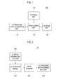
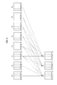
- an ultrasound system 100 in accordance with an illustrative embodiment is shown.
- the ultrasound system 100 includes an ultrasound data acquisition unit 110.
- the ultrasound data acquisition unit 110 is configured to transmit and receive ultrasound signals to and from a living body (not shown), and output ultrasound data.
- the living body includes a plurality of target objects (e.g., blood vessels, a heart, blood etc.).
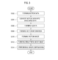
- FIG. 2 is a block diagram showing an illustrative embodiment of the ultrasound data acquisition unit 110.
- the ultrasound data acquisition unit 110 includes an ultrasound probe 210, a transmit (Tx) signal generating section 220, a beam former 230 and an ultrasound data forming section 240.
- the ultrasound probe 210 includes a plurality of elements (not shown) for reciprocally converting between ultrasound signals and electrical signals.
- the ultrasound probe 210 is configured to transmit ultrasound signals to the living body.
- the ultrasound probe 210 further receives ultrasound signals (i.e., ultrasound echo signals) from the living body and output the received signals.
- the received signals are analog signals.
- the ultrasound probe 210 includes a convex probe, a linear probe, a phase array probe and the like.
- the Tx signal generating section 220 is configured to control the transmission of the ultrasound signals.
- the Tx signal generating section 220 further generates electrical signals ("Tx signals") corresponding to each of a plurality of frames in consideration of the elements and focal points.
- the frame includes a brightness mode image. However, it should be noted herein that the frame may not be limited thereto.
- the Tx signal generating section 220 is configured to generate Tx signals having a different phase between a n th (n is positive integer) frame and a (n+1) th frame. That is, the Tx signal generating section 220 is configured to generate the Tx signals whose phase is changed by 180 degrees at every frame.
- the Tx signal generating section 220 is configured to generate first Tx signals having the phase of 0 degree for odd frames (that is, (2n-1) th frames), and generate second Tx signals having a phase of 180 degrees for even frames (that is, 2n th frames).
- the ultrasound probe 210 converts the first Tx signals provided from the Tx signal generating section 220 into the ultrasound signals, transmit the ultrasound signals to the living body and receive the ultrasound echo signals from the living body to thereby output first received signals.
- the ultrasound probe 210 further converts the second Tx signals provided from the Tx signal generating section 220 into the ultrasound signals, transmit the ultrasound signals to the living body and receive the ultrasound echo signals from the living body to thereby output second received signals.
- the Tx signal generating section 220 is configured to generate first Tx signals having a phase of 180 degrees for odd frames (i.e., (2n-1) th frames) and generate second Tx signals having a phase of 0 degree for even frames (i.e., 2n th frames).
- the ultrasound probe 210 converts the first Tx signals provided from the Tx signal generating section 220 into the ultrasound signals, transmit the ultrasound signals to the living body and receive the ultrasound echo signals from the living body to thereby output first received signals.
- the ultrasound probe 210 further converts the second Tx signals provided from the Tx signal generating section 220 into the ultrasound signals, transmit the ultrasound signals to the living body and receive the ultrasound echo signals from the living body to thereby output second received signals.
- the beam former 230 is configured to convert the received signals provided from the ultrasound probe 210 into digital signals.
- the beam former 230 is further configured to apply delays to the digital signals in consideration of the elements and the focal points to output digital receive-focused signals.
- the beam former 230 is configured to convert the first received signals provided from the ultrasound probe 210 into first digital signals.
- the beam former 230 further applies delays to the first digital signals in consideration of the first digital signals in consideration of the elements and the focal points to output first digital receive-focused signals.
- the beam former 230 is configured to convert the second received signals provided from the ultrasound probe 210 into second digital signals.
- the beam former 230 further applies delays to the second digital signals in consideration of the elements and the focal points to output second digital receive-focused signals.
- the ultrasound data forming section 240 is configured to form ultrasound data based on the digital receive-focused signals provided from the beam former 230.
- the ultrasound data forming section 240 further performs various signal processing (e.g., gain adjustment) upon the digital receive-focused signals.
- the ultrasound data forming section 240 is configured to form first ultrasound data based on the first digital receive-focused signals provided from the beam former 230.
- the ultrasound data forming section 240 further forms second ultrasound data based on the second digital receive-focused signals provided from the beam former 230.
- the ultrasound system 100 further includes a storage unit 120.
- the storage unit 120 stores the ultrasound data for the frames sequentially. For example, the storage unit 120 stores the first ultrasound data and the second ultrasound data for the frames, as shown in Table 1.
- Table 1 Sequence Frame Ultrasound data 1 Frame BF 1 First ultrasound data 2 Frame BF 2 Second ultrasound data 3 Frame BF 3 First ultrasound data 4 Frame BF 4 Second ultrasound data 5 Frame BF 5 First ultrasound data ... ... ...
- the ultrasound system 100 further includes a processing unit 130 in communication with the ultrasound data acquisition unit 110 and the storage unit 120.
- the processing unit 130 is configured to form a brightness mode image and an image ("motion image") corresponding to a motion of the target object.
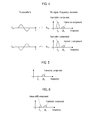
- FIG. 3 is a flow chart showing a process of providing the motion image.
- the processing unit 130 is configured to perform a data processing between ultrasound data corresponding to the n th frame and ultrasound data corresponding to the (n+1) th frame to form data ("motion data") for obtaining a frame ("sub frame”) corresponding to the motion of the target object, at step S302 in FIG. 3 . That is, the processing unit 130 is configured to perform the data processing between ultrasound data having different phases.
- the processing unit 130 is configured to add the ultrasound data corresponding to the receive signals R XA and the ultrasound data corresponding to the receive signals Rx B to thereby form data, which has the harmonic components only, while eliminating the fundamental components, as shown in FIG. 5 .
- the processing unit 130 When the target object within the living body moves, the processing unit 130 is configured to add the ultrasound data having different phases to thereby form data, which has the harmonic component and phase shift component corresponding to the motion of the target object.
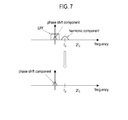
- the processing unit 130 is configured to perform downmixing upon the data, which has the harmonic component and the phase shift component, as shown in FIG 6 .
- the processing unit 130 further performs low pass filtering upon the downmixed data to thereby form the motion data, which has the phase shift component only, as shown in FIG. 7 .
- the reference numeral LPF represents a low pass filter.
- the processing unit 130 is configured to perform the data processing (adding, downmixing and filtering) between first ultrasound data corresponding to the frame BF 1 and second ultrasound data corresponding to the frame BF 2 to thereby form the motion data corresponding to the sub frame DF 1 , as shown in FIG. 8 .
- reference numerals S 1 to S n represent scanlines.
- the processing unit 130 further performs the data processing (adding, downmixing and filtering) between second ultrasound data corresponding to the frame BF 2 and first ultrasound data corresponding to the frame BF 3 to thereby form the motion data corresponding to the sub frame DF 2 .
- the processing unit 130 further forms the motion data corresponding to each of the sub frames mentioned above.
- the processing unit 130 is configured to convert the motion data into base band data, at step S304 in FIG. 3 .
- the processing unit 130 is configured to form in-phase/quadrature data ("IQ data") based on the base band data, at step S306 in FIG. 3 .
- IQ data in-phase/quadrature data
- the processing unit 130 is configured to form motion information based on the IQ data, at step S308 in FIG. 3 .
- the motion information includes velocity and power. However, it should be noted herein that the motion information may not be limited thereto.
- the processing unit 130 calculates the velocity and power by using the IQ data corresponding to an ensemble number as ensemble data.
- the methods of calculating the velocity and the power based on the IQ data are well known in the art. Thus, they have not been described in detail so as not to unnecessarily obscure the present invention.
- the processing unit 130 further forms the motion information based on the velocity and power.
- the processing unit 130 further extracts motion data corresponding to the sub frames DF 2 to DF 7 based on the ensemble number, and then form the motion information corresponding to the motion image PF 2 based on the extracted motion data.
- the processing unit 130 forms the motion information corresponding to each of the motion images mentioned above.
- the processing unit 130 is configured to form the motion image based on the motion information, at step S310 in FIG. 3 .
- the processing unit 130 is configured to form the motion image based on a gray map corresponding to the motion information. That is, the processing unit 130 forms the motion image based on the gray map, which sets a gray level (0 to 255) corresponding to the motion information (velocity and power) on each of the pixels of the motion image.
- the processing unit 130 is configured to form the motion image based on a color map corresponding to the motion information. That is, the color is provided to set a color corresponding to the motion information (velocity and power) on each of the pixels of the motion image.
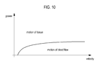
- the processing unit 130 further performs a segmentation of motion of the target object (e.g., blood flow) and motion of tissues (e.g., blood vessels, a heart, etc.).
- a segmentation of motion of the target object e.g., blood flow
- tissues e.g., blood vessels, a heart, etc.
- the methods of performing the segmentation are well known in the art. Thus, they have not been described in detail so as not to unnecessarily obscure the present invention.
- the processing unit 130 further forms the motion image based on the segmented motion.
- the processing unit 130 is configured to form a brightness mode image, at step S312 in FIG. 3 .
- the processing unit 130 retrieves the storage unit 120 to extract ultrasound data corresponding to a frame from the storage unit 120.
- the processing unit 130 further forms the brightness mode image based on the extracted ultrasound data.
- the processing unit 130 forms the brightness mode image based on the extracted ultrasound data
- the processing unit 130 extracts ultrasound data corresponding to each of the frames from the storage unit 120 and form the brightness mode images based on the extracted ultrasound data.
- the processing unit 130 is configured to perform an image compounding upon the motion image and the brightness mode image to form a compound image, at step S314 in FIG. 3 .
- the methods of performing the image compounding are well known in the art. Thus, they have not been described in detail so as not to unnecessarily obscure the present invention.
- the ultrasound system 100 further includes a display unit 140.
- the display unit 140 displays the motion image formed by the processing unit 130.
- the display unit 140 further displays the compound image.
- the display unit 140 further displays the brightness mode image.
Landscapes
- Engineering & Computer Science (AREA)
- Physics & Mathematics (AREA)
- Radar, Positioning & Navigation (AREA)
- Remote Sensing (AREA)
- Acoustics & Sound (AREA)
- Computer Networks & Wireless Communication (AREA)
- General Physics & Mathematics (AREA)
- Health & Medical Sciences (AREA)
- Life Sciences & Earth Sciences (AREA)
- Biophysics (AREA)
- Physiology (AREA)
- Ultra Sonic Daignosis Equipment (AREA)
Applications Claiming Priority (1)
| Application Number | Priority Date | Filing Date | Title |
|---|---|---|---|
| KR1020100051514A KR101120794B1 (ko) | 2010-06-01 | 2010-06-01 | 움직임 영상을 제공하는 초음파 시스템 |
Publications (2)
| Publication Number | Publication Date |
|---|---|
| EP2392945A2 true EP2392945A2 (de) | 2011-12-07 |
| EP2392945A3 EP2392945A3 (de) | 2013-08-21 |
Family
ID=44118025
Family Applications (1)
| Application Number | Title | Priority Date | Filing Date |
|---|---|---|---|
| EP11168038.5A Withdrawn EP2392945A3 (de) | 2010-06-01 | 2011-05-30 | Bereitstellung eines bewegten Bildes in einem Ultraschallsystem |
Country Status (3)
| Country | Link |
|---|---|
| US (1) | US8705802B2 (de) |
| EP (1) | EP2392945A3 (de) |
| KR (1) | KR101120794B1 (de) |
Cited By (1)
| Publication number | Priority date | Publication date | Assignee | Title |
|---|---|---|---|---|
| EP2610641A3 (de) * | 2011-12-27 | 2014-08-20 | Samsung Medison Co., Ltd. | Ultraschall und System zum Erzeugen von Doppler Ultraschallbildern |
Families Citing this family (7)
| Publication number | Priority date | Publication date | Assignee | Title |
|---|---|---|---|---|
| KR101313221B1 (ko) | 2010-11-29 | 2013-10-14 | 삼성메디슨 주식회사 | 적응적 프레임 평균 처리를 수행하는 초음파 시스템 및 방법 |
| WO2015034156A1 (en) * | 2013-09-03 | 2015-03-12 | Samsung Electronics Co., Ltd. | Methods and apparatuses for controlling ultrasound wave |
| EP3167810B1 (de) * | 2015-11-10 | 2019-02-27 | Samsung Medison Co., Ltd. | Ultraschallbildgebungsvorrichtung und verfahren zum betrieb davon |
| KR102641998B1 (ko) * | 2015-11-10 | 2024-02-28 | 삼성메디슨 주식회사 | 초음파 영상 장치 및 동작 방법 |
| US10937133B2 (en) * | 2016-11-16 | 2021-03-02 | Koninklijke Philips N.V. | Adaptive ringdown subtraction for coronary and peripheral intravascular ultrasound (IVUS) |
| EP3769692B1 (de) * | 2018-03-20 | 2024-03-27 | FUJIFILM Corporation | Ultraschalldiagnosevorrichtung und verfahren zur steuerung der ultraschalldiagnosevorrichtung |
| KR102158177B1 (ko) * | 2018-11-15 | 2020-09-22 | 서강대학교산학협력단 | 2D 샘플볼륨 기반의 스펙트럴 도플러 영상에서 Neural Network를 이용하여 움직임을 추적하는 기법 및 이를 이용한 초음파 의료 영상 장치 |
Citations (1)
| Publication number | Priority date | Publication date | Assignee | Title |
|---|---|---|---|---|
| KR20100051514A (ko) | 2008-11-07 | 2010-05-17 | 오휘진 | 가변식 표지구 |
Family Cites Families (7)
| Publication number | Priority date | Publication date | Assignee | Title |
|---|---|---|---|---|
| JP2002143158A (ja) * | 2000-10-30 | 2002-05-21 | Ge Medical Systems Global Technology Co Llc | 超音波画像表示方法および超音波診断装置 |
| JP2003010178A (ja) * | 2001-07-03 | 2003-01-14 | Toshiba Corp | 超音波診断装置 |
| JP3984810B2 (ja) * | 2001-09-21 | 2007-10-03 | ジーイー・メディカル・システムズ・グローバル・テクノロジー・カンパニー・エルエルシー | 超音波診断装置 |
| US6638228B1 (en) * | 2002-04-26 | 2003-10-28 | Koninklijke Philips Electronics N.V. | Contrast-agent enhanced color-flow imaging |
| US7037265B2 (en) * | 2003-09-09 | 2006-05-02 | Ge Medical Systems Global Technology Company, Llc | Method and apparatus for tissue harmonic imaging with natural (tissue) decoded coded excitation |
| KR101117035B1 (ko) | 2009-03-24 | 2012-03-15 | 삼성메디슨 주식회사 | 볼륨 데이터에 표면 렌더링을 수행하는 초음파 시스템 및 방법 |
| US10321892B2 (en) * | 2010-09-27 | 2019-06-18 | Siemens Medical Solutions Usa, Inc. | Computerized characterization of cardiac motion in medical diagnostic ultrasound |
-
2010
- 2010-06-01 KR KR1020100051514A patent/KR101120794B1/ko not_active Expired - Fee Related
-
2011
- 2011-05-30 EP EP11168038.5A patent/EP2392945A3/de not_active Withdrawn
- 2011-06-01 US US13/150,664 patent/US8705802B2/en active Active
Patent Citations (1)
| Publication number | Priority date | Publication date | Assignee | Title |
|---|---|---|---|---|
| KR20100051514A (ko) | 2008-11-07 | 2010-05-17 | 오휘진 | 가변식 표지구 |
Cited By (2)
| Publication number | Priority date | Publication date | Assignee | Title |
|---|---|---|---|---|
| EP2610641A3 (de) * | 2011-12-27 | 2014-08-20 | Samsung Medison Co., Ltd. | Ultraschall und System zum Erzeugen von Doppler Ultraschallbildern |
| US9474510B2 (en) | 2011-12-27 | 2016-10-25 | Samsung Medison Co., Ltd. | Ultrasound and system for forming an ultrasound image |
Also Published As
| Publication number | Publication date |
|---|---|
| US20110295116A1 (en) | 2011-12-01 |
| US8705802B2 (en) | 2014-04-22 |
| KR20110131857A (ko) | 2011-12-07 |
| EP2392945A3 (de) | 2013-08-21 |
| KR101120794B1 (ko) | 2012-03-22 |
Similar Documents
| Publication | Publication Date | Title |
|---|---|---|
| US12004898B2 (en) | Ultrasound gray-scale imaging system and method | |
| US8684934B2 (en) | Adaptively performing clutter filtering in an ultrasound system | |
| EP2392945A2 (de) | Bereitstellung eines bewegten Bildes in einem Ultraschallsystem | |
| US9907531B2 (en) | Methods and systems for ultrasonic imaging | |
| US9261485B2 (en) | Providing color doppler image based on qualification curve information in ultrasound system | |
| US20100004540A1 (en) | Dual path processing for optimal speckle tracking | |
| EP2609868A1 (de) | Bereitstellung einer Benutzerschnittstelle in einem Ultraschallsystem | |
| US20110137168A1 (en) | Providing a three-dimensional ultrasound image based on a sub region of interest in an ultrasound system | |
| EP2180339A1 (de) | Dopplersignalverarbeitung für ein erweitertes Spektraldopplerbild | |
| EP2610641B1 (de) | Ultraschall und System zum Erzeugen von Doppler Ultraschallbildern | |
| US9078590B2 (en) | Providing additional information corresponding to change of blood flow with a time in ultrasound system | |
| JP2014036848A (ja) | 超音波イメージング・システム及び方法 | |
| EP2609866B1 (de) | Bereitstellung von Bewegungsmodusbildern in einem Ultraschallsystem | |
| US8545411B2 (en) | Ultrasound system and method for adaptively performing clutter filtering | |
| EP2425784A1 (de) | Bereitstellung eines Farbdopplermodusbilds in einem Ultraschallsystem | |
| EP2610638A2 (de) | Erzeugung von Vektorinformationen basierend auf dem Vektordoppler in einem Ultraschallsystem | |
| EP2345911A1 (de) | Bereitstellung von mindestens einer Schnittabbildung auf mindestens drei Punkten in einem Ultraschallsystem | |
| US11690597B2 (en) | Ultrasonic diagnostic apparatus | |
| CN112842382B (zh) | 用于对信道数据进行流处理以应用非线性波束形成的方法和系统 | |
| EP2422704A2 (de) | Bereitstellung von Ultraschallraumverbindungsbildern in einem Ultraschallsystem | |
| JP2009261436A (ja) | 超音波診断装置 | |
| Hyun et al. | A GPU-based real-time spatial coherence imaging system | |
| JP4537754B2 (ja) | 超音波診断装置及びパルスドプラ計測装置 | |
| JP2005006718A (ja) | 超音波診断装置 |
Legal Events
| Date | Code | Title | Description |
|---|---|---|---|
| AK | Designated contracting states |
Kind code of ref document: A2 Designated state(s): AL AT BE BG CH CY CZ DE DK EE ES FI FR GB GR HR HU IE IS IT LI LT LU LV MC MK MT NL NO PL PT RO RS SE SI SK SM TR |
|
| AX | Request for extension of the european patent |
Extension state: BA ME |
|
| PUAI | Public reference made under article 153(3) epc to a published international application that has entered the european phase |
Free format text: ORIGINAL CODE: 0009012 |
|
| PUAL | Search report despatched |
Free format text: ORIGINAL CODE: 0009013 |
|
| AK | Designated contracting states |
Kind code of ref document: A3 Designated state(s): AL AT BE BG CH CY CZ DE DK EE ES FI FR GB GR HR HU IE IS IT LI LT LU LV MC MK MT NL NO PL PT RO RS SE SI SK SM TR |
|
| AX | Request for extension of the european patent |
Extension state: BA ME |
|
| RIC1 | Information provided on ipc code assigned before grant |
Ipc: G01S 15/89 20060101AFI20130715BHEP |
|
| STAA | Information on the status of an ep patent application or granted ep patent |
Free format text: STATUS: THE APPLICATION IS DEEMED TO BE WITHDRAWN |
|
| 18D | Application deemed to be withdrawn |
Effective date: 20140222 |