EP2247936B1 - Vorrichtung zum testen der beschichtung eines schaufelsockels - Google Patents
Vorrichtung zum testen der beschichtung eines schaufelsockels Download PDFInfo
- Publication number
- EP2247936B1 EP2247936B1 EP09720983A EP09720983A EP2247936B1 EP 2247936 B1 EP2247936 B1 EP 2247936B1 EP 09720983 A EP09720983 A EP 09720983A EP 09720983 A EP09720983 A EP 09720983A EP 2247936 B1 EP2247936 B1 EP 2247936B1
- Authority
- EP
- European Patent Office
- Prior art keywords
- test piece
- test
- counter
- tensile
- halves
- Prior art date
- Legal status (The legal status is an assumption and is not a legal conclusion. Google has not performed a legal analysis and makes no representation as to the accuracy of the status listed.)
- Active
Links
Images

Classifications
-
- G—PHYSICS
- G01—MEASURING; TESTING
- G01N—INVESTIGATING OR ANALYSING MATERIALS BY DETERMINING THEIR CHEMICAL OR PHYSICAL PROPERTIES
- G01N3/00—Investigating strength properties of solid materials by application of mechanical stress
- G01N3/56—Investigating resistance to wear or abrasion
Definitions
- the invention relates to the field of anti-friction coatings applied on blade roots of rotating machines, and the quality control thereof. More specifically, the invention relates to a device for testing a coating capable of coating a turbine engine rotor blade root. It may be a land or aerospace turbomachine, and in particular a jet engine or an airplane turboprop.
- the blades, and in particular the fan blades in the aerospace turbomachines are extremely stressed mechanical parts. For this reason, the blade root which is the part of holding the dawn is a particularly critical part of the piece.
- the blade root has contact surfaces with the rotor disk, or bearings, which are subjected to high pressure and temperature operation.
- anti-friction coatings are used in known manner. These so-called antifretting coatings can be deposited in particular by thermal spraying. They can be multi-layered.
- the aim of the invention is to define a device for testing a coating capable of coating a turbine engine rotor blade root, enabling a more discriminating test to be performed than the previous tests as to the quality of the coatings tested. , and the results of which are strongly correlated with the real observations of the durability of blade root coatings, as seen throughout the life of a blade, are commonly from 10,000 to 15,000 cycles.
- the device comprises two half-test pieces, each having a bearing surface coated with said coating, a counter-test piece having two bearing surfaces, and a machine comprising a first holding system for holding the test-tube along an axis.
- a second holding system for holding the half-specimens around the counter-specimen, and traction means for subjecting the holding systems to predetermined traction cycles along the axis of traction, during which the force traction is transmitted from one holding system to the other via the respective bearing surfaces in contact with the test-tube and half-test pieces; and that the second holding system comprises elastic return means permitting the spacing of the two half-specimens in a direction perpendicular to the direction of traction in response to a spreading force exerted on these two half-specimens by the counter-force. test piece during a traction cycle.
- the principle of the test thus defined is fundamentally different from the previously known tests. Indeed, it consists in subjecting coated test pieces to fatigue tests representative of the stresses to which the blade roots are exposed during the life of the dawn.
- the device does not require the use of actual vanes but simply the use of half-specimens, each having a scope covered with the coating to be tested. Note that it is perfectly possible furthermore that each half-test piece has not only one but several scopes, the counter-test then having a bearing corresponding to each of these scopes of the two half-test pieces.
- the first and second holding systems respectively hold the half-test pieces and the counter-test-piece facing each other, so as to make their litters coincide.
- the holding systems are then subjected to tensile movements relative to one another by known means, so as to subject the bearing surfaces and in particular the bearing surfaces of the half-samples to solicitations representative of those experienced by a dawn foot in operation.
- the load ramp rate parameter i.e. the increase of the tensile force per unit of time, can also be used as a variable that can be optimized.
- the attachment of a blade on a rotor disk is generally made by a mortise / tenon coupling forming a fastener.
- This attachment consists of a tenon arranged on a radially inner end of the blade, the blade root, which is fixed in a mortise provided on the periphery of the rotor disc.
- the blades are regularly attached to the outer periphery of the rotor disk, which thus has as many attachment cells and dovetail tenons as there are blades to be fixed.
- the blades of the blades on the rotor disk thus form a pattern which repeats in the circumferential direction and which comprises the dovetail pin of the rotor disk with the two half-feet of blades which enclose it in the wheel to blades. It is this motive that reproduces the counter-specimen enclosed by the two half-specimens.
- the second holding system comprises elastic return means permitting the spacing of the two half-specimens in a direction perpendicular to the direction of traction in response to a force of the spacing exerted on these two half-test pieces by the counter-test piece during a traction cycle.
- the counter-test piece presses the half-test pieces, and can tend to move the half-test pieces in a transverse direction, perpendicular to the direction of traction.
- the second holding system comprises the aforementioned elastic return means, which allow to maintain relative positions of the test-tube and half-test pieces which are representative of the actual positions of the blade root and a rotor disk stud in a turbomachine.
- the scopes of the half-specimens are oblique with respect to the axis of traction, so as to be representative of the shape of the staves of a turbine engine rotor blade root.
- the angle formed by the range of the half-test pieces is representative of that formed by a blade root surface in a turbomachine with respect to the radial direction of the latter.
- the angle of the raised relative to the direction of traction may be close to 45 °; more generally, this angle can vary between 30 and 60 °.
- half-test pieces may be representative of a blade root not only by the shape of their bearings, but also by their material.
- usually half-test pieces are made in the same material as the blade root, typically in a titanium-based or nickel-based alloy.
- the surfaces of the counter-test piece are oblique with respect to the axis of traction so as to be representative of the shape of the bearing surfaces of a stud of a turbomachine rotor disk.
- the angle formed by the range of the counter-test specimen is representative of that formed by a rotor disk stud surface in a turbomachine with respect to the radial direction thereof.
- the fact that the range of the counter-test piece applies to the half-test piece is representative of that which the range of a rotor disk stud applies to the blade root reach in a turbomachine.
- the surfaces of the counter-test piece are inclined at an angle of between 30 and 60 °, and an angle close to 45 ° is generally retained.
- the elastic return means comprise at least one bar made of an elastic material, deforming while remaining in its elastic deformation range during the traction cycles.
- the bar thus has a certain capacity of deformation, which allows the machine to represent, to simulate the deformations actually found in operation in the turbomachine, that is the deformations of the blade root and / or the tenon of the rotor disk. With this possibility of separation of the two half-test pieces, the representativity of the results obtained by the test device is further increased.
- the second holding system comprises two posts parallel to the axis of traction and serving to maintain the two half-test pieces, said bar connecting these amounts in a direction perpendicular to the axis of traction.
- the two uprights parallel to the axis of traction, in the vicinity of the half-test pieces, make it possible to guarantee that these are held in position during the pulling cycles. It is therefore preferable that the half-test pieces are relatively elongated, to facilitate their locking in rotation.
- the spacing forces in a direction transverse to the direction of traction pass through said at least one bar, it can be dimensioned easily as a function of the extension forces that it is required to undergo and the elongation considered permissible under the effect of these efforts.
- the test device further comprises means for measuring the spacing of the half-test pieces during the test. It is thus possible at any time to ensure that the relative positions of the test-tube and half-test pieces correspond to what has been envisaged.
- the half-test pieces have, in the vicinity of their seats, a representative form of half-feet of turbomachine rotor blades, and the traction axis is arranged substantially in the radial direction of the half-feet of the turbine. blades.
- This arrangement allows half test pieces to be tested under conditions that faithfully reproduce actual operating and stress conditions.
- the simulation of the behavior of the blade foot coating is not limited to the actual area of the coating, but integrates the blade root portion located in the vicinity of the or litters.
- the counter-test piece has in the vicinity of its seats a form representative of the shape of a stud of a turbomachine rotor disc.
- the action of the counter-test specimen which reproduces that of the rotor disc stud on the blade root, is more realistic, since it is able to reproduce the behavior of the rotor disc stud, not only in the immediate vicinity of the one or more staves, but over the entire portion of the tenon located in the vicinity of the staves, that is to say usually the entire end of the stud-shaped test-tube.
- the half-test pieces facing each other are comparable to the opposite faces of a blade root, the counter-test-tube being for its part comparable to the pin of the rotor disc used to fix the blade on the rotor.
- the blade root which is clamped and fixed between two tenons of the rotor disk
- the two half-test tubes which enclose the part and another counter-specimen representing a tenon of the rotor disc. It has been found that despite this seemingly reversed disposition, excellent representativeness of the results is obtained.
- the half-specimen side located on the side of the test-tube is without undercut. These are therefore economical because they can be machined simply in 3-axis machining. The same goes for the counter-specimen.
- the half-test pieces may even be of external convex shape on the side of the test-tube.
- the movements of the specimens in the direction of traction can be measured and recorded by a displacement measuring system such as a comparator or a gauge.
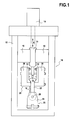
- This device 10 comprises a machine comprising firstly a carrier structure 12 generally constituted by a welded frame.
- This supporting structure 12 supports two holding systems 20 and 30.
- the first holding system 20 located in the lower part of the machine comprises a fixed column 29 which holds in position the counter-test tube 22.
- the counter-test piece 22 comprises a bore in which passes an axis 26 of the first holding system, axis through which the counter-test piece 22 is maintained regardless of the tensile stresses it receives.
- the second holding system 30 serves to maintain in position two half-test pieces 32.
- This second holding system 30 comprises a movable beam 39 set in reciprocating rectilinear translation movement in the vertical direction along the double arrow A by a linear actuator 14 or any other means of equivalent actuation.
- This beam 39 is guided in its reciprocating translation movement by the slides 16.
- the holding system 30 further comprises means for rigidly connecting the half-specimens 32 relative to the beam 39, which include the uprights 38 mentioned above.
- the characteristics of the linear actuator 14 are chosen so that it can print to the second holding system 30 relative to the first 20 translational movements which are representative of those made by a blade and more precisely the foot of the blade relative to the rotor disk during operation of the turbomachine to which the blade belongs. These movements are due to the considerable centrifugal forces received by the blades during the rotation of the engine, similar to a radial traction on the blade.
- the support structure 12 and the linear actuator 14 of the machine according to the invention it is possible to use standard components conventionally used in cyclic tensile testing machines. mechanical parts.
- the cycles to be reproduced generally have the following characteristics: Cycle number of up to 10,000 or 15,000 cycles; maximum applied force varying between 15,000 and 30,000 daN.
- the counter-test piece 22 comprises a hole 24 and the first holding system comprises an axis 26 through which the counter-test piece 22 is held regardless of the tensile stresses it receives.
- FIG. 2A is a sectional view showing the two half-test pieces 32, maintained on the one hand in the second holding system 30 (uprights 38), and on the other hand by the test-tube 22.
- the role of the second holding system 30 is to maintain the two half-test pieces and more precisely the bearing surfaces 24 thereof in front of the corresponding spans (ref.25, Fig.3 ) of the counter-test piece 22, and to transmit to the half-test pieces 32 an alternating translational movement with respect to the counter-test piece 22.
- the counter-test piece 22 at one of its ends (that of the top on the figure 1 ), has a relatively symmetrical bulb whose sides 23 project cantilevered on either side of its axis. Low external surfaces (in the sense of the figure 1 ) of these sides 23 are the contact surfaces or worn of the counter-test piece 22. These spans reproduce the shape of the rotor disc pin of the turbomachine on which the blade root is mounted.
- the counter-test piece 22 has fastening means, enabling it to be fixed on the test machine by means of first holding means for holding and securing the test-tube during the test-tests. traction.
- These holding means here comprise a bore 24, provided to pass a fixing axis of the test machine.
- the staves 24 of the half-test pieces 32 are located on the inclined upper faces of bulges 35 formed on the basis of the half-test pieces 32. These staves are contact surfaces. comparable to the litters of a dawn foot.
- the second holding system is biased in upward traction (in the sense of the figure 1 )
- the respective bearing surfaces 24 of the half-test pieces and 25 of the test-tube come into contact and thereby oppose the upward movement of the second holding system 30, which makes it possible to test, to put to the test the coating 34 deposited on the bearing surfaces 24 of the half-test pieces.
- the second holding system 30 comprises two uprights 38 parallel to the axis of traction and serving to hold the two half-test pieces, each being fixed to a half-test piece 32.
- This attachment can be made in particular by means of bolts 42.
- bolts 42 pass through on the one hand the amount 38 and are further fixed through the half-test piece 32 in a bore, an oblong or a oblong opening 41 as shown on the Figure 2B .
- the two uprights 38 can be fixed rigidly to one another or even to form a single piece, they advantageously can constitute independent parts of the second holding system 30.
- the two uprights 38 can deviate laterally relative to each other. This spacing is in the direction perpendicular to the direction of traction and perpendicular to the different scopes of the blade root. This degree of freedom makes it possible to better reproduce the conditions for maintaining the blade during operation.
- the spacing of the two parts of the holding system is limited by elastic return means.
- These elastic return means are constituted by four metal bars 40, which deform during the tensile cycles while remaining in their elastic deformation field. These bars 40 connect the uprights 38 in a direction perpendicular to the axis of traction. They are threaded at their free ends, so as to be fixed by bolting.
- the machine further comprises means 18 for measuring the spacing of the half-test pieces during the test. This measurement ensures the proper functioning and positioning of the various parts during the test.
- the half-test piece 32 is shown resting on the upright 38.
- the half-test piece 32 comprises a bearing surface 24 which extends between a point B and a point D.
- the test-tube also comprises a bearing surface 25, which faces the span 24 of the half-test piece 32.
- the span 24 of the half-test piece is coated with a coating of the same type and applied in the same method as the corresponding zone of the blade root.
- the position of this contact zone varies with respect to the range.
- the ranges of the test piece 22 and half-test piece 32 are arranged in a direction oblique or inclined with respect to the direction E, which is the direction of traction.
- This inclination is the one found in the attachment of the blade root on the rotor disc.
- the angle of inclination ⁇ is close to 45 °.
Landscapes
- Physics & Mathematics (AREA)
- Health & Medical Sciences (AREA)
- Life Sciences & Earth Sciences (AREA)
- Chemical & Material Sciences (AREA)
- Analytical Chemistry (AREA)
- Biochemistry (AREA)
- General Health & Medical Sciences (AREA)
- General Physics & Mathematics (AREA)
- Immunology (AREA)
- Pathology (AREA)
- Turbine Rotor Nozzle Sealing (AREA)
- Investigating Strength Of Materials By Application Of Mechanical Stress (AREA)
- Structures Of Non-Positive Displacement Pumps (AREA)
- Coating Apparatus (AREA)
- Application Of Or Painting With Fluid Materials (AREA)
- Medicinal Preparation (AREA)
- Testing Of Devices, Machine Parts, Or Other Structures Thereof (AREA)
Claims (11)
- Vorrichtung (10) zum Prüfen einer Beschichtung (36), die geeignet ist, einen Schaufelfuß eines Rotors einer Turbomaschine zu umhüllen, wobei die Vorrichtung zwei halbe Prüfkörper (32), wobei ein jeder eine mit der Beschichtung überzogene Auflagefläche (24) aufweist, einen Gegenprüfkörper (22), der zwei Auflageflächen (25) aufweist, sowie eine Prüfmaschine umfaßt, die ein erstes Haltesystem (20) zum Halten des Gegenprüfkörpers (22) entlang einer Zugachse (A), ein zweites Haltesystem (30) zum Halten der halben Prüfkörper (32) um den Gegenprüfkörper (22) herum, Zugmittel (14), um die Haltesysteme vorbestimmten Zugzyklen entlang der Zugachse zu unterziehen, während derer die Zugkraft über die jeweiligen in Kontakt befindlichen Auflageflächen (25, 24) des Gegenprüfkörpers und der halben Prüfkörper von einem Haltesystem auf das andere übertragen wird, umfaßt, wobei die Vorrichtung dadurch gekennzeichnet ist, daß das zweite Haltesystem elastische Rückstellmittel (40) umfaßt, die das Spreizen der beiden halben Prüfkörper in einer Richtung senkrecht zur Zugrichtung als Reaktion auf eine Spreizkraft, die während eines Zugzyklus durch den Gegenprüfkörper auf diese beiden halben Prüfkörper ausgeübt wird, zulassen.
- Prüfvorrichtung nach Anspruch 1, dadurch gekennzeichnet, daß die Seite der halben Prüfkörper (32), die auf der Seite des Gegenprüfkörpers (22) liegt, keine Hinterschneidung aufweist.
- Prüfvorrichtung nach Anspruch 1 oder 2, dadurch gekennzeichnet, daß die Auflageflächen (24) der halben Prüfkörper gegenüber der Zugachse schräg verlaufen, so daß sie für die Form der Auflageflächen eines Schaufelfußes eines Rotors einer Turbomaschine repräsentativ sind.
- Prüfvorrichtung nach einem der Ansprüche 1 bis 3, dadurch gekennzeichnet, daß die Auflageflächen (25) des Gegenprüfkörpers (22) gegenüber der Zugsachse schräg verlaufen, so daß sie für die Form der Auflageflächen eines Zapfens einer Rotorscheibe einer Turbomaschine repräsentativ sind.
- Prüfvorrichtung nach einem der Ansprüche 1 bis 4, dadurch gekennzeichnet, daß die elastischen Rückstellmittel wenigstens einen aus einem elastischen Material bestehenden Stab (40) umfassen, der sich während der Zugzyklen verformt und dabei in seinem Bereich elastischer Verformung bleibt.
- Prüfvorrichtung nach einem der Ansprüche 1 bis 5, dadurch gekennzeichnet, daß das zweite Haltesystem (30) zwei Holme (38) umfaßt, die zur Zugachse parallel verlaufen und dazu dienen, die beiden halben Prüfkörper (32) zu halten, wobei der Stab diese Holme entlang einer zur Zugachse senkrechten Richtung verbindet.
- Prüfvorrichtung nach einem der Ansprüche 1 bis 6, dadurch gekennzeichnet, daß sie ferner Mittel (18) zum Messen des Abstandes der halben Prüfkörper während der Prüfung umfaßt.
- Prüfvorrichtung nach einem der Ansprüche 1 bis 7, dadurch gekennzeichnet, daß die halben Prüfkörper (32) in der Nähe ihrer Auflageflächen eine halbe Schaufelfüße eines Rotors einer Turbomaschine darstellende Form aufweisen und die Zugachse im wesentlichen entlang der radialen Richtung der halben Schaufelfüße angeordnet ist.
- Prüfvorrichtung nach einem der Ansprüche 1 bis 8, dadurch gekennzeichnet, daß der Gegenprüfkörper (22) in der Nähe seiner Auflageflächen eine die Form eines Zapfens einer Rotorscheibe einer Turbomaschine darstellende Form aufweist.
- Prüfvorrichtung nach einem der Ansprüche 1 bis 9, dadurch gekennzeichnet, daß der Gegenprüfkörper aus einer Legierung auf Titan- oder Nickelbasis gebildet ist.
- Prüfvorrichtung nach einem der Ansprüche 1 bis 10, dadurch gekennzeichnet, daß die halben Prüfkörper aus einer Legierung auf Titan- oder Nickelbasis gebildet sind.
Applications Claiming Priority (2)
| Application Number | Priority Date | Filing Date | Title |
|---|---|---|---|
| FR0851183A FR2927998A1 (fr) | 2008-02-25 | 2008-02-25 | Machine de test d'un revetement pour pied d'aube. |
| PCT/FR2009/050296 WO2009112757A1 (fr) | 2008-02-25 | 2009-02-25 | Dispositif de test d'un revetement pour pied d'aube |
Publications (2)
| Publication Number | Publication Date |
|---|---|
| EP2247936A1 EP2247936A1 (de) | 2010-11-10 |
| EP2247936B1 true EP2247936B1 (de) | 2011-08-31 |
Family
ID=39900868
Family Applications (1)
| Application Number | Title | Priority Date | Filing Date |
|---|---|---|---|
| EP09720983A Active EP2247936B1 (de) | 2008-02-25 | 2009-02-25 | Vorrichtung zum testen der beschichtung eines schaufelsockels |
Country Status (11)
| Country | Link |
|---|---|
| US (1) | US8408068B2 (de) |
| EP (1) | EP2247936B1 (de) |
| JP (1) | JP5265707B2 (de) |
| CN (1) | CN101960284B (de) |
| AT (1) | ATE522799T1 (de) |
| BR (1) | BRPI0907536B1 (de) |
| CA (1) | CA2716242C (de) |
| ES (1) | ES2372265T3 (de) |
| FR (1) | FR2927998A1 (de) |
| RU (1) | RU2489702C2 (de) |
| WO (1) | WO2009112757A1 (de) |
Families Citing this family (8)
| Publication number | Priority date | Publication date | Assignee | Title |
|---|---|---|---|---|
| GB2472193A (en) * | 2009-07-27 | 2011-02-02 | Rolls Royce Plc | Rotor blade test specimen |
| CN102207437B (zh) * | 2011-03-04 | 2013-04-03 | 立邦涂料(中国)有限公司 | 一种弹性涂料的测试装置及其测试方法 |
| FR3005733B1 (fr) * | 2013-05-17 | 2015-04-24 | Snecma | Banc d'essai en fatigue oligocyclique ou en fatigue oligocyclique et polycyclique |
| FR3005734B1 (fr) * | 2013-05-17 | 2016-01-29 | Snecma | Optimisation d'un banc d'essai en fatigue oligocyclique ou en fatigue oligocyclique et polycyclique |
| CN104568619B (zh) * | 2014-12-24 | 2017-04-05 | 西南交通大学 | 一种微动疲劳试验系统的法向加载装置 |
| CN107024386B (zh) * | 2017-04-27 | 2019-04-23 | 北京航空航天大学 | 用于叶片载荷施加的试验装置 |
| KR102366031B1 (ko) * | 2017-06-15 | 2022-02-22 | 삼성디스플레이 주식회사 | 전단 응력 시험 장치 |
| WO2020208925A1 (ja) * | 2019-04-12 | 2020-10-15 | 株式会社Ihi | 動翼の振動試験用治具 |
Family Cites Families (26)
| Publication number | Priority date | Publication date | Assignee | Title |
|---|---|---|---|---|
| US3802255A (en) * | 1972-03-08 | 1974-04-09 | Us Air Force | Fixture for tensile and stress rupture testing of turbine blades |
| US4541287A (en) * | 1983-03-28 | 1985-09-17 | The United States Of America As Represented By The United States Department Of Energy | Method of measuring metal coating adhesion |
| JPS6257146U (de) * | 1985-09-28 | 1987-04-09 | ||
| JPH03251735A (ja) * | 1990-02-28 | 1991-11-11 | Shimadzu Corp | 試験片用つかみ具 |
| JP2506684Y2 (ja) * | 1990-04-27 | 1996-08-14 | 株式会社島津製作所 | 材料試験機 |
| JP2522822Y2 (ja) * | 1990-05-22 | 1997-01-16 | 株式会社島津製作所 | 材料試験機 |
| US5160243A (en) * | 1991-01-15 | 1992-11-03 | General Electric Company | Turbine blade wear protection system with multilayer shim |
| US5240375A (en) * | 1992-01-10 | 1993-08-31 | General Electric Company | Wear protection system for turbine engine rotor and blade |
| JP2586080Y2 (ja) * | 1992-03-31 | 1998-12-02 | 株式会社島津製作所 | 材料試験機 |
| RU2089878C1 (ru) * | 1993-12-06 | 1997-09-10 | Шелест Сергей Орестович | Способ измерения эрозионного износа кромок рабочих лопаток турбины и устройство для его осуществления |
| ZA952222B (en) * | 1994-03-17 | 1995-12-14 | Sherritt Inc | Low friction cobalt based coatings for titanium |
| US6267558B1 (en) * | 1999-05-26 | 2001-07-31 | General Electric Company | Dual intensity peening and aluminum-bronze wear coating surface enhancement |
| US6250166B1 (en) * | 1999-06-04 | 2001-06-26 | General Electric Company | Simulated dovetail testing |
| US6290466B1 (en) * | 1999-09-17 | 2001-09-18 | General Electric Company | Composite blade root attachment |
| JP2001337016A (ja) * | 2000-05-29 | 2001-12-07 | Ishikawajima Harima Heavy Ind Co Ltd | 引張試験機のダブテール固定構造 |
| JP2002310867A (ja) * | 2001-04-16 | 2002-10-23 | Hitachi Ltd | フレッテイング疲労評価方法 |
| FR2841609B1 (fr) | 2002-06-27 | 2004-09-10 | Snecma Moteurs | Cale de retenue du pied des aubes de soufflante |
| FR2844562B1 (fr) | 2002-09-18 | 2004-10-29 | Snecma Moteurs | Maitrise de la position axiale d'une aube de rotor de soufflante |
| US7144602B2 (en) | 2003-04-25 | 2006-12-05 | Snecma Moteurs | Process for obtaining a flexible/adaptive thermal barrier |
| GB0410967D0 (en) * | 2004-05-17 | 2004-06-16 | Rolls Royce Plc | An apparatus and method for fatigue testing |
| FR2872884B1 (fr) * | 2004-07-07 | 2006-11-10 | Snecma Moteurs Sa | Procede de protection des surfaces de contact entre deux pieces metalliques beneficiant d'une telle protection |
| FR2883574B1 (fr) | 2005-03-23 | 2008-01-18 | Snecma Moteurs Sa | "procede de depot par projection thermique d'un revetement anti-usure" |
| CN100489524C (zh) * | 2005-07-21 | 2009-05-20 | 北京航空航天大学 | 热障涂层服役环境模拟装置及模拟环境控制方法 |
| JP4692462B2 (ja) * | 2006-10-12 | 2011-06-01 | 株式会社Ihi | 摺動構造体及び皮膜形成方法 |
| RU2339930C1 (ru) * | 2007-04-24 | 2008-11-27 | Федеральное государственное унитарное предприятие "Центральный институт авиационного моторостроения имени П.И. Баранова" | Способ определения прочностных свойств высокотемпературных теплозащитных покрытий деталей и устройство для его осуществления |
| FR2927997A1 (fr) * | 2008-02-25 | 2009-08-28 | Snecma Sa | Procede pour tester un revetement de pied d'aube. |
-
2008
- 2008-02-25 FR FR0851183A patent/FR2927998A1/fr not_active Withdrawn
-
2009
- 2009-02-25 ES ES09720983T patent/ES2372265T3/es active Active
- 2009-02-25 CN CN200980106374.9A patent/CN101960284B/zh active Active
- 2009-02-25 BR BRPI0907536-4A patent/BRPI0907536B1/pt not_active IP Right Cessation
- 2009-02-25 AT AT09720983T patent/ATE522799T1/de not_active IP Right Cessation
- 2009-02-25 US US12/919,017 patent/US8408068B2/en active Active
- 2009-02-25 JP JP2010547236A patent/JP5265707B2/ja active Active
- 2009-02-25 WO PCT/FR2009/050296 patent/WO2009112757A1/fr not_active Ceased
- 2009-02-25 RU RU2010139414/28A patent/RU2489702C2/ru active
- 2009-02-25 CA CA2716242A patent/CA2716242C/fr active Active
- 2009-02-25 EP EP09720983A patent/EP2247936B1/de active Active
Also Published As
| Publication number | Publication date |
|---|---|
| FR2927998A1 (fr) | 2009-08-28 |
| CA2716242C (fr) | 2016-07-12 |
| EP2247936A1 (de) | 2010-11-10 |
| JP5265707B2 (ja) | 2013-08-14 |
| WO2009112757A1 (fr) | 2009-09-17 |
| US20110000308A1 (en) | 2011-01-06 |
| BRPI0907536A2 (pt) | 2015-07-28 |
| RU2010139414A (ru) | 2012-04-10 |
| CN101960284B (zh) | 2013-06-05 |
| US8408068B2 (en) | 2013-04-02 |
| CN101960284A (zh) | 2011-01-26 |
| ES2372265T3 (es) | 2012-01-17 |
| BRPI0907536B1 (pt) | 2019-05-07 |
| JP2011513701A (ja) | 2011-04-28 |
| CA2716242A1 (fr) | 2009-09-17 |
| ATE522799T1 (de) | 2011-09-15 |
| RU2489702C2 (ru) | 2013-08-10 |
Similar Documents
| Publication | Publication Date | Title |
|---|---|---|
| EP2247936B1 (de) | Vorrichtung zum testen der beschichtung eines schaufelsockels | |
| CA2716227C (fr) | Procede pour tester un revetement de pied d'aube | |
| EP1870192B1 (de) | Vorrichtung zum Spannen von Werkstücken bei einem Reparaturverfahren einer Schaufel einer integral beschaufelten Turbinenrotorscheibe | |
| CA2732032C (fr) | Dispositif amortisseur de vibrations pour attaches d'aubes de turbomachine, turbomachine et moteurs associes | |
| EP4185778B1 (de) | Anordnung mit einer schaufel und einem system zur winkeleinstellung der schaufel | |
| CA2912163C (fr) | Banc d'essai en fatigue oligocyclique ou en fatigue oligocyclique et polycyclique | |
| CA2593193A1 (fr) | Rotor de turbomachine et turbomachine comportant un tel rotor | |
| WO2011161371A1 (fr) | Roue mobile a aubes en materiau composite pour moteur a turbine a gaz a liaison pied d'aube/disque par serrage | |
| FR2993359A1 (fr) | Procede de realisation d'un essai en fatigue vibratoire d'une piece mecanique | |
| FR3084161A1 (fr) | Montage d'essai, et machine de test en fatigue vibratoire. | |
| FR3039676A1 (fr) | Procede de determination d'une contrainte alternee maximale admissible pour une piece soumise a des sollicitations cycliques; unite de determination d'une telle contrainte | |
| FR2995004A1 (fr) | Aube de turbomachine en materiau composite et son attache sur un disque de rotor | |
| FR3140947A1 (fr) | Installation de mesure de l’amortissement procure par des ajouts de matiere sur des talons d’aubes | |
| FR2751411A1 (fr) | Systeme mecanique d'application d'efforts sur des pistes subissant en outre les sollicitations de contact | |
| FR3149386A1 (fr) | Procede d’essai d’une eprouvette de disque de frein d’aeronef et outillage associe. | |
| FR3153373A1 (fr) | Ensemble comprenant une aube et un systeme de maintien de l'aube | |
| FR3153891A1 (fr) | Éprouvette d’essai et dispositif pour la caractérisation d’un amortissement vibratoire d’un contact entre deux pièces | |
| FR3047766A1 (fr) | Element d'assemblage des disques d'un rotor de turbine, rotor et turbine associes | |
| FR2954486A1 (fr) | Procede ameliore de controle de surface d'une partie tournante d'un module de turbomachine d'aeronef, par prise d'empreinte |
Legal Events
| Date | Code | Title | Description |
|---|---|---|---|
| PUAI | Public reference made under article 153(3) epc to a published international application that has entered the european phase |
Free format text: ORIGINAL CODE: 0009012 |
|
| 17P | Request for examination filed |
Effective date: 20100823 |
|
| AK | Designated contracting states |
Kind code of ref document: A1 Designated state(s): AT BE BG CH CY CZ DE DK EE ES FI FR GB GR HR HU IE IS IT LI LT LU LV MC MK MT NL NO PL PT RO SE SI SK TR |
|
| AX | Request for extension of the european patent |
Extension state: AL BA RS |
|
| GRAP | Despatch of communication of intention to grant a patent |
Free format text: ORIGINAL CODE: EPIDOSNIGR1 |
|
| GRAC | Information related to communication of intention to grant a patent modified |
Free format text: ORIGINAL CODE: EPIDOSCIGR1 |
|
| DAX | Request for extension of the european patent (deleted) | ||
| GRAS | Grant fee paid |
Free format text: ORIGINAL CODE: EPIDOSNIGR3 |
|
| GRAA | (expected) grant |
Free format text: ORIGINAL CODE: 0009210 |
|
| AK | Designated contracting states |
Kind code of ref document: B1 Designated state(s): AT BE BG CH CY CZ DE DK EE ES FI FR GB GR HR HU IE IS IT LI LT LU LV MC MK MT NL NO PL PT RO SE SI SK TR |
|
| REG | Reference to a national code |
Ref country code: CH Ref legal event code: EP Ref country code: GB Ref legal event code: FG4D Free format text: NOT ENGLISH |
|
| REG | Reference to a national code |
Ref country code: IE Ref legal event code: FG4D Free format text: LANGUAGE OF EP DOCUMENT: FRENCH |
|
| REG | Reference to a national code |
Ref country code: DE Ref legal event code: R096 Ref document number: 602009002446 Country of ref document: DE Effective date: 20111110 |
|
| REG | Reference to a national code |
Ref country code: SE Ref legal event code: TRGR |
|
| REG | Reference to a national code |
Ref country code: NL Ref legal event code: VDEP Effective date: 20110831 |
|
| REG | Reference to a national code |
Ref country code: ES Ref legal event code: FG2A Ref document number: 2372265 Country of ref document: ES Kind code of ref document: T3 Effective date: 20120117 |
|
| LTIE | Lt: invalidation of european patent or patent extension |
Effective date: 20110831 |
|
| PG25 | Lapsed in a contracting state [announced via postgrant information from national office to epo] |
Ref country code: FI Free format text: LAPSE BECAUSE OF FAILURE TO SUBMIT A TRANSLATION OF THE DESCRIPTION OR TO PAY THE FEE WITHIN THE PRESCRIBED TIME-LIMIT Effective date: 20110831 Ref country code: NO Free format text: LAPSE BECAUSE OF FAILURE TO SUBMIT A TRANSLATION OF THE DESCRIPTION OR TO PAY THE FEE WITHIN THE PRESCRIBED TIME-LIMIT Effective date: 20111130 Ref country code: LT Free format text: LAPSE BECAUSE OF FAILURE TO SUBMIT A TRANSLATION OF THE DESCRIPTION OR TO PAY THE FEE WITHIN THE PRESCRIBED TIME-LIMIT Effective date: 20110831 Ref country code: IS Free format text: LAPSE BECAUSE OF FAILURE TO SUBMIT A TRANSLATION OF THE DESCRIPTION OR TO PAY THE FEE WITHIN THE PRESCRIBED TIME-LIMIT Effective date: 20111231 Ref country code: HR Free format text: LAPSE BECAUSE OF FAILURE TO SUBMIT A TRANSLATION OF THE DESCRIPTION OR TO PAY THE FEE WITHIN THE PRESCRIBED TIME-LIMIT Effective date: 20110831 Ref country code: NL Free format text: LAPSE BECAUSE OF FAILURE TO SUBMIT A TRANSLATION OF THE DESCRIPTION OR TO PAY THE FEE WITHIN THE PRESCRIBED TIME-LIMIT Effective date: 20110831 |
|
| REG | Reference to a national code |
Ref country code: AT Ref legal event code: MK05 Ref document number: 522799 Country of ref document: AT Kind code of ref document: T Effective date: 20110831 |
|
| PG25 | Lapsed in a contracting state [announced via postgrant information from national office to epo] |
Ref country code: CY Free format text: LAPSE BECAUSE OF FAILURE TO SUBMIT A TRANSLATION OF THE DESCRIPTION OR TO PAY THE FEE WITHIN THE PRESCRIBED TIME-LIMIT Effective date: 20110831 Ref country code: SI Free format text: LAPSE BECAUSE OF FAILURE TO SUBMIT A TRANSLATION OF THE DESCRIPTION OR TO PAY THE FEE WITHIN THE PRESCRIBED TIME-LIMIT Effective date: 20110831 Ref country code: LV Free format text: LAPSE BECAUSE OF FAILURE TO SUBMIT A TRANSLATION OF THE DESCRIPTION OR TO PAY THE FEE WITHIN THE PRESCRIBED TIME-LIMIT Effective date: 20110831 Ref country code: GR Free format text: LAPSE BECAUSE OF FAILURE TO SUBMIT A TRANSLATION OF THE DESCRIPTION OR TO PAY THE FEE WITHIN THE PRESCRIBED TIME-LIMIT Effective date: 20111201 Ref country code: AT Free format text: LAPSE BECAUSE OF FAILURE TO SUBMIT A TRANSLATION OF THE DESCRIPTION OR TO PAY THE FEE WITHIN THE PRESCRIBED TIME-LIMIT Effective date: 20110831 |
|
| REG | Reference to a national code |
Ref country code: IE Ref legal event code: FD4D |
|
| PG25 | Lapsed in a contracting state [announced via postgrant information from national office to epo] |
Ref country code: IE Free format text: LAPSE BECAUSE OF FAILURE TO SUBMIT A TRANSLATION OF THE DESCRIPTION OR TO PAY THE FEE WITHIN THE PRESCRIBED TIME-LIMIT Effective date: 20110831 Ref country code: SK Free format text: LAPSE BECAUSE OF FAILURE TO SUBMIT A TRANSLATION OF THE DESCRIPTION OR TO PAY THE FEE WITHIN THE PRESCRIBED TIME-LIMIT Effective date: 20110831 Ref country code: CZ Free format text: LAPSE BECAUSE OF FAILURE TO SUBMIT A TRANSLATION OF THE DESCRIPTION OR TO PAY THE FEE WITHIN THE PRESCRIBED TIME-LIMIT Effective date: 20110831 |
|
| PG25 | Lapsed in a contracting state [announced via postgrant information from national office to epo] |
Ref country code: EE Free format text: LAPSE BECAUSE OF FAILURE TO SUBMIT A TRANSLATION OF THE DESCRIPTION OR TO PAY THE FEE WITHIN THE PRESCRIBED TIME-LIMIT Effective date: 20110831 Ref country code: PT Free format text: LAPSE BECAUSE OF FAILURE TO SUBMIT A TRANSLATION OF THE DESCRIPTION OR TO PAY THE FEE WITHIN THE PRESCRIBED TIME-LIMIT Effective date: 20120102 Ref country code: RO Free format text: LAPSE BECAUSE OF FAILURE TO SUBMIT A TRANSLATION OF THE DESCRIPTION OR TO PAY THE FEE WITHIN THE PRESCRIBED TIME-LIMIT Effective date: 20110831 Ref country code: PL Free format text: LAPSE BECAUSE OF FAILURE TO SUBMIT A TRANSLATION OF THE DESCRIPTION OR TO PAY THE FEE WITHIN THE PRESCRIBED TIME-LIMIT Effective date: 20110831 |
|
| PG25 | Lapsed in a contracting state [announced via postgrant information from national office to epo] |
Ref country code: DK Free format text: LAPSE BECAUSE OF FAILURE TO SUBMIT A TRANSLATION OF THE DESCRIPTION OR TO PAY THE FEE WITHIN THE PRESCRIBED TIME-LIMIT Effective date: 20110831 |
|
| PLBE | No opposition filed within time limit |
Free format text: ORIGINAL CODE: 0009261 |
|
| STAA | Information on the status of an ep patent application or granted ep patent |
Free format text: STATUS: NO OPPOSITION FILED WITHIN TIME LIMIT |
|
| 26N | No opposition filed |
Effective date: 20120601 |
|
| BERE | Be: lapsed |
Owner name: SNECMA Effective date: 20120228 |
|
| REG | Reference to a national code |
Ref country code: DE Ref legal event code: R097 Ref document number: 602009002446 Country of ref document: DE Effective date: 20120601 |
|
| PG25 | Lapsed in a contracting state [announced via postgrant information from national office to epo] |
Ref country code: MC Free format text: LAPSE BECAUSE OF NON-PAYMENT OF DUE FEES Effective date: 20120229 |
|
| PG25 | Lapsed in a contracting state [announced via postgrant information from national office to epo] |
Ref country code: BE Free format text: LAPSE BECAUSE OF NON-PAYMENT OF DUE FEES Effective date: 20120228 |
|
| PG25 | Lapsed in a contracting state [announced via postgrant information from national office to epo] |
Ref country code: MK Free format text: LAPSE BECAUSE OF FAILURE TO SUBMIT A TRANSLATION OF THE DESCRIPTION OR TO PAY THE FEE WITHIN THE PRESCRIBED TIME-LIMIT Effective date: 20110831 |
|
| PGFP | Annual fee paid to national office [announced via postgrant information from national office to epo] |
Ref country code: ES Payment date: 20130207 Year of fee payment: 5 |
|
| PG25 | Lapsed in a contracting state [announced via postgrant information from national office to epo] |
Ref country code: BG Free format text: LAPSE BECAUSE OF FAILURE TO SUBMIT A TRANSLATION OF THE DESCRIPTION OR TO PAY THE FEE WITHIN THE PRESCRIBED TIME-LIMIT Effective date: 20111130 |
|
| PG25 | Lapsed in a contracting state [announced via postgrant information from national office to epo] |
Ref country code: MT Free format text: LAPSE BECAUSE OF FAILURE TO SUBMIT A TRANSLATION OF THE DESCRIPTION OR TO PAY THE FEE WITHIN THE PRESCRIBED TIME-LIMIT Effective date: 20110831 |
|
| REG | Reference to a national code |
Ref country code: CH Ref legal event code: PL |
|
| PG25 | Lapsed in a contracting state [announced via postgrant information from national office to epo] |
Ref country code: CH Free format text: LAPSE BECAUSE OF NON-PAYMENT OF DUE FEES Effective date: 20130228 Ref country code: LI Free format text: LAPSE BECAUSE OF NON-PAYMENT OF DUE FEES Effective date: 20130228 |
|
| PG25 | Lapsed in a contracting state [announced via postgrant information from national office to epo] |
Ref country code: TR Free format text: LAPSE BECAUSE OF FAILURE TO SUBMIT A TRANSLATION OF THE DESCRIPTION OR TO PAY THE FEE WITHIN THE PRESCRIBED TIME-LIMIT Effective date: 20110831 |
|
| PG25 | Lapsed in a contracting state [announced via postgrant information from national office to epo] |
Ref country code: LU Free format text: LAPSE BECAUSE OF NON-PAYMENT OF DUE FEES Effective date: 20120225 |
|
| PG25 | Lapsed in a contracting state [announced via postgrant information from national office to epo] |
Ref country code: HU Free format text: LAPSE BECAUSE OF FAILURE TO SUBMIT A TRANSLATION OF THE DESCRIPTION OR TO PAY THE FEE WITHIN THE PRESCRIBED TIME-LIMIT Effective date: 20090225 |
|
| REG | Reference to a national code |
Ref country code: FR Ref legal event code: PLFP Year of fee payment: 8 |
|
| PG25 | Lapsed in a contracting state [announced via postgrant information from national office to epo] |
Ref country code: ES Free format text: LAPSE BECAUSE OF NON-PAYMENT OF DUE FEES Effective date: 20140226 |
|
| REG | Reference to a national code |
Ref country code: FR Ref legal event code: PLFP Year of fee payment: 9 |
|
| REG | Reference to a national code |
Ref country code: FR Ref legal event code: PLFP Year of fee payment: 10 |
|
| REG | Reference to a national code |
Ref country code: FR Ref legal event code: CD Owner name: SAFRAN AIRCRAFT ENGINES, FR Effective date: 20170719 |
|
| PGFP | Annual fee paid to national office [announced via postgrant information from national office to epo] |
Ref country code: SE Payment date: 20240123 Year of fee payment: 16 |
|
| PGFP | Annual fee paid to national office [announced via postgrant information from national office to epo] |
Ref country code: DE Payment date: 20250122 Year of fee payment: 17 |
|
| PGFP | Annual fee paid to national office [announced via postgrant information from national office to epo] |
Ref country code: FR Payment date: 20250122 Year of fee payment: 17 |
|
| PGFP | Annual fee paid to national office [announced via postgrant information from national office to epo] |
Ref country code: IT Payment date: 20250121 Year of fee payment: 17 Ref country code: GB Payment date: 20250123 Year of fee payment: 17 |
|
| REG | Reference to a national code |
Ref country code: SE Ref legal event code: EUG |