EP2247936B1 - Device for testing the coating of a vane base - Google Patents
Device for testing the coating of a vane base Download PDFInfo
- Publication number
- EP2247936B1 EP2247936B1 EP09720983A EP09720983A EP2247936B1 EP 2247936 B1 EP2247936 B1 EP 2247936B1 EP 09720983 A EP09720983 A EP 09720983A EP 09720983 A EP09720983 A EP 09720983A EP 2247936 B1 EP2247936 B1 EP 2247936B1
- Authority
- EP
- European Patent Office
- Prior art keywords
- test piece
- test
- counter
- tensile
- halves
- Prior art date
- Legal status (The legal status is an assumption and is not a legal conclusion. Google has not performed a legal analysis and makes no representation as to the accuracy of the status listed.)
- Active
Links
Images

Classifications
-
- G—PHYSICS
- G01—MEASURING; TESTING
- G01N—INVESTIGATING OR ANALYSING MATERIALS BY DETERMINING THEIR CHEMICAL OR PHYSICAL PROPERTIES
- G01N3/00—Investigating strength properties of solid materials by application of mechanical stress
- G01N3/56—Investigating resistance to wear or abrasion
Definitions
- the invention relates to the field of anti-friction coatings applied on blade roots of rotating machines, and the quality control thereof. More specifically, the invention relates to a device for testing a coating capable of coating a turbine engine rotor blade root. It may be a land or aerospace turbomachine, and in particular a jet engine or an airplane turboprop.
- the blades, and in particular the fan blades in the aerospace turbomachines are extremely stressed mechanical parts. For this reason, the blade root which is the part of holding the dawn is a particularly critical part of the piece.
- the blade root has contact surfaces with the rotor disk, or bearings, which are subjected to high pressure and temperature operation.
- anti-friction coatings are used in known manner. These so-called antifretting coatings can be deposited in particular by thermal spraying. They can be multi-layered.
- the aim of the invention is to define a device for testing a coating capable of coating a turbine engine rotor blade root, enabling a more discriminating test to be performed than the previous tests as to the quality of the coatings tested. , and the results of which are strongly correlated with the real observations of the durability of blade root coatings, as seen throughout the life of a blade, are commonly from 10,000 to 15,000 cycles.
- the device comprises two half-test pieces, each having a bearing surface coated with said coating, a counter-test piece having two bearing surfaces, and a machine comprising a first holding system for holding the test-tube along an axis.
- a second holding system for holding the half-specimens around the counter-specimen, and traction means for subjecting the holding systems to predetermined traction cycles along the axis of traction, during which the force traction is transmitted from one holding system to the other via the respective bearing surfaces in contact with the test-tube and half-test pieces; and that the second holding system comprises elastic return means permitting the spacing of the two half-specimens in a direction perpendicular to the direction of traction in response to a spreading force exerted on these two half-specimens by the counter-force. test piece during a traction cycle.
- the principle of the test thus defined is fundamentally different from the previously known tests. Indeed, it consists in subjecting coated test pieces to fatigue tests representative of the stresses to which the blade roots are exposed during the life of the dawn.
- the device does not require the use of actual vanes but simply the use of half-specimens, each having a scope covered with the coating to be tested. Note that it is perfectly possible furthermore that each half-test piece has not only one but several scopes, the counter-test then having a bearing corresponding to each of these scopes of the two half-test pieces.
- the first and second holding systems respectively hold the half-test pieces and the counter-test-piece facing each other, so as to make their litters coincide.
- the holding systems are then subjected to tensile movements relative to one another by known means, so as to subject the bearing surfaces and in particular the bearing surfaces of the half-samples to solicitations representative of those experienced by a dawn foot in operation.
- the load ramp rate parameter i.e. the increase of the tensile force per unit of time, can also be used as a variable that can be optimized.
- the attachment of a blade on a rotor disk is generally made by a mortise / tenon coupling forming a fastener.
- This attachment consists of a tenon arranged on a radially inner end of the blade, the blade root, which is fixed in a mortise provided on the periphery of the rotor disc.
- the blades are regularly attached to the outer periphery of the rotor disk, which thus has as many attachment cells and dovetail tenons as there are blades to be fixed.
- the blades of the blades on the rotor disk thus form a pattern which repeats in the circumferential direction and which comprises the dovetail pin of the rotor disk with the two half-feet of blades which enclose it in the wheel to blades. It is this motive that reproduces the counter-specimen enclosed by the two half-specimens.
- the second holding system comprises elastic return means permitting the spacing of the two half-specimens in a direction perpendicular to the direction of traction in response to a force of the spacing exerted on these two half-test pieces by the counter-test piece during a traction cycle.
- the counter-test piece presses the half-test pieces, and can tend to move the half-test pieces in a transverse direction, perpendicular to the direction of traction.
- the second holding system comprises the aforementioned elastic return means, which allow to maintain relative positions of the test-tube and half-test pieces which are representative of the actual positions of the blade root and a rotor disk stud in a turbomachine.
- the scopes of the half-specimens are oblique with respect to the axis of traction, so as to be representative of the shape of the staves of a turbine engine rotor blade root.
- the angle formed by the range of the half-test pieces is representative of that formed by a blade root surface in a turbomachine with respect to the radial direction of the latter.
- the angle of the raised relative to the direction of traction may be close to 45 °; more generally, this angle can vary between 30 and 60 °.
- half-test pieces may be representative of a blade root not only by the shape of their bearings, but also by their material.
- usually half-test pieces are made in the same material as the blade root, typically in a titanium-based or nickel-based alloy.
- the surfaces of the counter-test piece are oblique with respect to the axis of traction so as to be representative of the shape of the bearing surfaces of a stud of a turbomachine rotor disk.
- the angle formed by the range of the counter-test specimen is representative of that formed by a rotor disk stud surface in a turbomachine with respect to the radial direction thereof.
- the fact that the range of the counter-test piece applies to the half-test piece is representative of that which the range of a rotor disk stud applies to the blade root reach in a turbomachine.
- the surfaces of the counter-test piece are inclined at an angle of between 30 and 60 °, and an angle close to 45 ° is generally retained.
- the elastic return means comprise at least one bar made of an elastic material, deforming while remaining in its elastic deformation range during the traction cycles.
- the bar thus has a certain capacity of deformation, which allows the machine to represent, to simulate the deformations actually found in operation in the turbomachine, that is the deformations of the blade root and / or the tenon of the rotor disk. With this possibility of separation of the two half-test pieces, the representativity of the results obtained by the test device is further increased.
- the second holding system comprises two posts parallel to the axis of traction and serving to maintain the two half-test pieces, said bar connecting these amounts in a direction perpendicular to the axis of traction.
- the two uprights parallel to the axis of traction, in the vicinity of the half-test pieces, make it possible to guarantee that these are held in position during the pulling cycles. It is therefore preferable that the half-test pieces are relatively elongated, to facilitate their locking in rotation.
- the spacing forces in a direction transverse to the direction of traction pass through said at least one bar, it can be dimensioned easily as a function of the extension forces that it is required to undergo and the elongation considered permissible under the effect of these efforts.
- the test device further comprises means for measuring the spacing of the half-test pieces during the test. It is thus possible at any time to ensure that the relative positions of the test-tube and half-test pieces correspond to what has been envisaged.
- the half-test pieces have, in the vicinity of their seats, a representative form of half-feet of turbomachine rotor blades, and the traction axis is arranged substantially in the radial direction of the half-feet of the turbine. blades.
- This arrangement allows half test pieces to be tested under conditions that faithfully reproduce actual operating and stress conditions.
- the simulation of the behavior of the blade foot coating is not limited to the actual area of the coating, but integrates the blade root portion located in the vicinity of the or litters.
- the counter-test piece has in the vicinity of its seats a form representative of the shape of a stud of a turbomachine rotor disc.
- the action of the counter-test specimen which reproduces that of the rotor disc stud on the blade root, is more realistic, since it is able to reproduce the behavior of the rotor disc stud, not only in the immediate vicinity of the one or more staves, but over the entire portion of the tenon located in the vicinity of the staves, that is to say usually the entire end of the stud-shaped test-tube.
- the half-test pieces facing each other are comparable to the opposite faces of a blade root, the counter-test-tube being for its part comparable to the pin of the rotor disc used to fix the blade on the rotor.
- the blade root which is clamped and fixed between two tenons of the rotor disk
- the two half-test tubes which enclose the part and another counter-specimen representing a tenon of the rotor disc. It has been found that despite this seemingly reversed disposition, excellent representativeness of the results is obtained.
- the half-specimen side located on the side of the test-tube is without undercut. These are therefore economical because they can be machined simply in 3-axis machining. The same goes for the counter-specimen.
- the half-test pieces may even be of external convex shape on the side of the test-tube.
- the movements of the specimens in the direction of traction can be measured and recorded by a displacement measuring system such as a comparator or a gauge.
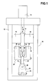
- This device 10 comprises a machine comprising firstly a carrier structure 12 generally constituted by a welded frame.
- This supporting structure 12 supports two holding systems 20 and 30.
- the first holding system 20 located in the lower part of the machine comprises a fixed column 29 which holds in position the counter-test tube 22.
- the counter-test piece 22 comprises a bore in which passes an axis 26 of the first holding system, axis through which the counter-test piece 22 is maintained regardless of the tensile stresses it receives.
- the second holding system 30 serves to maintain in position two half-test pieces 32.
- This second holding system 30 comprises a movable beam 39 set in reciprocating rectilinear translation movement in the vertical direction along the double arrow A by a linear actuator 14 or any other means of equivalent actuation.
- This beam 39 is guided in its reciprocating translation movement by the slides 16.
- the holding system 30 further comprises means for rigidly connecting the half-specimens 32 relative to the beam 39, which include the uprights 38 mentioned above.
- the characteristics of the linear actuator 14 are chosen so that it can print to the second holding system 30 relative to the first 20 translational movements which are representative of those made by a blade and more precisely the foot of the blade relative to the rotor disk during operation of the turbomachine to which the blade belongs. These movements are due to the considerable centrifugal forces received by the blades during the rotation of the engine, similar to a radial traction on the blade.
- the support structure 12 and the linear actuator 14 of the machine according to the invention it is possible to use standard components conventionally used in cyclic tensile testing machines. mechanical parts.
- the cycles to be reproduced generally have the following characteristics: Cycle number of up to 10,000 or 15,000 cycles; maximum applied force varying between 15,000 and 30,000 daN.
- the counter-test piece 22 comprises a hole 24 and the first holding system comprises an axis 26 through which the counter-test piece 22 is held regardless of the tensile stresses it receives.
- FIG. 2A is a sectional view showing the two half-test pieces 32, maintained on the one hand in the second holding system 30 (uprights 38), and on the other hand by the test-tube 22.
- the role of the second holding system 30 is to maintain the two half-test pieces and more precisely the bearing surfaces 24 thereof in front of the corresponding spans (ref.25, Fig.3 ) of the counter-test piece 22, and to transmit to the half-test pieces 32 an alternating translational movement with respect to the counter-test piece 22.
- the counter-test piece 22 at one of its ends (that of the top on the figure 1 ), has a relatively symmetrical bulb whose sides 23 project cantilevered on either side of its axis. Low external surfaces (in the sense of the figure 1 ) of these sides 23 are the contact surfaces or worn of the counter-test piece 22. These spans reproduce the shape of the rotor disc pin of the turbomachine on which the blade root is mounted.
- the counter-test piece 22 has fastening means, enabling it to be fixed on the test machine by means of first holding means for holding and securing the test-tube during the test-tests. traction.
- These holding means here comprise a bore 24, provided to pass a fixing axis of the test machine.
- the staves 24 of the half-test pieces 32 are located on the inclined upper faces of bulges 35 formed on the basis of the half-test pieces 32. These staves are contact surfaces. comparable to the litters of a dawn foot.
- the second holding system is biased in upward traction (in the sense of the figure 1 )
- the respective bearing surfaces 24 of the half-test pieces and 25 of the test-tube come into contact and thereby oppose the upward movement of the second holding system 30, which makes it possible to test, to put to the test the coating 34 deposited on the bearing surfaces 24 of the half-test pieces.
- the second holding system 30 comprises two uprights 38 parallel to the axis of traction and serving to hold the two half-test pieces, each being fixed to a half-test piece 32.
- This attachment can be made in particular by means of bolts 42.
- bolts 42 pass through on the one hand the amount 38 and are further fixed through the half-test piece 32 in a bore, an oblong or a oblong opening 41 as shown on the Figure 2B .
- the two uprights 38 can be fixed rigidly to one another or even to form a single piece, they advantageously can constitute independent parts of the second holding system 30.
- the two uprights 38 can deviate laterally relative to each other. This spacing is in the direction perpendicular to the direction of traction and perpendicular to the different scopes of the blade root. This degree of freedom makes it possible to better reproduce the conditions for maintaining the blade during operation.
- the spacing of the two parts of the holding system is limited by elastic return means.
- These elastic return means are constituted by four metal bars 40, which deform during the tensile cycles while remaining in their elastic deformation field. These bars 40 connect the uprights 38 in a direction perpendicular to the axis of traction. They are threaded at their free ends, so as to be fixed by bolting.
- the machine further comprises means 18 for measuring the spacing of the half-test pieces during the test. This measurement ensures the proper functioning and positioning of the various parts during the test.
- the half-test piece 32 is shown resting on the upright 38.
- the half-test piece 32 comprises a bearing surface 24 which extends between a point B and a point D.
- the test-tube also comprises a bearing surface 25, which faces the span 24 of the half-test piece 32.
- the span 24 of the half-test piece is coated with a coating of the same type and applied in the same method as the corresponding zone of the blade root.
- the position of this contact zone varies with respect to the range.
- the ranges of the test piece 22 and half-test piece 32 are arranged in a direction oblique or inclined with respect to the direction E, which is the direction of traction.
- This inclination is the one found in the attachment of the blade root on the rotor disc.
- the angle of inclination ⁇ is close to 45 °.
Abstract
Description
L'invention concerne le domaine des revêtements antifrictions appliqués sur des pieds d'aubes de machines tournantes, et le contrôle qualité de ceux-ci. Plus précisément, l'invention concerne un dispositif de test d'un revêtement susceptible de revêtir un pied d'aube de rotor de turbomachine. Il peut s'agir d'une turbomachine terrestre ou aéronautique, et notamment d'un turboréacteur ou d'un turbopropulseur d'avion.The invention relates to the field of anti-friction coatings applied on blade roots of rotating machines, and the quality control thereof. More specifically, the invention relates to a device for testing a coating capable of coating a turbine engine rotor blade root. It may be a land or aerospace turbomachine, and in particular a jet engine or an airplane turboprop.
Les aubes, et en particulier les aubes de soufflante dans les turbomachines aéronautiques sont des pièces mécaniques extrêmement sollicitées. Pour cette raison, le pied d'aube qui est la partie de maintien de l'aube est une partie particulièrement critique de la pièce. Le pied d'aube comporte des surfaces de contact avec le disque de rotor, ou portées, qui sont soumises en fonctionnement à des pressions et des températures élevées. Pour réduire les contraintes et notamment les contraintes de cisaillement qui sont appliquées sur les portées des pieds d'aube, on utilise de manière connue des revêtements antifrictions. Ces revêtements dits revêtements antifretting, peuvent être déposés notamment par projection thermique. Ils peuvent être multi-couches.The blades, and in particular the fan blades in the aerospace turbomachines are extremely stressed mechanical parts. For this reason, the blade root which is the part of holding the dawn is a particularly critical part of the piece. The blade root has contact surfaces with the rotor disk, or bearings, which are subjected to high pressure and temperature operation. In order to reduce the stresses and in particular the shear stresses that are applied to the root surfaces of the blade roots, anti-friction coatings are used in known manner. These so-called antifretting coatings can be deposited in particular by thermal spraying. They can be multi-layered.
Comme les défaillances sur les portées de pied d'aube, par exemple par apparition de fissures, sont un des modes principaux de défaillance des aubes, la qualité du revêtement antifrictions est essentielle. Pour s'assurer de la qualité de ce revêtement, et de la tenue de ce revêtement sur son interface avec l'aube elle-même, on procède de manière connue à des tests micrographiques, consistant à faire une coupe du revêtement et du pied d'aube et d'examiner au microscope l'aspect de cette coupe. Il est également connu de tester la qualité du revêtement par des tests standards de dureté, des tests d'adhérence en traction ou un cisaillement, ou encore d'effectuer des mesures d'épaisseurs.Since failures on the root feet, for example by cracking, are one of the main modes of blade failure, the quality of friction coating is essential. To ensure the quality of this coating, and the holding of this coating on its interface with the blade itself, is carried out in a known manner to micrographic tests, consisting of a cut of the coating and the foot of dawn and examine under the microscope the appearance of this cup. It is also known to test the quality of the coating by standard hardness tests, tensile adhesion tests or shear, or to measure thicknesses.
Parmi les tests connus figurent également les tests divulgués par les documents
Si l'on appelle cycle pour une aube (ou un pied d'aube) l'ensemble des sollicitations auxquelles celle-ci est soumise pendant une phase de fonctionnement (pendant un vol dans le cas d'un turboréacteur monté sur un avion), c'est-à-dire du démarrage jusqu'à l'arrêt, alors le constat précédent revient à dire que les tests actuels ne permettent pas de distinguer qualitativement les différents revêtements dès lors qu'ils résistent de manière satisfaisante à un certain nombre de cycles.If we call a cycle for a blade (or a blade root) all the stresses to which it is subjected during an operating phase (during a flight in the case of a turbojet mounted on an airplane), that is to say, from start to stop, then the previous observation amounts to saying that the current tests do not distinguish qualitatively different coatings when they resist satisfactorily a number of cycles.
Le but de l'invention est de définir un dispositif de test d'un revêtement susceptible de revêtir un pied d'aube de rotor de turbomachine, permettant la réalisation d'un test plus discriminant que les tests précédents quant à la qualité des revêtements testés, et dont les résultats soient fortement corrélés avec les constats réels de tenue dans le temps des revêtements de pieds d'aubes, tels que constatés sur l'ensemble de la vie d'une aube soit couramment de 10 000 à 15 000 cycles.The aim of the invention is to define a device for testing a coating capable of coating a turbine engine rotor blade root, enabling a more discriminating test to be performed than the previous tests as to the quality of the coatings tested. , and the results of which are strongly correlated with the real observations of the durability of blade root coatings, as seen throughout the life of a blade, are commonly from 10,000 to 15,000 cycles.
Ce but est atteint grâce au fait que le dispositif comprend deux demi-éprouvettes, chacune présentant une portée revêtue dudit revêtement, une contre-éprouvette présentant deux portées, et une machine comportant un premier système de maintien pour maintenir la contre-éprouvette suivant un axe de traction, un second système de maintien pour maintenir les demi-éprouvettes autour de la contre-éprouvette, et des moyens de traction pour soumettre les systèmes de maintien à des cycles de traction prédéterminés suivant l'axe de traction, pendant lesquels l'effort de traction est transmis d'un système de maintien à l'autre via les portées respectives en contact de la contre-éprouvette et des demi-éprouvettes ; et que le second système de maintien comporte des moyens de rappel élastique autorisant l'écartement des deux demi-éprouvettes dans une direction perpendiculaire à la direction de traction en réponse à une force d'écartement exercée sur ces deux demi-éprouvettes par la contre-éprouvette lors d'un cycle de traction.This object is achieved by virtue of the fact that the device comprises two half-test pieces, each having a bearing surface coated with said coating, a counter-test piece having two bearing surfaces, and a machine comprising a first holding system for holding the test-tube along an axis. a second holding system for holding the half-specimens around the counter-specimen, and traction means for subjecting the holding systems to predetermined traction cycles along the axis of traction, during which the force traction is transmitted from one holding system to the other via the respective bearing surfaces in contact with the test-tube and half-test pieces; and that the second holding system comprises elastic return means permitting the spacing of the two half-specimens in a direction perpendicular to the direction of traction in response to a spreading force exerted on these two half-specimens by the counter-force. test piece during a traction cycle.
Le principe du test ainsi défini est fondamentalement différent des tests précédemment connus. En effet, il consiste à soumettre des éprouvettes revêtues à des tests de fatigue représentatifs des sollicitations auxquelles les pieds d'aubes sont exposés pendant la vie de l'aube. Avantageusement, le dispositif ne nécessite pas l'utilisation d'aubes réelles mais simplement l'utilisation de demi-éprouvettes, chacune présentant une portée couverte du revêtement à tester. On notera qu'il est parfaitement possible en outre que chaque demi-éprouvette présente non seulement une, mais plusieurs portées, la contre-éprouvette comportant alors une portée correspondant à chacune de ces portées des deux demi-éprouvettes.The principle of the test thus defined is fundamentally different from the previously known tests. Indeed, it consists in subjecting coated test pieces to fatigue tests representative of the stresses to which the blade roots are exposed during the life of the dawn. Advantageously, the device does not require the use of actual vanes but simply the use of half-specimens, each having a scope covered with the coating to be tested. Note that it is perfectly possible furthermore that each half-test piece has not only one but several scopes, the counter-test then having a bearing corresponding to each of these scopes of the two half-test pieces.
Les premier et second systèmes de maintien maintiennent respectivement les demi-éprouvettes et la contre-éprouvette en regard les unes de l'autre, de manière à faire coïncider leurs portées. Les systèmes de maintien sont alors soumis à des mouvements de traction relatifs l'un par rapport à l'autre par des moyens connus, de manière à soumettre les portées et notamment les portées des demi-éprouvettes à des sollicitations représentatives de celles qu'éprouve un pied d'aube en fonctionnement.The first and second holding systems respectively hold the half-test pieces and the counter-test-piece facing each other, so as to make their litters coincide. The holding systems are then subjected to tensile movements relative to one another by known means, so as to subject the bearing surfaces and in particular the bearing surfaces of the half-samples to solicitations representative of those experienced by a dawn foot in operation.
Ces sollicitations sont simulées par des cycles de traction au cours desquels on impose à la contre-éprouvette des efforts dans la direction de traction. Ces efforts varient en fonction du temps suivant un cycle prédéterminé, dit cycle de traction. Préférentiellement, pour chaque cycle de traction, on fait croître la traction depuis une valeur initiale nulle, ou du moins faible (par rapport à la valeur maximale) jusqu'à une valeur maximale, puis l'on revient à la valeur initiale. La valeur initiale et la valeur maximale peuvent éventuellement, l'une et/ou l'autre indépendamment, être maintenues pendant une certaine durée. Naturellement, d'autres profils de cycles de traction sont envisageables, selon la manière dont on veut simuler les différentes phases de fonctionnement de la turbomachine. Le paramètre de vitesse de montée en charge, c'est-à-dire l'augmentation de la force de traction par unité de temps, peut aussi être utilisé comme variable susceptible d'être optimisée.These stresses are simulated by tensile cycles in which the counter-test is imposed with forces in the direction of traction. These forces vary according to the time following a predetermined cycle, called the traction cycle. Preferably, for each traction cycle, the traction is increased from a zero initial value, or at least a small value (relative to the maximum value) up to a maximum value, then it returns to the initial value. The initial value and the maximum value may optionally, one and / or the other independently, be maintained for a certain duration. Naturally, other traction cycle profiles are possible, depending on how one wants to simulate the different phases of operation of the turbomachine. The load ramp rate parameter, i.e. the increase of the tensile force per unit of time, can also be used as a variable that can be optimized.
De manière connue, la fixation d'une aube sur un disque rotor est faite en général par un accouplement tenon/mortaise formant une attache. Cette attache est constituée par un tenon aménagé sur une extrémité radialement intérieure de l'aube, le pied d'aube, qui est fixé dans une mortaise prévue sur la périphérie du disque rotor. Les pieds d'aubes d'une part, les tenons ou protubérances de disque rotor formés entre les mortaises de disque rotor d'autre part, ont ainsi respectivement des formes complémentaires en queue d'aronde, et sont disposés radialement en sens opposé de manière à assurer la fixation mutuelle entre les aubes et le disque rotor.In known manner, the attachment of a blade on a rotor disk is generally made by a mortise / tenon coupling forming a fastener. This attachment consists of a tenon arranged on a radially inner end of the blade, the blade root, which is fixed in a mortise provided on the periphery of the rotor disc. The blade roots, on the one hand, the tenons or protuberances of the rotor disc formed between the rotor disk mortises on the other hand, and have respectively complementary dovetail shapes, and are arranged radially in opposite directions so as to ensure mutual attachment between the blades and the rotor disc.
Dans une roue à aubes, les aubes sont régulièrement attachées sur la périphérie extérieure du disque rotor, qui comporte ainsi autant d'alvéoles de fixation et de tenons en queue d'aronde qu'il y a d'aubes à fixer.In a paddle wheel, the blades are regularly attached to the outer periphery of the rotor disk, which thus has as many attachment cells and dovetail tenons as there are blades to be fixed.
Les attaches des aubes sur le disque rotor forment ainsi un motif qui se répète dans le sens circonférentiel et qui comprend le tenon en queue d'aronde du disque rotor avec les deux demi-pieds d'aubes qui enserrent celui-ci dans la roue à aubes. C'est ce motif que reproduit la contre-éprouvette enserrée par les deux demi-éprouvettes.The blades of the blades on the rotor disk thus form a pattern which repeats in the circumferential direction and which comprises the dovetail pin of the rotor disk with the two half-feet of blades which enclose it in the wheel to blades. It is this motive that reproduces the counter-specimen enclosed by the two half-specimens.
Comme cela a été dit, dans la machine de test intégrée au dispositif, le second système de maintien comporte des moyens de rappel élastique autorisant l'écartement des deux demi-éprouvettes dans une direction perpendiculaire à la direction de traction en réponse à une force d'écartement exercée sur ces deux demi-éprouvettes par la contre-éprouvette lors d'un cycle de traction. En effet, pendant un cycle de traction, notamment lorsque les portées des demi-éprouvettes et/ou de la contre-éprouvette sont obliques, la contre-éprouvette appuie sur les demi-éprouvettes, et peut tendre à écarter les demi-éprouvettes dans une direction transversale, perpendiculaire à la direction de traction. Pour empêcher cela, avantageusement le second système de maintien comporte les moyens de rappel élastique précités, qui permettent de maintenir des positions relatives de la contre-éprouvette et des demi-éprouvettes qui soient représentatives des positions réelles du pied d'aube et d'un tenon de disque de rotor dans une turbomachine.As has been said, in the test machine integrated into the device, the second holding system comprises elastic return means permitting the spacing of the two half-specimens in a direction perpendicular to the direction of traction in response to a force of the spacing exerted on these two half-test pieces by the counter-test piece during a traction cycle. Indeed, during a tensile cycle, especially when the bearing surfaces of the half-test pieces and / or the counter-test piece are oblique, the counter-test piece presses the half-test pieces, and can tend to move the half-test pieces in a transverse direction, perpendicular to the direction of traction. To prevent this, advantageously the second holding system comprises the aforementioned elastic return means, which allow to maintain relative positions of the test-tube and half-test pieces which are representative of the actual positions of the blade root and a rotor disk stud in a turbomachine.
Selon un mode de réalisation, les portées des demi-éprouvettes sont obliques par rapport à l'axe de traction, de manière à être représentatives de la forme des portées d'un pied d'aube de rotor de turbomachine. Ainsi, l'angle formé par la portée des demi-éprouvettes est représentatif de celui que forme une portée de pied d'aube dans une turbomachine par rapport à la direction radiale de celui-ci. Avantageusement, l'angle des portées par rapport à la direction de traction peut être voisin de 45 ° ; plus généralement, cet angle peut varier entre 30 et 60°.According to one embodiment, the scopes of the half-specimens are oblique with respect to the axis of traction, so as to be representative of the shape of the staves of a turbine engine rotor blade root. Thus, the angle formed by the range of the half-test pieces is representative of that formed by a blade root surface in a turbomachine with respect to the radial direction of the latter. Advantageously, the angle of the raised relative to the direction of traction may be close to 45 °; more generally, this angle can vary between 30 and 60 °.
En outre, les demi-éprouvettes peuvent être représentatives d'un pied d'aube non seulement par la forme de leurs portées, mais aussi par leur matériau. Ainsi, habituellement on fabrique les demi-éprouvettes dans le même matériau que le pied d'aube, typiquement dans un alliage à base de titane ou de nickel.In addition, the half-test pieces may be representative of a blade root not only by the shape of their bearings, but also by their material. Thus, usually half-test pieces are made in the same material as the blade root, typically in a titanium-based or nickel-based alloy.
Pour les mêmes raisons, on peut également choisir un matériau identique à celui du disque de rotor pour la contre-éprouvette, soit également dans un alliage à base de titane ou de nickel. Cela permet une représentation plus fidèle du comportement du pied d'aube par rapport au disque de rotor.For the same reasons, it is also possible to choose a material identical to that of the rotor disc for the counter-test piece, or else in a titanium or nickel-based alloy. This allows a more accurate representation of the behavior of the blade root relative to the rotor disk.
Selon un mode de réalisation, les portées de la contre-éprouvette sont obliques par rapport à l'axe de traction de manière à être représentatives de la forme des portées d'un tenon d'un disque de rotor de turbomachine. Ainsi, l'angle formé par la portée de la contre-éprouvette est représentatif de celui que forme une portée de tenon de disque de rotor dans une turbomachine par rapport à la direction radiale de celui-ci. De ce fait, la sollicitation que la portée de la contre-éprouvette applique à la demi-éprouvette est représentative de celle que la portée d'un tenon de disque de rotor applique à la portée du pied d'aube, dans une turbomachine. De préférence, les portées de la contre-éprouvette sont inclinées d'un angle compris entre 30 et 60°, et l'on retient en général un angle voisin de 45°.According to one embodiment, the surfaces of the counter-test piece are oblique with respect to the axis of traction so as to be representative of the shape of the bearing surfaces of a stud of a turbomachine rotor disk. Thus, the angle formed by the range of the counter-test specimen is representative of that formed by a rotor disk stud surface in a turbomachine with respect to the radial direction thereof. As a result, the fact that the range of the counter-test piece applies to the half-test piece is representative of that which the range of a rotor disk stud applies to the blade root reach in a turbomachine. Preferably, the surfaces of the counter-test piece are inclined at an angle of between 30 and 60 °, and an angle close to 45 ° is generally retained.
Selon un mode de réalisation, les moyens de rappel élastique comportent au moins un barreau constitué d'un matériau élastique, se déformant tout en restant dans son domaine de déformation élastique pendant les cycles de traction. Le barreau possède ainsi une certaine capacité de déformation, qui permet à la machine de représenter, de simuler les déformations effectivement constatées en fonctionnement dans la turbomachine, que ce soient les déformations du pied d'aube et/ou du tenon du disque de rotor. Grâce à cette possibilité d'écartement des deux demi-éprouvettes, la représentativité des résultats obtenus grâce au dispositif de test est encore augmentée.According to one embodiment, the elastic return means comprise at least one bar made of an elastic material, deforming while remaining in its elastic deformation range during the traction cycles. The bar thus has a certain capacity of deformation, which allows the machine to represent, to simulate the deformations actually found in operation in the turbomachine, that is the deformations of the blade root and / or the tenon of the rotor disk. With this possibility of separation of the two half-test pieces, the representativity of the results obtained by the test device is further increased.
Selon une variante du mode de réalisation précédent, le second système de maintien comporte deux montants parallèles à l'axe de traction et servant à maintenir les deux demi-éprouvettes, ledit barreau reliant ces montants suivant une direction perpendiculaire à l'axe de traction. Les deux montants parallèles à l'axe de traction, au voisinage des demi-éprouvettes, permettent de garantir le maintien en position de celles-ci pendant les cycles de traction. Il est pour cela préférable que les demi-éprouvettes soient relativement allongées, pour faciliter leur blocage en rotation.According to a variant of the previous embodiment, the second holding system comprises two posts parallel to the axis of traction and serving to maintain the two half-test pieces, said bar connecting these amounts in a direction perpendicular to the axis of traction. The two uprights parallel to the axis of traction, in the vicinity of the half-test pieces, make it possible to guarantee that these are held in position during the pulling cycles. It is therefore preferable that the half-test pieces are relatively elongated, to facilitate their locking in rotation.
D'autre part, comme les efforts d'écartement dans une direction transversale à la direction de traction passent par ledit au moins un barreau, on peut dimensionner celui-ci facilement en fonction des efforts d'extension qu'il est amené à subir et de l'allongement considéré comme admissible sous l'effet de ces efforts.On the other hand, as the spacing forces in a direction transverse to the direction of traction pass through said at least one bar, it can be dimensioned easily as a function of the extension forces that it is required to undergo and the elongation considered permissible under the effect of these efforts.
Selon une variante du mode de réalisation précédent, le dispositif de test comporte en outre des moyens de mesure de l'écartement des demi-éprouvettes pendant l'essai. Il est ainsi possible à tout moment de s'assurer que les positions relatives de la contre-éprouvette et des demi-éprouvettes correspondent bien à ce qui a été envisagé.According to a variant of the previous embodiment, the test device further comprises means for measuring the spacing of the half-test pieces during the test. It is thus possible at any time to ensure that the relative positions of the test-tube and half-test pieces correspond to what has been envisaged.
Selon un mode de réalisation, les demi-éprouvettes ont au voisinage de leurs portées une forme représentative de demi-pieds d'aubes de rotor de turbomachine, et l'axe de traction est disposé sensiblement suivant la direction radiale des demi-pieds d'aubes. Cette disposition permet que les demi-éprouvettes soient testées dans des conditions reproduisant fidèlement les conditions de fonctionnement et de sollicitation réelles. De plus, la simulation du comportement du revêtement pour pied d'aube ne se limite pas à la zone proprement dite du revêtement, mais intègre la partie du pied d'aube située au voisinage de la ou des portées.According to one embodiment, the half-test pieces have, in the vicinity of their seats, a representative form of half-feet of turbomachine rotor blades, and the traction axis is arranged substantially in the radial direction of the half-feet of the turbine. blades. This arrangement allows half test pieces to be tested under conditions that faithfully reproduce actual operating and stress conditions. In addition, the simulation of the behavior of the blade foot coating is not limited to the actual area of the coating, but integrates the blade root portion located in the vicinity of the or litters.
Selon un mode de réalisation, de même la contre-éprouvette a au voisinage de ses portées une forme représentative de la forme d'un tenon d'un disque de rotor de turbomachine. Dans ce cas, l'action de la contre-éprouvette qui reproduit celle du tenon de disque de rotor sur le pied d'aube est plus réaliste, car elle est apte à reproduire le comportement du tenon de disque de rotor, non seulement dans le voisinage immédiat de la ou des portées, mais sur toute la partie du tenon située au voisinage des portées, c'est-à-dire habituellement toute l'extrémité de la contre-éprouvette en forme de tenon.According to one embodiment, likewise the counter-test piece has in the vicinity of its seats a form representative of the shape of a stud of a turbomachine rotor disc. In this case, the action of the counter-test specimen, which reproduces that of the rotor disc stud on the blade root, is more realistic, since it is able to reproduce the behavior of the rotor disc stud, not only in the immediate vicinity of the one or more staves, but over the entire portion of the tenon located in the vicinity of the staves, that is to say usually the entire end of the stud-shaped test-tube.
On notera que dans le dispositif, de manière plus ou moins fidèle suivant le mode de réalisation retenu, les demi-éprouvettes qui se font face sont assimilables aux faces opposées d'un pied d'aube, la contre-éprouvette étant pour sa part assimilable au tenon du disque de rotor servant à fixer l'aube sur le rotor. Ainsi, alors que sur une turbomachine c'est le pied d'aube qui est enserré et fixé entre deux tenons du disque de rotor, en revanche, dans la machine de test ce sont les deux demi-éprouvettes qui enserrent de part et d'autre une contre-éprouvette représentant un tenon du disque de rotor. Il a été constaté que malgré cette disposition apparemment inversée, une excellente représentativité des résultats est obtenue.It will be noted that in the device, in a more or less faithful manner according to the embodiment chosen, the half-test pieces facing each other are comparable to the opposite faces of a blade root, the counter-test-tube being for its part comparable to the pin of the rotor disc used to fix the blade on the rotor. Thus, while on a turbomachine is the blade root which is clamped and fixed between two tenons of the rotor disk, however, in the test machine are the two half-test tubes which enclose the part and another counter-specimen representing a tenon of the rotor disc. It has been found that despite this seemingly reversed disposition, excellent representativeness of the results is obtained.
Selon un mode de réalisation, le côté des demi-éprouvettes situé du côté de la contre-éprouvette est sans contre-dépouille. Celles-ci sont donc économiques car elles peuvent être usinées simplement en usinage 3 axes. Il en va de même pour la contre-éprouvette. Les demi-éprouvettes peuvent même en outre être de forme extérieure convexe du côté de la contre-éprouvette.According to one embodiment, the half-specimen side located on the side of the test-tube is without undercut. These are therefore economical because they can be machined simply in 3-axis machining. The same goes for the counter-specimen. The half-test pieces may even be of external convex shape on the side of the test-tube.
Enfin, on notera qu'en outre, les déplacements des éprouvettes suivant la direction de traction peuvent être mesurés et enregistrés par un système de mesure de déplacement comme un comparateur ou une jauge.Finally, it will be noted that in addition, the movements of the specimens in the direction of traction can be measured and recorded by a displacement measuring system such as a comparator or a gauge.
L'invention sera bien comprise et ses avantages apparaîtront mieux à la lecture de la description détaillée qui suit, de modes de réalisation représentés à titre d'exemples non limitatifs. La description se réfère aux dessins annexés, sur lesquels :
- la
figure 1 est une vue en coupe axiale d'un dispositif de test selon l'invention ; - les
figures 2A et 2B sont des vues en coupe de la partie centrale de ce dispositif, respectivement de face et de côté ; et - la
figure 3 est une vue en coupe axiale des zones de portées de la contre-éprouvette et des demi-éprouvettes du dispositif de test.
- the
figure 1 is an axial sectional view of a test device according to the invention; - the
Figures 2A and 2B are sectional views of the central part of this device, respectively front and side; and - the
figure 3 is an axial sectional view of the bearing areas of the test-tube and half-test pieces of the test device.
En faisant référence à la
Le premier système de maintien 20 situé dans la partie basse de la machine comporte une colonne fixe 29 qui maintient en position la contre-éprouvette 22. La contre-éprouvette 22 comporte un perçage dans lequel passe un axe 26 du premier système de maintien, axe grâce auquel la contre-éprouvette 22 est maintenue quelles que soient les sollicitations en traction qu'elle reçoit.The
Le deuxième système de maintien 30 sert à maintenir en position deux demi-éprouvettes 32. Ce deuxième système de maintien 30 comporte une poutre mobile 39 mise en mouvement alternatif de translation rectiligne dans la direction verticale suivant la double flèche A par un actuateur linéaire 14 ou tout autre moyen d'actuation équivalent. Cette poutre 39 est guidée dans son mouvement alternatif de translation par les glissières 16. Le système de maintien 30 comporte en outre des moyens pour lier rigidement les demi-éprouvettes 32 par rapport à la poutre 39, qui comportent notamment les montants 38 cités précédemment.The
Les caractéristiques de l'actuateur linéaire 14 sont choisies de telle sorte que celui-ci puisse imprimer au deuxième système de maintien 30 par rapport au premier 20 des mouvements de translation qui sont représentatifs de ceux qu'effectue une aube et plus précisément le pied de l'aube par rapport au disque de rotor pendant le fonctionnement de la turbomachine à laquelle l'aube appartient. Ces mouvements sont dus aux forces centrifuges considérables reçues par les aubes lors de la rotation du moteur, assimilables à une traction radiale sur l'aube.The characteristics of the
Habituellement, on cherche à reproduire les conditions de fonctionnement du pied d'aube, aussi bien par les efforts notamment radiaux qui lui sont imposés, que par l'amplitude des mouvements du pied d'aube. L'amplitude de ces derniers mouvements dépend des pièces qui interagissent avec le pied d'aube ; celles-ci sont donc de grande importance pour la qualité du test. Dans la machine présentée, ces pièces sont d'un côté les montants de maintien 38, et de l'autre côté (sur le côté interne), la contre-éprouvette 22 qui est assimilable au tenon du disque de rotor, chargée dans une turbomachine de maintenir les aubes. On notera cependant que le dispositif peut être utilisé pour tester les revêtements dans des directions, ou avec des forces de traction, qui soient différentes des conditions habituelles de sollicitation du pied d'aube et de ses portées.Usually, it seeks to reproduce the operating conditions of the blade root, both by the particular radial forces imposed on it, as the amplitude of the movements of the blade root. The amplitude of these last movements depends on the parts that interact with the blade root; these are therefore of great importance for the quality of the test. In the machine shown, these parts are on one side the holding posts 38, and on the other side (on the inner side), the
Pour la structure porteuse 12 et l'actuateur linéaire 14 de la machine selon l'invention, on peut utiliser des composants standards utilisés habituellement dans des machines de test cyclique en traction de pièces mécaniques. Les cycles à reproduire ont généralement les caractéristiques suivantes : Nombre de cycle pouvant aller jusqu'à 10 000 ou 15 000 cycles ; force maximale appliquée variant entre 15 000 et 30 000 daN.For the
La contre-éprouvette 22 comporte un trou 24 et le premier système de maintien comporte un axe 26 par lequel la contre-éprouvette 22 est maintenue quelles que soient les sollicitations en traction qu'elle reçoit.The
Enfin, les déplacements relatifs des demi-éprouvettes par rapport à la contre-éprouvette sont mesurés et enregistrés par un système de mesure 19.Finally, the relative movements of the half-test pieces relative to the test-tube are measured and recorded by a measuring
En faisant référence aux
La contre-éprouvette 22, à l'une de ses extrémités (celle du haut sur la
Les portées 24 des demi-éprouvettes 32 se trouvent sur les faces supérieures inclinées de renflements 35 formés sur la base des demi-éprouvettes 32. Ces portées sont des surfaces de contact assimilables aux portées d'un pied d'aube. Lorsque le deuxième système de maintien est sollicité en traction vers le haut (au sens de la
Alors que les demi-éprouvettes 32 et la contre-éprouvette 22 sont consommées par les essais puisque l'essai conduit à leur déformation, en revanche les autres pièces de la machine sont des pièces réutilisables.While the half-
Le second système de maintien 30 comporte deux montants 38 parallèles à l'axe de traction et servant à maintenir les deux demi-éprouvettes, chacun étant fixé à une demi-éprouvette 32. Cette fixation peut être faite notamment grâce à des boulons 42. Les boulons 42 traversent d'une part le montant 38 et sont de plus fixés à travers la demi-éprouvette 32 dans un perçage, un oblong ou encore un oblong débouchant 41 comme représenté sur la
Même s'il est possible que les deux montants 38 soient fixés rigidement l'un à l'autre ou même ne forment qu'une pièce unique, en revanche avantageusement ils peuvent constituer des parties indépendantes du deuxième système de maintien 30.Although it is possible for the two
Par deux parties indépendantes, il faut comprendre ici que les deux montants 38 peuvent s'écarter latéralement l'un par rapport à l'autre. Cet écartement se fait dans la direction perpendiculaire à la direction de traction et perpendiculaire aux différentes portées du pied d'aube. Ce degré de liberté permet de mieux reproduire les conditions de maintien de l'aube en fonctionnement.By two independent parts, it should be understood here that the two
Avantageusement, l'écartement des deux parties du système de maintien est limité par des moyens de rappel élastique. Ces moyens de rappel élastique sont constitués par quatre barreaux métalliques 40, qui se déforment pendant les cycles de traction tout en restant dans leur domaine de déformation élastique. Ces barreaux 40 relient les montants 38 suivant une direction perpendiculaire à l'axe de traction. Ils sont filetés à leurs extrémités libres, de manière à être fixés par boulonnage.Advantageously, the spacing of the two parts of the holding system is limited by elastic return means. These elastic return means are constituted by four
Pour contrôler le bon fonctionnement des cycles de traction auxquels sont soumis les pieds d'aube, la machine comporte en outre des moyens 18 de mesure de l'écartement des demi-éprouvettes pendant l'essai. Cette mesure permet de s'assurer du bon fonctionnement et du bon positionnement des différentes pièces au cours de l'essai.In order to check the correct operation of the traction cycles to which the blade roots are subjected, the machine further comprises means 18 for measuring the spacing of the half-test pieces during the test. This measurement ensures the proper functioning and positioning of the various parts during the test.
En faisant référence à la
Comme on le voit sur la
Claims (11)
- A device (10) for testing a coating (36) capable of coating a turbomachine rotor blade root, said device comprising two test piece halves (32), each having a bearing surface (24) coated with said coating, one counter test piece (22) having two bearing surfaces (25), and a test machine comprising a first holding system (20) for holding the counter test piece (22) along a tensile axis (A), a second holding system (30) for holding the test piece halves (32) around the counter test piece (22), tensile means (14) for subjecting the holding systems to predetermined tensile cycles along the tensile axis, during which tensile strain is transmitted from one holding system to the other via the respective bearing surfaces (25, 24) contacting each other of the counter test piece and the test piece halves; said device being characterized in that the second holding system comprises resilient return means (40) allowing for the two test piece halves to open up in a direction perpendicular to the tensile direction in response to an opening force applied to these two test piece halves by the counter test piece during a tensile cycle.
- The test device according to claim 1, characterized in that the side of the test piece halves (32) located on the side of the counter test piece (22) has no undercut.
- The test device according to claim 1 or 2, characterized in that the bearing surfaces (24) of the test piece halves are sloping with respect to the tensile axis, so as to represent the shape of the bearing surfaces of a turbomachine rotor blade root.
- The test device according to any of claims 1 to 3, characterized in that the bearing surfaces (25) of the counter test piece (22) are sloping with respect to the tensile axis, so as to represent the shape of the bearing surfaces of a turbomachine rotor disk tenon.
- The test device according to any of claims 1 to 4, characterized in that said resilient return means comprise at least one bar (40) of resilient material, deforming while remaining in its range of elastic deformation during tensile cycles.
- The test device according to any of claims 1 to 5, characterized in that the second holding system (30) comprises two posts (38) parallel to the tensile axis and used for holding the two test piece halves (32), said bar connecting these posts according to a direction perpendicular to the tensile axis.
- The test device according to any of claims 1 to 6, characterized in that it further comprises means (18) for measuring the space between the test piece halves during testing.
- The test device according to any of claims 1 to 7, characterized in that the test piece halves (32) have close to the bearing surfaces thereof a shape representing turbomachine rotor blade root halves, and the tensile axis is arranged substantially in the radial direction of the blade root halves.
- The test device according to any of claims 1 to 8, characterized in that the counter test piece (22) has close to the bearing surfaces thereof a shape representing the shape of a tenon of a turbomachine rotor disk.
- The test device according to any of claims 1 to 9, characterized in that the counter test piece is formed of a titanium or nickel base alloy.
- The test device according to any of claims 1 to 10, characterized in that the test piece halves are formed of a titanium or nickel base alloy.
Applications Claiming Priority (2)
| Application Number | Priority Date | Filing Date | Title |
|---|---|---|---|
| FR0851183A FR2927998A1 (en) | 2008-02-25 | 2008-02-25 | TESTING MACHINE FOR A WAVE FOOT COATING. |
| PCT/FR2009/050296 WO2009112757A1 (en) | 2008-02-25 | 2009-02-25 | Device for testing the coating of a vane base |
Publications (2)
| Publication Number | Publication Date |
|---|---|
| EP2247936A1 EP2247936A1 (en) | 2010-11-10 |
| EP2247936B1 true EP2247936B1 (en) | 2011-08-31 |
Family
ID=39900868
Family Applications (1)
| Application Number | Title | Priority Date | Filing Date |
|---|---|---|---|
| EP09720983A Active EP2247936B1 (en) | 2008-02-25 | 2009-02-25 | Device for testing the coating of a vane base |
Country Status (11)
| Country | Link |
|---|---|
| US (1) | US8408068B2 (en) |
| EP (1) | EP2247936B1 (en) |
| JP (1) | JP5265707B2 (en) |
| CN (1) | CN101960284B (en) |
| AT (1) | ATE522799T1 (en) |
| BR (1) | BRPI0907536B1 (en) |
| CA (1) | CA2716242C (en) |
| ES (1) | ES2372265T3 (en) |
| FR (1) | FR2927998A1 (en) |
| RU (1) | RU2489702C2 (en) |
| WO (1) | WO2009112757A1 (en) |
Families Citing this family (8)
| Publication number | Priority date | Publication date | Assignee | Title |
|---|---|---|---|---|
| GB2472193A (en) * | 2009-07-27 | 2011-02-02 | Rolls Royce Plc | Rotor blade test specimen |
| CN102207437B (en) * | 2011-03-04 | 2013-04-03 | 立邦涂料(中国)有限公司 | Device for testing elastic coating and test method thereof |
| FR3005734B1 (en) * | 2013-05-17 | 2016-01-29 | Snecma | OPTIMIZATION OF A TEST BENCH IN OLIGOCYCLIC FATIGUE OR IN OLIGOCYCLIC AND POLYCYCLIC FATIGUE |
| FR3005733B1 (en) * | 2013-05-17 | 2015-04-24 | Snecma | TEST BENCH IN OLIGOCYCLIC FATIGUE OR IN OLIGOCYCLIC AND POLYCYCLIC FATIGUE |
| CN104568619B (en) * | 2014-12-24 | 2017-04-05 | 西南交通大学 | A kind of normal direction charger of fretting fatigue testing system |
| CN107024386B (en) * | 2017-04-27 | 2019-04-23 | 北京航空航天大学 | The experimental rig applied for blade loading |
| KR102366031B1 (en) * | 2017-06-15 | 2022-02-22 | 삼성디스플레이 주식회사 | Apparatus for testing shear stress |
| JP7093063B2 (en) * | 2019-04-12 | 2022-06-29 | 株式会社Ihi | Vibration test jig for rotor blades |
Family Cites Families (26)
| Publication number | Priority date | Publication date | Assignee | Title |
|---|---|---|---|---|
| US3802255A (en) * | 1972-03-08 | 1974-04-09 | Us Air Force | Fixture for tensile and stress rupture testing of turbine blades |
| US4541287A (en) * | 1983-03-28 | 1985-09-17 | The United States Of America As Represented By The United States Department Of Energy | Method of measuring metal coating adhesion |
| JPS6257146U (en) * | 1985-09-28 | 1987-04-09 | ||
| JPH03251735A (en) * | 1990-02-28 | 1991-11-11 | Shimadzu Corp | Chucking tool for test piece |
| JP2506684Y2 (en) * | 1990-04-27 | 1996-08-14 | 株式会社島津製作所 | Material testing machine |
| JP2522822Y2 (en) * | 1990-05-22 | 1997-01-16 | 株式会社島津製作所 | Material testing machine |
| US5160243A (en) * | 1991-01-15 | 1992-11-03 | General Electric Company | Turbine blade wear protection system with multilayer shim |
| US5240375A (en) * | 1992-01-10 | 1993-08-31 | General Electric Company | Wear protection system for turbine engine rotor and blade |
| JP2586080Y2 (en) * | 1992-03-31 | 1998-12-02 | 株式会社島津製作所 | Material testing machine |
| RU2089878C1 (en) * | 1993-12-06 | 1997-09-10 | Шелест Сергей Орестович | Method and device for measuring erosion wear of turbine rotor blade edges |
| EP0750689B1 (en) * | 1994-03-17 | 2002-09-04 | The Westaim Corporation | Low friction cobalt-based coatings for titanium |
| US6267558B1 (en) * | 1999-05-26 | 2001-07-31 | General Electric Company | Dual intensity peening and aluminum-bronze wear coating surface enhancement |
| US6250166B1 (en) * | 1999-06-04 | 2001-06-26 | General Electric Company | Simulated dovetail testing |
| US6290466B1 (en) * | 1999-09-17 | 2001-09-18 | General Electric Company | Composite blade root attachment |
| JP2001337016A (en) * | 2000-05-29 | 2001-12-07 | Ishikawajima Harima Heavy Ind Co Ltd | Dovetail fixing structure of tensile tester |
| JP2002310867A (en) * | 2001-04-16 | 2002-10-23 | Hitachi Ltd | Fretting corrosion fatigue evaluation method |
| FR2841609B1 (en) * | 2002-06-27 | 2004-09-10 | Snecma Moteurs | BLOWER RETAINER LEVEL RETAINER |
| FR2844562B1 (en) * | 2002-09-18 | 2004-10-29 | Snecma Moteurs | CONTROL OF THE AXIAL POSITION OF A BLOWER ROTOR BLADE |
| US7144602B2 (en) * | 2003-04-25 | 2006-12-05 | Snecma Moteurs | Process for obtaining a flexible/adaptive thermal barrier |
| GB0410967D0 (en) * | 2004-05-17 | 2004-06-16 | Rolls Royce Plc | An apparatus and method for fatigue testing |
| FR2872884B1 (en) * | 2004-07-07 | 2006-11-10 | Snecma Moteurs Sa | METHOD FOR PROTECTING CONTACT SURFACES BETWEEN TWO METALLIC PARTS BENEFITING FROM SUCH PROTECTION |
| FR2883574B1 (en) * | 2005-03-23 | 2008-01-18 | Snecma Moteurs Sa | "THERMAL PROJECTION DEPOSITION METHOD OF ANTI-WEAR COATING" |
| CN100489524C (en) * | 2005-07-21 | 2009-05-20 | 北京航空航天大学 | Thermal barrier coating service environment simulation device and method for stimulating environmental control |
| JP4692462B2 (en) * | 2006-10-12 | 2011-06-01 | 株式会社Ihi | Sliding structure and film forming method |
| RU2339930C1 (en) * | 2007-04-24 | 2008-11-27 | Федеральное государственное унитарное предприятие "Центральный институт авиационного моторостроения имени П.И. Баранова" | Method of determining strength properties of high-temperature heat-insulating coatings and device to this effect |
| FR2927997A1 (en) * | 2008-02-25 | 2009-08-28 | Snecma Sa | METHOD FOR TESTING A WAVE FOOT COATING |
-
2008
- 2008-02-25 FR FR0851183A patent/FR2927998A1/en not_active Withdrawn
-
2009
- 2009-02-25 WO PCT/FR2009/050296 patent/WO2009112757A1/en active Application Filing
- 2009-02-25 CA CA2716242A patent/CA2716242C/en active Active
- 2009-02-25 US US12/919,017 patent/US8408068B2/en active Active
- 2009-02-25 AT AT09720983T patent/ATE522799T1/en not_active IP Right Cessation
- 2009-02-25 ES ES09720983T patent/ES2372265T3/en active Active
- 2009-02-25 BR BRPI0907536-4A patent/BRPI0907536B1/en active IP Right Grant
- 2009-02-25 CN CN200980106374.9A patent/CN101960284B/en active Active
- 2009-02-25 RU RU2010139414/28A patent/RU2489702C2/en active
- 2009-02-25 EP EP09720983A patent/EP2247936B1/en active Active
- 2009-02-25 JP JP2010547236A patent/JP5265707B2/en active Active
Also Published As
| Publication number | Publication date |
|---|---|
| ES2372265T3 (en) | 2012-01-17 |
| BRPI0907536A2 (en) | 2015-07-28 |
| JP5265707B2 (en) | 2013-08-14 |
| CN101960284A (en) | 2011-01-26 |
| FR2927998A1 (en) | 2009-08-28 |
| JP2011513701A (en) | 2011-04-28 |
| US8408068B2 (en) | 2013-04-02 |
| CA2716242A1 (en) | 2009-09-17 |
| US20110000308A1 (en) | 2011-01-06 |
| CN101960284B (en) | 2013-06-05 |
| RU2010139414A (en) | 2012-04-10 |
| CA2716242C (en) | 2016-07-12 |
| ATE522799T1 (en) | 2011-09-15 |
| BRPI0907536B1 (en) | 2019-05-07 |
| EP2247936A1 (en) | 2010-11-10 |
| RU2489702C2 (en) | 2013-08-10 |
| WO2009112757A1 (en) | 2009-09-17 |
Similar Documents
| Publication | Publication Date | Title |
|---|---|---|
| EP2247936B1 (en) | Device for testing the coating of a vane base | |
| CA2716227C (en) | Method for testing the coating of a vane base | |
| EP1870192B1 (en) | Device for clamping workpieces for a method of repairing a blade of an integrally bladed turbine rotor | |
| EP2057450B1 (en) | Process and device for setting up and controlling a hydraulic chucking of one or a plurality of bolts | |
| EP2373872B1 (en) | Turbine wheel provided with an axial retention device that locks blades in relation to a disk | |
| CA2593193A1 (en) | Turbine engine rotor and turbine engine comprising such a rotor | |
| WO2011161371A1 (en) | Bladed rotor disk made of composite material for a gas turbine engine with clamped blade root/disk connection | |
| CA2912163C (en) | Oligocyclic fatigue or oligocyclic and polycyclic fatigue test rig | |
| FR2728299A1 (en) | AXIAL TURBOREACTOR ROTOR BLADE FIXING DEVICE | |
| EP1382858B1 (en) | Distribution method for rotor blades of a turbomachine | |
| FR3079929A1 (en) | VIBRATORY TEST DEVICE FOR TURBINE MACHINE BLADES. | |
| FR3084161A1 (en) | ASSEMBLY OF TEST, AND TEST MACHINE IN FATIGUE VIBRATORY. | |
| WO2017017343A1 (en) | Method for determining an acceptable maximum alternating stress for a part subjected to cyclic solicitations; unit for determining such a stress | |
| EP4185778A1 (en) | Assembly comprising a blade and a blade pitch setting system | |
| FR2995004A1 (en) | High pressure turbine blade for rotor of double flow type turbojet in aeronautical field, has foot mounted on rotor disk, where foot of blade is provided as lengthened band that is rolled up around two cylindrical supports | |
| FR3085753A1 (en) | METHOD FOR MEASURING THE GAME OF A TURBOCHARGER | |
| FR2952180A1 (en) | Method for testing specimen that is utilized to test material i.e. paddle, of turboshaft engine, involves fixing specimen on support under constraint, where specimen is subjected to mechanical stress by testing machine | |
| FR3140947A1 (en) | INSTALLATION FOR MEASURING THE DAMPING PROVIDED BY ADDITIONS OF MATERIAL ON BLADE TIPS | |
| FR2751411A1 (en) | Mechanical system for fretting effort applying in testing machine | |
| FR3116619A1 (en) | SPECIMEN SUPPORT TOOLS FOR CONTROL BY TOMOGRAPHY | |
| FR3047766A1 (en) | TURBINE ROTOR DISK ASSEMBLY ELEMENT, ROTOR AND TURBINE |
Legal Events
| Date | Code | Title | Description |
|---|---|---|---|
| PUAI | Public reference made under article 153(3) epc to a published international application that has entered the european phase |
Free format text: ORIGINAL CODE: 0009012 |
|
| 17P | Request for examination filed |
Effective date: 20100823 |
|
| AK | Designated contracting states |
Kind code of ref document: A1 Designated state(s): AT BE BG CH CY CZ DE DK EE ES FI FR GB GR HR HU IE IS IT LI LT LU LV MC MK MT NL NO PL PT RO SE SI SK TR |
|
| AX | Request for extension of the european patent |
Extension state: AL BA RS |
|
| GRAP | Despatch of communication of intention to grant a patent |
Free format text: ORIGINAL CODE: EPIDOSNIGR1 |
|
| GRAC | Information related to communication of intention to grant a patent modified |
Free format text: ORIGINAL CODE: EPIDOSCIGR1 |
|
| DAX | Request for extension of the european patent (deleted) | ||
| GRAS | Grant fee paid |
Free format text: ORIGINAL CODE: EPIDOSNIGR3 |
|
| GRAA | (expected) grant |
Free format text: ORIGINAL CODE: 0009210 |
|
| AK | Designated contracting states |
Kind code of ref document: B1 Designated state(s): AT BE BG CH CY CZ DE DK EE ES FI FR GB GR HR HU IE IS IT LI LT LU LV MC MK MT NL NO PL PT RO SE SI SK TR |
|
| REG | Reference to a national code |
Ref country code: CH Ref legal event code: EP Ref country code: GB Ref legal event code: FG4D Free format text: NOT ENGLISH |
|
| REG | Reference to a national code |
Ref country code: IE Ref legal event code: FG4D Free format text: LANGUAGE OF EP DOCUMENT: FRENCH |
|
| REG | Reference to a national code |
Ref country code: DE Ref legal event code: R096 Ref document number: 602009002446 Country of ref document: DE Effective date: 20111110 |
|
| REG | Reference to a national code |
Ref country code: SE Ref legal event code: TRGR |
|
| REG | Reference to a national code |
Ref country code: NL Ref legal event code: VDEP Effective date: 20110831 |
|
| REG | Reference to a national code |
Ref country code: ES Ref legal event code: FG2A Ref document number: 2372265 Country of ref document: ES Kind code of ref document: T3 Effective date: 20120117 |
|
| LTIE | Lt: invalidation of european patent or patent extension |
Effective date: 20110831 |
|
| PG25 | Lapsed in a contracting state [announced via postgrant information from national office to epo] |
Ref country code: FI Free format text: LAPSE BECAUSE OF FAILURE TO SUBMIT A TRANSLATION OF THE DESCRIPTION OR TO PAY THE FEE WITHIN THE PRESCRIBED TIME-LIMIT Effective date: 20110831 Ref country code: NO Free format text: LAPSE BECAUSE OF FAILURE TO SUBMIT A TRANSLATION OF THE DESCRIPTION OR TO PAY THE FEE WITHIN THE PRESCRIBED TIME-LIMIT Effective date: 20111130 Ref country code: LT Free format text: LAPSE BECAUSE OF FAILURE TO SUBMIT A TRANSLATION OF THE DESCRIPTION OR TO PAY THE FEE WITHIN THE PRESCRIBED TIME-LIMIT Effective date: 20110831 Ref country code: IS Free format text: LAPSE BECAUSE OF FAILURE TO SUBMIT A TRANSLATION OF THE DESCRIPTION OR TO PAY THE FEE WITHIN THE PRESCRIBED TIME-LIMIT Effective date: 20111231 Ref country code: HR Free format text: LAPSE BECAUSE OF FAILURE TO SUBMIT A TRANSLATION OF THE DESCRIPTION OR TO PAY THE FEE WITHIN THE PRESCRIBED TIME-LIMIT Effective date: 20110831 Ref country code: NL Free format text: LAPSE BECAUSE OF FAILURE TO SUBMIT A TRANSLATION OF THE DESCRIPTION OR TO PAY THE FEE WITHIN THE PRESCRIBED TIME-LIMIT Effective date: 20110831 |
|
| REG | Reference to a national code |
Ref country code: AT Ref legal event code: MK05 Ref document number: 522799 Country of ref document: AT Kind code of ref document: T Effective date: 20110831 |
|
| PG25 | Lapsed in a contracting state [announced via postgrant information from national office to epo] |
Ref country code: CY Free format text: LAPSE BECAUSE OF FAILURE TO SUBMIT A TRANSLATION OF THE DESCRIPTION OR TO PAY THE FEE WITHIN THE PRESCRIBED TIME-LIMIT Effective date: 20110831 Ref country code: SI Free format text: LAPSE BECAUSE OF FAILURE TO SUBMIT A TRANSLATION OF THE DESCRIPTION OR TO PAY THE FEE WITHIN THE PRESCRIBED TIME-LIMIT Effective date: 20110831 Ref country code: LV Free format text: LAPSE BECAUSE OF FAILURE TO SUBMIT A TRANSLATION OF THE DESCRIPTION OR TO PAY THE FEE WITHIN THE PRESCRIBED TIME-LIMIT Effective date: 20110831 Ref country code: GR Free format text: LAPSE BECAUSE OF FAILURE TO SUBMIT A TRANSLATION OF THE DESCRIPTION OR TO PAY THE FEE WITHIN THE PRESCRIBED TIME-LIMIT Effective date: 20111201 Ref country code: AT Free format text: LAPSE BECAUSE OF FAILURE TO SUBMIT A TRANSLATION OF THE DESCRIPTION OR TO PAY THE FEE WITHIN THE PRESCRIBED TIME-LIMIT Effective date: 20110831 |
|
| REG | Reference to a national code |
Ref country code: IE Ref legal event code: FD4D |
|
| PG25 | Lapsed in a contracting state [announced via postgrant information from national office to epo] |
Ref country code: IE Free format text: LAPSE BECAUSE OF FAILURE TO SUBMIT A TRANSLATION OF THE DESCRIPTION OR TO PAY THE FEE WITHIN THE PRESCRIBED TIME-LIMIT Effective date: 20110831 Ref country code: SK Free format text: LAPSE BECAUSE OF FAILURE TO SUBMIT A TRANSLATION OF THE DESCRIPTION OR TO PAY THE FEE WITHIN THE PRESCRIBED TIME-LIMIT Effective date: 20110831 Ref country code: CZ Free format text: LAPSE BECAUSE OF FAILURE TO SUBMIT A TRANSLATION OF THE DESCRIPTION OR TO PAY THE FEE WITHIN THE PRESCRIBED TIME-LIMIT Effective date: 20110831 |
|
| PG25 | Lapsed in a contracting state [announced via postgrant information from national office to epo] |
Ref country code: EE Free format text: LAPSE BECAUSE OF FAILURE TO SUBMIT A TRANSLATION OF THE DESCRIPTION OR TO PAY THE FEE WITHIN THE PRESCRIBED TIME-LIMIT Effective date: 20110831 Ref country code: PT Free format text: LAPSE BECAUSE OF FAILURE TO SUBMIT A TRANSLATION OF THE DESCRIPTION OR TO PAY THE FEE WITHIN THE PRESCRIBED TIME-LIMIT Effective date: 20120102 Ref country code: RO Free format text: LAPSE BECAUSE OF FAILURE TO SUBMIT A TRANSLATION OF THE DESCRIPTION OR TO PAY THE FEE WITHIN THE PRESCRIBED TIME-LIMIT Effective date: 20110831 Ref country code: PL Free format text: LAPSE BECAUSE OF FAILURE TO SUBMIT A TRANSLATION OF THE DESCRIPTION OR TO PAY THE FEE WITHIN THE PRESCRIBED TIME-LIMIT Effective date: 20110831 |
|
| PG25 | Lapsed in a contracting state [announced via postgrant information from national office to epo] |
Ref country code: DK Free format text: LAPSE BECAUSE OF FAILURE TO SUBMIT A TRANSLATION OF THE DESCRIPTION OR TO PAY THE FEE WITHIN THE PRESCRIBED TIME-LIMIT Effective date: 20110831 |
|
| PLBE | No opposition filed within time limit |
Free format text: ORIGINAL CODE: 0009261 |
|
| STAA | Information on the status of an ep patent application or granted ep patent |
Free format text: STATUS: NO OPPOSITION FILED WITHIN TIME LIMIT |
|
| 26N | No opposition filed |
Effective date: 20120601 |
|
| BERE | Be: lapsed |
Owner name: SNECMA Effective date: 20120228 |
|
| REG | Reference to a national code |
Ref country code: DE Ref legal event code: R097 Ref document number: 602009002446 Country of ref document: DE Effective date: 20120601 |
|
| PG25 | Lapsed in a contracting state [announced via postgrant information from national office to epo] |
Ref country code: MC Free format text: LAPSE BECAUSE OF NON-PAYMENT OF DUE FEES Effective date: 20120229 |
|
| PG25 | Lapsed in a contracting state [announced via postgrant information from national office to epo] |
Ref country code: BE Free format text: LAPSE BECAUSE OF NON-PAYMENT OF DUE FEES Effective date: 20120228 |
|
| PG25 | Lapsed in a contracting state [announced via postgrant information from national office to epo] |
Ref country code: MK Free format text: LAPSE BECAUSE OF FAILURE TO SUBMIT A TRANSLATION OF THE DESCRIPTION OR TO PAY THE FEE WITHIN THE PRESCRIBED TIME-LIMIT Effective date: 20110831 |
|
| PGFP | Annual fee paid to national office [announced via postgrant information from national office to epo] |
Ref country code: ES Payment date: 20130207 Year of fee payment: 5 |
|
| PG25 | Lapsed in a contracting state [announced via postgrant information from national office to epo] |
Ref country code: BG Free format text: LAPSE BECAUSE OF FAILURE TO SUBMIT A TRANSLATION OF THE DESCRIPTION OR TO PAY THE FEE WITHIN THE PRESCRIBED TIME-LIMIT Effective date: 20111130 |
|
| PG25 | Lapsed in a contracting state [announced via postgrant information from national office to epo] |
Ref country code: MT Free format text: LAPSE BECAUSE OF FAILURE TO SUBMIT A TRANSLATION OF THE DESCRIPTION OR TO PAY THE FEE WITHIN THE PRESCRIBED TIME-LIMIT Effective date: 20110831 |
|
| REG | Reference to a national code |
Ref country code: CH Ref legal event code: PL |
|
| PG25 | Lapsed in a contracting state [announced via postgrant information from national office to epo] |
Ref country code: CH Free format text: LAPSE BECAUSE OF NON-PAYMENT OF DUE FEES Effective date: 20130228 Ref country code: LI Free format text: LAPSE BECAUSE OF NON-PAYMENT OF DUE FEES Effective date: 20130228 |
|
| PG25 | Lapsed in a contracting state [announced via postgrant information from national office to epo] |
Ref country code: TR Free format text: LAPSE BECAUSE OF FAILURE TO SUBMIT A TRANSLATION OF THE DESCRIPTION OR TO PAY THE FEE WITHIN THE PRESCRIBED TIME-LIMIT Effective date: 20110831 |
|
| PG25 | Lapsed in a contracting state [announced via postgrant information from national office to epo] |
Ref country code: LU Free format text: LAPSE BECAUSE OF NON-PAYMENT OF DUE FEES Effective date: 20120225 |
|
| PG25 | Lapsed in a contracting state [announced via postgrant information from national office to epo] |
Ref country code: HU Free format text: LAPSE BECAUSE OF FAILURE TO SUBMIT A TRANSLATION OF THE DESCRIPTION OR TO PAY THE FEE WITHIN THE PRESCRIBED TIME-LIMIT Effective date: 20090225 |
|
| REG | Reference to a national code |
Ref country code: FR Ref legal event code: PLFP Year of fee payment: 8 |
|
| PG25 | Lapsed in a contracting state [announced via postgrant information from national office to epo] |
Ref country code: ES Free format text: LAPSE BECAUSE OF NON-PAYMENT OF DUE FEES Effective date: 20140226 |
|
| REG | Reference to a national code |
Ref country code: FR Ref legal event code: PLFP Year of fee payment: 9 |
|
| REG | Reference to a national code |
Ref country code: FR Ref legal event code: PLFP Year of fee payment: 10 |
|
| REG | Reference to a national code |
Ref country code: FR Ref legal event code: CD Owner name: SAFRAN AIRCRAFT ENGINES, FR Effective date: 20170719 |
|
| PGFP | Annual fee paid to national office [announced via postgrant information from national office to epo] |
Ref country code: FR Payment date: 20230119 Year of fee payment: 15 |
|
| PGFP | Annual fee paid to national office [announced via postgrant information from national office to epo] |
Ref country code: SE Payment date: 20230119 Year of fee payment: 15 Ref country code: IT Payment date: 20230120 Year of fee payment: 15 Ref country code: GB Payment date: 20230121 Year of fee payment: 15 Ref country code: DE Payment date: 20230119 Year of fee payment: 15 |