EP2247830B1 - Flexible dichtung für eine turbine und zugehörige turbine - Google Patents
Flexible dichtung für eine turbine und zugehörige turbine Download PDFInfo
- Publication number
- EP2247830B1 EP2247830B1 EP08873312.6A EP08873312A EP2247830B1 EP 2247830 B1 EP2247830 B1 EP 2247830B1 EP 08873312 A EP08873312 A EP 08873312A EP 2247830 B1 EP2247830 B1 EP 2247830B1
- Authority
- EP
- European Patent Office
- Prior art keywords
- turbine
- seal
- transition duct
- flexible seal
- static
- Prior art date
- Legal status (The legal status is an assumption and is not a legal conclusion. Google has not performed a legal analysis and makes no representation as to the accuracy of the status listed.)
- Active
Links
- 230000007704 transition Effects 0.000 claims description 27
- 230000003068 static effect Effects 0.000 claims description 19
- 239000000567 combustion gas Substances 0.000 claims description 6
- 230000008602 contraction Effects 0.000 claims description 4
- 239000007789 gas Substances 0.000 description 17
- 239000010410 layer Substances 0.000 description 16
- 238000002485 combustion reaction Methods 0.000 description 5
- 238000001816 cooling Methods 0.000 description 5
- 238000000034 method Methods 0.000 description 5
- 238000007789 sealing Methods 0.000 description 5
- 239000000446 fuel Substances 0.000 description 4
- 230000001050 lubricating effect Effects 0.000 description 2
- 239000000203 mixture Substances 0.000 description 2
- 239000004593 Epoxy Substances 0.000 description 1
- 238000005219 brazing Methods 0.000 description 1
- 239000011247 coating layer Substances 0.000 description 1
- 230000000694 effects Effects 0.000 description 1
- 125000003700 epoxy group Chemical group 0.000 description 1
- 239000004744 fabric Substances 0.000 description 1
- 239000000463 material Substances 0.000 description 1
- 239000002184 metal Substances 0.000 description 1
- 229920000647 polyepoxide Polymers 0.000 description 1
- 239000002356 single layer Substances 0.000 description 1
- 239000007787 solid Substances 0.000 description 1
- 239000000126 substance Substances 0.000 description 1
Images

Classifications
-
- F—MECHANICAL ENGINEERING; LIGHTING; HEATING; WEAPONS; BLASTING
- F01—MACHINES OR ENGINES IN GENERAL; ENGINE PLANTS IN GENERAL; STEAM ENGINES
- F01D—NON-POSITIVE DISPLACEMENT MACHINES OR ENGINES, e.g. STEAM TURBINES
- F01D9/00—Stators
- F01D9/02—Nozzles; Nozzle boxes; Stator blades; Guide conduits, e.g. individual nozzles
- F01D9/023—Transition ducts between combustor cans and first stage of the turbine in gas-turbine engines; their cooling or sealings
-
- F—MECHANICAL ENGINEERING; LIGHTING; HEATING; WEAPONS; BLASTING
- F01—MACHINES OR ENGINES IN GENERAL; ENGINE PLANTS IN GENERAL; STEAM ENGINES
- F01D—NON-POSITIVE DISPLACEMENT MACHINES OR ENGINES, e.g. STEAM TURBINES
- F01D11/00—Preventing or minimising internal leakage of working-fluid, e.g. between stages
- F01D11/005—Sealing means between non relatively rotating elements
-
- F—MECHANICAL ENGINEERING; LIGHTING; HEATING; WEAPONS; BLASTING
- F02—COMBUSTION ENGINES; HOT-GAS OR COMBUSTION-PRODUCT ENGINE PLANTS
- F02C—GAS-TURBINE PLANTS; AIR INTAKES FOR JET-PROPULSION PLANTS; CONTROLLING FUEL SUPPLY IN AIR-BREATHING JET-PROPULSION PLANTS
- F02C7/00—Features, components parts, details or accessories, not provided for in, or of interest apart form groups F02C1/00 - F02C6/00; Air intakes for jet-propulsion plants
- F02C7/28—Arrangement of seals
-
- F—MECHANICAL ENGINEERING; LIGHTING; HEATING; WEAPONS; BLASTING
- F16—ENGINEERING ELEMENTS AND UNITS; GENERAL MEASURES FOR PRODUCING AND MAINTAINING EFFECTIVE FUNCTIONING OF MACHINES OR INSTALLATIONS; THERMAL INSULATION IN GENERAL
- F16J—PISTONS; CYLINDERS; SEALINGS
- F16J15/00—Sealings
- F16J15/02—Sealings between relatively-stationary surfaces
- F16J15/06—Sealings between relatively-stationary surfaces with solid packing compressed between sealing surfaces
- F16J15/08—Sealings between relatively-stationary surfaces with solid packing compressed between sealing surfaces with exclusively metal packing
- F16J15/0887—Sealings between relatively-stationary surfaces with solid packing compressed between sealing surfaces with exclusively metal packing the sealing effect being obtained by elastic deformation of the packing
-
- F—MECHANICAL ENGINEERING; LIGHTING; HEATING; WEAPONS; BLASTING
- F16—ENGINEERING ELEMENTS AND UNITS; GENERAL MEASURES FOR PRODUCING AND MAINTAINING EFFECTIVE FUNCTIONING OF MACHINES OR INSTALLATIONS; THERMAL INSULATION IN GENERAL
- F16J—PISTONS; CYLINDERS; SEALINGS
- F16J15/00—Sealings
- F16J15/02—Sealings between relatively-stationary surfaces
- F16J15/06—Sealings between relatively-stationary surfaces with solid packing compressed between sealing surfaces
- F16J15/10—Sealings between relatively-stationary surfaces with solid packing compressed between sealing surfaces with non-metallic packing
- F16J15/104—Sealings between relatively-stationary surfaces with solid packing compressed between sealing surfaces with non-metallic packing characterised by structure
-
- F—MECHANICAL ENGINEERING; LIGHTING; HEATING; WEAPONS; BLASTING
- F05—INDEXING SCHEMES RELATING TO ENGINES OR PUMPS IN VARIOUS SUBCLASSES OF CLASSES F01-F04
- F05D—INDEXING SCHEME FOR ASPECTS RELATING TO NON-POSITIVE-DISPLACEMENT MACHINES OR ENGINES, GAS-TURBINES OR JET-PROPULSION PLANTS
- F05D2240/00—Components
- F05D2240/55—Seals
- F05D2240/57—Leaf seals
Definitions
- the present invention relates to the art of turbine engines and, more particularly, to a seal for turbine engine static members.
- a plurality of combustors is arranged in an annular array about the engine.
- the combustors receive a supply of pressurized air from a compressor portion of the engine and a supply of fuel.
- the pressurized air and fuel are mixed to form a combustible air/fuel mixture.
- the air/fuel mixture is then ignited and combusted to form hot gases that are directed into a turbine portion of the engine. Thermal energy from the hot gases is converted to mechanical, rotational energy in the turbine engine.
- the hot gases are passed from the combustor into the turbine through a transition duct.
- an air duct that delivers cooling air from the compressor surrounds the transition duct.
- the combustion process results in a pressure differential between the hot gases passing into the turbine and the cooling air supplied by the compressor.
- compressor air may pass into the turbine resulting in performance and efficiently losses for the engine.
- the seal must be able to withstand the high temperatures of the engine while at the same time remaining flexible so as to accommodate deflections and/or travel of the transition duct due to thermal expansion. As conventional seals do not "move" with the engine, gaps form that allow air from the compressor air to pass into a hot gas path portion of the turbine.
- Document EP 1 609 952 A discloses a collar seal comprising flexible sheet metal leaf plies, which are laminated around a circumferential airfoil contour of a rigid annular retainer, fixedly joined to the retainer and include slits, and comprising a woven sheath, which encases the leaf plies and is fixedly joined to the retainer.
- Document US 2007/284828 A1 discloses a seal part comprising a base material, which has a fixed part and a flexible part, and a lubricating film.
- the flexible part is formed of a porous coating layer, which is in turn formed of the lubricating film.
- Document WO 02/27148 A discloses an outer seal comprising a transition duct attachment end, a turbine assembly attachment end, and a flexible seal body.
- the flexible seal body may be structured to have a bellows portion or an annular ridge.
- Document EP 0 875 721 A discloses a double-layer/structure spring seal made of an inner spring seal and an outer spring seal.
- the inner spring seal and the outer spring seal slide in a space of a spring seal guide provided all around an inner circumference of a tail tube.
- the thermal deformation of both inner and outer spring seals can then be prevented by the provision of the spring seal guide and the generation of a gap between the tail tube and the double-layer/structure spring seal.
- the invention provides a flexible seal that is configured to adapt to physical changes in a moveable member of a turbine engine as a result of thermal expansions and contractions, and a corresponding turbine.
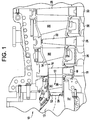
- Turbine (10) receives hot gases of combustion from an annular array of combustors (not shown), which transmit the hot gases through a transition duct (12) that leads to a combustion-receiving zone (13). The combustion gases pass through transition duct (12) into combustion receiving zone (13) and flow along an annular hot gases path (14).
- a number of turbine stages (not separated labeled) are disposed along hot gas path (14).
- Each turbine stage includes a plurality of circumferentially spaced buckets mounted on and forming part of a turbine roller and a plurality of circumferentially spaced stator vanes forming an annular array of nozzles.
- turbine (10) includes a first stage having a plurality of circumferentially spaced buckets (16) mounted on a first-stage roller wheel (18) and a plurality of circumferentially spaced-stator vanes (20).
- turbine (10) includes a second stage having a plurality of buckets (22) mounted on a roller wheel (24) and a plurality circumferentially-spaced stator vanes (26).
- turbine (10) includes a third stage having a plurality of circumferentially spaced buckets (28) mounted on a third stage roller wheel (30) and a plurality of circumferentially spaced stator vanes (32).
- the number of stages present within turbine (10) can vary.
- turbine (10) includes a plurality of spaces (34) and (36) arranged between welder wheels (18), (24) and (30).
- the compressor discharge air is located in a region (37) disposed radially inward of the first turbine stage such that air within region (37) is at a higher pressure than the pressure of the hot gases following along hot gas path (14).
- stator vanes (20) forming the first-stage nozzles are disposed between inner and outer bands (38) and (40) respectively.
- the nozzles of the first stage are formed of a plurality of nozzle segments (41), each mounting one, preferably two, stator vanes that extend between inner and outer band portions (38) and (40) in an annular array of segments.
- the exemplary embodiment of the present invention is directed to an interface provided between a static member (52) and transition duct (12). More particularly, the exemplary embodiment of the present invention is directed to a flexible seal (54) arranged between static member (52) and transition duct (12).
- transition duct (12) includes a first end portion (62) and a second end portion (63) that define an outer surface (64) and an inner surface (65).
- First end portion (62) connects to a combustion chamber portion (not shown) of turbine (10) while second end portion (63) is fluidly connected to static member (52).
- Static member (52) includes a main body portion (70) having a flange member (72).
- Flange member (72) includes a first surface (74) and a second surface (75) that define an opening (76) that leads into combustion gas receiving zone (13).
- flexible seal (54) extends about opening (76) and, when brought into contact with second end portion (63), establishes a border between compressor discharge air and combustion gases.
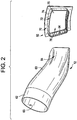
- flexible seal (54) includes a leaf spring component (91) and a seal component (93). More specifically, leaf spring component (91) includes a first leaf spring component layer (95) joined to a second leaf spring component layer (96). In the exemplary embodiment shown, first and second leaf spring component layers (95) and (96) are welded to one to the other, but could also be joined through a variety of joining techniques including both chemical and mechanical bonding techniques. In any case, first and second leaf spring component layers (95) and (96) are laminated to form leaf spring component (91).
- First leaf spring component layer (95) includes one or more laminated layers shaped (in cross-section) to match second surface (75) so as to seal any gaps between static structure (52) and transition duct (12).
- first leaf spring component layer (95) included a base section (99) and a plurality of biasing or leaf members, one of which is indicated at (100). More specifically, leaf members (100) are established by forming a series of narrow, shallow cuts (not separately labeled) in first leaf spring component layer (95). The series of narrow, shallow cuts form leaf members (100) on a first surface (not separately labeled) of first leaf spring component layer (95) and a single solid surface on an opposing surface (also not separately labeled) of first leaf spring component layer (95).
- each leaf member (100) includes a first portion (103) that extends from base section (99) to a cantilevered portion (105).
- second leaf spring component layer (96) includes a base section (110) and plurality of biasing or leaf members, one of which is indicated at (111).
- each of the plurality of leaf members (111) includes a first portion (114) that extends from base section (110) to a cantilevered portion (116).
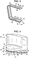
- leaf members (100) and (111) bias seal component (93) into a gap (not separately labeled) defined between transition duct (12) and static member (52).
- seal component (93) is further loaded by a pressure differential that exists between hot gases passing into turbine (10) and cooling air supplied by compressor (not shown).
- bias should be understood to include a force provided by leaf members (100) and/or (111), a force resulting from a pressure differential or combinations thereof.
- base section (99) is secured to second end portion (63) of transition duct (12) such that leaf members (100) and (111) bias braided rope (130) into contact with second surface (75) of flange member (72).
- Base section (99) is fixedly secured to second end portion (63) of transition duct (12). More specifically, base section (99) is secured to second end portion (63) by metallurgical bond such as a plurality of welds.
- metallurgical bond such as a plurality of welds.
- various other bonding techniques could be employed such as brazing.
- plurality of leaf members (100) and (111) are each separately biased towards second surface (75) of flange member (72) in order to ensure that braided rope (130) is in complete contact with static member (52). That is, by using a plurality of discreet leaf members' inconsistencies that may be present in second surface (75) accommodated.
- seal (95) is hard mounted to one of static member (52) and transition duct (12) and biased against the other of static member (52) and transition duct (12).
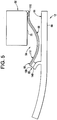
- FIG. 5 illustrates an extended member or element (140) arranged on outer surface (64) of transition duct (12).
- extended element (140) takes the form of a hook that is positioned adjacent second end portion (63) and extends circumferentially about outer surface (64).
- Flexible seal (152) is mounted to outer surface (64) of transition duct (12).
- Flexible seal (152) is a single layer leaf spring component including a base section (199) having a plurality of leaf members (200).
- Each of the plurality leaf members (200) includes a first end section (203) that extends from base section (199) to a second, cantilevered end section (205) that is provided with a seal element (210).
- Seal element (210) in the exemplary embodiment shown, is a braided rope or sealing member (230) that is positioned on the plurality of leaf members (200) adjacent cantilevered end portion (205).
- braided rope (230) is arranged in a zigzag configuration across the plurality of leaf members (200).
- the zigzag configuration allows braided rope (230) to expand and contract in response to physical changes in transition duct (12) resulting from extensions and contractions attributed to heat generated from the operation of turbine (10).
- the flexible seal constructed according to exemplary embodiments of the present invention provides a robust sealing arrangement for sealing between a static portion and a moveable portion of a turbine engine. That is, the flexible seal is designed to accommodate various inconsistencies and changes that occur between the moveable and static components of the turbine engine resulting from expansion and contractions associated with heat generated during the operation of turbine (10).
Landscapes
- Engineering & Computer Science (AREA)
- General Engineering & Computer Science (AREA)
- Mechanical Engineering (AREA)
- Chemical & Material Sciences (AREA)
- Combustion & Propulsion (AREA)
- Turbine Rotor Nozzle Sealing (AREA)
- Gasket Seals (AREA)
Claims (10)
- Eine flexible Dichtung (54) für eine Turbine (10), umfassend:eine Federkomponente (91), die einen Basisabschnitt (99, 110), der konfiguriert ist, um an einem der statischen Glieder (52) oder einem beweglichen Glied (12) der Turbinen (10) montiert zu werden, und eine Vielzahl von Vorspanngliedern (100, 111) aufweist, wobei jedes der Vielzahl von Vorspanngliedern (100, 111) einen ersten Abschnitt (103, 114), der sich vom Basisabschnitt (99, 110) aus erstreckt, und einen freitragenden Abschnitt (105, 116) aufweist; undeine Dichtungskomponente (93), die an dem freitragenden Abschnitt (105, 116) der Vielzahl von Vorspanngliedern (100, 111) vorgesehen ist, wobei die Dichtungskomponente (93) ein geflochtenes Seil (130) umfasst,dadurch gekennzeichnet, dass das geflochtene Seil (130) in einer Zick-Zack-Konfiguration angeordnet ist, wobei die Zick-Zack-Konfiguration es dem geflochtenen Seil (130) ermöglicht, sich aufgrund von Wärmeausdehnungen und Kontraktionen des beweglichen Glieds (12) zu dehnen und zusammenzuziehen, wobei das bewegliche Glied (12) ein Übergangskanal ist.
- Turbine (10), umfassend:ein statisches Glied (52);ein bewegliches Glied (12), das in Fluidverbindung mit dem statischen Glied (52) steht; undeine flexible Dichtung (54) nach Anspruch 1, wobei die Dichtungskomponente (93) in Kontakt mit dem anderen des statischen Glieds (52) und des beweglichen Glieds (12) vorgespannt ist.
- Turbine (10) nach Anspruch 2, wobei das statische Glied (52) ein Turbinenabschnitt der Turbine (10) ist, wobei
der Turbinenabschnitt eine Aufnahmezone für Verbrennungsgas (13) einschließt und der Übergangskanal (12) einen ersten Endabschnitt (62) und einen zweiten Endabschnitt (63) einschließt, der an der Aufnahmezone für Verbrennungsgas (13) des Turbinenabschnitts angeschlossen ist, wobei der Übergangskanal (12) eine Außenfläche (64) und eine Innenfläche (65) einschließt. - Turbine (10) nach Anspruch 3, wobei die flexible Dichtung (54) an der Außenfläche (64) des Übergangskanals (12) am zweiten Endabschnitt (63) montiert ist.
- Turbine (10) nach Anspruch 4, wobei der Basisabschnitt (99) an der Außenfläche (64) des Übergangskanals (12) am zweiten Endabschnitt (63) durch eine metallurgische Bindung montiert ist.
- Turbine (10) nach Anspruch 3, wobei das statische Glied (52) einen Hauptkörperabschnitt (70) und ein Flanschglied (72) einschließt, wobei das Flanschglied (72) eine Öffnung (76) definiert, die in die Aufnahmezone für Verbrennungsgas (113) des Turbinenabschnitts führt.
- Turbine (10) nach Anspruch 6, wobei die flexible Dichtung (54) an dem Flanschglied (72) montiert ist.
- Turbine (10) nach Anspruch 7, wobei der Basisabschnitt (99) der flexiblen Dichtung (54) an dem Flanschglied (72) montiert ist.
- Turbine (10) nach Anspruch 8, wobei der Übergangskanal (12) ein verlängertes Element (140) einschließt, das sich in Umfangsrichtung um die Außenfläche (64) in der Nähe des zweiten Endes (63) erstreckt, wobei die flexible Dichtung (54) an das erweiterte Element (140) angrenzt um eine Dichtung bereitzustellen.
- Turbine (10) nach Anspruch 9, wobei das verlängerte Element (140) ein Haken ist.
Applications Claiming Priority (1)
| Application Number | Priority Date | Filing Date | Title |
|---|---|---|---|
| PCT/RU2008/000110 WO2009113897A1 (en) | 2008-02-27 | 2008-02-27 | Turbine comprising a flexible seal and corresponding flexible seal for a gas turbine engine |
Publications (2)
| Publication Number | Publication Date |
|---|---|
| EP2247830A1 EP2247830A1 (de) | 2010-11-10 |
| EP2247830B1 true EP2247830B1 (de) | 2019-04-10 |
Family
ID=39967636
Family Applications (1)
| Application Number | Title | Priority Date | Filing Date |
|---|---|---|---|
| EP08873312.6A Active EP2247830B1 (de) | 2008-02-27 | 2008-02-27 | Flexible dichtung für eine turbine und zugehörige turbine |
Country Status (4)
| Country | Link |
|---|---|
| US (1) | US8322976B2 (de) |
| EP (1) | EP2247830B1 (de) |
| JP (1) | JP5302979B2 (de) |
| WO (1) | WO2009113897A1 (de) |
Cited By (1)
| Publication number | Priority date | Publication date | Assignee | Title |
|---|---|---|---|---|
| WO2024194576A1 (fr) * | 2023-03-23 | 2024-09-26 | Safran Aircraft Engines | Joint d'étanchéité pour une turbomachine d'aéronef |
Families Citing this family (14)
| Publication number | Priority date | Publication date | Assignee | Title |
|---|---|---|---|---|
| US9115585B2 (en) | 2011-06-06 | 2015-08-25 | General Electric Company | Seal assembly for gas turbine |
| US20120304657A1 (en) * | 2011-06-06 | 2012-12-06 | General Electric Company | Lock leaf hula seal |
| US9140213B2 (en) * | 2011-12-06 | 2015-09-22 | United Technologies Corporation | Leaf spring damper for a turbine engine fuel delivery system |
| US20130341426A1 (en) * | 2012-02-10 | 2013-12-26 | United Technologies Corporation | Flexible leaf spring seal for sealing an air gap between moving plates |
| US20130283817A1 (en) * | 2012-04-30 | 2013-10-31 | General Electric Company | Flexible seal for transition duct in turbine system |
| US9988155B2 (en) * | 2013-02-07 | 2018-06-05 | United Technologies Corporation | System and method for aft mount of gas turbine engine |
| US9435266B2 (en) | 2013-03-15 | 2016-09-06 | Rolls-Royce North American Technologies, Inc. | Seals for a gas turbine engine |
| US10082085B2 (en) | 2013-12-17 | 2018-09-25 | Rolls-Royce North American Technologies Inc. | Seal for gas turbine engines |
| US10502320B2 (en) * | 2014-09-02 | 2019-12-10 | Rohr, Inc. | Spring retainer seal |
| US20170051983A1 (en) * | 2015-08-18 | 2017-02-23 | Arvos Inc. | Flexible seal for a rotary regenerative preheater |
| US10689995B2 (en) * | 2016-05-27 | 2020-06-23 | General Electric Company | Side seal with reduced corner leakage |
| US11702941B2 (en) * | 2018-11-09 | 2023-07-18 | Raytheon Technologies Corporation | Airfoil with baffle having flange ring affixed to platform |
| US11286802B2 (en) | 2019-10-09 | 2022-03-29 | Rolls-Royce Corporation | Turbine shroud segment having a seal segment perimeter seal with separated buffer cavities |
| US12264630B2 (en) * | 2023-07-31 | 2025-04-01 | Rolls-Royce North American Technologies Inc. | Compliant joint for sealing interface between gas turbine engine components |
Family Cites Families (42)
| Publication number | Priority date | Publication date | Assignee | Title |
|---|---|---|---|---|
| US110549A (en) | 1870-12-27 | Improvement in cotton-presses | ||
| US227148A (en) | 1880-05-04 | T-coupling | ||
| US654257A (en) | 1898-07-23 | 1900-07-24 | Canister Mfg Company | Can-heading machine. |
| US875721A (en) | 1907-03-29 | 1908-01-07 | Nicholas H Mertes | Thill-coupling. |
| US1609952A (en) | 1923-06-30 | 1926-12-07 | Budd Edward G Mfg Co | Detachable upholstery for vehicle bodies |
| US3759038A (en) * | 1971-12-09 | 1973-09-18 | Westinghouse Electric Corp | Self aligning combustor and transition structure for a gas turbine |
| US3965066A (en) | 1974-03-15 | 1976-06-22 | General Electric Company | Combustor-turbine nozzle interconnection |
| GB2037380A (en) * | 1978-12-21 | 1980-07-09 | Rolls Royce | Seals |
| US4645217A (en) * | 1985-11-29 | 1987-02-24 | United Technologies Corporation | Finger seal assembly |
| JPS6371433U (de) * | 1986-10-29 | 1988-05-13 | ||
| US4785623A (en) | 1987-12-09 | 1988-11-22 | United Technologies Corporation | Combustor seal and support |
| JP2585751B2 (ja) * | 1988-09-30 | 1997-02-26 | 株式会社日立製作所 | ガスタービン燃焼装置 |
| US5014917A (en) * | 1989-11-27 | 1991-05-14 | The United States Of America As Represented By The Administrator Of The National Aeronautics And Space Administration | High-temperature, flexible, thermal barrier seal |
| US5127799A (en) | 1990-12-17 | 1992-07-07 | Allied-Signal Inc. | Interstage coupling seal and method of assembling a gas turbine engine |
| US5125796A (en) | 1991-05-14 | 1992-06-30 | General Electric Company | Transition piece seal spring for a gas turbine |
| US5400586A (en) | 1992-07-28 | 1995-03-28 | General Electric Co. | Self-accommodating brush seal for gas turbine combustor |
| US5265412A (en) * | 1992-07-28 | 1993-11-30 | General Electric Company | Self-accommodating brush seal for gas turbine combustor |
| US5333992A (en) | 1993-02-05 | 1994-08-02 | United Technologies Corporation | Coolable outer air seal assembly for a gas turbine engine |
| GB9304994D0 (en) * | 1993-03-11 | 1993-04-28 | Rolls Royce Plc | Improvements in or relating to gas turbine engines |
| GB9305012D0 (en) | 1993-03-11 | 1993-04-28 | Rolls Royce Plc | Sealing structures for gas turbine engines |
| US5657998A (en) * | 1994-09-19 | 1997-08-19 | General Electric Company | Gas-path leakage seal for a gas turbine |
| JPH09195799A (ja) * | 1996-01-17 | 1997-07-29 | Mitsubishi Heavy Ind Ltd | 燃焼器のスプリングシール装置 |
| US5630700A (en) * | 1996-04-26 | 1997-05-20 | General Electric Company | Floating vane turbine nozzle |
| US5915697A (en) * | 1997-09-22 | 1999-06-29 | General Electric Company | Flexible cloth seal assembly |
| JP2002071136A (ja) * | 2000-08-28 | 2002-03-08 | Hitachi Ltd | 燃焼器ライナ |
| WO2002027148A1 (en) * | 2000-09-28 | 2002-04-04 | Siemens Westinghouse Power Corporation | Flexible interlocking combustor transition seal |
| US20020121744A1 (en) * | 2001-03-05 | 2002-09-05 | General Electric Company | Low leakage flexible cloth seals for turbine combustors |
| US6547257B2 (en) * | 2001-05-04 | 2003-04-15 | General Electric Company | Combination transition piece floating cloth seal and stage 1 turbine nozzle flexible sealing element |
| US7080513B2 (en) | 2001-08-04 | 2006-07-25 | Siemens Aktiengesellschaft | Seal element for sealing a gap and combustion turbine having a seal element |
| JP3600912B2 (ja) * | 2001-09-12 | 2004-12-15 | 川崎重工業株式会社 | 燃焼器ライナのシール構造 |
| US6637752B2 (en) | 2001-12-28 | 2003-10-28 | General Electric Company | Supplemental seal for the chordal hinge seal in a gas turbine |
| US6675584B1 (en) | 2002-08-15 | 2004-01-13 | Power Systems Mfg, Llc | Coated seal article used in turbine engines |
| US6860108B2 (en) | 2003-01-22 | 2005-03-01 | Mitsubishi Heavy Industries, Ltd. | Gas turbine tail tube seal and gas turbine using the same |
| US6895757B2 (en) | 2003-02-10 | 2005-05-24 | General Electric Company | Sealing assembly for the aft end of a ceramic matrix composite liner in a gas turbine engine combustor |
| JP3795036B2 (ja) * | 2003-03-14 | 2006-07-12 | 三菱重工業株式会社 | タービン尾筒のシール構造およびシール装置 |
| JP2005337122A (ja) * | 2004-05-27 | 2005-12-08 | Ishikawajima Harima Heavy Ind Co Ltd | ガスシール装置 |
| US7007482B2 (en) | 2004-05-28 | 2006-03-07 | Power Systems Mfg., Llc | Combustion liner seal with heat transfer augmentation |
| US7052234B2 (en) * | 2004-06-23 | 2006-05-30 | General Electric Company | Turbine vane collar seal |
| GB2417528B (en) * | 2004-08-23 | 2008-08-06 | Alstom Technology Ltd | Improved rope seal for gas turbine engines |
| JP4751832B2 (ja) * | 2004-09-30 | 2011-08-17 | イーグル・エンジニアリング・エアロスペース株式会社 | シール部品 |
| US7246995B2 (en) * | 2004-12-10 | 2007-07-24 | Siemens Power Generation, Inc. | Seal usable between a transition and a turbine vane assembly in a turbine engine |
| US7524167B2 (en) * | 2006-05-04 | 2009-04-28 | Siemens Energy, Inc. | Combustor spring clip seal system |
-
2008
- 2008-02-27 WO PCT/RU2008/000110 patent/WO2009113897A1/en not_active Ceased
- 2008-02-27 EP EP08873312.6A patent/EP2247830B1/de active Active
- 2008-02-27 JP JP2010548635A patent/JP5302979B2/ja active Active
- 2008-04-07 US US12/098,860 patent/US8322976B2/en active Active
Non-Patent Citations (1)
| Title |
|---|
| None * |
Cited By (2)
| Publication number | Priority date | Publication date | Assignee | Title |
|---|---|---|---|---|
| WO2024194576A1 (fr) * | 2023-03-23 | 2024-09-26 | Safran Aircraft Engines | Joint d'étanchéité pour une turbomachine d'aéronef |
| FR3146930A1 (fr) * | 2023-03-23 | 2024-09-27 | Safran Aircraft Engines | Joint d’étanchéité pour une turbomachine d’aéronef |
Also Published As
| Publication number | Publication date |
|---|---|
| WO2009113897A1 (en) | 2009-09-17 |
| JP2011513632A (ja) | 2011-04-28 |
| JP5302979B2 (ja) | 2013-10-02 |
| US20090212504A1 (en) | 2009-08-27 |
| EP2247830A1 (de) | 2010-11-10 |
| US8322976B2 (en) | 2012-12-04 |
Similar Documents
| Publication | Publication Date | Title |
|---|---|---|
| EP2247830B1 (de) | Flexible dichtung für eine turbine und zugehörige turbine | |
| US9115585B2 (en) | Seal assembly for gas turbine | |
| JP4781017B2 (ja) | タービンベーンのカラーシール | |
| US7367567B2 (en) | Low leakage finger seal | |
| US8573603B2 (en) | Split ring seal with spring element | |
| EP2592231B1 (de) | Flexible Metalldichtung für einen Überleitkanal in einem Turbinensystem | |
| EP1795705B1 (de) | Dichtungen für Statorschaufel aus keramischem Matrix-Verbundwerkstoff | |
| EP2642078B1 (de) | System und Verfahren zur Rückführung eines durch eine Gasturbine strömenden Heißgases | |
| US9297266B2 (en) | Method of sealing combustor liner and turbine nozzle interface | |
| US8752395B2 (en) | Combustor liner support and seal assembly | |
| US20130283817A1 (en) | Flexible seal for transition duct in turbine system | |
| JP2015078687A (ja) | ガスタービンのシーリングを容易にする方法およびシステム | |
| US8888445B2 (en) | Turbomachine seal assembly | |
| US9464536B2 (en) | Sealing arrangement for a turbine system and method of sealing between two turbine components | |
| US11187152B1 (en) | Turbomachine sealing arrangement having a cooling flow director | |
| US11702991B2 (en) | Turbomachine sealing arrangement having a heat shield | |
| US20160160667A1 (en) | Discourager seal for a turbine engine | |
| US10731493B2 (en) | Gas turbine engine seal | |
| US11821365B2 (en) | Inducer seal with integrated inducer slots |
Legal Events
| Date | Code | Title | Description |
|---|---|---|---|
| PUAI | Public reference made under article 153(3) epc to a published international application that has entered the european phase |
Free format text: ORIGINAL CODE: 0009012 |
|
| 17P | Request for examination filed |
Effective date: 20100927 |
|
| AK | Designated contracting states |
Kind code of ref document: A1 Designated state(s): AT BE BG CH CY CZ DE DK EE ES FI FR GB GR HR HU IE IS IT LI LT LU LV MC MT NL NO PL PT RO SE SI SK TR |
|
| AX | Request for extension of the european patent |
Extension state: AL BA MK RS |
|
| DAX | Request for extension of the european patent (deleted) | ||
| STAA | Information on the status of an ep patent application or granted ep patent |
Free format text: STATUS: EXAMINATION IS IN PROGRESS |
|
| 17Q | First examination report despatched |
Effective date: 20161130 |
|
| GRAP | Despatch of communication of intention to grant a patent |
Free format text: ORIGINAL CODE: EPIDOSNIGR1 |
|
| STAA | Information on the status of an ep patent application or granted ep patent |
Free format text: STATUS: GRANT OF PATENT IS INTENDED |
|
| INTG | Intention to grant announced |
Effective date: 20181129 |
|
| GRAS | Grant fee paid |
Free format text: ORIGINAL CODE: EPIDOSNIGR3 |
|
| GRAA | (expected) grant |
Free format text: ORIGINAL CODE: 0009210 |
|
| STAA | Information on the status of an ep patent application or granted ep patent |
Free format text: STATUS: THE PATENT HAS BEEN GRANTED |
|
| AK | Designated contracting states |
Kind code of ref document: B1 Designated state(s): AT BE BG CH CY CZ DE DK EE ES FI FR GB GR HR HU IE IS IT LI LT LU LV MC MT NL NO PL PT RO SE SI SK TR |
|
| REG | Reference to a national code |
Ref country code: GB Ref legal event code: FG4D |
|
| REG | Reference to a national code |
Ref country code: CH Ref legal event code: EP Ref country code: AT Ref legal event code: REF Ref document number: 1118912 Country of ref document: AT Kind code of ref document: T Effective date: 20190415 |
|
| REG | Reference to a national code |
Ref country code: IE Ref legal event code: FG4D |
|
| REG | Reference to a national code |
Ref country code: DE Ref legal event code: R096 Ref document number: 602008059721 Country of ref document: DE |
|
| REG | Reference to a national code |
Ref country code: NL Ref legal event code: MP Effective date: 20190410 |
|
| REG | Reference to a national code |
Ref country code: LT Ref legal event code: MG4D |
|
| REG | Reference to a national code |
Ref country code: AT Ref legal event code: MK05 Ref document number: 1118912 Country of ref document: AT Kind code of ref document: T Effective date: 20190410 |
|
| PG25 | Lapsed in a contracting state [announced via postgrant information from national office to epo] |
Ref country code: NL Free format text: LAPSE BECAUSE OF FAILURE TO SUBMIT A TRANSLATION OF THE DESCRIPTION OR TO PAY THE FEE WITHIN THE PRESCRIBED TIME-LIMIT Effective date: 20190410 |
|
| PG25 | Lapsed in a contracting state [announced via postgrant information from national office to epo] |
Ref country code: PT Free format text: LAPSE BECAUSE OF FAILURE TO SUBMIT A TRANSLATION OF THE DESCRIPTION OR TO PAY THE FEE WITHIN THE PRESCRIBED TIME-LIMIT Effective date: 20190910 Ref country code: NO Free format text: LAPSE BECAUSE OF FAILURE TO SUBMIT A TRANSLATION OF THE DESCRIPTION OR TO PAY THE FEE WITHIN THE PRESCRIBED TIME-LIMIT Effective date: 20190710 Ref country code: HR Free format text: LAPSE BECAUSE OF FAILURE TO SUBMIT A TRANSLATION OF THE DESCRIPTION OR TO PAY THE FEE WITHIN THE PRESCRIBED TIME-LIMIT Effective date: 20190410 Ref country code: SE Free format text: LAPSE BECAUSE OF FAILURE TO SUBMIT A TRANSLATION OF THE DESCRIPTION OR TO PAY THE FEE WITHIN THE PRESCRIBED TIME-LIMIT Effective date: 20190410 Ref country code: FI Free format text: LAPSE BECAUSE OF FAILURE TO SUBMIT A TRANSLATION OF THE DESCRIPTION OR TO PAY THE FEE WITHIN THE PRESCRIBED TIME-LIMIT Effective date: 20190410 Ref country code: ES Free format text: LAPSE BECAUSE OF FAILURE TO SUBMIT A TRANSLATION OF THE DESCRIPTION OR TO PAY THE FEE WITHIN THE PRESCRIBED TIME-LIMIT Effective date: 20190410 Ref country code: LT Free format text: LAPSE BECAUSE OF FAILURE TO SUBMIT A TRANSLATION OF THE DESCRIPTION OR TO PAY THE FEE WITHIN THE PRESCRIBED TIME-LIMIT Effective date: 20190410 |
|
| PG25 | Lapsed in a contracting state [announced via postgrant information from national office to epo] |
Ref country code: BG Free format text: LAPSE BECAUSE OF FAILURE TO SUBMIT A TRANSLATION OF THE DESCRIPTION OR TO PAY THE FEE WITHIN THE PRESCRIBED TIME-LIMIT Effective date: 20190710 Ref country code: LV Free format text: LAPSE BECAUSE OF FAILURE TO SUBMIT A TRANSLATION OF THE DESCRIPTION OR TO PAY THE FEE WITHIN THE PRESCRIBED TIME-LIMIT Effective date: 20190410 Ref country code: PL Free format text: LAPSE BECAUSE OF FAILURE TO SUBMIT A TRANSLATION OF THE DESCRIPTION OR TO PAY THE FEE WITHIN THE PRESCRIBED TIME-LIMIT Effective date: 20190410 Ref country code: GR Free format text: LAPSE BECAUSE OF FAILURE TO SUBMIT A TRANSLATION OF THE DESCRIPTION OR TO PAY THE FEE WITHIN THE PRESCRIBED TIME-LIMIT Effective date: 20190711 |
|
| PG25 | Lapsed in a contracting state [announced via postgrant information from national office to epo] |
Ref country code: AT Free format text: LAPSE BECAUSE OF FAILURE TO SUBMIT A TRANSLATION OF THE DESCRIPTION OR TO PAY THE FEE WITHIN THE PRESCRIBED TIME-LIMIT Effective date: 20190410 Ref country code: IS Free format text: LAPSE BECAUSE OF FAILURE TO SUBMIT A TRANSLATION OF THE DESCRIPTION OR TO PAY THE FEE WITHIN THE PRESCRIBED TIME-LIMIT Effective date: 20190810 |
|
| REG | Reference to a national code |
Ref country code: DE Ref legal event code: R097 Ref document number: 602008059721 Country of ref document: DE |
|
| PG25 | Lapsed in a contracting state [announced via postgrant information from national office to epo] |
Ref country code: RO Free format text: LAPSE BECAUSE OF FAILURE TO SUBMIT A TRANSLATION OF THE DESCRIPTION OR TO PAY THE FEE WITHIN THE PRESCRIBED TIME-LIMIT Effective date: 20190410 Ref country code: SK Free format text: LAPSE BECAUSE OF FAILURE TO SUBMIT A TRANSLATION OF THE DESCRIPTION OR TO PAY THE FEE WITHIN THE PRESCRIBED TIME-LIMIT Effective date: 20190410 Ref country code: DK Free format text: LAPSE BECAUSE OF FAILURE TO SUBMIT A TRANSLATION OF THE DESCRIPTION OR TO PAY THE FEE WITHIN THE PRESCRIBED TIME-LIMIT Effective date: 20190410 Ref country code: EE Free format text: LAPSE BECAUSE OF FAILURE TO SUBMIT A TRANSLATION OF THE DESCRIPTION OR TO PAY THE FEE WITHIN THE PRESCRIBED TIME-LIMIT Effective date: 20190410 Ref country code: CZ Free format text: LAPSE BECAUSE OF FAILURE TO SUBMIT A TRANSLATION OF THE DESCRIPTION OR TO PAY THE FEE WITHIN THE PRESCRIBED TIME-LIMIT Effective date: 20190410 |
|
| PLBE | No opposition filed within time limit |
Free format text: ORIGINAL CODE: 0009261 |
|
| STAA | Information on the status of an ep patent application or granted ep patent |
Free format text: STATUS: NO OPPOSITION FILED WITHIN TIME LIMIT |
|
| PG25 | Lapsed in a contracting state [announced via postgrant information from national office to epo] |
Ref country code: IT Free format text: LAPSE BECAUSE OF FAILURE TO SUBMIT A TRANSLATION OF THE DESCRIPTION OR TO PAY THE FEE WITHIN THE PRESCRIBED TIME-LIMIT Effective date: 20190410 |
|
| 26N | No opposition filed |
Effective date: 20200113 |
|
| PG25 | Lapsed in a contracting state [announced via postgrant information from national office to epo] |
Ref country code: TR Free format text: LAPSE BECAUSE OF FAILURE TO SUBMIT A TRANSLATION OF THE DESCRIPTION OR TO PAY THE FEE WITHIN THE PRESCRIBED TIME-LIMIT Effective date: 20190410 |
|
| PG25 | Lapsed in a contracting state [announced via postgrant information from national office to epo] |
Ref country code: SI Free format text: LAPSE BECAUSE OF FAILURE TO SUBMIT A TRANSLATION OF THE DESCRIPTION OR TO PAY THE FEE WITHIN THE PRESCRIBED TIME-LIMIT Effective date: 20190410 |
|
| REG | Reference to a national code |
Ref country code: CH Ref legal event code: PL |
|
| GBPC | Gb: european patent ceased through non-payment of renewal fee |
Effective date: 20200227 |
|
| REG | Reference to a national code |
Ref country code: BE Ref legal event code: MM Effective date: 20200229 |
|
| PG25 | Lapsed in a contracting state [announced via postgrant information from national office to epo] |
Ref country code: MC Free format text: LAPSE BECAUSE OF FAILURE TO SUBMIT A TRANSLATION OF THE DESCRIPTION OR TO PAY THE FEE WITHIN THE PRESCRIBED TIME-LIMIT Effective date: 20190410 Ref country code: LU Free format text: LAPSE BECAUSE OF NON-PAYMENT OF DUE FEES Effective date: 20200227 |
|
| PG25 | Lapsed in a contracting state [announced via postgrant information from national office to epo] |
Ref country code: LI Free format text: LAPSE BECAUSE OF NON-PAYMENT OF DUE FEES Effective date: 20200229 Ref country code: CH Free format text: LAPSE BECAUSE OF NON-PAYMENT OF DUE FEES Effective date: 20200229 |
|
| PG25 | Lapsed in a contracting state [announced via postgrant information from national office to epo] |
Ref country code: FR Free format text: LAPSE BECAUSE OF NON-PAYMENT OF DUE FEES Effective date: 20200229 Ref country code: IE Free format text: LAPSE BECAUSE OF NON-PAYMENT OF DUE FEES Effective date: 20200227 Ref country code: GB Free format text: LAPSE BECAUSE OF NON-PAYMENT OF DUE FEES Effective date: 20200227 |
|
| PG25 | Lapsed in a contracting state [announced via postgrant information from national office to epo] |
Ref country code: BE Free format text: LAPSE BECAUSE OF NON-PAYMENT OF DUE FEES Effective date: 20200229 |
|
| PG25 | Lapsed in a contracting state [announced via postgrant information from national office to epo] |
Ref country code: MT Free format text: LAPSE BECAUSE OF FAILURE TO SUBMIT A TRANSLATION OF THE DESCRIPTION OR TO PAY THE FEE WITHIN THE PRESCRIBED TIME-LIMIT Effective date: 20190410 Ref country code: CY Free format text: LAPSE BECAUSE OF FAILURE TO SUBMIT A TRANSLATION OF THE DESCRIPTION OR TO PAY THE FEE WITHIN THE PRESCRIBED TIME-LIMIT Effective date: 20190410 |
|
| REG | Reference to a national code |
Ref country code: DE Ref legal event code: R082 Ref document number: 602008059721 Country of ref document: DE Ref country code: DE Ref legal event code: R081 Ref document number: 602008059721 Country of ref document: DE Owner name: GENERAL ELECTRIC TECHNOLOGY GMBH, CH Free format text: FORMER OWNER: GENERAL ELECTRIC COMPANY, SCHENECTADY, NY, US |
|
| PGFP | Annual fee paid to national office [announced via postgrant information from national office to epo] |
Ref country code: DE Payment date: 20250122 Year of fee payment: 18 |