EP2247464B1 - Lenkungsanordnung für ein fahrzeug mit einer drehbaren lenkhandhabe - Google Patents
Lenkungsanordnung für ein fahrzeug mit einer drehbaren lenkhandhabe Download PDFInfo
- Publication number
- EP2247464B1 EP2247464B1 EP09716162A EP09716162A EP2247464B1 EP 2247464 B1 EP2247464 B1 EP 2247464B1 EP 09716162 A EP09716162 A EP 09716162A EP 09716162 A EP09716162 A EP 09716162A EP 2247464 B1 EP2247464 B1 EP 2247464B1
- Authority
- EP
- European Patent Office
- Prior art keywords
- steering
- hammer
- pinging
- steering arrangement
- rocker bar
- Prior art date
- Legal status (The legal status is an assumption and is not a legal conclusion. Google has not performed a legal analysis and makes no representation as to the accuracy of the status listed.)
- Not-in-force
Links
- 241000446313 Lamella Species 0.000 claims description 11
- 125000006850 spacer group Chemical group 0.000 claims description 8
- 230000033001 locomotion Effects 0.000 description 15
- 238000012546 transfer Methods 0.000 description 5
- 230000005540 biological transmission Effects 0.000 description 3
- 238000004891 communication Methods 0.000 description 3
- 239000000463 material Substances 0.000 description 3
- 239000002184 metal Substances 0.000 description 3
- 230000003534 oscillatory effect Effects 0.000 description 3
- 238000002485 combustion reaction Methods 0.000 description 2
- 230000002349 favourable effect Effects 0.000 description 2
- 230000005484 gravity Effects 0.000 description 2
- 230000010355 oscillation Effects 0.000 description 2
- 238000010079 rubber tapping Methods 0.000 description 2
- 230000008054 signal transmission Effects 0.000 description 2
- 238000013459 approach Methods 0.000 description 1
- 230000000712 assembly Effects 0.000 description 1
- 238000000429 assembly Methods 0.000 description 1
- 238000010009 beating Methods 0.000 description 1
- 238000005253 cladding Methods 0.000 description 1
- 238000010276 construction Methods 0.000 description 1
- 238000013461 design Methods 0.000 description 1
- 238000001514 detection method Methods 0.000 description 1
- 238000010586 diagram Methods 0.000 description 1
- 238000006073 displacement reaction Methods 0.000 description 1
- 230000000694 effects Effects 0.000 description 1
- 238000004146 energy storage Methods 0.000 description 1
- 230000005284 excitation Effects 0.000 description 1
- 239000002828 fuel tank Substances 0.000 description 1
- 231100001261 hazardous Toxicity 0.000 description 1
- 238000005286 illumination Methods 0.000 description 1
- 230000007257 malfunction Effects 0.000 description 1
- 238000012544 monitoring process Methods 0.000 description 1
- 239000006223 plastic coating Substances 0.000 description 1
- 230000000717 retained effect Effects 0.000 description 1
- 230000035939 shock Effects 0.000 description 1
- 238000005476 soldering Methods 0.000 description 1
- 239000007787 solid Substances 0.000 description 1
- 239000000725 suspension Substances 0.000 description 1
- 230000000007 visual effect Effects 0.000 description 1
- 238000003466 welding Methods 0.000 description 1
Images


Classifications
-
- B—PERFORMING OPERATIONS; TRANSPORTING
- B62—LAND VEHICLES FOR TRAVELLING OTHERWISE THAN ON RAILS
- B62D—MOTOR VEHICLES; TRAILERS
- B62D15/00—Steering not otherwise provided for
- B62D15/02—Steering position indicators ; Steering position determination; Steering aids
- B62D15/029—Steering assistants using warnings or proposing actions to the driver without influencing the steering system
-
- Y—GENERAL TAGGING OF NEW TECHNOLOGICAL DEVELOPMENTS; GENERAL TAGGING OF CROSS-SECTIONAL TECHNOLOGIES SPANNING OVER SEVERAL SECTIONS OF THE IPC; TECHNICAL SUBJECTS COVERED BY FORMER USPC CROSS-REFERENCE ART COLLECTIONS [XRACs] AND DIGESTS
- Y10—TECHNICAL SUBJECTS COVERED BY FORMER USPC
- Y10T—TECHNICAL SUBJECTS COVERED BY FORMER US CLASSIFICATION
- Y10T74/00—Machine element or mechanism
- Y10T74/20—Control lever and linkage systems
- Y10T74/20576—Elements
- Y10T74/20732—Handles
- Y10T74/20834—Hand wheels
Definitions
- the present invention relates to a steering arrangement for a vehicle having a rotatable steering handle, in particular a steering wheel, and a rotatably connected thereto steering spindle and at least one generating device for at least one mechanical vibration, in particular a haptic signal, wherein the steering assembly has at least one swing arm and the swing arm Knocking hammer is held and the swing arm for the deflection of the knocking hammer is in communication with the generating means, wherein the swing arm is fixed to a component of the steering assembly in a fixing region and the knocking hammer is held deflectable on the swing arm relative to the fixing and the knocking hammer with a component of the steering assembly in Contact is bringable.
- the basic idea of the steering arrangements known per se with a generating device for at least one haptic signal is to transmit a signal, in particular a warning signal, to the driver of the vehicle via the sense of touch present in his hands.
- a signal in particular a warning signal
- the generator device directly into the steering handle or the steering wheel. After a steering wheel but must always be hung rotatable, here are problems with the signal transmission to the steering wheel. Although this can be solved by slip rings or twisted wires or the like., But is always relatively expensive.
- a solution with a positive transfer of a haptic signal to a steering column of a vehicle is in the DE 10 306 100 A1 proposed.
- a haptic perceptible, directionally selective and impulsively applied torque is transmitted to the steering column and thus to the steering wheel via the engagement of different gears in one another as a function of a detected by a detection system directional deviation.
- arrangements shown are technically relatively expensive.
- a swing arm knock assembly for a vehicle pedal is known.
- the swing arm is axially displaceably mounted in a bobbin.
- a generator with internal knocking hammer is known, which is arranged on a lamella.
- the object of the invention is to make an alternative solution proposal, as with a simple construction as possible a mechanical vibration or a haptic signal can be transmitted in a generic steering arrangement on a steering handle or a steering wheel.
- the generator device acts on the swinging arm between the fixing area and the knocking hammer.
- a swing arm which is fixedly fixed on the one hand with its fixing portion on a component of the steering assembly and on the other hand holding a knock hammer, which can be deflected via the swing arm relative to the fixing and, preferably together with the swing arm or a part of the swing arm, is displaceable in a swinging motion.
- the generating device is provided, which is in communication with the oscillating arm. Due to the mechanical vibration of the knocking hammer can be brought into contact with a component of the steering assembly. In this way it can be achieved that upon actuation of the generator device, the knocking hammer is set in vibration against a component of the steering arrangement.
- This vibration generated on the component of the steering arrangement can then be transmitted, if appropriate via various other components of the steering arrangement, to the steering spindle and thus to the steering handle or the steering wheel, so that upon actuation of the generator device a haptic, that is perceived by the driver's hand on the steering handle signal is generated.
- the mechanical vibration generated in the passenger compartment of the vehicle can be audible. In this sense, thus a haptic and / or acoustic signal is generated.
- the steering arrangement thus has a kind of bell, which can optionally produce both haptic, so palpable by hand, as well as acoustic, ie audible signals.
- the swinging arm advantageously has at least one louver, which can be set into mechanical vibration by means of the generating device, on which the knocking hammer can be held directly or indirectly.
- the lamella is the movable or elastically deformable part.
- the swing arm may consist entirely of such an elastic or vibratable slat. But it is also possible that the swing arm has substantially rigid parts per se, which are in communication with the lamella. Alternatively, it is also conceivable to form the entire swing arm substantially rigid and to fix it via a joint on the component of the steering arrangement, in which case a spring should be provided which sets the joint and thus the swing arm in bias. Overall, the knocking hammer and / or the swing arm can thus be made in one or more parts.
- the knocking hammer in its rest position, in which the generating device is switched off, abut against the component of the steering device with which it can be brought into contact.
- the knocking hammer in said rest position of the component of the steering assembly, with which it is brought into contact is spaced.
- the knocking hammer is spaced from the fixing area arranged on the swing arm. It is particularly preferred if the fixing region forms the one end of the swing arm and is arranged at the opposite end of the swing arm or the blade of the knocking hammer.
- the generator device it is first of all important that it is in contact with the oscillating arm so that it can vibrate it.
- the generating device acts on the swinging arm between the fixing region and the knocking hammer, preferably in the region of the lamella. It is again favorable, if the generator device, preferably exclusively, by the swing arm or the possibly present lamella is supported. It should be understood that, preferably exclusively, the swing arm holds the generator in position against gravity. It is irrelevant whether the generator device is also in contact with connecting cables or the like.
- the swing arm can in principle be fixed to the same component of the steering arrangement, with which the knocking hammer, in particular during knocking, can be brought into contact. But it is also conceivable that the swing arm is fixed to a first component of the steering assembly and the knocking hammer is engageable with another component of the steering assembly in contact and tapping against this.
- generator means vibrators or other producers of mechanical vibrations or knock signals in question.
- This can z.
- Such generating devices for the oscillations are known per se in the prior art and are explained here by way of example only in various embodiments.
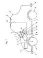
- FIG. 1 schematically shown variant of the swing arm 16 is fixed in its fixing region 11 on the shell unit 6. Between the fixing region 11 and the knocking hammer 23, the swing arm 16 carries the generating device 5, via which it can be set in vibration, whereby the knocking hammer 23 knocks against the shell unit 6.
- the generator device 5 is connected to the control device 15 in connection.
- the control device 15 receives different state parameters of the vehicle 2 via corresponding signal lines 21 in order to monitor them and to generate a signal for triggering the generator device 5 in the event of deviations from predetermined desired values or setpoint ranges.
- sensors 19 for determining the distance and / or the relative speed of before or behind the vehicle 2 are other vehicles or obstacles.
- the in Fig. 1 Vehicle 2 also has a position determination sensor 20. This can be a known GPS (Global Positioning System) antenna of a navigation system.
- the control device 15 also receives state parameters of the internal combustion engine 18 via the corresponding signal line 21.
- the sensors shown are only examples. In principle, it is conceivable to combine any state-of-the-art monitoring of state parameters of the vehicle 2 in one embodiment according to the invention with a steering arrangement.
- the respective measured parameters are conveniently compared with setpoints or setpoint ranges.
- a deviation of the measured parameters from the desired values or desired value ranges can then be evaluated by the control device 15 in such a way that the generator device 5 receives a drive signal via the signal line 21, whereupon it vibrates the oscillating arm 16 and the tapping hammer 23 generates a haptic and / or acoustic signal signal generated on the jacket unit 6, which is transmitted via the steering shaft 4 to the steering wheel 3 and / or in the passenger compartment of the vehicle 2.
- engine parameters such as engine speed, oil pressure, temperature, various ignition parameters and the like can be monitored and evaluated in order to generate a haptic and / or acoustic signal in the case of malfunctions or other deviations from nominal values.
- This signal can also be used to direct the driver's attention to a visual display.
- vehicle parameters such as tire pressure, fuel tank level, closed state of the doors and flaps of the vehicle, functioning of the illumination of the vehicle, etc.
- signals are generated in conjunction with a navigation system known per se when the vehicle leaves the predetermined path.
- a navigation system known per se when the vehicle leaves the predetermined path.
- signals can also be prevented, for example, by falling asleep the driver of the vehicle or the road departs by corresponding haptic and / or acoustic signals are generated when the vehicle 2 departs from the track. All these are, as mentioned, but only examples.
- the generator device 5 is suitable for generating, preferably in response to a control by a control device 15, at least two, preferably several, different signals and oscillations different from the inactive state of the generator device 5.
- the different signals differ from each other in their amplitude and / or frequency and / or duration and / or direction.
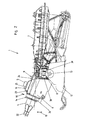
- Fig. 2 shows now in a first specific embodiment, a steering arrangement according to the invention, but only the relevant for this embodiment upper portion of the steering assembly is shown.
- the steering assembly 1 or steering column comprises a steering shaft 4, of which a portion adjacent to a connecting piece 22 for a steering wheel 3 or the like is rotatably mounted in a jacket unit 6.
- the jacket unit 6 is carried by a mountable on the chassis of a motor vehicle support unit 7. In the open state of a locking device 8, the jacket unit 6 can be adjusted relative to the support unit 7, in the embodiment shown in an adjustment direction 10th
- the locking device 8 may also be designed so that in addition to or alternatively to the direction of movement 10 and a second adjustment 9, in which the steering column in the axial direction of the steering shaft 4 adjustable is, is possible. Whether both an adjustability in the axial direction 9 and in inclination or height direction 10 is possible, is not essential to the invention.
- the locking device 8 is opened and closed by means of the manual control lever 12. This is fixedly connected to the clamping bolt 13 for this purpose. By pivoting the actuating lever 12 about the longitudinal axis of the clamping bolt 13, the locking device 8 is moved between the open and the closed state. This is known per se.
- Fig. 2 shows the position of the manual control lever 12 in the closed position of the locking device 8 in which the steering shaft 4 is fixed in position.
- the locking device 8 acts in the illustrated embodiment form-fitting manner via the meshing teeth 39.
- a positive acting locking device 8 as shown here, also frictionally acting locking devices 8 with and without lamellae, as are known in the prior art, with an inventive Swing arm 16 are equipped.
- the manner of determining the jacket unit 6 relative to the support unit 7 in the closed state of the locking device 8 and operated by pivoting of the manual control lever 12 mechanism for opening and closing the locking device 8 is not the subject of the present invention.
- the swinging arm 16 which in the example shown here carries the knocking hammer 23 at its end on the steering wheel side, is fixed to the shell unit 6 at its opposite end in the fixing region 11 by a screw 24, a rivet or the like.
- fixation can of course also a welded joint, a soldering or otherwise every other known type of connection of two components in the fixing area 11 may be provided.
- the knocking hammer 23 can be brought into contact with the same component of the steering arrangement 1, namely with the jacket unit 6, to which the swinging arm 16 is also fixed. In the rest position shown here is in this embodiment, the knocking hammer 23 on the component of the steering assembly, with which it is brought into contact - here the shell unit 6 - to.
- the oscillating arm 16 and thus also the knocking hammer 23 are set in a swinging motion whereby the knocking hammer 23 knocks against the casing unit 6 in response to the signal generated by the generating device 5.
- the swing arm 16 is substantially over its entire length from the elastic or oscillatory blade 25. Dies kann z.
- the generator 5 is supported by this fin 25.
- the knocking hammer 23 is integrally formed here on the swing arm 16 or the lamella 25. But it can of course also be attached to swing arm 16 in any other known manner.
- the shell unit 6 assumes, as is known, the supporting function for the steering shaft 4, since the latter is mounted on the arranged in the shell unit 6 and in the bearing bush 26 bearing 14.
- the steering shaft 4 is supported in a mounting position of the steering assembly in the vehicle of the shell unit 6, the steering shaft 6 is thus conveniently held by the shell unit 6 against gravity in the vehicle.
- the jacket unit 6 at least partially encloses a cavity in the form of a tunnel or tube and the steering spindle 4 is guided through this cavity.
- At least one, preferably at least two, of the abovementioned bearings 14 can be arranged in or on the sheath unit 6.
- the jacket unit 6 in this embodiment it is also used as a transmission device for transmitting the knocking signal of the knocking hammer 23.
- the jacket unit 6 advantageously assumes the function of a resonant box, via the haptic, so palpable on the sense of touch, and / or audible, ie audible, signals on the steering shaft 4 and thus also on the steering wheel 3 or a differently shaped steering handle or in the interior of the passenger compartment of the vehicle 2 can be transmitted.
- the jacket unit 6 forming the resonance box has a resonance frequency which coincides with a frequency of the knocking signal generated by the knocking hammer 23 or at least as close to the frequency of the signal that the cladding unit 6 can be resonated.
- the swing arm 16 is disposed in the front area close to the steering wheel on top of the jacket unit 6. Of course, this does not have to be this way.
- the swing arm 6 can also be arranged in the middle or in the rear area of the shell unit 6 facing away from the steering wheel 3.
- the arrangement of the swing arm 16, based on the operating position shown, below or laterally on or in the shell unit 6 possible.
- the knocking hammer 23 can knock on the support member 7.
- the knocking hammer 23 can be brought directly into contact with the steering spindle 4.
- the knocking signal is thus introduced directly into the steering shaft 4.
- the swing arm 16 is fixed with its fixing portion 11 on the shell unit 6.
- Other mounting options are conceivable.
- the attachment of the swing arm 16 to a non-rotating part of the steering assembly 1, since then not shown here supply cable for driving the generator means 5 are not subjected to a rotational movement.
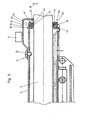
- Fig. 4 was also the fixation of the swing arm 16 retained on the shell unit 6.
- the knocking hammer 23 can be brought into contact with the bearing bush 26 or knocks on the generating device 5 during operation thereof.
- the bearing bush 26 is the part of the shell unit 6, which carries the bearing 14.
- the bearing bush 26 may be formed integrally with the remaining shell unit 6. Alternatively, it is also possible to weld the bearing bush 26 to the remaining jacket unit 6.
- connections such as screw, rivet, joint connections, caulking with one another, hammering or a connection via tabs and the like. Conceivable.
- connection between the bearing bush 26 and shell unit 6 should be favorably designed so that the vibrations generated by the knocking hammer 23 are transmitted to the shell unit 6 in order to respect the above.
- Fig. 2 to be able to achieve the discussed resonance box effect.
- This then acts in addition to the direct transfer
- Traced here are, as in all other embodiments, the vibration directions 46 in which the knocking hammer 23 oscillates when the generator means 5 is put into operation.
- Fig. 3 is in Fig. 4 to see due to the selected sectional view of the realized in this embodiment structure of the bearing 14.
- This first of all has a bearing outer ring 45, which is preferably arranged non-rotatably on the bearing bush 26 and in which the balls 43 run. These are supported inwardly against the bearing inner ring 44, which rotates relative to the bearing outer ring 45 when rotating the steering shaft 4 together with the steering shaft 4.
- the bearing inner ring 44 is held here for example by the cone ring 42 on the steering shaft 4.
- the non-positively or positively clamped on the steering shaft 4 retaining ring 41 supports the cone ring 42 in the axial direction of the steering shaft 4 and thereby prevents the thus constructed bearing 14 in the axial direction of the steering shaft 4 is moved apart.
- a large part of the knock signal is thus introduced directly from the bearing bush 26 via the thus constructed bearing 14 in the steering shaft 4.
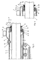
- FIG. 5 likewise embodiment shown in a sectional illustration differs from the gem.
- Fig. 4 through the arranged between the cone ring 42 and the retaining ring 41 spacer ring 40 to which the knocking hammer 23 strikes.
- the spacer ring 40 rotates together with the bearing inner ring 44, the cone ring 42 and the retaining ring 41 with the steering shaft 4.
- the retaining ring 41 is also used in this embodiment, the bearing thus constructed in the axial direction of the steering shaft 4 against the held on the bearing bush 26 Support bearing outer ring 45.
- Fig. 6 shows one opposite Fig. 5 slightly modified version.
- the cone ring 42 is integrated directly into the spacer ring 40 '.
- the other function corresponds to the according to Fig. 5 ,
- the spacer ring 40 'thus formed can, for. B. be made in one piece as a sheet metal part.
- the knocking hammer 23 beats on rotatable relative to the knocking hammer 23 parts such as the steering shaft 4, it can be provided that the knocking hammer 23 is formed as a rotatable element, such as a roller, or has such a rotatable element.
- the axis of rotation of this rotatable element or the roller should then advantageously be aligned or alignable parallel to the axis of rotation of the steering spindle, so that the knocking hammer 23 does not inhibit the rotational movement of the steering shaft 4.
- Fig. 7 shows in an external view analogous to Fig. 2 a variant in which instead of cone ring 42 and spacer 40, the bearing inner ring 44 is extended so far that the knocking hammer 23 can beat on the bearing inner ring 44. About corresponding, not shown in detail bulges ensures that the balls 43 are held in position. An axial displacement of the entire bearing inner ring 44 is again avoided by the non-positively or positively acting on the steering shaft 4 retaining ring 41.
- the signal generated by the knocking hammer 23 is transmitted, on the one hand, directly to the steering spindle 4 via the components arranged therebetween.
- the bearing 14 to the shell unit 6 but this also be set in vibration, which, as explained above, can also be used as a resonance box.
- the swing arm 16 can of course be fixed to other components of the steering assembly or the knocking hammer 23 can be brought into contact with other components of the steering assembly 1 in contact.
- the support member 7 or the locking device 8 may be provided as a counterpart for the knocking hammer 23 or as a mounting option for the swing arm 16.
- the embodiments of the oscillating arm 16, the fin 25 and in particular also the shape and choice of material of the rapier hammer 23 have an influence on how the knocking signal is perceived haptically and / or acoustically.
- the knocking hammer 23 in particular the pitch, but also the strength of the signal, can be co-controlled via the choice of material. So it is z. B. possible to form the knocking hammer 23 as a metal head or him z. B. by plastic coating or the like. To damp or equal to choose another or softer material for the knocking hammer 23.
- suitable measures prevents the knocking hammer 23 due to shock or vibration accidentally against a component of the steering assembly beats, if this is not desired.
- This can be achieved, for example, in that the knocking hammer 23 in its rest position is so far away from the part against which it is intended to knock that unwanted knocking can not occur due to vibrations or vibrations.
- An alternative measure would also be to clamp the knocking hammer 23 in its rest position firmly, and only to release it when it should, tapped by the generator means 5, knock.
- Fig. 8 shows a variant in which a piezoelectric oscillator 27 is provided as a source. By appropriate excitation this puts the hammer piece 31 inTrahub- or oscillatory movements 33, which in turn suggests the anvil 32, via which the signal thus generated is forwarded to the swing arm 16, not shown here.
- the hammer piece 31 can be fixed to the piezoelectric oscillator 27.
- the solid and broken dashed lines show as well as in the embodiment according to Fig.
- Fig. 9 shows a variant of a generating device 5 in which two additional masses 34 are arranged on the piezoelectric oscillator 27, which are mixed together with the piezoelectric oscillator 27 in a swinging motion 33 and thus amplify the signal.
- Fig. 10 shows an example with a preferably electric motor 28. This generates a rotational movement 35 of the eccentric 30. Due to its mass or imbalance generated the eccentric 30 while a mechanical vibration, which is transmitted via the motor 28 and its housing on.
- Fig. 9 shows a variant of a generating device 5 in which two additional masses 34 are arranged on the piezoelectric oscillator 27, which are mixed together with the piezoelectric oscillator 27 in a swinging motion 33 and thus amplify the signal.
- FIG. 11 shows a magnetic coil assembly 29 for a generator means 5.
- a magnetizable core coil 37 and a magnetizable plunger coil 38 On the magnetic core forming pole piece 36 sit a magnetizable core coil 37 and a magnetizable plunger coil 38.
- One of the coils is fixed to the pole piece, the other is movably mounted in the direction of the oscillatory motion 33.
- the movable coil is set in a one-time movement or in a swinging movement 33, whereby the anvil 32 is acted upon in accordance with blows or vibrated.
- the haptic signal is transmitted via the anvil 32 on.
- Swing arm to operate with a generator device 5 according to the known bell principle.
- Such a generator device 5 has at least one magnetic coil and at least one break contact, wherein the magnetic coil attracts or repels the elastically deflectable swing arm 16 until the swing arm 16 or a component attached thereto contacts the breaker contact and switches off the magnet coil, whereby the swing arm and thus also the knocking hammer is set in vibration.
- the invention has been shown with reference to a steering assembly 1 for ground-based vehicles such as cars and trucks.
- steering arrangements according to the invention can also be used for motorcycles such as motorcycles, mopeds and the like.
- the invention is not necessarily limited to steering arrangements for ground vehicles. In principle, it is also possible to use appropriate steering arrangements for aircraft, boats or ships, to mention only a few examples.
Landscapes
- Engineering & Computer Science (AREA)
- Chemical & Material Sciences (AREA)
- Combustion & Propulsion (AREA)
- Transportation (AREA)
- Mechanical Engineering (AREA)
- Steering Controls (AREA)
- Apparatuses For Generation Of Mechanical Vibrations (AREA)
- Steering Devices For Bicycles And Motorcycles (AREA)
Priority Applications (1)
| Application Number | Priority Date | Filing Date | Title |
|---|---|---|---|
| PL09716162T PL2247464T3 (pl) | 2008-02-28 | 2009-02-19 | Układ kierowniczy do pojazdu z obrotowym uchwytem kierowniczym |
Applications Claiming Priority (2)
| Application Number | Priority Date | Filing Date | Title |
|---|---|---|---|
| DE102008011621A DE102008011621B3 (de) | 2008-02-28 | 2008-02-28 | Lenkungsanordnung für ein Fahrzeug |
| PCT/AT2009/000063 WO2009105799A1 (de) | 2008-02-28 | 2009-02-19 | Lenkungsanordnung für ein fahrzeug mit einer drehbaren lenkhandhabe |
Publications (2)
| Publication Number | Publication Date |
|---|---|
| EP2247464A1 EP2247464A1 (de) | 2010-11-10 |
| EP2247464B1 true EP2247464B1 (de) | 2011-11-23 |
Family
ID=40542643
Family Applications (1)
| Application Number | Title | Priority Date | Filing Date |
|---|---|---|---|
| EP09716162A Not-in-force EP2247464B1 (de) | 2008-02-28 | 2009-02-19 | Lenkungsanordnung für ein fahrzeug mit einer drehbaren lenkhandhabe |
Country Status (6)
| Country | Link |
|---|---|
| US (1) | US8613237B2 (pl) |
| EP (1) | EP2247464B1 (pl) |
| AT (1) | ATE534545T1 (pl) |
| DE (1) | DE102008011621B3 (pl) |
| PL (1) | PL2247464T3 (pl) |
| WO (1) | WO2009105799A1 (pl) |
Families Citing this family (1)
| Publication number | Priority date | Publication date | Assignee | Title |
|---|---|---|---|---|
| JP5428582B2 (ja) * | 2009-06-30 | 2014-02-26 | 日本精工株式会社 | ステアリング装置 |
Citations (1)
| Publication number | Priority date | Publication date | Assignee | Title |
|---|---|---|---|---|
| WO2009092527A1 (de) * | 2008-01-23 | 2009-07-30 | Thyssenkrupp Presta Aktiengesellschaft | Lenkungsanordnung für ein fahrzeug mit drehbarer lenkhandhabe |
Family Cites Families (9)
| Publication number | Priority date | Publication date | Assignee | Title |
|---|---|---|---|---|
| JPS5766027A (en) * | 1980-10-06 | 1982-04-22 | Nissan Motor Co Ltd | Alarming device for vehicle |
| DE59705444D1 (de) * | 1996-06-27 | 2002-01-03 | Styner & Bienz Ag | Lagerungskasten für eine Lenkwelle eines Fahrzeuges und Verfahren zur Herstellung desselben |
| US6097286A (en) * | 1997-09-30 | 2000-08-01 | Reliance Electric Technologies, Llc | Steer by wire system with feedback |
| US7165786B1 (en) * | 1998-12-21 | 2007-01-23 | Douglas Autotech Corporation | Non-newtonian flow fluid-locking mechanism for vehicles |
| JP2004512206A (ja) * | 2000-05-31 | 2004-04-22 | ダグラス オートテック コーポレィション | アラーム機構 |
| DE20216068U1 (de) * | 2002-10-18 | 2003-03-06 | TRW Automotive Safety Systems GmbH, 63743 Aschaffenburg | Fahrzeuglenkvorrichtung und Sicherheitssystem |
| DE10306100C5 (de) * | 2003-02-14 | 2012-11-29 | Audi Ag | Kraftfahrzeug mit einem Lenksystem umfassend eine mechanische Lenksäule samt Lenkrad sowie einem System zur Erfassung einer Abweichung der Fahrspur des Kraftfahrzeugs von einer ausgezeichneten Fahrspur der Fahrbahn oder zur Erfassung einer Belegung einer Nachbarspur |
| DE102004062820A1 (de) | 2004-12-27 | 2006-07-06 | Robert Bosch Gmbh | Fahrzustandsüberwachungseinrichtung für ein Kraftfahrzeug |
| EP1777094B1 (en) * | 2005-10-19 | 2008-03-26 | C.R.F. Società Consortile per Azioni | Motor vehicle signalling system incorporating a haptic accelerator pedal |
-
2008
- 2008-02-28 DE DE102008011621A patent/DE102008011621B3/de not_active Expired - Fee Related
-
2009
- 2009-02-19 PL PL09716162T patent/PL2247464T3/pl unknown
- 2009-02-19 WO PCT/AT2009/000063 patent/WO2009105799A1/de not_active Ceased
- 2009-02-19 EP EP09716162A patent/EP2247464B1/de not_active Not-in-force
- 2009-02-19 AT AT09716162T patent/ATE534545T1/de active
-
2010
- 2010-08-23 US US12/861,268 patent/US8613237B2/en not_active Expired - Fee Related
Patent Citations (1)
| Publication number | Priority date | Publication date | Assignee | Title |
|---|---|---|---|---|
| WO2009092527A1 (de) * | 2008-01-23 | 2009-07-30 | Thyssenkrupp Presta Aktiengesellschaft | Lenkungsanordnung für ein fahrzeug mit drehbarer lenkhandhabe |
Also Published As
| Publication number | Publication date |
|---|---|
| US8613237B2 (en) | 2013-12-24 |
| US20100319481A1 (en) | 2010-12-23 |
| EP2247464A1 (de) | 2010-11-10 |
| WO2009105799A1 (de) | 2009-09-03 |
| ATE534545T1 (de) | 2011-12-15 |
| DE102008011621B3 (de) | 2009-08-13 |
| PL2247464T3 (pl) | 2012-04-30 |
Similar Documents
| Publication | Publication Date | Title |
|---|---|---|
| EP0413168B1 (de) | Nassrasierapparat | |
| DE69820920T2 (de) | Abgestimmter Schwingungsdämpfer mit doppelten Biegeelementen | |
| DE10300020B4 (de) | Vorrichtung zum Überwachen einer Drehung eines Objekts um eine Achse | |
| DE4036451A1 (de) | Motorbetriebener, einschwenkbarer aussenspiegel fuer fahrzeuge | |
| DE102008035989A1 (de) | Lenkvorrichtung mit einstückiger Lenkwelle und Drehmomentsensor sowie Fahrzeug mit einer derartigen Lenkvorrichtung | |
| EP3390158B1 (de) | Kraftfahrzeug-bedienvorrichtung mit einfahrbarem berührungsbildschirm | |
| DE69801965T2 (de) | Elektrische Servolenkung | |
| DE112006000764B4 (de) | Anzeigevorrichtung | |
| EP2909831B1 (de) | Ultraschallsensorvorrichtung mit einer versteifungseinheit, anordnung, kraftfahrzeug und verfahren zum herstellen einer anordnung | |
| DE102007024140A1 (de) | Vibratorbaugruppe für ein Kraftfahrzeug | |
| EP2760704B1 (de) | Lautsprechersystem für ein kraftfahrzeug | |
| DE102004019066B3 (de) | Steer-by-Wire-Lenkradeinheit mit integriertem Airbagmodul | |
| EP2649709B1 (de) | Handmomentensteller | |
| EP2247490B1 (de) | Lenkungsanordnung für ein fahrzeug mit drehbarer lenkhandhabe | |
| EP2247464B1 (de) | Lenkungsanordnung für ein fahrzeug mit einer drehbaren lenkhandhabe | |
| DE202009011844U1 (de) | Elektromotorischer Scheibenwischerantrieb | |
| DE20101014U1 (de) | Warnvorrichtung in einem bodengebundenen Fahrzeug | |
| DE102004030935B3 (de) | Vorrichtung zur Schwingungsdämpfung in einem Kraftfahrzeug | |
| WO2018210486A1 (de) | Elektromechanische kraftfahrzeuglenkung | |
| DE102014102661B3 (de) | Lenksäule für ein Kraftfahrzeug | |
| EP1752259A1 (de) | Elektrohandwerkzeuggerät | |
| DE102006039936B4 (de) | Elektromechanischer Rotationswandler und Verfahren zum Erzeugen elektrischer Energie mittels eines elektromechanischen Rotationswandlers | |
| EP2928751B1 (de) | Verfahren zum erkennen eines schwingens in einem schienenfahrzeug | |
| DE102009046648A1 (de) | Lenkung mit einem Elektromotor zur Lenkkraftunterstützung | |
| EP0864722A2 (de) | Antriebsabschaltung |
Legal Events
| Date | Code | Title | Description |
|---|---|---|---|
| PUAI | Public reference made under article 153(3) epc to a published international application that has entered the european phase |
Free format text: ORIGINAL CODE: 0009012 |
|
| 17P | Request for examination filed |
Effective date: 20100719 |
|
| AK | Designated contracting states |
Kind code of ref document: A1 Designated state(s): AT BE BG CH CY CZ DE DK EE ES FI FR GB GR HR HU IE IS IT LI LT LU LV MC MK MT NL NO PL PT RO SE SI SK TR |
|
| AX | Request for extension of the european patent |
Extension state: AL BA RS |
|
| 17Q | First examination report despatched |
Effective date: 20110215 |
|
| DAX | Request for extension of the european patent (deleted) | ||
| GRAP | Despatch of communication of intention to grant a patent |
Free format text: ORIGINAL CODE: EPIDOSNIGR1 |
|
| GRAS | Grant fee paid |
Free format text: ORIGINAL CODE: EPIDOSNIGR3 |
|
| GRAA | (expected) grant |
Free format text: ORIGINAL CODE: 0009210 |
|
| AK | Designated contracting states |
Kind code of ref document: B1 Designated state(s): AT BE BG CH CY CZ DE DK EE ES FI FR GB GR HR HU IE IS IT LI LT LU LV MC MK MT NL NO PL PT RO SE SI SK TR |
|
| REG | Reference to a national code |
Ref country code: GB Ref legal event code: FG4D Free format text: NOT ENGLISH |
|
| REG | Reference to a national code |
Ref country code: CH Ref legal event code: EP |
|
| REG | Reference to a national code |
Ref country code: IE Ref legal event code: FG4D Free format text: LANGUAGE OF EP DOCUMENT: GERMAN |
|
| REG | Reference to a national code |
Ref country code: DE Ref legal event code: R096 Ref document number: 502009002007 Country of ref document: DE Effective date: 20120119 |
|
| REG | Reference to a national code |
Ref country code: NL Ref legal event code: VDEP Effective date: 20111123 |
|
| LTIE | Lt: invalidation of european patent or patent extension |
Effective date: 20111123 |
|
| PG25 | Lapsed in a contracting state [announced via postgrant information from national office to epo] |
Ref country code: NO Free format text: LAPSE BECAUSE OF FAILURE TO SUBMIT A TRANSLATION OF THE DESCRIPTION OR TO PAY THE FEE WITHIN THE PRESCRIBED TIME-LIMIT Effective date: 20120223 Ref country code: LT Free format text: LAPSE BECAUSE OF FAILURE TO SUBMIT A TRANSLATION OF THE DESCRIPTION OR TO PAY THE FEE WITHIN THE PRESCRIBED TIME-LIMIT Effective date: 20111123 Ref country code: IS Free format text: LAPSE BECAUSE OF FAILURE TO SUBMIT A TRANSLATION OF THE DESCRIPTION OR TO PAY THE FEE WITHIN THE PRESCRIBED TIME-LIMIT Effective date: 20120323 |
|
| REG | Reference to a national code |
Ref country code: PL Ref legal event code: T3 |
|
| PG25 | Lapsed in a contracting state [announced via postgrant information from national office to epo] |
Ref country code: LV Free format text: LAPSE BECAUSE OF FAILURE TO SUBMIT A TRANSLATION OF THE DESCRIPTION OR TO PAY THE FEE WITHIN THE PRESCRIBED TIME-LIMIT Effective date: 20111123 Ref country code: PT Free format text: LAPSE BECAUSE OF FAILURE TO SUBMIT A TRANSLATION OF THE DESCRIPTION OR TO PAY THE FEE WITHIN THE PRESCRIBED TIME-LIMIT Effective date: 20120323 Ref country code: HR Free format text: LAPSE BECAUSE OF FAILURE TO SUBMIT A TRANSLATION OF THE DESCRIPTION OR TO PAY THE FEE WITHIN THE PRESCRIBED TIME-LIMIT Effective date: 20111123 Ref country code: NL Free format text: LAPSE BECAUSE OF FAILURE TO SUBMIT A TRANSLATION OF THE DESCRIPTION OR TO PAY THE FEE WITHIN THE PRESCRIBED TIME-LIMIT Effective date: 20111123 Ref country code: SE Free format text: LAPSE BECAUSE OF FAILURE TO SUBMIT A TRANSLATION OF THE DESCRIPTION OR TO PAY THE FEE WITHIN THE PRESCRIBED TIME-LIMIT Effective date: 20111123 Ref country code: GR Free format text: LAPSE BECAUSE OF FAILURE TO SUBMIT A TRANSLATION OF THE DESCRIPTION OR TO PAY THE FEE WITHIN THE PRESCRIBED TIME-LIMIT Effective date: 20120224 Ref country code: SI Free format text: LAPSE BECAUSE OF FAILURE TO SUBMIT A TRANSLATION OF THE DESCRIPTION OR TO PAY THE FEE WITHIN THE PRESCRIBED TIME-LIMIT Effective date: 20111123 |
|
| REG | Reference to a national code |
Ref country code: IE Ref legal event code: FD4D |
|
| PG25 | Lapsed in a contracting state [announced via postgrant information from national office to epo] |
Ref country code: CY Free format text: LAPSE BECAUSE OF FAILURE TO SUBMIT A TRANSLATION OF THE DESCRIPTION OR TO PAY THE FEE WITHIN THE PRESCRIBED TIME-LIMIT Effective date: 20111123 |
|
| PG25 | Lapsed in a contracting state [announced via postgrant information from national office to epo] |
Ref country code: DK Free format text: LAPSE BECAUSE OF FAILURE TO SUBMIT A TRANSLATION OF THE DESCRIPTION OR TO PAY THE FEE WITHIN THE PRESCRIBED TIME-LIMIT Effective date: 20111123 Ref country code: IE Free format text: LAPSE BECAUSE OF FAILURE TO SUBMIT A TRANSLATION OF THE DESCRIPTION OR TO PAY THE FEE WITHIN THE PRESCRIBED TIME-LIMIT Effective date: 20111123 Ref country code: SK Free format text: LAPSE BECAUSE OF FAILURE TO SUBMIT A TRANSLATION OF THE DESCRIPTION OR TO PAY THE FEE WITHIN THE PRESCRIBED TIME-LIMIT Effective date: 20111123 Ref country code: BG Free format text: LAPSE BECAUSE OF FAILURE TO SUBMIT A TRANSLATION OF THE DESCRIPTION OR TO PAY THE FEE WITHIN THE PRESCRIBED TIME-LIMIT Effective date: 20120223 Ref country code: EE Free format text: LAPSE BECAUSE OF FAILURE TO SUBMIT A TRANSLATION OF THE DESCRIPTION OR TO PAY THE FEE WITHIN THE PRESCRIBED TIME-LIMIT Effective date: 20111123 |
|
| BERE | Be: lapsed |
Owner name: THYSSENKRUPP PRESTA AKTIENGESELLSCHAFT Effective date: 20120228 |
|
| PG25 | Lapsed in a contracting state [announced via postgrant information from national office to epo] |
Ref country code: IT Free format text: LAPSE BECAUSE OF FAILURE TO SUBMIT A TRANSLATION OF THE DESCRIPTION OR TO PAY THE FEE WITHIN THE PRESCRIBED TIME-LIMIT Effective date: 20111123 Ref country code: RO Free format text: LAPSE BECAUSE OF FAILURE TO SUBMIT A TRANSLATION OF THE DESCRIPTION OR TO PAY THE FEE WITHIN THE PRESCRIBED TIME-LIMIT Effective date: 20111123 |
|
| PG25 | Lapsed in a contracting state [announced via postgrant information from national office to epo] |
Ref country code: MC Free format text: LAPSE BECAUSE OF NON-PAYMENT OF DUE FEES Effective date: 20120229 |
|
| PLBE | No opposition filed within time limit |
Free format text: ORIGINAL CODE: 0009261 |
|
| STAA | Information on the status of an ep patent application or granted ep patent |
Free format text: STATUS: NO OPPOSITION FILED WITHIN TIME LIMIT |
|
| 26N | No opposition filed |
Effective date: 20120824 |
|
| REG | Reference to a national code |
Ref country code: DE Ref legal event code: R097 Ref document number: 502009002007 Country of ref document: DE Effective date: 20120824 |
|
| PG25 | Lapsed in a contracting state [announced via postgrant information from national office to epo] |
Ref country code: BE Free format text: LAPSE BECAUSE OF NON-PAYMENT OF DUE FEES Effective date: 20120228 |
|
| PG25 | Lapsed in a contracting state [announced via postgrant information from national office to epo] |
Ref country code: MK Free format text: LAPSE BECAUSE OF FAILURE TO SUBMIT A TRANSLATION OF THE DESCRIPTION OR TO PAY THE FEE WITHIN THE PRESCRIBED TIME-LIMIT Effective date: 20111123 |
|
| PG25 | Lapsed in a contracting state [announced via postgrant information from national office to epo] |
Ref country code: ES Free format text: LAPSE BECAUSE OF FAILURE TO SUBMIT A TRANSLATION OF THE DESCRIPTION OR TO PAY THE FEE WITHIN THE PRESCRIBED TIME-LIMIT Effective date: 20120305 |
|
| PG25 | Lapsed in a contracting state [announced via postgrant information from national office to epo] |
Ref country code: FI Free format text: LAPSE BECAUSE OF FAILURE TO SUBMIT A TRANSLATION OF THE DESCRIPTION OR TO PAY THE FEE WITHIN THE PRESCRIBED TIME-LIMIT Effective date: 20111123 |
|
| PG25 | Lapsed in a contracting state [announced via postgrant information from national office to epo] |
Ref country code: MT Free format text: LAPSE BECAUSE OF FAILURE TO SUBMIT A TRANSLATION OF THE DESCRIPTION OR TO PAY THE FEE WITHIN THE PRESCRIBED TIME-LIMIT Effective date: 20111123 |
|
| REG | Reference to a national code |
Ref country code: CH Ref legal event code: PL |
|
| PG25 | Lapsed in a contracting state [announced via postgrant information from national office to epo] |
Ref country code: CH Free format text: LAPSE BECAUSE OF NON-PAYMENT OF DUE FEES Effective date: 20130228 Ref country code: LI Free format text: LAPSE BECAUSE OF NON-PAYMENT OF DUE FEES Effective date: 20130228 |
|
| PG25 | Lapsed in a contracting state [announced via postgrant information from national office to epo] |
Ref country code: TR Free format text: LAPSE BECAUSE OF FAILURE TO SUBMIT A TRANSLATION OF THE DESCRIPTION OR TO PAY THE FEE WITHIN THE PRESCRIBED TIME-LIMIT Effective date: 20111123 |
|
| PG25 | Lapsed in a contracting state [announced via postgrant information from national office to epo] |
Ref country code: LU Free format text: LAPSE BECAUSE OF NON-PAYMENT OF DUE FEES Effective date: 20120219 |
|
| PG25 | Lapsed in a contracting state [announced via postgrant information from national office to epo] |
Ref country code: HU Free format text: LAPSE BECAUSE OF FAILURE TO SUBMIT A TRANSLATION OF THE DESCRIPTION OR TO PAY THE FEE WITHIN THE PRESCRIBED TIME-LIMIT Effective date: 20090219 |
|
| REG | Reference to a national code |
Ref country code: AT Ref legal event code: MM01 Ref document number: 534545 Country of ref document: AT Kind code of ref document: T Effective date: 20140219 |
|
| PG25 | Lapsed in a contracting state [announced via postgrant information from national office to epo] |
Ref country code: AT Free format text: LAPSE BECAUSE OF NON-PAYMENT OF DUE FEES Effective date: 20140219 |
|
| REG | Reference to a national code |
Ref country code: FR Ref legal event code: PLFP Year of fee payment: 8 |
|
| REG | Reference to a national code |
Ref country code: FR Ref legal event code: PLFP Year of fee payment: 9 |
|
| REG | Reference to a national code |
Ref country code: FR Ref legal event code: PLFP Year of fee payment: 10 |
|
| PGFP | Annual fee paid to national office [announced via postgrant information from national office to epo] |
Ref country code: NL Payment date: 20190131 Year of fee payment: 10 Ref country code: CZ Payment date: 20190218 Year of fee payment: 11 |
|
| PG25 | Lapsed in a contracting state [announced via postgrant information from national office to epo] |
Ref country code: CZ Free format text: LAPSE BECAUSE OF NON-PAYMENT OF DUE FEES Effective date: 20200219 |
|
| REG | Reference to a national code |
Ref country code: DE Ref legal event code: R081 Ref document number: 502009002007 Country of ref document: DE Owner name: THYSSENKRUPP PRESTA AKTIENGESELLSCHAFT, LI Free format text: FORMER OWNER: THYSSENKRUPP PRESTA AKTIENGESELLSCHAFT, ESCHEN, LI |
|
| PGFP | Annual fee paid to national office [announced via postgrant information from national office to epo] |
Ref country code: GB Payment date: 20220223 Year of fee payment: 14 Ref country code: DE Payment date: 20220217 Year of fee payment: 14 |
|
| PG25 | Lapsed in a contracting state [announced via postgrant information from national office to epo] |
Ref country code: PL Free format text: LAPSE BECAUSE OF NON-PAYMENT OF DUE FEES Effective date: 20200219 |
|
| PGFP | Annual fee paid to national office [announced via postgrant information from national office to epo] |
Ref country code: FR Payment date: 20220216 Year of fee payment: 14 |
|
| REG | Reference to a national code |
Ref country code: DE Ref legal event code: R084 Ref document number: 502009002007 Country of ref document: DE |
|
| REG | Reference to a national code |
Ref country code: DE Ref legal event code: R119 Ref document number: 502009002007 Country of ref document: DE |
|
| GBPC | Gb: european patent ceased through non-payment of renewal fee |
Effective date: 20230219 |
|
| PG25 | Lapsed in a contracting state [announced via postgrant information from national office to epo] |
Ref country code: GB Free format text: LAPSE BECAUSE OF NON-PAYMENT OF DUE FEES Effective date: 20230219 |
|
| PG25 | Lapsed in a contracting state [announced via postgrant information from national office to epo] |
Ref country code: GB Free format text: LAPSE BECAUSE OF NON-PAYMENT OF DUE FEES Effective date: 20230219 Ref country code: FR Free format text: LAPSE BECAUSE OF NON-PAYMENT OF DUE FEES Effective date: 20230228 Ref country code: DE Free format text: LAPSE BECAUSE OF NON-PAYMENT OF DUE FEES Effective date: 20230901 |