EP2246871B1 - Circuit breaker for securing a circuit - Google Patents
Circuit breaker for securing a circuit Download PDFInfo
- Publication number
- EP2246871B1 EP2246871B1 EP10007784A EP10007784A EP2246871B1 EP 2246871 B1 EP2246871 B1 EP 2246871B1 EP 10007784 A EP10007784 A EP 10007784A EP 10007784 A EP10007784 A EP 10007784A EP 2246871 B1 EP2246871 B1 EP 2246871B1
- Authority
- EP
- European Patent Office
- Prior art keywords
- slider
- contact
- circuit breaker
- housing
- locking
- Prior art date
- Legal status (The legal status is an assumption and is not a legal conclusion. Google has not performed a legal analysis and makes no representation as to the accuracy of the status listed.)
- Not-in-force
Links
Images


Classifications
-
- H—ELECTRICITY
- H01—ELECTRIC ELEMENTS
- H01H—ELECTRIC SWITCHES; RELAYS; SELECTORS; EMERGENCY PROTECTIVE DEVICES
- H01H73/00—Protective overload circuit-breaking switches in which excess current opens the contacts by automatic release of mechanical energy stored by previous operation of a hand reset mechanism
- H01H73/22—Protective overload circuit-breaking switches in which excess current opens the contacts by automatic release of mechanical energy stored by previous operation of a hand reset mechanism having electrothermal release and no other automatic release
- H01H73/26—Protective overload circuit-breaking switches in which excess current opens the contacts by automatic release of mechanical energy stored by previous operation of a hand reset mechanism having electrothermal release and no other automatic release reset by tumbler
-
- H—ELECTRICITY
- H01—ELECTRIC ELEMENTS
- H01H—ELECTRIC SWITCHES; RELAYS; SELECTORS; EMERGENCY PROTECTIVE DEVICES
- H01H23/00—Tumbler or rocker switches, i.e. switches characterised by being operated by rocking an operating member in the form of a rocker button
- H01H23/02—Details
- H01H23/12—Movable parts; Contacts mounted thereon
- H01H23/16—Driving mechanisms
- H01H23/164—Driving mechanisms with rectilinearly movable member carrying the contacts
-
- H—ELECTRICITY
- H01—ELECTRIC ELEMENTS
- H01Q—ANTENNAS, i.e. RADIO AERIALS
- H01Q1/00—Details of, or arrangements associated with, antennas
- H01Q1/08—Means for collapsing antennas or parts thereof
- H01Q1/10—Telescopic elements
- H01Q1/103—Latching means; ensuring extension or retraction thereof
-
- H—ELECTRICITY
- H01—ELECTRIC ELEMENTS
- H01H—ELECTRIC SWITCHES; RELAYS; SELECTORS; EMERGENCY PROTECTIVE DEVICES
- H01H73/00—Protective overload circuit-breaking switches in which excess current opens the contacts by automatic release of mechanical energy stored by previous operation of a hand reset mechanism
- H01H73/22—Protective overload circuit-breaking switches in which excess current opens the contacts by automatic release of mechanical energy stored by previous operation of a hand reset mechanism having electrothermal release and no other automatic release
- H01H73/30—Protective overload circuit-breaking switches in which excess current opens the contacts by automatic release of mechanical energy stored by previous operation of a hand reset mechanism having electrothermal release and no other automatic release reset by push-button, pull-knob or slide
Definitions
- the invention relates to a circuit breaker for securing a circuit according to the preamble of claim 1.
- a circuit breaker is made of DE 842 082 C known.
- a circuit breaker in which for manual switching on and off and for release in case of overcurrent, a switching mechanism is provided which comprises a release lever coupled via a Verklinkungshebel with a rocker switch as an actuating lever.
- a heated bimetal acts on the release lever. Whose conditional movement leads to the unlatching of the switching mechanism, with the result that the coupled with the release lever Verklinkungshebel causes the contact opening.
- the invention has for its object to provide a particularly simple circuit breaker.
- the circuit breaker comprises a slider coupled to an actuator, the contact end rests against the contact spring.
- the slider movably held in the housing acts on the contact spring counter to its restoring force in the contact position.
- the slide engages in closed position of the circuit breaker.
- For displacement of the slider in the closed position by means of the actuating element act locking elements in the form of switching cam on the slide and the actuating element via a switching edge together.
- a first latching element and the slider a second latching element are provided on the actuating element, wherein upon actuation of the actuating element in the switch-on direction, the latching elements slide over the switching edge preferably provided on the actuating element into the latching position.
- the switching edge is formed directly adjacent to the locking lug on the actuating element. The switching cam moves when moving the slider in the on position along the switching edge along until the switching cam engages behind the locking lug. By locking the switching cam, the slider is locked in the on position.
- this is expediently arranged rotatably in the housing base of the housing from an initial position about an axis of rotation, preferably about the slide longitudinal axis.
- the actuating element carries a pivoting during its operation spring tab, which returns the rotated slider to its original position.
- the spring flap provided for returning the slide rotated out of its starting or rest position can also be integrally formed on the housing on the inside.
- two superimposed in the slider longitudinal direction of contact springs and two at the contact end of the slider in the slider longitudinal direction z. B. stage and / or superimposed contact arms provided, each of which rests against one of the free-end-side contact springs.
- the contact end of the slider is guided in a slide guide of the housing or in the housing base.
- a slide guide is provided with a slide stop.
- a slot-like recess is preferably provided in a base wall of the housing base.
- the actuating element is pivotable between a closed position and an open position and snaps against the restoring force of a return spring in the switch-on.
- the housing has a housing base and a housing cap which can be placed thereon. At this are expediently at opposite Housing sides formed in the region of a passage opening for the actuating element two locking arms for fastening the housing in an installation opening.
- a return device for returning the actuating element to an off position is provided on the actuating element.
- the restoring device which returns the actuating element in the event of overcurrent release in its open position, is preferably designed as a spiral spring.
- the appropriately designed as a rocker actuator can be performed manually both in the closed position and in the manner of a manual release in the off position.
- An overcurrent release of the circuit breaker can be seen on the actuator located in the off position from outside the housing. At the switching position of the actuating element is particularly easy to see whether the hedged by the circuit breaker circuit is closed or interrupted.
- the circuit breaker for each additional circuit from the housing outstanding contact terminals.
- a contact spring is provided in each case for each further circuit, which is connected electrically conductively to the respective associated contact connection and held by the latter. With the second, the same circuit associated tab, the contact spring can be contacted in coverage.
- the respective contact spring is acted against the spring force direction by means of the corresponding contact or slide arm of the slider. These are on slide in slide longitudinal direction in different planes, z. B. stage or directly superimposed contact arms provided, of which in each case a contact arm rests on one of the slider longitudinal direction arranged one above the other contact springs.
- the integrally formed on the slide locking element in the form of a switching cam as a switching lock for locking the slide in the closed position (on-position) with closed circuit.
- the switching cam also serves to shift the slider from the open position (off position) to the on position.
- the switching cam moves along the switching edge placed immediately next to the corresponding locking element of the actuating element.
- the slider is manually displaceable by means of the actuating element in the on and in the off position. Further, the slider serves as a contact switch for opening and closing the circuit.
- the additional rotary function of the slide is used to unlock a locking in the on position locking or snap connection or a Rastgesperres in the event of overcurrent tripping.
- the slide can be coupled with a bimetal.
- This can be connected electrically between the first contact terminal and via the contact spring to the second contact terminal.
- An adjusting unit arranged in the housing with a bending point allows a manual adjustment of the bimetal.
- the bimetal preferably arranged transversely to the slide longitudinal direction in the housing or in the housing base has two longitudinal sections, of which a first longitudinal section is at least partially in register with the slide such that the bimetal unlatches the slide due to an overcurrent to the contact opening.
- the unlatching element in the form of the wing-like spring lobe is expediently formed on the slide, which extends along the first longitudinal section of the bimetal.
- the spring tab serves as an extended rotary lever and is acted upon as a result of bending out of the bimetal of this for rotation of the slider.
- the circuit breaker has a comparatively small number of individual components. This allows a particularly simple production of the circuit breaker.
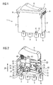
- Fig. 1 shows a perspective view of a circuit breaker 1 with a housing 2, from which bottom or bottom side contact terminals 3 to 6 protrude.
- a housing cap 2 'of the housing 2 has on the upper side a housing opening 7 in which an actuating element 8 designed as a rocker switch is mounted in a rotational or pivotable manner.
- the actuator 8 allows the manner of a manual release both the manual switch on and a manual switch off the circuit breaker.
- latching arms 9 are used for locking and thus for fixing the circuit breaker 1 in a mounting or mounting hole.
- the housing 2 is closed at the bottom of the housing with a housing base 10, which has latching elements 11 which engage in the mounting of the circuit breaker 1 in the housing cap 2 'provided for recesses 12.
- Fig. 2 shows a perspective view of the housing interior of the circuit breaker 1. All the individual components of the circuit breaker 1 are mounted on the housing base 10. Housing underside, the contact terminals 3 to 6 protrude from the housing base 10 and thus out of the circuit breaker housing 2.
- the circuit breaker 1 is provided to secure two circuits.
- a first circuit, the contact terminals 3 and 5 and the second circuit, the contact terminals 4 and 6 are assigned.
- Housing inside the circuits on the respective contact terminals 3 to 6 associated contact springs 14 and 15 can be closed and interrupted.
- the contact springs 14 and 15 are held at fixed ends 16 and 17, respectively. These opposing free ends 18,19 are in overlap with housing-side free or contact ends 20,21 of the contact terminals 3 and 4.
- the contact spring 15 is electrically conductively connected at its fixed end 17 to the contact terminal 6 and held on this.
- the contact spring 14 is held at the fixed end 16 by an intermediate piece 22 and is electrically conductively connected thereto and via a bimetal 23 coupled thereto with the contact connection 5.
- the connectable to the contact terminals 3 and 5 circuit is heat protection monitored such that a current flowing through this and the contact terminal 5 in the circuit breaker 1 first through the bimetal 23, about this through the contact spring 14 and the contact terminal 3 from the circuit breaker 1 again flows out.
- the connectable to the contact terminals 4 and 6 circuit is not heat protection monitored, as flowing through this current through the contact terminal 6 into the circuit breaker 1 and directly through the contact spring 15 and via the contact terminal 4 from this circuit breaker 1 flows out again.
- a slider 24 is provided, which is arranged in the housing base 10 between a closed position (on position) and a switch-off position (off position) displaceable. In the illustration according to Fig. 2 the slider 24 is in the off position. This can be seen at the open contacts 25 to 28 between the free ends 18,19 of the contact springs 14 and 15 and the free ends 20,21 of the contact terminals 3 and 4, respectively.
- the slider 24 is on the one hand manually displaceable by actuating the actuating element 8 both in the on position and in the off position.
- the slider 24 is on the other hand displaceable by an overcurrent trip in the off position.
- this is heated with the result that the bimetal 23 bends.
- Ausbiegens of the bimetal 23 which is in the on position locked slide 24 is released or unlatched from a snap or snap connection.
- the displacement of the slider 24 in its off position is due to the restoring force of the leaf spring-like contact springs 14, 15 in the triggering or spring force 29th
- Fig. 3 shows the circuit breaker 1 in exploded view.
- the intermediate piece 22 is shown with a first angled retaining end 30 for the contact spring 14.
- the intermediate piece 22 has a further, opposite the first holding end 30 approximately at right angles bent second holding end 31 for the bimetal 23.
- the bimetal 23 is bent approximately U-shaped and comprises two comparatively long bimetallic brackets 32a, 33a and two comparatively short bimetallic brackets 32b, 33b, two mutually spaced bimetallic legs 32, 33, which merge into one another at a bimetallic end 34 and are connected together ( Fig. 4 ).
- the holding end 31 of the intermediate piece 22 is connected to the bimetal leg 33, while the bimetal leg 32 is connected to an angled or bent free end 35 of the contact terminal 5 ( Fig. 2 ).
- an adjustment element 36 which is also referred to below as a support element, is shown, which is preferably made of plastic and is an injection-molded part executed housing base 10 is injected and thus secured thereto.
- a spring tab 36a of the adjusting element 36 can be bent in the direction of the short bimetallic brackets 32b, 33b toward adjustment or adjustment of the bimetal 23.
- the respective circuit is closable and interruptible.
- the Fig.5 and 6 show a side view of the circuit breaker 1. It is in Fig. 5 the slider 24 is positioned in the off position, whereas the slider 24 in Fig. 6 moved to the on position.
- the housing base 10 has a slide guide 37 with an upper stop 37a (FIG. Fig. 3 ) for the slider 24.
- the slider guide 37 is formed as an in a back 38 of the housing base 10 incorporated slot-like recess or recess along a displacement direction 39 of the slider 24. This closed recess 37 is limited in the release direction 29 by the slide stop 37a.
- the slider 24 engages with an integrally formed on this slider arm 40 in the recess 37 a.
- the sliding in the recess 37 to stop 37a pusher arm 40 of the slider 24 also serves as a pressure lever for acting on the contact spring 15.
- the slider 24 has a further slide arm 41 which serves as a pressure lever for acting on the contact spring 14 and in the displacement direction 39 in particular offset to the slide arm 40 is integrally formed on the slide 24.
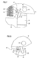
- FIGS. 7 and 8 show in an enlarged section of the FIGS. 5 and 6 the latching connection 42 of the circuit breaker 1 in the unlocked or in the locked state of the slider 24 with the actuating element 8.
- the latching connection 42 is formed by a molded on the slider 24 switching cam 43 as a first locking element and an integrally formed on the actuating element 8 locking lug 44 as a second locking element.
- the actuating element 8 is pivotally mounted about a rotatably mounted on the housing base 10 bearing pin 45 in the switching-46.
- a switching edge 47 arranged directly next to the latching nose 44 is integrally formed.
- a return of the slider 24 from the on position to the off position due to an overcurrent trip is carried out by the bending of the bimetal 23 from the drawing plane according to the Figures 2 . 5 and 6 out with the result that the latching connection 42 is automatically unlocked.
- a return spring 48 is additionally provided in the form of a coil spring between the actuator 8 and the housing base 10, the the actuator 8 automatically returns from a closed position to an open position.
- the overcurrent release is visible or recognizable from outside the housing 2.
- a spring tab 50 is provided on the actuating element 8. This moves during the return of the actuator 8 in its off position on a front side 51 of the slider 24 touching this along such that the rotated by the unlocking of the locking connection 42 counterclockwise slide 24 undergoes a reverse rotation in the neutral position.
- an unlatching element 52 in the form of a wing is integrally formed thereon for the extension of a rotary lever for the rotation of the slide 24.
- the bimetal 23 is preferably arranged transversely to the axis of rotation 49 of the slider 24 extending in the housing base 10.
- the short bimetal bars 32b, 33b of the bimetal 23 held on the long bimetallic bars 32a, 33a are bent out in the opposite direction to their direction of excursion 53.
- the short bimetallic brackets 32b, 33b rest on the adjusting element 36, so that as a result of their support on the adjusting element 36 an additional force component is generated in the direction of return 53 of the bimetal 23.
- the long bimetallic brackets 32a, 33a of the bimetal which likewise extend in the direction of return 53, are thus supported by the short bimetallic brackets 32b, 33b, in that they are supported in the opposite direction on the adjusting element 36.
- the bimetal 24 is arranged in the housing base 10 such that the short bimetallic brackets 32b, 33b facing away from the slider 24, while the long bimetallic brackets 32a, 33a facing the slider 24 and its wings 52.
- the slider vane 52 is acted upon by the first longitudinal section L1 which is in register with the slider 24 and its vane 52, and thus by the short bimetallic brackets 32b, 33b and partly by the long bimetallic brackets 32a, 33a.
- the adjusting element 36 formed in the housing base 10 is placed on a side of the bimetal 23 facing away from the slider vane 52.
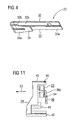
- the arrangement of the adjusting element 36 is in Fig. 11 comparatively clearly recognizable.
- Fig. 11 shows the slider 24 and the bimetal 24 in a side view.
- the spring tabs 36a is bendable via a bending point 54 on the adjusting element 36 in and counter to the direction of repositioning 53 of the bimetal 24.
- the adjusting element 36 with its spring tabs 36a serves to align the bimetal 24 in register with the wing 52 of the slider 24 and adjust such that the deflection of the bimetal 24 causes the rotation of the slider 24 and thus a reliable unlocking of the locking connection 42.
- the spring tabs 36a is deflected or bent more or less around a bending point or bending edge 54 produced by a local material weakening of the adjusting element 36 in the direction of the short bimetallic brackets 32b, 33b of the bimetal 24 and thus in the direction of recession 53.
Abstract
Description
Die Erfindung bezieht sich auf einen Schutzschalter zur Absicherung eines Stromkreises gemäß dem Oberbegriff des Anspruchs 1. Ein derartiger Schutzschalter ist aus der
Aus der Gebrauchsmusterschrift
Der Erfindung liegt die Aufgabe zugrunde, einen besonders einfach aufgebauten Schutzschalter anzugeben.The invention has for its object to provide a particularly simple circuit breaker.
Diese Aufgabe wird erfindungsgemäß gelöst durch die Merkmale des Anspruchs 1. Vorteilhafte Ausgestaltungen und Weiterbildungen sind Gegenstand der Unteransprüche.This object is achieved by the features of claim 1. Advantageous embodiments and further developments are the subject of the dependent claims.
Dazu umfasst der Schutzschalter einen mit einem Betätigungselement gekoppelten Schieber, dessen Kontaktende an der Kontaktfeder anliegt. Der im Gehäuse schiebebeweglich gehaltene Schieber beaufschlagt die Kontaktfeder entgegen deren Rückstellkraft in Kontaktstellung. Der Schieber rastet in Einschaltstellung des Schutzschalters ein. Zur Verschiebung des Schiebers in die Einschaltstellung mittels des Betätigungselements wirken Rastelemente in Form von Schaltnocken am Schieber und am Betätigungselement über eine Schaltkante zusammen.For this purpose, the circuit breaker comprises a slider coupled to an actuator, the contact end rests against the contact spring. The slider movably held in the housing acts on the contact spring counter to its restoring force in the contact position. The slide engages in closed position of the circuit breaker. For displacement of the slider in the closed position by means of the actuating element act locking elements in the form of switching cam on the slide and the actuating element via a switching edge together.
Die Ein- oder Verrastung des Schiebers und damit des zweckmäßigerweise als Schaltwippe ausgeführten Betätigungselements erfolgt nach Art einer Rast- oder Schnappverbindung. Dazu sind am Betätigungselement ein erstes Rastelement und am Schieber ein zweites Rastelement vorgesehen, wobei beim Betätigen des Betätigungselements in Einschaltrichtung die Rastelemente über die vorzugsweise am Betätigungselement vorgesehene Schaltkante in die Raststellung gleiten. Zweckmäßigerweise ist die Schaltkante unmittelbar neben der Rastnase am Betätigungselement angeformt. Der Schaltnocken fährt beim Verschieben des Schiebers in die Ein-Stellung an der Schaltkante entlang, bis der Schaltnocken hinter der Rastnase einrastet. Durch das Einrasten des Schaltnockens ist der Schieber in der Ein-Stellung arretiert.The engagement or locking of the slide and thus the appropriately designed as a rocker actuator takes place in the manner of a snap or snap connection. For this purpose, a first latching element and the slider a second latching element are provided on the actuating element, wherein upon actuation of the actuating element in the switch-on direction, the latching elements slide over the switching edge preferably provided on the actuating element into the latching position. Conveniently, the switching edge is formed directly adjacent to the locking lug on the actuating element. The switching cam moves when moving the slider in the on position along the switching edge along until the switching cam engages behind the locking lug. By locking the switching cam, the slider is locked in the on position.
Zur Entklinkung des eingerasteten Schiebers infolge einer thermischen Auslösung ist dieser zweckmäßigerweise aus einer Ausgangsposition um eine Drehachse, vorzugsweise um die Schieberlängsachse, drehbar im Gehäusesockel des Gehäuses angeordnet. Dabei trägt zweckmäßigerweise das Betätigungselement einen bei dessen Betätigung verschwenkenden Federlappen, der den gedrehten Schieber in seine Ausgangsposition zurückführt. Der zur Rückführung des aus seiner Ausgangs- oder Ruheposition heraus gedrehten Schiebers vorgesehene Federlappen kann auch innenseitig am Gehäuse angeformt sein.For unlatching the latched slide as a result of thermal activation, this is expediently arranged rotatably in the housing base of the housing from an initial position about an axis of rotation, preferably about the slide longitudinal axis. Expediently, the actuating element carries a pivoting during its operation spring tab, which returns the rotated slider to its original position. The spring flap provided for returning the slide rotated out of its starting or rest position can also be integrally formed on the housing on the inside.
In vorteilhafter Ausgestaltung sind zwei in Schieberlängsrichtung übereinander angeordnete Kontaktfedern und zwei am Kontaktende des Schiebers in Schieberlängsrichtung z. B. stufig und/oder übereinander angeordnete Kontaktarme vorgesehen, deren jeder freiendseitig an einer der Kontaktfedern anliegt.In an advantageous embodiment, two superimposed in the slider longitudinal direction of contact springs and two at the contact end of the slider in the slider longitudinal direction z. B. stage and / or superimposed contact arms provided, each of which rests against one of the free-end-side contact springs.
Zweckmäßigerweise ist das Kontaktende des Schiebers in einer Schieberführung des Gehäuses oder in dessen Gehäusesockel geführt. Zur Führung des Schiebers im Gehäuse ist eine Schieberführung mit einem Schieberanschlag vorgesehen. Als Schieberführung ist bevorzugt eine langlochartige Ausnehmung in einer Sockelwand des Gehäusesockels vorgesehen.Conveniently, the contact end of the slider is guided in a slide guide of the housing or in the housing base. To guide the slide in the housing a slide guide is provided with a slide stop. As a slide guide, a slot-like recess is preferably provided in a base wall of the housing base.
Das Betätigungselement ist zwischen einer Einschaltstellung und einer Ausschaltstellung verschwenkbar und rastet entgegen der Rückstellkraft einer Rückstellfeder in Einschaltrichtung ein. Das Gehäuse weist einen Gehäusesockel und eine auf diesen aufsetzbare Gehäusekappe auf. An dieser sind zweckmäßigerweise an gegenüberliegenden Gehäuseseiten im Bereich einer Durchführungsöffnung für das Betätigungselement zwei Rastarme zur Befestigung des Gehäuses in einer Einbauöffnung angeformt.The actuating element is pivotable between a closed position and an open position and snaps against the restoring force of a return spring in the switch-on. The housing has a housing base and a housing cap which can be placed thereon. At this are expediently at opposite Housing sides formed in the region of a passage opening for the actuating element two locking arms for fastening the housing in an installation opening.
In zweckmäßiger Weiterbildung ist am Betätigungselement eine Rückstelleinrichtung zur Rückführung des Betätigungselements in eine Ausschaltstellung vorgesehen. Die Rückstelleinrichtung, die das Betätigungselement im Falle der Überstromauslösung in dessen Ausschaltstellung zurückführt, ist vorzugsweise als Spiralfeder ausgeführt. Das zweckmäßigerweise als Schaltwippe ausgeführte Betätigungselement kann manuell sowohl in die Einschaltstellung als auch nach Art eines Handauslöser in die Ausschaltstellung geführt werden.In an expedient development, a return device for returning the actuating element to an off position is provided on the actuating element. The restoring device, which returns the actuating element in the event of overcurrent release in its open position, is preferably designed as a spiral spring. The appropriately designed as a rocker actuator can be performed manually both in the closed position and in the manner of a manual release in the off position.
Eine Überstromauslösung des Schutzschalters ist am in Ausschaltstellung befindlichen Betätigungselement von außerhalb des Gehäuses erkennbar. An der Schaltstellung des Betätigungselements ist besonders einfach erkennbar, ob der durch den Schutzschalter abgesicherte Stromkreis geschlossen oder unterbrochen ist.An overcurrent release of the circuit breaker can be seen on the actuator located in the off position from outside the housing. At the switching position of the actuating element is particularly easy to see whether the hedged by the circuit breaker circuit is closed or interrupted.
Gemäß einer vorteilhaften Ausgestaltung ist der Schutzschalter zur Absicherung mehrerer Stromkreise ausgebildet. Dazu weist der Schutzschalter für jeden weiteren Stromkreis aus dem Gehäuse herausragende Kontaktanschlüsse auf. Zweckmäßigerweise ist für jeden weiteren Stromkreis jeweils eine Kontaktfeder vorgesehen, die mit dem jeweiligen zugeordneten Kontaktanschluss gehäuseintem elektrisch leitend verbunden und von diesem gehalten ist. Mit dem zweiten, demselben Stromkreis zugeordneten Flachstecker ist die Kontaktfeder in Überdeckung kontaktierbar. Zum Schließen und Öffnen des Stromkreises wird die jeweilige Kontaktfeder entgegen deren Federkraftrichtung mittels des entsprechenden Kontakt- oder Schieberarms des Schiebers beaufschlagt. Dazu sind am Schieber in Schieberlängsrichtung in unterschiedlichen Ebenen, z. B. stufig oder direkt übereinander angeordnete Kontaktarme vorgesehen, von denen jeweils ein Kontaktarm an einer der in Schieberlängsrichtung übereinander angeordneten Kontaktfedern anliegt.According to an advantageous embodiment of the circuit breaker is designed to protect multiple circuits. For this purpose, the circuit breaker for each additional circuit from the housing outstanding contact terminals. Expediently, a contact spring is provided in each case for each further circuit, which is connected electrically conductively to the respective associated contact connection and held by the latter. With the second, the same circuit associated tab, the contact spring can be contacted in coverage. To close and open the circuit, the respective contact spring is acted against the spring force direction by means of the corresponding contact or slide arm of the slider. These are on slide in slide longitudinal direction in different planes, z. B. stage or directly superimposed contact arms provided, of which in each case a contact arm rests on one of the slider longitudinal direction arranged one above the other contact springs.
Die mit der Erfindung erzielten Vorteile bestehen insbesondere darin, dass mittels des gehäuseintem geführten Schiebers mehrere Funktionen eines Schutzschalters durchführbar sind, so dass dieser besonders einfach aufgebaut sein kann. So dient das am Schieber angeformte Rastelement in Form eines Schaltnockens als Schaltschloss zur Arretierung des Schiebers in der Einschaltstellung (Ein-Stellung) bei geschlossenem Stromkreis. Der Schaltnocken dient zudem der Verschiebung des Schiebers von der Ausschaltstellung (Aus-Stellung) in die Ein-Stellung.The advantages achieved by the invention are in particular that by means of gehäuseintem guided slide several functions of a circuit breaker feasible are so that this can be very simple. Thus, the integrally formed on the slide locking element in the form of a switching cam as a switching lock for locking the slide in the closed position (on-position) with closed circuit. The switching cam also serves to shift the slider from the open position (off position) to the on position.
Durch Betätigen des Betätigungselements in Einschaltrichtung fährt der Schaltnocken an der unmittelbar neben dem korrespondierenden Rastelement des Betätigungselements platzierten Schaltkante entlang. Des Weiteren ist der Schieber mittels des Betätigungselements manuell in die Ein- sowie in die Aus-Stellung verschiebbar. Ferner dient der Schieber als Kontaktschalter zum Öffnen und Schließen des Stromkreises. Die zusätzliche Drehfunktion des Schiebers dient zur Entriegelung einer diesen in der Ein-Stellung arretierenden Rast- oder Schnappverbindung oder eines Rastgesperres im Falle einer Überstromauslösung.By actuating the actuating element in the switching-on direction, the switching cam moves along the switching edge placed immediately next to the corresponding locking element of the actuating element. Furthermore, the slider is manually displaceable by means of the actuating element in the on and in the off position. Further, the slider serves as a contact switch for opening and closing the circuit. The additional rotary function of the slide is used to unlock a locking in the on position locking or snap connection or a Rastgesperres in the event of overcurrent tripping.
Zur thermischen Auslösung des Schutzschalters kann der Schieber mit einem Bimetall gekoppelt sein. Dieses kann elektrisch zwischen den ersten Kontaktanschluss und über die Kontaktfeder an den zweiten Kontaktanschluss geschaltet sein. Eine im Gehäuse angeordnete Justiereinheit mit einer Biegestelle ermöglicht eine manuelle Justierung des Bimetalls. Das bevorzugt quer zur Schieberlängsrichtung verlaufend im Gehäuse bzw. im Gehäusesockel angeordnete Bimetall weist zwei Längsabschnitte auf, von denen ein erster Längsabschnitt mit dem Schieber zumindest teilweise derart in Überdeckung ist, dass das Bimetall den Schieber infolge eines Überstromes zur Kontaktöffnung entklinkt. Hierzu ist an den Schieber zweckmäßigerweise das Entklinkungselement in Form des flügelartigen Federlappens angeformt, der sich entlang des ersten Längsabschnitts des Bimetalls erstreckt. Der Federlappen dient als verlängerter Drehhebel und ist infolge eines Ausbiegens des Bimetalls von diesem zur Drehung des Schiebers beaufschlagt. Durch Drehung des Schiebers infolge der Überstromauslösung wird das durch die Rastnase und den Schaltnocken gebildete Rastgesperre entriegelt. Infolge dessen wird der in der Ein-Stellung befindliche Schieber von der Kontaktfeder parallel zur Federkraftrichtung in die Aus-Stellung verschoben. Dabei öffnet sich der Kontakt zwischen Kontaktfeder und dem zweiten Kontaktanschluss.For thermal tripping of the circuit breaker, the slide can be coupled with a bimetal. This can be connected electrically between the first contact terminal and via the contact spring to the second contact terminal. An adjusting unit arranged in the housing with a bending point allows a manual adjustment of the bimetal. The bimetal preferably arranged transversely to the slide longitudinal direction in the housing or in the housing base has two longitudinal sections, of which a first longitudinal section is at least partially in register with the slide such that the bimetal unlatches the slide due to an overcurrent to the contact opening. For this purpose, the unlatching element in the form of the wing-like spring lobe is expediently formed on the slide, which extends along the first longitudinal section of the bimetal. The spring tab serves as an extended rotary lever and is acted upon as a result of bending out of the bimetal of this for rotation of the slider. By rotation of the slider due to the overcurrent release the locking mechanism formed by the latching lug and the switching cam is unlocked. As a result, the slider located in the on position is moved by the contact spring parallel to the spring force direction in the off position. In this case, the contact between the contact spring and the second contact connection opens.
Durch die Verwendung des multifunktionalen Schiebers weist der Schutzschalter eine vergleichsweise geringe Anzahl von Einzelbauteilen auf. Dadurch wird eine besonders einfache Fertigung des Schutzschalters ermöglicht.By using the multifunctional slider, the circuit breaker has a comparatively small number of individual components. This allows a particularly simple production of the circuit breaker.
Nachfolgend wird ein Ausführungsbeispiel der Erfindung anhand einer Zeichnung näher erläutert. Darin zeigen:
- Fig. 1
- in perspektivischer Darstellung einen Schutzschalter mit aus einem Gehäuse herausragenden Kontaktanschlüssen,
- Fig. 2
- in perspektivischer Darstellung das Gehäuseinnere des Schutz- schalters gemäß
Fig. 1 , - Fig. 3
- in Explosionsdarstellung Einzelbauteile des Schutzschalters,
- Fig. 4
- in perspektivischer Darstellung ein Bimetall des Schutzschalters,
- Fig. 5 und 6
- eine Seitenansicht des Schutzschalters gemäß
Fig. 2 mit einem Schieber in Aus-Stellung bzw. in Ein-Stellung, - Fig. 7 und 8
- Ausschnitte aus den
Fig. 5 und Fig. 6 in größerem Maßstab mit dem Schieber in Aus-Stellung bzw. in Ein-Stellung, - Fig. 9
und 10 - in Draufsicht auf den Schieber dessen neutrale und gedrehte Stel- lung mit ver- bzw. entriegelter Rastverbindung gemäß
Fig. 6 , und - Fig. 11
- in einer Seitenansicht den Schieber in Neutralstellung mit verriegel- ter Rastverbindung gemäß
Fig. 9 .
- Fig. 1
- a perspective view of a circuit breaker with protruding from a housing contact terminals,
- Fig. 2
- in a perspective view of the housing interior of the circuit breaker according to
Fig. 1 . - Fig. 3
- in exploded view, individual components of the circuit breaker,
- Fig. 4
- in perspective a bimetal of the circuit breaker,
- FIGS. 5 and 6
- a side view of the circuit breaker according to
Fig. 2 with a slide in the off position or in the on position, - FIGS. 7 and 8
- Cutouts from the
Fig. 5 and Fig. 6 on a larger scale with the slide in the off position or in the on position, - FIGS. 9 and 10
- in a plan view of the slider whose neutral and rotated position with locked or unlocked locking connection according to
Fig. 6 , and - Fig. 11
- in a side view of the slide in neutral position with locked locking connection according to
Fig. 9 ,
Einander entsprechende Teile sind in allen Figuren mit den gleichen Bezugszeichen versehen.Corresponding parts are provided in all figures with the same reference numerals.
Am Gehäuse 2 vorgesehene Rastarme 9 dienen zur Verrastung und somit zur Fixierung des Schutzschalters1 in einer Einbau- oder Montageöffnung. Das Gehäuse 2 ist gehäuseunterseitig mit einem Gehäusesockel 10 abgeschlossen, welcher Rastelemente 11 aufweist, die bei der Montage des Schutzschalters 1 in an der Gehäusekappe 2' vorgesehene Aussparungen 12 einrasten.On the
Der Schutzschalter 1 ist zur Absicherung von zwei Stromkreisen vorgesehen. Einem ersten Stromkreis sind die Kontaktanschlüsse 3 und 5 und dem zweiten Stromkreis sind die Kontaktanschlüsse 4 und 6 zugeordnet. Gehäuseinnenseitig sind die Stromkreise über den jeweiligen Kontaktanschlüssen 3 bis 6 zugeordnete Kontaktfedern 14 und 15 schließ- und unterbrechbar. Die Kontaktfedern 14 und 15 sind an Festenden 16 bzw. 17 gehalten. Diesen gegenüberliegende Freienden 18,19 stehen in Überdeckung mit gehäuseinnenseitigen Frei- oder Kontaktenden 20,21 der Kontaktanschlüsse 3 bzw. 4. Die Kontaktfeder 15 ist an ihrem Festende 17 mit dem Kontaktanschluss 6 elektrisch leitend verbunden und an diesem gehalten. Die Kontaktfeder 14 ist am Festende 16 von einem Zwischenstück 22 gehalten und über dieses sowie über ein mit diesem gekoppeltes Bimetall 23 mit dem Kontaktanschluss 5 elektrisch leitend verbunden.The circuit breaker 1 is provided to secure two circuits. A first circuit, the
Der an die Kontaktanschlüsse 3 und 5 anschließbare Stromkreis ist hitzeschutzüberwacht derart, dass ein durch diesen und über den Kontaktanschluss 5 in den Schutzschalter 1 fließender Strom zunächst durch das Bimetall 23, über dieses durch die Kontaktfeder 14 und über den Kontaktanschluss 3 aus dem Schutzschalter 1 wieder herausfließt. Im Gegensatz dazu ist der an die Kontaktanschlüsse 4 und 6 anschließbare Stromkreis nicht hitzeschutzüberwacht, da ein durch diesen fließender Strom über den Kontaktanschluss 6 in den Schutzschalter 1 hinein und direkt über die Kontaktfeder 15 und über den Kontaktanschluss 4 aus diesem Schutzschalter 1 wieder herausfließt. Zum Schließen und Unterbrechen des jeweiligen Stromkreises ist ein Schieber 24 vorgesehen, der im Gehäusesockel 10 zwischen einer Einschaltstellung (Ein-Stellung) und einer Ausschaltstellung (Aus-Stellung) verschiebbar angeordnet ist. In der Darstellung gemäß
Der Schieber 24 ist einerseits durch Betätigen des Betätigungselements 8 sowohl in die Ein-Stellung als auch in die Aus-Stellung manuell verschiebbar. Der Schieber 24 ist andererseits durch eine Überstromauslösung in die Aus-Stellung verschiebbar. Im Falle eines durch das Bimetall 23 fließenden Überstroms wird dieses mit der Folge erhitzt, dass sich das Bimetall 23 ausbiegt. Infolge dieses Ausbiegens des Bimetalls 23 wird der in der Ein-Stellung befindliche arretierte Schieber 24 aus einer Rast- oder Schnappverbindung gelöst oder entklinkt. Die Verschiebung des Schiebers 24 in dessen Aus-Stellung erfolgt aufgrund der Rückstellkraft der blattfederartigen Kontaktfedern 14, 15 in deren Auslöse- oder Federkraftrichtung 29.The
Das Bimetall 23 ist etwa U-förmig gebogen und umfasst unter Bildung von zwei vergleichsweise langen Bimetallbügeln 32a,33a und zwei vergleichsweise kurzen Bimetallbügeln 32b,33b zwei zueinander beabstandet verlaufende Bimetallschenkel 32 ,33, die an einem Bimetallende 34 ineinander übergehen und dort miteinander verbunden sind (
In
Die
Der Schieber 24 greift mit einem an diesem angeformten Schieberarm 40 in die Ausnehmung 37 ein. Der in der Ausnehmung 37 bis zum Anschlag 37a verschiebbare Schieberarm 40 des Schiebers 24 dient zusätzlich als Druckhebel zur Beaufschlagung der Kontaktfeder 15. Der Schieber 24 weist einen weiteren Schieberarm 41 auf, der als Druckhebel zur Beaufschlagung der Kontaktfeder 14 dient und in Verschiebungsrichtung 39 insbesondere parallel versetzt zum Schieberarm 40 am Schieber 24 angeformt ist.The
In der Aus-Stellung des Schiebers 24 sind die Kontakte 25,26 zwischen der Kontaktfeder 14 und dem Kontaktanschluss 3 sowie die Kontakte 27,28 zwischen der Kontaktfeder 15 und dem Kontaktanschluss 4 offen. In der Aus-Stellung des Schiebers 24 (
Um den Schieber 24 aus der in
Eine Rückführung des Schiebers 24 von der Ein-Stellung in die Aus-Stellung aufgrund einer Überstromauslösung erfolgt durch das Ausbiegen des Bimetalls 23 aus der Zeichenebene gemäß den
Wie aus den
Um eine zuverlässige Entriegelung der Rastverbindung 42 durch Drehung des Schiebers 24 zu bewirken, ist zur Verlängerung eines Drehhebels für die Drehung des Schiebers 24 an diesem ein Entklinkungselement 52 in Form eines Flügels angeformt. Das Bimetall 23 ist vorzugsweise quer zur Drehachse 49 des Schiebers 24 verlaufend im Gehäusesockel 10 angeordnet. Dabei ist ein erster Längsabschnitt L1 des zwei Längsabschnitte L1 und L2 aufweisenden Bimetalls 23 mit dem Schieber 24 und dessen Flügel 52 in Überdeckung, um den verrasteten oder verriegelten Schieber 24 zu entklinken.In order to effect a reliable unlocking of the latching
Im Falle einer Überstromauslösung werden dabei die kurzen Bimetallbügel 32b, 33b des an den langen Bimetallbügeln 32a,33a gehaltenen Bimetalls 23 entgegen dessen Ausbiegerichtung 53 ausgebogen. Dabei liegen die kurzen Bimetallbügel 32b, 33b am Justierelement 36 an, so dass infolge deren Abstützung am Justierelement 36 eine zusätzliche Kraftkomponente in Ausbiegerichtung 53 des Bimetalls 23 erzeugt wird. Die sich ebenfalls in Ausbiegerichtung 53 ausbiegenden langen Bimetallbügel 32a, 33a des Bimetalls werden somit durch die kurzen Bimetallbügel 32b, 33b unterstützt, indem sich diese in entgegengesetzter Richtung am Justierelement 36 abstützen.In the event of overcurrent tripping, the short
Das Bimetall 24 ist im Gehäusesockel 10 derart angeordnet, dass die kurzen Bimetallbügel 32b,33b vom Schieber 24 abgewandt sind, während die langen Bimetallbügel 32a,33a dem Schieber 24 und dessen Flügel 52 zugewandt sind. Der Schieberflügel 52 ist beim Ausbiegen des Bimetalls 24 vom ersten mit dem Schieber 24 und dessen Flügel 52 in Überdeckung stehenden Längsabschnitt L1 und somit von den kurzen Bimetallbügeln 32b,33b und teilweise von den langen Bimetallbügeln 32a, 33a beaufschlagt.The bimetal 24 is arranged in the
Um die Auslösekraft des Bimetalls 24 zur zuverlässigen Entriegelung der Rastverbindung 42 bei einer Überstromauslösung zu erhöhen, ist das in den Gehäusesockel 10 eingeformte Justierelement 36 an einer dem Schieberflügel 52 abgewandten Seite des Bimetalls 23 platziert. Die Anordnung des Justierelementes 36 ist in
- 11
- Schutzschalterbreaker
- 22
- Gehäusecasing
- 2'2 '
- Gehäusekappehousing cap
- 3 bis 63 to 6
- KontaktanschlussContact Termination
- 77
- Gehäuseöffnunghousing opening
- 88th
- Betätigungselementactuator
- 99
- Rastelementelocking elements
- 1010
- Gehäusesockelhousing base
- 1111
- Rastelementelocking elements
- 1212
- Aussparungrecess
- 14,1514.15
- Kontaktfedercontact spring
- 16,1716.17
- Festendefixed end
- 18,1918.19
- Freiendefree end
- 2222
- Zwischenstückconnecting piece
- 2323
- Bimetallbimetallic
- 2424
- Schieberpusher
- 2525
- KontaktContact
- 2626
- KontaktContact
- 2727
- KontaktContact
- 2828
- KontaktContact
- 2929
- Auslöserichtungtripping direction
- 30,3130.31
- Halteendeholding end
- 3232
- BimetalischenkelBimetalischenkel
- 32a,b32a, b
- BimetallbügelBimetallbügel
- 33a,b33a, b
- BimetallbügelBimetallbügel
- 3434
- BimetallendeBimetallende
- 3535
- Freiendefree end
- 3636
- Justierelementadjusting
- 36a36a
- Federlappenspring tabs
- 3737
- Schieberführung/AusnehmungSlider guide / recess
- 37a37a
- Schieberanschlagslide stop
- 3838
- Rückseiteback
- 3939
- Verschiebungsrichtungshift direction
- 40,4140.41
- Schieberarmpusher
- 4242
- Schnapp-/RastverbindungSnap / latch connection
- 4343
- erstes Rastelement/ Schaltnockenfirst locking element / switching cam
- 4444
- zweites Rastelement/ Rastnasesecond locking element / locking lug
- 4545
- Lagerzapfenpivot
- 4646
- Einschaltrichtungswitching-on
- 4747
- Schaltkanteswitching edge
- 4848
- RückstellfederReturn spring
- 4949
- Dreh-/SchieberlängsachseRotary / slide longitudinal axis
- 5050
- Federlappenspring tabs
- 5151
- Vorderseitefront
- 5252
- Schieberflügelslide wings
- 5353
- AusbiegerichtungAusbiegerichtung
- 5454
- Biegestelle/-kanteBend / Edge
- L1,2L1,2
- Längsabschnittlongitudinal section
Claims (7)
- Circuit breaker (1) for securing a circuit, with an operating element (8) and with contact connectors (3 to 6), protruding from a housing (2, 10), and with a contact spring (14), which is linked electrically conductive to a first contact connector (5) and overlaps at the free end the second contact connector (3) which is contactable, characterized by a slider (24) - guided in a slidingly movable manner in the housing (2, 10) and locked with the operating element (8) in an energized position - whose contact end (40, 41) is adjacent to the contact spring (14) and loads it in contact position against its restoring force.
- Circuit breaker according to claim 1, characterized in that for the forming of the locking connection (42) of the slider (24) in an energized position a first locking element (44) is foreseen at the operating element (8) and a second locking element (43) is foreseen at the slider (24).
- Circuit breaker according to claim 2, characterized in that when activating the operating element (8) into the energized direction (46) the locking elements (43, 44) glide over a switching edge (47) into the locking position.
- Circuit breaker according to one of the claims 1 to 3, characterized in that the contact end (40) of the slider (24) is guided in a slider guidance (37) of the housing (2, 10).
- Circuit breaker according to one of the claims 1 to 4, characterized in that the unlatching of the locked-in slider (24) the slider (24) is arranged in the housing (2, 10) rotably around its longitudinal axis (49) from an initial position.
- Circuit breaker according to claim 5, characterized by a spring tab (50), moulded to the operating element (8) and returning the turned slider (24) into its initial position.
- Circuit breaker according to one of the claims1 to 6, characterized in that for guiding the slider (24) in the housing (2, 10) a slider guidance (37) with a slider stop member (37a) is foreseen.
Priority Applications (1)
| Application Number | Priority Date | Filing Date | Title |
|---|---|---|---|
| PL10007784T PL2246871T3 (en) | 2005-03-12 | 2006-02-03 | Circuit breaker for securing a circuit |
Applications Claiming Priority (3)
| Application Number | Priority Date | Filing Date | Title |
|---|---|---|---|
| DE202005004002 | 2005-03-12 | ||
| DE200520004409 DE202005004409U1 (en) | 2005-03-18 | 2005-03-18 | Protective circuit breaker with actuating element and contact terminals, protruding from housing, with contact spring conductively coupled to first terminal while its free end can contact sectond terminal |
| EP06706602A EP1859466B1 (en) | 2005-03-12 | 2006-02-03 | Protective circuit breaker for protecting an electric circuit |
Related Parent Applications (1)
| Application Number | Title | Priority Date | Filing Date |
|---|---|---|---|
| EP06706602.7 Division | 2006-02-03 |
Publications (2)
| Publication Number | Publication Date |
|---|---|
| EP2246871A1 EP2246871A1 (en) | 2010-11-03 |
| EP2246871B1 true EP2246871B1 (en) | 2011-10-26 |
Family
ID=36129659
Family Applications (2)
| Application Number | Title | Priority Date | Filing Date |
|---|---|---|---|
| EP06706602A Not-in-force EP1859466B1 (en) | 2005-03-12 | 2006-02-03 | Protective circuit breaker for protecting an electric circuit |
| EP10007784A Not-in-force EP2246871B1 (en) | 2005-03-12 | 2006-02-03 | Circuit breaker for securing a circuit |
Family Applications Before (1)
| Application Number | Title | Priority Date | Filing Date |
|---|---|---|---|
| EP06706602A Not-in-force EP1859466B1 (en) | 2005-03-12 | 2006-02-03 | Protective circuit breaker for protecting an electric circuit |
Country Status (8)
| Country | Link |
|---|---|
| US (1) | US7312687B2 (en) |
| EP (2) | EP1859466B1 (en) |
| KR (1) | KR101007081B1 (en) |
| CN (1) | CN1993791B (en) |
| AT (2) | ATE531065T1 (en) |
| CA (1) | CA2573954C (en) |
| PL (2) | PL1859466T3 (en) |
| WO (1) | WO2006097164A1 (en) |
Cited By (1)
| Publication number | Priority date | Publication date | Assignee | Title |
|---|---|---|---|---|
| DE202015000933U1 (en) | 2014-03-21 | 2015-04-20 | Ellenberger & Poensgen Gmbh | Circuit breaker to protect a circuit |
Families Citing this family (8)
| Publication number | Priority date | Publication date | Assignee | Title |
|---|---|---|---|---|
| US7525054B2 (en) * | 2006-07-03 | 2009-04-28 | Swann Industries Pte Ltd. | Interlock door switch |
| TWM322054U (en) * | 2007-05-18 | 2007-11-11 | Tzan-Chi Chen | Over-current protecting switch |
| US7755465B2 (en) * | 2008-04-23 | 2010-07-13 | Sun-Lite Sockets Industry Inc. | Temperature control switch |
| KR200461084Y1 (en) * | 2010-08-25 | 2012-06-21 | 주식회사 케이원 코퍼레이션 | Switch |
| CN102568928B (en) * | 2012-01-18 | 2015-03-18 | 钻宝电子有限公司 | Temperature sensitive controller |
| WO2015120951A1 (en) * | 2014-02-13 | 2015-08-20 | Ellenberger & Poensgen Gmbh | Thermal overcurrent circuit breaker |
| US11189447B2 (en) * | 2014-03-28 | 2021-11-30 | Yaowu Hua | Time switch of controllable time adjustment |
| CN105013611B (en) * | 2015-07-22 | 2017-06-20 | 宁波哲恺电器有限公司 | A kind of high voltage electrostatic discharge mechanism of electrostatic air cleaner |
Family Cites Families (33)
| Publication number | Priority date | Publication date | Assignee | Title |
|---|---|---|---|---|
| BE478775A (en) | 1944-02-16 | |||
| DE2353415C2 (en) * | 1973-10-25 | 1975-05-28 | Ellenberger & Poensgen Gmbh, 8503 Altdorf | Overcurrent switch with thermal release - |
| FR2435801A1 (en) * | 1978-09-05 | 1980-04-04 | Weber Ag Fab Elektro | BIPOLAR PROTECTION CIRCUIT BREAKER WITH THERMAL TRIGGER |
| DE2928277C2 (en) * | 1979-07-13 | 1983-12-01 | Ellenberger & Poensgen Gmbh, 8503 Altdorf | Combinable two-pole overcurrent circuit breaker |
| US4338586A (en) * | 1980-09-03 | 1982-07-06 | Heinemann Electric Company | Circuit protector having a slidable latch |
| US4345233A (en) * | 1981-03-02 | 1982-08-17 | Eaton Corporation | Manual switch with timed electro-thermal latch release |
| US4528538A (en) * | 1984-01-13 | 1985-07-09 | Andersen James H | Combined switch and circuit breaker |
| EP0249595A1 (en) * | 1985-11-27 | 1987-12-23 | Slater Electric, Inc. | Unitary switch and circuit breaker |
| FR2605142B1 (en) * | 1986-10-14 | 1990-06-01 | Mors | ELECTRICAL SWITCH PROVIDED WITH PROTECTION MEANS, ESPECIALLY AGAINST SPRAY WATER |
| US4922219A (en) * | 1989-07-17 | 1990-05-01 | Mechanical Products, Inc. | Circuit breaker |
| US5089799A (en) * | 1991-01-25 | 1992-02-18 | Sorenson Richard W | Thermal switch/breaker |
| US5223813A (en) * | 1991-11-18 | 1993-06-29 | Potter & Brumfield, Inc. | Circuit breaker rocker actuator switch |
| US5264817A (en) * | 1993-02-11 | 1993-11-23 | Sorenson Richard W | Thermal circuit protective device |
| ES2115086T3 (en) | 1993-03-17 | 1998-06-16 | Ellenberger & Poensgen | PROTECTION SWITCH. |
| ATE151566T1 (en) * | 1993-03-17 | 1997-04-15 | Ellenberger & Poensgen | DEVICE SWITCH WITH INTEGRATED OVERCURRENT PROTECTION |
| US5760672A (en) * | 1997-05-02 | 1998-06-02 | Wang; Ming-Shan | Safety switch built-in with protecting circuit |
| US5892426A (en) * | 1998-06-12 | 1999-04-06 | Huang; Tse-Chuan | Safety switch with security structure |
| TW427544U (en) * | 1999-06-24 | 2001-03-21 | You Tsung Mou | Pressing-key switch with overload protection function |
| TW453504U (en) * | 1999-06-24 | 2001-09-01 | You Tsung Mou | Button switch having overload protection function |
| TW456574U (en) * | 1999-10-29 | 2001-09-21 | You Tsung Mou | Overload protection push button switch with indirectly driven auto-reset activated mechanism |
| US6307460B1 (en) * | 2000-02-01 | 2001-10-23 | Tsung-Mou Yu | Power switch device |
| US6275134B1 (en) * | 2000-03-01 | 2001-08-14 | Tsan-Chi Chen | Safety switch with a rocker type actuator and trip-off contact |
| US6400250B1 (en) * | 2000-07-14 | 2002-06-04 | Tsung-Mou Yu | Safety switch |
| US6563414B2 (en) * | 2001-04-19 | 2003-05-13 | Tsung-Mou Yu | Switch having a bimetal plate with two legs |
| US6552644B2 (en) * | 2001-07-17 | 2003-04-22 | Tsung-Mou Yu | Safety press-button switch |
| US6714116B1 (en) * | 2002-01-22 | 2004-03-30 | Rototech Electrical Components, Inc. | Circuit breaker switch |
| US6621402B2 (en) * | 2002-01-23 | 2003-09-16 | Albert Huang | Circuit breaker |
| US6617952B1 (en) * | 2002-02-26 | 2003-09-09 | Tsung-Mou Yu | Switch with adjustable spring |
| US6674033B1 (en) * | 2002-08-21 | 2004-01-06 | Ming-Shan Wang | Press button type safety switch |
| US6664884B1 (en) * | 2002-08-24 | 2003-12-16 | Tsung-Mou Yu | Dual-circuit switch structure with overload protection |
| US6734779B2 (en) * | 2002-08-24 | 2004-05-11 | Tsung-Mou Yu | Switch structure with overload protection |
| US6788186B1 (en) * | 2003-05-31 | 2004-09-07 | Tsung-Mou Yu | Activation mechanism for switch devices |
| US6933455B1 (en) * | 2004-04-28 | 2005-08-23 | Tsung-Mou Yu | Circuit breaker on a pushbutton switch |
-
2006
- 2006-02-03 EP EP06706602A patent/EP1859466B1/en not_active Not-in-force
- 2006-02-03 PL PL06706602T patent/PL1859466T3/en unknown
- 2006-02-03 AT AT10007784T patent/ATE531065T1/en active
- 2006-02-03 KR KR1020077002071A patent/KR101007081B1/en not_active IP Right Cessation
- 2006-02-03 EP EP10007784A patent/EP2246871B1/en not_active Not-in-force
- 2006-02-03 AT AT06706602T patent/ATE532200T1/en active
- 2006-02-03 CN CN2006800005475A patent/CN1993791B/en not_active Expired - Fee Related
- 2006-02-03 PL PL10007784T patent/PL2246871T3/en unknown
- 2006-02-03 WO PCT/EP2006/000933 patent/WO2006097164A1/en not_active Application Discontinuation
- 2006-02-03 CA CA2573954A patent/CA2573954C/en not_active Expired - Fee Related
-
2007
- 2007-03-16 US US11/725,219 patent/US7312687B2/en not_active Expired - Fee Related
Cited By (1)
| Publication number | Priority date | Publication date | Assignee | Title |
|---|---|---|---|---|
| DE202015000933U1 (en) | 2014-03-21 | 2015-04-20 | Ellenberger & Poensgen Gmbh | Circuit breaker to protect a circuit |
Also Published As
| Publication number | Publication date |
|---|---|
| PL2246871T3 (en) | 2012-03-30 |
| EP1859466B1 (en) | 2011-11-02 |
| EP2246871A1 (en) | 2010-11-03 |
| KR101007081B1 (en) | 2011-01-11 |
| ATE532200T1 (en) | 2011-11-15 |
| US7312687B2 (en) | 2007-12-25 |
| KR20070118579A (en) | 2007-12-17 |
| CA2573954A1 (en) | 2006-09-21 |
| US20070170047A1 (en) | 2007-07-26 |
| PL1859466T3 (en) | 2012-03-30 |
| WO2006097164A1 (en) | 2006-09-21 |
| EP1859466A1 (en) | 2007-11-28 |
| CA2573954C (en) | 2011-11-01 |
| CN1993791A (en) | 2007-07-04 |
| CN1993791B (en) | 2010-06-09 |
| ATE531065T1 (en) | 2011-11-15 |
Similar Documents
| Publication | Publication Date | Title |
|---|---|---|
| EP2246871B1 (en) | Circuit breaker for securing a circuit | |
| EP0543208B1 (en) | Protective circuit-breaker with rocker | |
| EP1760747B1 (en) | Electric circuit breaker | |
| EP1760748B1 (en) | Electrical switching device | |
| EP1405325B1 (en) | Switching device comprising a latch mechanism | |
| EP1728260B1 (en) | Switch mechanism for an electrical installation switch device | |
| EP1812944A1 (en) | Electrical installation switching device | |
| DE102008062527B4 (en) | Multi-phase electrical switching device with a trip slide and a trip slide | |
| DE10032323A1 (en) | Low voltage circuit breaker mechanism, has moving section with moving section plunger to turn shaft, together with switch section including switch shaft and spring applying turning force. | |
| EP0391086B1 (en) | Push button operated overload circuit breaker | |
| DE202010009421U1 (en) | Electrical overcurrent relay in modular design | |
| EP0500138B1 (en) | Protective switch | |
| EP0408982B1 (en) | Overcurrent circuit breaker | |
| DE202005004409U1 (en) | Protective circuit breaker with actuating element and contact terminals, protruding from housing, with contact spring conductively coupled to first terminal while its free end can contact sectond terminal | |
| WO2003007321A1 (en) | Switching device comprising a latching mechanism | |
| EP0849759B1 (en) | Switchgear for an electric installation | |
| DE102014003421A1 (en) | Electrical overcurrent relay | |
| EP0043406B1 (en) | Protective switch element to be added to an on/off switch apparatus built as a rotary switch | |
| EP1126488B1 (en) | Selective switch especially electrical main line protection switch | |
| DE2532734A1 (en) | Multi-pole pressure switch with thermal overload trip - is fitted with trip-free release and has lever hinged on push-button shaft | |
| WO2003041100A2 (en) | Electric switch | |
| EP0851449B1 (en) | Switchgear for an electric installation | |
| EP0491250A2 (en) | Installation apparatus | |
| EP1643525B1 (en) | Adjusting module for an overcurrent tripping device of a protection circuit breaker | |
| EP0473619A1 (en) | Switching mechanism for a line protective switch. |
Legal Events
| Date | Code | Title | Description |
|---|---|---|---|
| PUAI | Public reference made under article 153(3) epc to a published international application that has entered the european phase |
Free format text: ORIGINAL CODE: 0009012 |
|
| 17P | Request for examination filed |
Effective date: 20100812 |
|
| AC | Divisional application: reference to earlier application |
Ref document number: 1859466 Country of ref document: EP Kind code of ref document: P |
|
| AK | Designated contracting states |
Kind code of ref document: A1 Designated state(s): AT BE BG CH CY CZ DE DK EE ES FI FR GB GR HU IE IS IT LI LT LU LV MC NL PL PT RO SE SI SK TR |
|
| GRAP | Despatch of communication of intention to grant a patent |
Free format text: ORIGINAL CODE: EPIDOSNIGR1 |
|
| RIC1 | Information provided on ipc code assigned before grant |
Ipc: H01H 73/26 20060101AFI20110516BHEP |
|
| GRAS | Grant fee paid |
Free format text: ORIGINAL CODE: EPIDOSNIGR3 |
|
| GRAA | (expected) grant |
Free format text: ORIGINAL CODE: 0009210 |
|
| AC | Divisional application: reference to earlier application |
Ref document number: 1859466 Country of ref document: EP Kind code of ref document: P |
|
| AK | Designated contracting states |
Kind code of ref document: B1 Designated state(s): AT BE BG CH CY CZ DE DK EE ES FI FR GB GR HU IE IS IT LI LT LU LV MC NL PL PT RO SE SI SK TR |
|
| REG | Reference to a national code |
Ref country code: GB Ref legal event code: FG4D Free format text: NOT ENGLISH |
|
| REG | Reference to a national code |
Ref country code: CH Ref legal event code: EP |
|
| REG | Reference to a national code |
Ref country code: IE Ref legal event code: FG4D |
|
| REG | Reference to a national code |
Ref country code: DE Ref legal event code: R096 Ref document number: 502006010497 Country of ref document: DE Effective date: 20111229 |
|
| REG | Reference to a national code |
Ref country code: CH Ref legal event code: NV Representative=s name: E. BLUM & CO. AG PATENT- UND MARKENANWAELTE VSP |
|
| REG | Reference to a national code |
Ref country code: NL Ref legal event code: T3 |
|
| REG | Reference to a national code |
Ref country code: SE Ref legal event code: TRGR |
|
| LTIE | Lt: invalidation of european patent or patent extension |
Effective date: 20111026 |
|
| REG | Reference to a national code |
Ref country code: PL Ref legal event code: T3 |
|
| PG25 | Lapsed in a contracting state [announced via postgrant information from national office to epo] |
Ref country code: LT Free format text: LAPSE BECAUSE OF FAILURE TO SUBMIT A TRANSLATION OF THE DESCRIPTION OR TO PAY THE FEE WITHIN THE PRESCRIBED TIME-LIMIT Effective date: 20111026 Ref country code: IS Free format text: LAPSE BECAUSE OF FAILURE TO SUBMIT A TRANSLATION OF THE DESCRIPTION OR TO PAY THE FEE WITHIN THE PRESCRIBED TIME-LIMIT Effective date: 20120226 |
|
| PG25 | Lapsed in a contracting state [announced via postgrant information from national office to epo] |
Ref country code: GR Free format text: LAPSE BECAUSE OF FAILURE TO SUBMIT A TRANSLATION OF THE DESCRIPTION OR TO PAY THE FEE WITHIN THE PRESCRIBED TIME-LIMIT Effective date: 20120127 Ref country code: LV Free format text: LAPSE BECAUSE OF FAILURE TO SUBMIT A TRANSLATION OF THE DESCRIPTION OR TO PAY THE FEE WITHIN THE PRESCRIBED TIME-LIMIT Effective date: 20111026 Ref country code: SI Free format text: LAPSE BECAUSE OF FAILURE TO SUBMIT A TRANSLATION OF THE DESCRIPTION OR TO PAY THE FEE WITHIN THE PRESCRIBED TIME-LIMIT Effective date: 20111026 Ref country code: PT Free format text: LAPSE BECAUSE OF FAILURE TO SUBMIT A TRANSLATION OF THE DESCRIPTION OR TO PAY THE FEE WITHIN THE PRESCRIBED TIME-LIMIT Effective date: 20120227 |
|
| REG | Reference to a national code |
Ref country code: IE Ref legal event code: FD4D |
|
| PG25 | Lapsed in a contracting state [announced via postgrant information from national office to epo] |
Ref country code: CY Free format text: LAPSE BECAUSE OF FAILURE TO SUBMIT A TRANSLATION OF THE DESCRIPTION OR TO PAY THE FEE WITHIN THE PRESCRIBED TIME-LIMIT Effective date: 20111026 |
|
| PG25 | Lapsed in a contracting state [announced via postgrant information from national office to epo] |
Ref country code: EE Free format text: LAPSE BECAUSE OF FAILURE TO SUBMIT A TRANSLATION OF THE DESCRIPTION OR TO PAY THE FEE WITHIN THE PRESCRIBED TIME-LIMIT Effective date: 20111026 Ref country code: BG Free format text: LAPSE BECAUSE OF FAILURE TO SUBMIT A TRANSLATION OF THE DESCRIPTION OR TO PAY THE FEE WITHIN THE PRESCRIBED TIME-LIMIT Effective date: 20120126 Ref country code: IE Free format text: LAPSE BECAUSE OF FAILURE TO SUBMIT A TRANSLATION OF THE DESCRIPTION OR TO PAY THE FEE WITHIN THE PRESCRIBED TIME-LIMIT Effective date: 20111026 Ref country code: SK Free format text: LAPSE BECAUSE OF FAILURE TO SUBMIT A TRANSLATION OF THE DESCRIPTION OR TO PAY THE FEE WITHIN THE PRESCRIBED TIME-LIMIT Effective date: 20111026 Ref country code: DK Free format text: LAPSE BECAUSE OF FAILURE TO SUBMIT A TRANSLATION OF THE DESCRIPTION OR TO PAY THE FEE WITHIN THE PRESCRIBED TIME-LIMIT Effective date: 20111026 |
|
| BERE | Be: lapsed |
Owner name: ELLENBERGER & POENSGEN G.M.B.H. Effective date: 20120228 |
|
| PG25 | Lapsed in a contracting state [announced via postgrant information from national office to epo] |
Ref country code: RO Free format text: LAPSE BECAUSE OF FAILURE TO SUBMIT A TRANSLATION OF THE DESCRIPTION OR TO PAY THE FEE WITHIN THE PRESCRIBED TIME-LIMIT Effective date: 20111026 |
|
| PLBE | No opposition filed within time limit |
Free format text: ORIGINAL CODE: 0009261 |
|
| STAA | Information on the status of an ep patent application or granted ep patent |
Free format text: STATUS: NO OPPOSITION FILED WITHIN TIME LIMIT |
|
| PG25 | Lapsed in a contracting state [announced via postgrant information from national office to epo] |
Ref country code: MC Free format text: LAPSE BECAUSE OF NON-PAYMENT OF DUE FEES Effective date: 20120229 |
|
| 26N | No opposition filed |
Effective date: 20120727 |
|
| REG | Reference to a national code |
Ref country code: HU Ref legal event code: AG4A Ref document number: E014290 Country of ref document: HU |
|
| REG | Reference to a national code |
Ref country code: DE Ref legal event code: R097 Ref document number: 502006010497 Country of ref document: DE Effective date: 20120727 |
|
| PG25 | Lapsed in a contracting state [announced via postgrant information from national office to epo] |
Ref country code: BE Free format text: LAPSE BECAUSE OF NON-PAYMENT OF DUE FEES Effective date: 20120228 |
|
| PG25 | Lapsed in a contracting state [announced via postgrant information from national office to epo] |
Ref country code: ES Free format text: LAPSE BECAUSE OF FAILURE TO SUBMIT A TRANSLATION OF THE DESCRIPTION OR TO PAY THE FEE WITHIN THE PRESCRIBED TIME-LIMIT Effective date: 20120206 |
|
| PGFP | Annual fee paid to national office [announced via postgrant information from national office to epo] |
Ref country code: SE Payment date: 20140220 Year of fee payment: 9 Ref country code: CZ Payment date: 20140122 Year of fee payment: 9 Ref country code: FI Payment date: 20140219 Year of fee payment: 9 Ref country code: NL Payment date: 20140220 Year of fee payment: 9 Ref country code: CH Payment date: 20140220 Year of fee payment: 9 Ref country code: DE Payment date: 20140224 Year of fee payment: 9 |
|
| PG25 | Lapsed in a contracting state [announced via postgrant information from national office to epo] |
Ref country code: LU Free format text: LAPSE BECAUSE OF NON-PAYMENT OF DUE FEES Effective date: 20120203 |
|
| PGFP | Annual fee paid to national office [announced via postgrant information from national office to epo] |
Ref country code: FR Payment date: 20140218 Year of fee payment: 9 Ref country code: IT Payment date: 20140225 Year of fee payment: 9 Ref country code: PL Payment date: 20140122 Year of fee payment: 9 Ref country code: TR Payment date: 20140124 Year of fee payment: 9 Ref country code: HU Payment date: 20140124 Year of fee payment: 9 Ref country code: AT Payment date: 20140219 Year of fee payment: 9 |
|
| PGFP | Annual fee paid to national office [announced via postgrant information from national office to epo] |
Ref country code: GB Payment date: 20140220 Year of fee payment: 9 |
|
| REG | Reference to a national code |
Ref country code: DE Ref legal event code: R119 Ref document number: 502006010497 Country of ref document: DE |
|
| REG | Reference to a national code |
Ref country code: NL Ref legal event code: V1 Effective date: 20150901 |
|
| REG | Reference to a national code |
Ref country code: SE Ref legal event code: EUG |
|
| PG25 | Lapsed in a contracting state [announced via postgrant information from national office to epo] |
Ref country code: NL Free format text: LAPSE BECAUSE OF NON-PAYMENT OF DUE FEES Effective date: 20150901 |
|
| REG | Reference to a national code |
Ref country code: CH Ref legal event code: PL |
|
| REG | Reference to a national code |
Ref country code: AT Ref legal event code: MM01 Ref document number: 531065 Country of ref document: AT Kind code of ref document: T Effective date: 20150203 |
|
| GBPC | Gb: european patent ceased through non-payment of renewal fee |
Effective date: 20150203 |
|
| PG25 | Lapsed in a contracting state [announced via postgrant information from national office to epo] |
Ref country code: LI Free format text: LAPSE BECAUSE OF NON-PAYMENT OF DUE FEES Effective date: 20150228 Ref country code: CH Free format text: LAPSE BECAUSE OF NON-PAYMENT OF DUE FEES Effective date: 20150228 Ref country code: FI Free format text: LAPSE BECAUSE OF NON-PAYMENT OF DUE FEES Effective date: 20150203 Ref country code: CZ Free format text: LAPSE BECAUSE OF NON-PAYMENT OF DUE FEES Effective date: 20150203 |
|
| REG | Reference to a national code |
Ref country code: FR Ref legal event code: ST Effective date: 20151030 |
|
| PG25 | Lapsed in a contracting state [announced via postgrant information from national office to epo] |
Ref country code: SE Free format text: LAPSE BECAUSE OF NON-PAYMENT OF DUE FEES Effective date: 20150204 Ref country code: HU Free format text: LAPSE BECAUSE OF NON-PAYMENT OF DUE FEES Effective date: 20150204 Ref country code: AT Free format text: LAPSE BECAUSE OF NON-PAYMENT OF DUE FEES Effective date: 20150203 |
|
| PG25 | Lapsed in a contracting state [announced via postgrant information from national office to epo] |
Ref country code: IT Free format text: LAPSE BECAUSE OF NON-PAYMENT OF DUE FEES Effective date: 20150203 |
|
| PG25 | Lapsed in a contracting state [announced via postgrant information from national office to epo] |
Ref country code: DE Free format text: LAPSE BECAUSE OF NON-PAYMENT OF DUE FEES Effective date: 20150901 Ref country code: GB Free format text: LAPSE BECAUSE OF NON-PAYMENT OF DUE FEES Effective date: 20150203 |
|
| PG25 | Lapsed in a contracting state [announced via postgrant information from national office to epo] |
Ref country code: FR Free format text: LAPSE BECAUSE OF NON-PAYMENT OF DUE FEES Effective date: 20150302 |
|
| PG25 | Lapsed in a contracting state [announced via postgrant information from national office to epo] |
Ref country code: PL Free format text: LAPSE BECAUSE OF NON-PAYMENT OF DUE FEES Effective date: 20150203 |
|
| PG25 | Lapsed in a contracting state [announced via postgrant information from national office to epo] |
Ref country code: TR Free format text: LAPSE BECAUSE OF NON-PAYMENT OF DUE FEES Effective date: 20150203 |