EP2246778B1 - Tragbare usb-vorrichtung - Google Patents
Tragbare usb-vorrichtung Download PDFInfo
- Publication number
- EP2246778B1 EP2246778B1 EP08703276.9A EP08703276A EP2246778B1 EP 2246778 B1 EP2246778 B1 EP 2246778B1 EP 08703276 A EP08703276 A EP 08703276A EP 2246778 B1 EP2246778 B1 EP 2246778B1
- Authority
- EP
- European Patent Office
- Prior art keywords
- usb
- host apparatus
- portable device
- storing
- activating
- Prior art date
- Legal status (The legal status is an assumption and is not a legal conclusion. Google has not performed a legal analysis and makes no representation as to the accuracy of the status listed.)
- Not-in-force
Links
Images




Classifications
-
- G—PHYSICS
- G06—COMPUTING OR CALCULATING; COUNTING
- G06F—ELECTRIC DIGITAL DATA PROCESSING
- G06F13/00—Interconnection of, or transfer of information or other signals between, memories, input/output devices or central processing units
- G06F13/38—Information transfer, e.g. on bus
- G06F13/382—Information transfer, e.g. on bus using universal interface adapter
- G06F13/385—Information transfer, e.g. on bus using universal interface adapter for adaptation of a particular data processing system to different peripheral devices
-
- G—PHYSICS
- G06—COMPUTING OR CALCULATING; COUNTING
- G06F—ELECTRIC DIGITAL DATA PROCESSING
- G06F13/00—Interconnection of, or transfer of information or other signals between, memories, input/output devices or central processing units
- G06F13/10—Program control for peripheral devices
- G06F13/102—Program control for peripheral devices where the program performs an interfacing function, e.g. device driver
-
- G—PHYSICS
- G06—COMPUTING OR CALCULATING; COUNTING
- G06F—ELECTRIC DIGITAL DATA PROCESSING
- G06F2213/00—Indexing scheme relating to interconnection of, or transfer of information or other signals between, memories, input/output devices or central processing units
- G06F2213/0042—Universal serial bus [USB]
-
- G—PHYSICS
- G06—COMPUTING OR CALCULATING; COUNTING
- G06F—ELECTRIC DIGITAL DATA PROCESSING
- G06F2213/00—Indexing scheme relating to interconnection of, or transfer of information or other signals between, memories, input/output devices or central processing units
- G06F2213/38—Universal adapter
- G06F2213/3854—Control is performed at the peripheral side
Definitions
- the present invention relates to a USB portable device.
- Rewritable portable media such as a USB (Universal Serial Bus) memory have been widely used.
- a portable medium is connected to a PC (Personal Computer) as a host, is recognized by the PC, and receives a rewrite access from the PC for rewriting data stored in a storage area of the portable medium.
- PC Personal Computer
- a single portable medium can physically have therein a plurality of storage areas.
- Some portable media store therein an automatic execution program. If the automatic execution program is connected to a host, the program is read and executed by the host.
- the automatic execution program is preinstalled in a portable medium by, for example, a distributor before the portable medium is distributed. It is not desirable for the distributor that the automatic execution program is fraudulently deleted or falsified.
- the technique of Patent Document 2 thus deals with such a fraudulent access into an access limit area by authentication for the access.
- a portable medium receives a large number of accesses, its performance is deteriorated accompanied by necessary processing for the authentication (for example, a decrease in transfer rate).
- an OS recognizes a plurality of drives, which is not convenient for a user.
- the present invention has been made in an attempt to solve the above described problems and to provide a portable medium with an automatic execution program stored therein, capable of preventing a fraudulent access while enhancing convenience of a user.
- US 2006/0190941 A1 discloses a USB portable device storing therein a switching program which is executed by being connected to a host apparatus, including: an activating USB functioning unit that stores therein the switching program; a storing USB functioning unit that permits a read and a write from the host apparatus; and a controlling USB functioning unit that switches a device to be recognized by the host apparatus.
- the present invention in characterised in that the controlling USB functioning unit makes the host apparatus recognize the activating USB functioning unit as a readable device, if the USB portable device is connected to the host apparatus, receives, from the host apparatus, a switching instruction which is given by an execution of the switching program in the host apparatus after transferring the switching program from the readable device to the host apparatus, and makes the host apparatus unmount the readable device and then makes the host apparatus recognize the storing USB functioning unit as a readable and writable device.
- the invention also relates to USB portable devices as defined in claims 2 and 3. Other means for solving the problems will be described hereinafter.
- the present invention enables a portable medium storing therein an automatic execution program to be prevented from a fraudulent access while enhancing convenience of a user.
- USB portable device 11
- Switching program 12 USB peripheral 12a
- USB peripheral 12b Storing USB peripheral 12c
- Memory chip 13a Activating memory chip 13b
- Memory chip 14a Storing memory chip 14b
- CPU 18a USB hub 18b Port switch 19
- USB interface 2 Host apparatus 21
- USB host driver unit 22 Switching program execution unit 29 USB port
- FIG. 1(a) is a configuration diagram illustrating a USB system.
- the USB system is configured by connecting a host apparatus 2 that realizes a feature as a host in USB standard, and a USB portable device 1 that realizes a feature as a function in USB standard. The connection is conducted by inserting a USB interface 19 of the USB portable device 1 into a USB port 29 of the host apparatus 2.
- the USB portable device 1 is configured as, for example, a USB memory at least including: a flash memory as a storage unit; and a control circuit chip (such as a CPU 17 shown in FIG. 1 (b) to be described later) which performs a control processing.
- the storage unit of the USB portable device 1 may be not only the flash memory but also other media such as a HDD (Hard Disk Drive) and a removable SD card.
- FIG. 1(b) is a configuration diagram illustrating insides of the USB portable device 1 and the host apparatus 2.
- the host apparatus 2 includes: a USB host driver unit 21; a switching program execution unit 22; and a USB port 29.
- the host apparatus 2 is configured as a computer at least including: a memory 23 as a storage unit which is used in performing an arithmetic processing; and an arithmetic processing unit which performs the arithmetic processing.
- the memory 23 may be a RAM (Random Access Memory) or the like.
- the arithmetic processing unit configured by a CPU (Central Processing Unit) 24 performs the arithmetic processing by executing a program in the memory 23.
- the host apparatus 2 has a display device 25 on which data or the like is displayed.
- the host apparatus 2 receives a data input via the USB port 29 from the input device 3 which is connected thereto, such as a keyboard and a mouse.
- USB host driver unit 21 detects that the USB portable device 1 has been connected to the USB port 29, the USB host driver unit 21 performs recognition (enumeration) such that an OS (Operating System) of the host apparatus 2 can use hardware resources of the detected USB portable device 1. That is, the USB host driver unit 21 serves as a HCD (Host Controller Driver) in USB Standard.
- HCD Home Controller Driver
- the switching program execution unit 22 operates upon a read and an execution of the switching program 11 stored in a storage unit of the USB portable device 1 by the CPU 24 of the host apparatus 2 in the memory according to instructions from an OS thereof.
- the switching program execution unit 22 selects one storage unit to be recognized as a mass storage device from among a plurality of storage units (an activating storage unit 1a and a storing storage unit 1b) present in the USB portable device 1.
- the storage unit recognized as the mass storage device is a storage unit accessible from the OS of the host apparatus 2. If the activating storage unit 1a is recognized as a readable device, the CPU 17 makes the host apparatus 2 read the switching program 11 stored in the activating storage unit 1a.
- the CPU 17 executes a read or a write of data stored in the storing storage unit 1b according to an access instruction from the host apparatus 2.
- the switching program execution unit 22 switches storage units such that an already-recognized storage unit is first unmounted and another storage unit is then recognized. This eliminates need for a user to manually enter an input of unmounting the already-recognized mass storage device, which is convenient.
- FIG. 2 is a configuration diagram illustrating a USB portable device 1 in which a device is recognized for each USB peripheral.
- USB peripherals an activating USB peripheral 12a, a storing USB peripheral 12b, and a controlling USB peripheral 12c
- the activating storage unit 1a of FIG. 1B corresponds to the activating USB peripheral 12a
- the storing storage unit 1b of FIG. 1B corresponds to the storing USB peripheral 12b.
- Port numbers (0, 1, and 2 shown in square-like shaped frames of FIG. 2 ) are assigned to connection lines from the USB hub 18a to each USB peripheral so as to identify the each USB peripheral.
- the USB hub 18a includes a port switch 18b.
- the port switch 18b connects either one of the activating USB peripheral 12a and the storing USB peripheral 12b to a USB interface 19.
- the port switch 18b thus sets each of the ports at either an "ON” state or an "OFF” state.
- the controlling USB peripheral 12c connected to the port "0" is assumed to be always in the "ON” state.
- the activating USB peripheral 12a connected to the port "1" and the storing USB peripheral 12b connected to the port “2" are alternately switchable between the "ON" state and the "OFF” state.
- both of the peripherals 12a, 12b are for example in the "ON" state at the same time.
- the activating USB peripheral 12a includes a memory chip 13 as a storage unit, and a controller 15 controlling a read and a write of data from and into the memory chip 13.
- the memory chip 13 of the activating USB peripheral 12a stores therein the switching program 11.
- the switching program 11 is to be automatically run.
- the storing USB peripheral 12b also includes a memory chip 13 as a storage unit, and a controller 15 controlling a read and a write of data from and into the memory chip 13.
- the controlling USB peripheral 12c includes an interface unit 16 and a controller 15.
- the interface unit 16 receives, from the switching program execution unit 22 via the USB interface 19, an instruction to designate one USB peripheral for being connected to the port switch 18b, from either the activating USB peripheral 12a or the storing USB peripheral 12b.
- the controller 15 operates the port switch 18b according to the instruction received by the interface unit 16.
- the interface unit 16 is recognized as, for example, a HID (Human Interface Device) class in USB standard by the USB host driver unit 21 so as to perform control communication with the host apparatus 2.
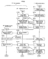
- FIG. 3 is a flowchart illustrating operations in which a device is recognized for each USB peripheral.
- the USB portable device before inserted in the host apparatus 2, initializes a mode thereof at an activating mode (S11).
- the activating mode the controlling USB peripheral 12c connected to the port "0" and the activating USB peripheral 12a connected to the port “1" are in the “ON” state.
- the storing USB peripheral 12b connected to the port "2" is in the "OFF” state.
- the USB host driver unit 21 detects the inserted USB portable device 1 (S12b). Upon the detection, the USB host driver unit 21 performs recognition (enumeration) of the detected USB portable device 1. More specifically, the USB host driver unit 21 inquires of the USB portable device 1 which device is available. In response to the inquiry, the USB portable device 1 notifies the USB host driver unit 21 that the activating USB peripheral 12a, which is in the "ON" state, is a readable device (S13c) and that the switching program 11 stored in the readable device is an auto-run (automatic execution) program.
- the USB host driver unit 21 Upon receiving the response, the USB host driver unit 21 recognizes the activating USB peripheral 12a as the readable device (S13b). The USB host driver unit 21 transmits, to the USB portable device 1, a transfer instruction to activate the recognized switching program 11 in the readable device as the automatic execution program (S14b). The USB portable device 1 transfers the switching program 11 to the host apparatus 2 (S14c). The host apparatus 2 starts execution of the switching program 11, which makes the switching program execution unit 22 operate.
- the switching program execution unit 22 transmits an instruction to unmount the readable device to the USB host driver unit 21 (S15a). Upon receiving the instruction, the USB host driver unit 21 unmount the readable device recognized in S13b (S15b). Note that the switching program 11 has already been transferred to the host apparatus 2 and executed as the switching program execution unit 22. Thus, the unmount does not interrupt the execution of the switching program 11.
- the switching program execution unit 22 gives the USB portable device 1 an instruction to switch modes thereof from the activating mode in S11 to the storing mode (S16a). Following the instruction, the USB portable device 1 switches the modes to the storing mode (S16c). In the storing mode, the controlling USB peripheral 12c connected to the port "0" and the storing USB peripheral 12b connected to the port “2" are in the “ON” state. The activating USB peripheral 12a connected to the port "1" is in the "OFF” state. Upon switching to the storing mode, the controller 15 of the controlling USB peripheral 12c gives the port switch 18b an instruction to change connections from the activating USB peripheral 12a to the storing USB peripheral 12b.
- the switching program execution unit 22 generates a detection event similar to an event generated when the USB portable device 1 is inserted into the USB port 29 (S12c) in order for the USB host driver unit 21 to recognize another device of the USB portable device 1 (S17a).
- the USB host driver unit 21 receives the detection event and detects the already-inserted USB portable device 1 once again (S17b, S17c). In response to the detection, the USB host driver unit 21 performs recognition (enumeration) of the detected USB portable device 1 for a second time.
- the USB host driver unit 21 inquires of the USB portable device 1 which device is available. In response to the inquiry, the USB portable device 1 notifies the USB host driver unit 21 that the storing USB peripheral 12b, which is in the "ON" state, is a readable and writable device (S18c). Upon receiving the response, the USB host driver unit 21 recognizes the storing USB peripheral 12b as the readable and writable device (S18b).
- the host apparatus 2 can read and write data in the storing USB peripheral 12b which has already been recognized. Meanwhile, the unmounted activating USB peripheral 12a is not at all visible from the USB host driver unit 21 at this time. This conveniently eliminates need for reading or writing data in the activating USB peripheral 12a.
- two areas, one which is readable in the activating USB peripheral 12a and the other which is readable and writable in the storing USB peripheral 12b can be efficiently used by switching over the two areas, while reducing fraudulent access to the activating USB peripheral 12a.
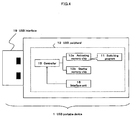
- FIG. 4 is a configuration diagram illustrating the USB portable device 1 in which a device is recognized for each memory chip.
- the USB portable device 1 includes a USB peripheral 12.
- the USB peripheral 12 includes memory chips (an activating memory chip 13a and a storing memory chip 13b); the controller 15 controlling a read and a write of data from and into the memory chips; and the interface unit 16 controlling the controller 15.
- the activating memory chip 13a corresponds to the activating storage unit 1a of FIG. 1B .
- the storing memory chip 13b corresponds to the storing storage unit 1b of FIG. 1B .
- the controller 15 connects either one of the activating memory chip 13a and the storing memory chip 13b, to the USB interface 19.
- the controller 15 thus sets each of the memory chips at either the "ON” state or the "OFF” state.
- the activating memory chip 13a and the storing memory chip 13b are alternately switchable between the "ON” state and the "OFF” state. If one of the memory chips 13a, 13b is in the "ON” state, the other is always in the "OFF state", and vice versa. In other words, it is not possible in this embodiment that both of the peripherals 12a, 12b are for example in the "ON” state at the same time.
- the activating memory chip 13a stores therein the switching program 11.
- the switching program 11 is to be automatically run.
- the interface unit 16 receives, from the switching program execution unit 22 via the USB interface 19, an instruction to designate one memory chip for being connected, from either the activating memory chip 13a or the storing memory chip 13b and operates the controller 15 according to the instruction.
- the interface unit 16 is recognized as a HID (Human Interface Device) class in USB standard by the USB host driver unit 21 so as to perform control communication with the host apparatus 2.
- HID Human Interface Device
- FIG. 5 is a flowchart illustrating operations in which a device is recognized for each memory chip.
- the USB portable device before inserted in the host apparatus 2, initializes a mode thereof at an activating mode (S11).
- the activating memory chip 13a In the activating mode, the activating memory chip 13a is in the "ON” state, and the storing memory chip 13b is in the "OFF" state.
- USB host driver unit 21 detects the inserted USB portable device 1 (S12b). Upon the detection, the USB host driver unit 21 performs recognition (enumeration) of the detected USB portable device 1. More specifically, the USB host driver unit 21 inquires of the USB portable device 1 which device is available. In response to the inquiry, the USB portable device 1 notifies the USB host driver unit 21 that the activating memory chip 13a, which is in the "ON" state, is a readable device (S23c) and that the switching program 11 stored in the readable device is an auto-run (automatic execution) program.
- the USB host driver unit 21 Upon receiving the response, the USB host driver unit 21 recognizes the activating memory chip 13a as the readable device (S23b). The USB host driver unit 21 transmits, to the USB portable device 1, a transfer instruction to activate the recognized switching program 11 in the readable device as the automatic execution program (S14b). The USB portable device 1 transfers the switching program 11 to the host apparatus 2 (S14c). The host apparatus 2 starts execution of the switching program 11, which makes the switching program execution unit 22 operate.
- the switching program execution unit 22 transmits an instruction to unmount the readable device to the USB host driver unit 21 (S15a). Upon receiving the instruction, the USB host driver unit 21 unmounts the readable device recognized in S23b (S15b). Note that the switching program 11 has already been transferred to the host apparatus 2 and executed as the switching program execution unit 22. Thus, the unmount does not interrupt the execution of the switching program 11.
- the switching program execution unit 22 gives the USB portable device 1 an instruction to switch modes thereof from the activating mode in S11 to the storing mode (S16a). Following the instruction, the USB portable device 1 switches the modes to the storing mode (S16c). In the storing mode, the storing memory chip 13b is in the "ON" state, and the activating memory chip 13a is in the "OFF" state. Upon switching to the storing mode, the controller 15 switches connections from the activating memory chip 13a to the storing memory chip 13b.
- the switching program execution unit 22 generates a detection event similar to an event inserted into the USB port 29 (S12c) in order for the USB host driver unit 21 to recognize another device of the USB portable device 1 (S17a).
- the USB host driver unit 21 receives the detection event and detects the already-inserted USB portable device 1 once again (S17b, S17c). In response to the detection, the USB host driver unit 21 performs recognition (enumeration) of the detected USB portable device 1 for a second time.
- the USB host driver unit 21 inquires of the USB portable device 1 which device is available. In response to the inquiry, the USB portable device 1 notifies the USB host driver unit 21 that the storing memory chip 13b, which is in the "ON" state, is a readable and writable device (S28c). Upon receiving the response, the USB host driver unit 21 recognizes the storing memory chip 13b as the readable and writable device (S28b).
- the host apparatus 2 can read and write data in the storing memory chip 13b which has already been recognized. Meanwhile, the unmounted activating memory chip 13a is not at all visible from the USB host driver unit 21 at this time. This conveniently eliminates need for reading or writing data in the activating USB peripheral 12a.
- two areas, one which is readable in the activating memory chip 13a and the other which is readable and writable in the storing memory chip 13b can be efficiently used by switching over the two areas, while reducing fraudulent access to the activating memory chip 13a.
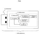
- FIG. 6 is a configuration diagram illustrating the USB portable device 1 in which a device is recognized for each virtual area.
- the USB portable device 1 includes the USB peripheral 12.
- the USB peripheral 12 includes a memory chip 13 in which a plurality of virtual areas are created (an activating virtual area 14a and a storing virtual area 14b); the controller 15 controlling a read and a write of data from and into the memory chip 13; and the interface unit 16 controlling the controller 15.
- the activating virtual area 14a corresponds to the activating storage unit 1a of FIG. 1B .
- the storing virtual area 14b corresponds to the storing storage unit 1b of FIG. 1B .
- the controller 15 connects either one of the activating virtual area 14a or the storing virtual area 14b, to the USB interface 19.
- the controller 15 thus sets each of the virtual areas at either the "ON” state or the "OFF” state.
- the activating virtual area 14a and the storing virtual area 14b are alternately switchable between the "ON” state and the "OFF” state. If one of the virtual areas 14a, 14b is in the "ON” state, the other is always in the "OFF state", and vice versa. In other words, it is not possible in this embodiment that both of the peripherals 12a, 12b are for example in the "ON” state at the same time.
- the activating virtual area 14a stores therein the switching program 11.
- the switching program 11 is to be automatically run.
- the interface unit 16 receives, from the switching program execution unit 22 via the USB interface 19, an instruction to designate one virtual area for being connected, from either the activating virtual area 14a or the storing virtual area 14b and operates the controller 15 according to the instruction.
- the interface unit 16 is recognized as, for example, a HID (Human Interface Device) class in USB standard by the USB host driver unit 21 so as to perform control communication with the host apparatus 2.
- HID Human Interface Device
- FIG. 7 is a flowchart illustrating operations in which a device is recognized for each virtual area.
- the USB portable device before inserted in the host apparatus 2, initializes a mode thereof at an activating mode (S11).
- the activating mode the activating virtual area 14a is in the "ON” state, and the storing virtual area 14b is in the "OFF" state.
- USB host driver unit 21 detects the inserted USB portable device 1 (S12b). Upon the detection, the USB host driver unit 21 performs recognition (enumeration) of the detected USB portable device 1. More specifically, the USB host driver unit 21 inquires of the USB portable device 1 which device is available. In response to the inquiry, the USB portable device 1 notifies the USB host driver unit 21 that the activating virtual area 14a, which is in the "ON" state, is a readable device (S33c) and that the switching program 11 stored in the readable device is an auto-run (automatic execution) program.
- the USB host driver unit 21 Upon receiving the response, the USB host driver unit 21 recognizes the activating virtual area 14a as the readable device (S33b). The USB host driver unit 21 transmits, to the USB portable device 1, a transfer instruction to activate the recognized switching program 11 in the readable device as the automatic execution program (S14b). The USB portable device 1 transfers the switching program 11 to the host apparatus 2 (S14c). The host apparatus 2 starts execution of the switching program 11, which makes the switching program execution unit 22 operate.
- the switching program execution unit 22 transmits an instruction to unmount the readable device to the USB host driver unit 21 (S15a). Upon receiving the instruction, the USB host driver unit 21 unmounts the readable device recognized in S23b (S15b). Note that the switching program 11 has already been transferred to the host apparatus 2 and executed as the switching program execution unit 22. Thus, the unmount does not interrupt the execution of the switching program 11.
- the switching program execution unit 22 gives the USB portable device 1 an instruction to switch modes thereof from the activating mode in S11 to the storing mode (S16a). Following the instruction, the USB portable device 1 switches the modes to the storing mode (S16c). In the storing mode, the storing virtual area 14b is in the "ON" state, and the activating virtual area 14a is in the "OFF" state. Upon switching to the storing mode, the controller 15 switches connections from the activating virtual area 14a to the storing virtual area 14b.
- the switching program execution unit 22 generates a detection event similar to an event generated when the USB portable device 1 is inserted into the USB port 29 (S12c) in order for the USB host driver unit 21 to recognize another device of the USB portable device 1 (S17a).
- the USB host driver unit 21 receives the detection event and detects the already-inserted USB portable device 1 once again (S17b, S17c). In response to the detection, the.USB host driver unit 21 performs recognition (enumeration) of the detected USB portable device 1 for a second time.
- the USB host driver unit 21 inquires of the USB portable device 1 which device is available. In response to the inquiry, the USB portable device 1 notifies the USB host driver unit 21 that the storing virtual area 14b, which is in the "ON" state, is a readable and writable device (S38c). Upon receiving the response, the USB host driver unit 21 recognizes the storing virtual area 14b as the readable and writable device (S38b).
- the host apparatus 2 can read and write data in the storing virtual area 14b which has already been recognized. Meanwhile, the unmounted activating virtual area 14a is not at all visible from the USB host driver unit 21 at this time. This conveniently eliminates need for reading or writing data in the activating USB peripheral 12a.
- two areas, one which is readable in the activating virtual area 14a and the other which is readable and writable in the storing virtual area 14b can be efficiently used by switching over the two areas, while reducing fraudulent access to the activating virtual area 14a.
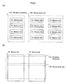
- FIG. 8(a) and FIG. 8(b) are explanatory.diagrams each illustrating that a virtual area is created using a plurality of memory chips. Compare FIG. 8(a) and FIG. 8(b) with FIG. 6 .
- the activating virtual area 14a and the storing virtual area 14b share one memory chip 13.
- the activating virtual area 14a and the storing virtual area 14b each have a plurality of dedicated memory chips 13.
- the activating virtual area 14a and the storing virtual area 14b share a plurality of memory chips 13.
- the activating virtual area 14a is configured to have four memory chips 13 by way of example. If the switching program 11 is thus redundantly stored in a plurality of the memory chips 13, the multiply-stored memory chips 13 can improve resistance against failure.
- the switching program 11 selects and switches to one storage unit to be recognized by the USB host driver unit 21 from among a plurality of storage units.
- a storage unit in the OFF state is thus invisible from the USB host driver unit 21. This eliminates need of constantly controlling a fraudulent access to a storage unit in the OFF state, otherwise, for example, by means of a control of excluding an unauthorized write instruction to a readable device. As a result, fraudulent access can be prevented and security is improved without causing performance deterioration accompanied by such a constant control.
- the first embodiment has a plurality of USB peripherals.
- the second embodiment has a plurality of memory chips.
- the third embodiment has a plurality of virtual areas.
- the third embodiment costs the least of the three because a virtual area does not require additional hardware.
- the second embodiment costs the second least because an additional USB peripheral is not necessary but an additional memory chip is necessary.
- the first embodiment costs the third because both an additional peripheral and an additional memory chip thereof are necessary.
- the first embodiment is the most reliable because a hardware failure of one USB peripheral does not affect the other USB peripherals.
- the second embodiment is the second most reliable because a hardware failure of one memory chip does not affect the other memory chips.
- the third embodiment is the third because a failure of one memory chip makes all virtual areas in the memory chip unusable.
- an activating storage unit is a possible target for a fraudulent write, to which a prevention measure is necessary.
- the activating storage can be recognized as a readable device by the USB host driver unit 21, though just during a very short period of time which is required for activating the switching program 11 (in FIG. 3 , a time period from S13b to S15b).
- a very short period of time which is required for activating the switching program 11 (in FIG. 3 , a time period from S13b to S15b).
- an access control can be performed such that, only during the very short time period, at least one of the USB portable device 1 and the host apparatus 2 ignores any write instruction to a readable device.
- the access control does generate performance deterioration, however, only during the very short time period. This will pose little problem for actual operations.
- the storage unit is configured to be a ROM (Read Only Memory) which has an attribute of being readable but unwritable. This ensures that the switching program 11 is prevented from being falsified, though making it impossible for the switching program 11 written in the ROM to be updated.
- ROM Read Only Memory
- the switching program 11 switches, as a basic function thereof, a storage unit to be recognized as described above.
- the switching program 11 can be configured to realize functions of various applications suitable for usage of the USB portable device 1.
- the switching program 11 is configured to authenticate a user of the USB portable device 1 with a password entry or the like as a requirement of switching a storage unit. This can prevent those other than the user of the USB portable device 1 from inappropriately looking at data in the USB portable device 1 even if somehow obtained.
- a path for controlling via the interface unit 16 and a path for data communication not via the interface unit 16 may be disposed separately. Or, the interface unit 16 may be omitted, and only the path for data communication may be used. In the latter case, both a communication packet for controlling and a communication packet for data communication are in one path. This requires information for distinguish one communication packet from the other.
- the two communication packets can be distinguished by, for example, setting a prescribed flag on a communication packet for controlling and not setting the prescribed flag on a communication packet for data communication.
- the controller 15 of the controlling USB peripheral 12c constantly monitors a communication packet communicated via the USB interface 19.
- the controller 15 receives a communication packet with the prescribed flag as the communication packet for controlling and transfers another communication packet without the prescribed flag to a USB peripheral which is connected to the port switch 18b and is in the "ON" state.
- the controller 15 constantly monitors a communication packet communicated via the USB interface 19.
- the controller 15 receives a communication packet with a prescribed flag as the communication packet for controlling.
- the controller 15 receives another communication packet without the prescribed flag as a communication packet for data communication.
- one or a plurality of the storing storage units 1b may be used as explained in the above embodiments. If a plurality of the storing storage units 1b are used, only one of those storing storage units 1b is recognized.
Landscapes
- Engineering & Computer Science (AREA)
- Theoretical Computer Science (AREA)
- Physics & Mathematics (AREA)
- General Engineering & Computer Science (AREA)
- General Physics & Mathematics (AREA)
- Information Transfer Systems (AREA)
Claims (6)
- Transportables USB-Gerät (1), das ein Schaltprogramm (11) speichert, das durch Anschließen an eine Hauptrechnervorrichtung (2) ausgeführt wird, Folgendes umfassend:eine aktivierende USB-Funktionseinheit (12a), die das Schaltprogramm (11) speichert,eine speichernde USB-Funktionseinheit (12b), die das Lesen und Schreiben von der Hauptrechnervorrichtung (2) ermöglicht, undeine steuernde USB-Funktionseinheit (12c), die ein Gerät schaltet, das durch die Hauptrechnervorrichtung (2) erkannt werden soll,dadurch gekennzeichnet, dass die steuernde USB-Funktionseinheit (12c):bewirkt, dass die Hauptrechnervorrichtung (2) die aktivierende USB-Funktionseinheit (12a) als ein lesbares Gerät erkennt, wenn das transportable USB-Gerät (1) an die Hauptrechnervorrichtung (2) angeschlossen ist,von der Hauptrechnervorrichtung (2) einen Schaltbefehl empfängt, der durch ein Ausführen des Schaltprogramms (11) in der Hauptrechnervorrichtung (2) gegeben wird, nachdem das Schaltprogramm (11) vom lesbaren Gerät zur Hauptrechnervorrichtung (2) übertragen wurde, undbewirkt, dass die Hauptrechnervorrichtung (2) das lesbare Gerät beendet, und bewirkt, dass die Hauptrechnervorrichtung (2) die speichernde USB-Funktionseinheit (12b) als ein lesbares und beschreibbares Gerät erkennt.
- Transportables USB-Gerät (1), das ein Schaltprogramm (11) speichert, das durch Anschließen an eine Hauptrechnervorrichtung (2) ausgeführt wird, Folgendes umfassend:einen aktivierenden Speicherchip (13), der das Schaltprogramm (11) speichert,einen speichernden Speicherchip (13), der das Lesen und Schreiben von der Hauptrechnervorrichtung (2) ermöglicht, undeinen Controller (15), der ein Gerät schaltet, das durch die Hauptrechnervorrichtung erkannt werden soll,dadurch gekennzeichnet, dass der Controller (15):bewirkt, dass die Hauptrechnervorrichtung (2) den aktivierenden Speicherchip (13) als ein lesbares Gerät erkennt, wenn das transportable USB-Gerät (1) an die Hauptrechnervorrichtung (2) angeschlossen ist,von der Hauptrechnervorrichtung (2) einen Schaltbefehl empfängt, der durch ein Ausführen des Schaltprogramms (11) in der Hauptrechnervorrichtung (2) gegeben wird, nachdem das Schaltprogramm (11) vom lesbaren Gerät zur Hauptrechnervorrichtung (2) übertragen wurde, undbewirkt, dass die Hauptrechnervorrichtung (2) das lesbare Gerät beendet, und bewirkt, dass die Hauptrechnervorrichtung (2) den speichernden Speicherchip (13) als ein lesbares und beschreibbares Gerät erkennt.
- Transportables USB-Gerät (1), das ein Schaltprogramm (11) speichert, das durch Anschließen an eine Hauptrechnervorrichtung (2) ausgeführt wird, Folgendes umfassend:einen aktivierenden virtuellen Bereich (14a), der das Schaltprogramm (11) speichert,einen speichernden virtuellen Bereich (14b), der das Lesen und Schreiben von der Hauptrechnervorrichtung (2) ermöglicht, undeinen Controller (15), der ein Gerät schaltet, das durch die Hauptrechnervorrichtung (2) erkannt werden soll,wobei der aktivierende virtuelle Bereich (14a) und der speichernde virtuelle Bereich (14b) auf einem oder mehreren Speicherchips (13) erzeugt sind,dadurch gekennzeichnet, dass der Controller (15):bewirkt, dass die Hauptrechnervorrichtung (2) den aktivierenden virtuellen Bereich (14a) als ein lesbares Gerät erkennt, wenn das transportable USB-Gerät (1) an die Hauptrechnervorrichtung (2) angeschlossen ist,von der Hauptrechnervorrichtung (2) einen Schaltbefehl empfängt, der durch ein Ausführen des Schaltprogramms (11) in der Hauptrechnervorrichtung (2) gegeben wird, nachdem das Schaltprogramm (11) vom lesbaren Gerät zur Hauptrechnervorrichtung (2) übertragen wurde, undbewirkt, dass die Hauptrechnervorrichtung (2) das lesbare Gerät beendet, und bewirkt, dass die Hauptrechnervorrichtung (2) den speichernden virtuellen Bereich (14b) als ein lesbares und beschreibbares Gerät erkennt.
- Transportables USB-Gerät (1) nach einem der Ansprüche 1 bis 3,
wobei das transportable USB-Gerät (1) eine Zugangssteuerung ausführt, bei der während einer Zeitspanne vom Erkennen des lesbaren Gerätes durch die Hauptrechnervorrichtung (2) bis zum Beenden des lesbaren Gerätes ein Schreibbefehl in das lesbare Gerät missachtet wird. - Transportables USB-Gerät (1) nach einem der Ansprüche 1 bis 4,
wobei das transportable USB-Gerät (1) bewirkt, dass die Hauptrechnervorrichtung (2) ein Speichermedium, das physisch nicht beschreibbar ist, als lesbares Gerät erkennt. - Transportables USB-Gerät (1) nach einem der Ansprüche 1 bis 5,
wobei das Schaltprogramm (11), das durch die Hauptrechnervorrichtung (2) ausgeführt wird, die Hauptrechnervorrichtung (2) dafür steuert, den Schaltbefehl nur dann zu übertragen, wenn ein festgelegter Benutzer des transportablen USB-Geräts (1) authentifiziert ist.
Applications Claiming Priority (1)
| Application Number | Priority Date | Filing Date | Title |
|---|---|---|---|
| PCT/JP2008/050415 WO2009090734A1 (ja) | 2008-01-16 | 2008-01-16 | Usb可搬装置 |
Publications (3)
| Publication Number | Publication Date |
|---|---|
| EP2246778A1 EP2246778A1 (de) | 2010-11-03 |
| EP2246778A4 EP2246778A4 (de) | 2012-01-11 |
| EP2246778B1 true EP2246778B1 (de) | 2013-04-24 |
Family
ID=40885145
Family Applications (1)
| Application Number | Title | Priority Date | Filing Date |
|---|---|---|---|
| EP08703276.9A Not-in-force EP2246778B1 (de) | 2008-01-16 | 2008-01-16 | Tragbare usb-vorrichtung |
Country Status (4)
| Country | Link |
|---|---|
| US (1) | US8527680B2 (de) |
| EP (1) | EP2246778B1 (de) |
| JP (1) | JP5216024B2 (de) |
| WO (1) | WO2009090734A1 (de) |
Families Citing this family (13)
| Publication number | Priority date | Publication date | Assignee | Title |
|---|---|---|---|---|
| KR20120037913A (ko) | 2009-07-28 | 2012-04-20 | 니폰 조키 세야쿠 가부시키가이샤 | 티아벤조아줄렌프로피온산 유도체의 제조법 |
| KR101748318B1 (ko) * | 2010-11-22 | 2017-06-27 | 삼성전자 주식회사 | 휴대 단말기의 어플리케이션 실행 방법 및 장치 |
| TWI533134B (zh) * | 2010-12-28 | 2016-05-11 | 慧榮科技股份有限公司 | 快閃記憶裝置及其運作方法 |
| US9307317B2 (en) | 2014-08-29 | 2016-04-05 | Coban Technologies, Inc. | Wireless programmable microphone apparatus and system for integrated surveillance system devices |
| WO2016033523A1 (en) * | 2014-08-29 | 2016-03-03 | Coban Technologies, Inc. | Compact multi-function dvr with multiple integrated wireless data communication devices |
| US10165171B2 (en) | 2016-01-22 | 2018-12-25 | Coban Technologies, Inc. | Systems, apparatuses, and methods for controlling audiovisual apparatuses |
| US10789840B2 (en) | 2016-05-09 | 2020-09-29 | Coban Technologies, Inc. | Systems, apparatuses and methods for detecting driving behavior and triggering actions based on detected driving behavior |
| US10152858B2 (en) | 2016-05-09 | 2018-12-11 | Coban Technologies, Inc. | Systems, apparatuses and methods for triggering actions based on data capture and characterization |
| US10370102B2 (en) | 2016-05-09 | 2019-08-06 | Coban Technologies, Inc. | Systems, apparatuses and methods for unmanned aerial vehicle |
| US11936645B2 (en) * | 2017-03-30 | 2024-03-19 | Kingston Digital, Inc. | Smart security storage system |
| US10880296B2 (en) | 2017-03-30 | 2020-12-29 | Kingston Digital Inc. | Smart security storage |
| US10169567B1 (en) * | 2017-11-21 | 2019-01-01 | Lockheed Martin Corporation | Behavioral authentication of universal serial bus (USB) devices |
| CN109033848B (zh) * | 2018-06-25 | 2020-09-25 | 湖南国科微电子股份有限公司 | 存储数据安全运行方法及系统 |
Family Cites Families (19)
| Publication number | Priority date | Publication date | Assignee | Title |
|---|---|---|---|---|
| JPH07234759A (ja) | 1994-02-22 | 1995-09-05 | Nikon Corp | 記憶装置 |
| JPH10289159A (ja) | 1997-04-17 | 1998-10-27 | Matsushita Electric Ind Co Ltd | アクセス制御装置 |
| JP4391615B2 (ja) * | 1999-03-04 | 2009-12-24 | インターナショナル・ビジネス・マシーンズ・コーポレーション | 非接触データ・キャリア・システムにおける不正アクセス防止方法 |
| PL355475A1 (en) * | 2000-02-21 | 2004-05-04 | Trek 2000 International Ltd. | A portable data storage device |
| JP3954271B2 (ja) * | 2000-03-16 | 2007-08-08 | 本田技研工業株式会社 | 車両制御装置のためのメモリ書き換えシステム |
| JP2002245787A (ja) | 2001-02-14 | 2002-08-30 | Sharp Corp | 半導体記憶装置 |
| JP2003085042A (ja) | 2001-09-13 | 2003-03-20 | Seiko Instruments Inc | コンピュータのセキュリティシステム |
| JP2003178017A (ja) | 2001-09-17 | 2003-06-27 | Anyone Kk | プログラム内蔵のusbデバイス |
| JP3767818B2 (ja) * | 2002-10-28 | 2006-04-19 | 株式会社サスライト | 着脱式デバイス及びプログラムの起動方法 |
| JP4245374B2 (ja) * | 2002-11-01 | 2009-03-25 | 株式会社サスライト | 着脱式デバイスおよび制御回路 |
| US7478248B2 (en) * | 2002-11-27 | 2009-01-13 | M-Systems Flash Disk Pioneers, Ltd. | Apparatus and method for securing data on a portable storage device |
| WO2004086363A2 (en) | 2003-03-27 | 2004-10-07 | M-Systems Flash Disk Pioneers Ltd. | Data storage device with full access by all users |
| CN100383756C (zh) * | 2003-07-22 | 2008-04-23 | 深圳市朗科科技有限公司 | 利用半导体存储装置实现自动执行的方法 |
| JP2005115636A (ja) | 2003-10-07 | 2005-04-28 | Ankoku Kokusai Kagi Kofun Yugenkoshi | 携帯式情報記憶装置及び当該装置の磁気ディスク形式の動的設定方法 |
| US7392358B2 (en) * | 2005-01-14 | 2008-06-24 | Sandisk Corporation | Delivery of a message to a user of a portable data storage device as a condition of its use |
| US7721115B2 (en) * | 2005-02-16 | 2010-05-18 | Cypress Semiconductor Corporation | USB secure storage apparatus and method |
| US8528096B2 (en) * | 2005-10-07 | 2013-09-03 | Stmicroelectronics, Inc. | Secure universal serial bus (USB) storage device and method |
| JP2007148644A (ja) | 2005-11-25 | 2007-06-14 | Sharp Corp | データ記憶装置、icカード及びデータ記憶方法 |
| JP4799239B2 (ja) | 2006-03-29 | 2011-10-26 | 株式会社日立ソリューションズ | 情報漏洩防止方法及びリムーバブルメディア |
-
2008
- 2008-01-16 JP JP2009549925A patent/JP5216024B2/ja active Active
- 2008-01-16 EP EP08703276.9A patent/EP2246778B1/de not_active Not-in-force
- 2008-01-16 US US12/863,233 patent/US8527680B2/en not_active Expired - Fee Related
- 2008-01-16 WO PCT/JP2008/050415 patent/WO2009090734A1/ja not_active Ceased
Also Published As
| Publication number | Publication date |
|---|---|
| US8527680B2 (en) | 2013-09-03 |
| WO2009090734A1 (ja) | 2009-07-23 |
| EP2246778A1 (de) | 2010-11-03 |
| US20110016256A1 (en) | 2011-01-20 |
| EP2246778A4 (de) | 2012-01-11 |
| JPWO2009090734A1 (ja) | 2011-05-26 |
| JP5216024B2 (ja) | 2013-06-19 |
Similar Documents
| Publication | Publication Date | Title |
|---|---|---|
| EP2246778B1 (de) | Tragbare usb-vorrichtung | |
| US8255930B2 (en) | Method and system for dynamically switching between different device configurations | |
| CN1795439B (zh) | 计算机操作系统的安全系统与方法 | |
| CN107885679B (zh) | 一种可实现自动运行的集成电路存储设备或方法 | |
| US7478191B2 (en) | Method for automatically switching USB peripherals between USB hosts | |
| EP1342145B1 (de) | Schreibschutz für langfristige computerspeichergeräte | |
| CN100452003C (zh) | 多接口和可自动安装的信息安全设备及其控制方法 | |
| US20100191873A1 (en) | Enabling and disabling device images on a platform without disrupting bios or os | |
| CN101620541A (zh) | 信息处理设备及其启动方法 | |
| CN100401280C (zh) | 通用串行总线数据传输方法 | |
| US9032540B2 (en) | Access system and method thereof | |
| US20050034125A1 (en) | Multiple virtual devices | |
| KR101235851B1 (ko) | 시스템 관리 봉쇄를 극복하기 위한 방법 | |
| US6970954B1 (en) | System and method for intercepting and evaluating commands to determine if commands are harmful or benign and to emulate harmful commands | |
| US20090019211A1 (en) | Establishing A Redundant Array Of Inexpensive Drives | |
| US20140372653A1 (en) | Storage Device with Multiple Interfaces and Multiple Levels of Data Protection and Related Method Thereof | |
| US5937157A (en) | Information processing apparatus and a control method | |
| US20070233727A1 (en) | Multiple Virtual Devices | |
| US20080059740A1 (en) | Hardware for manually enabling and disabling read and write protection to parts of a storage disk or disks for users | |
| WO2010114523A1 (en) | Bios usb write prevent | |
| JP3100958B2 (ja) | ポータブルコンピュータ | |
| US20170131926A1 (en) | System, electronic apparatus and method | |
| US20150348651A1 (en) | Multiple access test architecture for memory storage devices | |
| CN106909311A (zh) | 数据储存装置及其储存方法 | |
| JP2022021473A (ja) | 情報処理装置、情報処理装置の制御方法、情報処理システム及びプログラム |
Legal Events
| Date | Code | Title | Description |
|---|---|---|---|
| PUAI | Public reference made under article 153(3) epc to a published international application that has entered the european phase |
Free format text: ORIGINAL CODE: 0009012 |
|
| 17P | Request for examination filed |
Effective date: 20100730 |
|
| AK | Designated contracting states |
Kind code of ref document: A1 Designated state(s): AT BE BG CH CY CZ DE DK EE ES FI FR GB GR HR HU IE IS IT LI LT LU LV MC MT NL NO PL PT RO SE SI SK TR |
|
| AX | Request for extension of the european patent |
Extension state: AL BA MK RS |
|
| DAX | Request for extension of the european patent (deleted) | ||
| A4 | Supplementary search report drawn up and despatched |
Effective date: 20111214 |
|
| RIC1 | Information provided on ipc code assigned before grant |
Ipc: G06F 3/06 20060101AFI20111208BHEP Ipc: G06F 13/38 20060101ALI20111208BHEP Ipc: G06F 13/10 20060101ALI20111208BHEP |
|
| RIC1 | Information provided on ipc code assigned before grant |
Ipc: G06F 13/38 20060101ALI20120927BHEP Ipc: G06F 3/06 20060101AFI20120927BHEP Ipc: G06F 13/10 20060101ALI20120927BHEP |
|
| GRAP | Despatch of communication of intention to grant a patent |
Free format text: ORIGINAL CODE: EPIDOSNIGR1 |
|
| GRAS | Grant fee paid |
Free format text: ORIGINAL CODE: EPIDOSNIGR3 |
|
| RIN1 | Information on inventor provided before grant (corrected) |
Inventor name: HATADA, MASAHIRO |
|
| GRAA | (expected) grant |
Free format text: ORIGINAL CODE: 0009210 |
|
| RAP1 | Party data changed (applicant data changed or rights of an application transferred) |
Owner name: I-O DATA DEVICE, INC. |
|
| AK | Designated contracting states |
Kind code of ref document: B1 Designated state(s): AT BE BG CH CY CZ DE DK EE ES FI FR GB GR HR HU IE IS IT LI LT LU LV MC MT NL NO PL PT RO SE SI SK TR |
|
| REG | Reference to a national code |
Ref country code: GB Ref legal event code: FG4D |
|
| REG | Reference to a national code |
Ref country code: CH Ref legal event code: EP |
|
| REG | Reference to a national code |
Ref country code: AT Ref legal event code: REF Ref document number: 608967 Country of ref document: AT Kind code of ref document: T Effective date: 20130515 |
|
| REG | Reference to a national code |
Ref country code: IE Ref legal event code: FG4D |
|
| REG | Reference to a national code |
Ref country code: DE Ref legal event code: R096 Ref document number: 602008024051 Country of ref document: DE Effective date: 20130620 |
|
| REG | Reference to a national code |
Ref country code: AT Ref legal event code: MK05 Ref document number: 608967 Country of ref document: AT Kind code of ref document: T Effective date: 20130424 |
|
| REG | Reference to a national code |
Ref country code: LT Ref legal event code: MG4D |
|
| REG | Reference to a national code |
Ref country code: NL Ref legal event code: VDEP Effective date: 20130424 |
|
| PG25 | Lapsed in a contracting state [announced via postgrant information from national office to epo] |
Ref country code: ES Free format text: LAPSE BECAUSE OF FAILURE TO SUBMIT A TRANSLATION OF THE DESCRIPTION OR TO PAY THE FEE WITHIN THE PRESCRIBED TIME-LIMIT Effective date: 20130804 Ref country code: AT Free format text: LAPSE BECAUSE OF FAILURE TO SUBMIT A TRANSLATION OF THE DESCRIPTION OR TO PAY THE FEE WITHIN THE PRESCRIBED TIME-LIMIT Effective date: 20130424 Ref country code: NO Free format text: LAPSE BECAUSE OF FAILURE TO SUBMIT A TRANSLATION OF THE DESCRIPTION OR TO PAY THE FEE WITHIN THE PRESCRIBED TIME-LIMIT Effective date: 20130724 Ref country code: BE Free format text: LAPSE BECAUSE OF FAILURE TO SUBMIT A TRANSLATION OF THE DESCRIPTION OR TO PAY THE FEE WITHIN THE PRESCRIBED TIME-LIMIT Effective date: 20130424 Ref country code: GR Free format text: LAPSE BECAUSE OF FAILURE TO SUBMIT A TRANSLATION OF THE DESCRIPTION OR TO PAY THE FEE WITHIN THE PRESCRIBED TIME-LIMIT Effective date: 20130725 Ref country code: SI Free format text: LAPSE BECAUSE OF FAILURE TO SUBMIT A TRANSLATION OF THE DESCRIPTION OR TO PAY THE FEE WITHIN THE PRESCRIBED TIME-LIMIT Effective date: 20130424 Ref country code: PT Free format text: LAPSE BECAUSE OF FAILURE TO SUBMIT A TRANSLATION OF THE DESCRIPTION OR TO PAY THE FEE WITHIN THE PRESCRIBED TIME-LIMIT Effective date: 20130826 Ref country code: LT Free format text: LAPSE BECAUSE OF FAILURE TO SUBMIT A TRANSLATION OF THE DESCRIPTION OR TO PAY THE FEE WITHIN THE PRESCRIBED TIME-LIMIT Effective date: 20130424 Ref country code: FI Free format text: LAPSE BECAUSE OF FAILURE TO SUBMIT A TRANSLATION OF THE DESCRIPTION OR TO PAY THE FEE WITHIN THE PRESCRIBED TIME-LIMIT Effective date: 20130424 Ref country code: SE Free format text: LAPSE BECAUSE OF FAILURE TO SUBMIT A TRANSLATION OF THE DESCRIPTION OR TO PAY THE FEE WITHIN THE PRESCRIBED TIME-LIMIT Effective date: 20130424 Ref country code: IS Free format text: LAPSE BECAUSE OF FAILURE TO SUBMIT A TRANSLATION OF THE DESCRIPTION OR TO PAY THE FEE WITHIN THE PRESCRIBED TIME-LIMIT Effective date: 20130824 |
|
| PG25 | Lapsed in a contracting state [announced via postgrant information from national office to epo] |
Ref country code: CY Free format text: LAPSE BECAUSE OF FAILURE TO SUBMIT A TRANSLATION OF THE DESCRIPTION OR TO PAY THE FEE WITHIN THE PRESCRIBED TIME-LIMIT Effective date: 20130424 Ref country code: LV Free format text: LAPSE BECAUSE OF FAILURE TO SUBMIT A TRANSLATION OF THE DESCRIPTION OR TO PAY THE FEE WITHIN THE PRESCRIBED TIME-LIMIT Effective date: 20130424 Ref country code: HR Free format text: LAPSE BECAUSE OF FAILURE TO SUBMIT A TRANSLATION OF THE DESCRIPTION OR TO PAY THE FEE WITHIN THE PRESCRIBED TIME-LIMIT Effective date: 20130424 Ref country code: BG Free format text: LAPSE BECAUSE OF FAILURE TO SUBMIT A TRANSLATION OF THE DESCRIPTION OR TO PAY THE FEE WITHIN THE PRESCRIBED TIME-LIMIT Effective date: 20130724 Ref country code: PL Free format text: LAPSE BECAUSE OF FAILURE TO SUBMIT A TRANSLATION OF THE DESCRIPTION OR TO PAY THE FEE WITHIN THE PRESCRIBED TIME-LIMIT Effective date: 20130424 |
|
| PG25 | Lapsed in a contracting state [announced via postgrant information from national office to epo] |
Ref country code: DK Free format text: LAPSE BECAUSE OF FAILURE TO SUBMIT A TRANSLATION OF THE DESCRIPTION OR TO PAY THE FEE WITHIN THE PRESCRIBED TIME-LIMIT Effective date: 20130424 Ref country code: CZ Free format text: LAPSE BECAUSE OF FAILURE TO SUBMIT A TRANSLATION OF THE DESCRIPTION OR TO PAY THE FEE WITHIN THE PRESCRIBED TIME-LIMIT Effective date: 20130424 Ref country code: EE Free format text: LAPSE BECAUSE OF FAILURE TO SUBMIT A TRANSLATION OF THE DESCRIPTION OR TO PAY THE FEE WITHIN THE PRESCRIBED TIME-LIMIT Effective date: 20130424 Ref country code: SK Free format text: LAPSE BECAUSE OF FAILURE TO SUBMIT A TRANSLATION OF THE DESCRIPTION OR TO PAY THE FEE WITHIN THE PRESCRIBED TIME-LIMIT Effective date: 20130424 |
|
| PG25 | Lapsed in a contracting state [announced via postgrant information from national office to epo] |
Ref country code: IT Free format text: LAPSE BECAUSE OF FAILURE TO SUBMIT A TRANSLATION OF THE DESCRIPTION OR TO PAY THE FEE WITHIN THE PRESCRIBED TIME-LIMIT Effective date: 20130424 Ref country code: RO Free format text: LAPSE BECAUSE OF FAILURE TO SUBMIT A TRANSLATION OF THE DESCRIPTION OR TO PAY THE FEE WITHIN THE PRESCRIBED TIME-LIMIT Effective date: 20130424 Ref country code: NL Free format text: LAPSE BECAUSE OF FAILURE TO SUBMIT A TRANSLATION OF THE DESCRIPTION OR TO PAY THE FEE WITHIN THE PRESCRIBED TIME-LIMIT Effective date: 20130424 |
|
| PLBE | No opposition filed within time limit |
Free format text: ORIGINAL CODE: 0009261 |
|
| STAA | Information on the status of an ep patent application or granted ep patent |
Free format text: STATUS: NO OPPOSITION FILED WITHIN TIME LIMIT |
|
| 26N | No opposition filed |
Effective date: 20140127 |
|
| REG | Reference to a national code |
Ref country code: DE Ref legal event code: R097 Ref document number: 602008024051 Country of ref document: DE Effective date: 20140127 |
|
| PG25 | Lapsed in a contracting state [announced via postgrant information from national office to epo] |
Ref country code: LU Free format text: LAPSE BECAUSE OF FAILURE TO SUBMIT A TRANSLATION OF THE DESCRIPTION OR TO PAY THE FEE WITHIN THE PRESCRIBED TIME-LIMIT Effective date: 20140116 Ref country code: MC Free format text: LAPSE BECAUSE OF FAILURE TO SUBMIT A TRANSLATION OF THE DESCRIPTION OR TO PAY THE FEE WITHIN THE PRESCRIBED TIME-LIMIT Effective date: 20130424 |
|
| REG | Reference to a national code |
Ref country code: CH Ref legal event code: PL |
|
| PG25 | Lapsed in a contracting state [announced via postgrant information from national office to epo] |
Ref country code: LI Free format text: LAPSE BECAUSE OF NON-PAYMENT OF DUE FEES Effective date: 20140131 Ref country code: CH Free format text: LAPSE BECAUSE OF NON-PAYMENT OF DUE FEES Effective date: 20140131 |
|
| REG | Reference to a national code |
Ref country code: IE Ref legal event code: MM4A |
|
| PG25 | Lapsed in a contracting state [announced via postgrant information from national office to epo] |
Ref country code: IE Free format text: LAPSE BECAUSE OF NON-PAYMENT OF DUE FEES Effective date: 20140116 |
|
| REG | Reference to a national code |
Ref country code: FR Ref legal event code: PLFP Year of fee payment: 9 |
|
| PG25 | Lapsed in a contracting state [announced via postgrant information from national office to epo] |
Ref country code: MT Free format text: LAPSE BECAUSE OF FAILURE TO SUBMIT A TRANSLATION OF THE DESCRIPTION OR TO PAY THE FEE WITHIN THE PRESCRIBED TIME-LIMIT Effective date: 20130424 |
|
| PG25 | Lapsed in a contracting state [announced via postgrant information from national office to epo] |
Ref country code: HU Free format text: LAPSE BECAUSE OF FAILURE TO SUBMIT A TRANSLATION OF THE DESCRIPTION OR TO PAY THE FEE WITHIN THE PRESCRIBED TIME-LIMIT; INVALID AB INITIO Effective date: 20080116 Ref country code: TR Free format text: LAPSE BECAUSE OF FAILURE TO SUBMIT A TRANSLATION OF THE DESCRIPTION OR TO PAY THE FEE WITHIN THE PRESCRIBED TIME-LIMIT Effective date: 20130424 |
|
| REG | Reference to a national code |
Ref country code: FR Ref legal event code: PLFP Year of fee payment: 10 |
|
| REG | Reference to a national code |
Ref country code: FR Ref legal event code: PLFP Year of fee payment: 11 |
|
| REG | Reference to a national code |
Ref country code: DE Ref legal event code: R082 Ref document number: 602008024051 Country of ref document: DE |
|
| PGFP | Annual fee paid to national office [announced via postgrant information from national office to epo] |
Ref country code: GB Payment date: 20211206 Year of fee payment: 15 Ref country code: FR Payment date: 20211217 Year of fee payment: 15 |
|
| PGFP | Annual fee paid to national office [announced via postgrant information from national office to epo] |
Ref country code: DE Payment date: 20211130 Year of fee payment: 15 |
|
| REG | Reference to a national code |
Ref country code: DE Ref legal event code: R119 Ref document number: 602008024051 Country of ref document: DE |
|
| GBPC | Gb: european patent ceased through non-payment of renewal fee |
Effective date: 20230116 |
|
| PG25 | Lapsed in a contracting state [announced via postgrant information from national office to epo] |
Ref country code: GB Free format text: LAPSE BECAUSE OF NON-PAYMENT OF DUE FEES Effective date: 20230116 Ref country code: DE Free format text: LAPSE BECAUSE OF NON-PAYMENT OF DUE FEES Effective date: 20230801 |
|
| PG25 | Lapsed in a contracting state [announced via postgrant information from national office to epo] |
Ref country code: FR Free format text: LAPSE BECAUSE OF NON-PAYMENT OF DUE FEES Effective date: 20230131 |