EP2246526B1 - Rotor, turbinenscheibe und gasturbine - Google Patents
Rotor, turbinenscheibe und gasturbine Download PDFInfo
- Publication number
- EP2246526B1 EP2246526B1 EP09715480.1A EP09715480A EP2246526B1 EP 2246526 B1 EP2246526 B1 EP 2246526B1 EP 09715480 A EP09715480 A EP 09715480A EP 2246526 B1 EP2246526 B1 EP 2246526B1
- Authority
- EP
- European Patent Office
- Prior art keywords
- cooling holes
- turbine
- rotor
- cooling
- turbine disk
- Prior art date
- Legal status (The legal status is an assumption and is not a legal conclusion. Google has not performed a legal analysis and makes no representation as to the accuracy of the status listed.)
- Active
Links
- 238000001816 cooling Methods 0.000 claims description 163
- 239000007789 gas Substances 0.000 claims description 24
- 239000000112 cooling gas Substances 0.000 claims description 11
- 239000000567 combustion gas Substances 0.000 claims description 10
- 239000000446 fuel Substances 0.000 claims description 6
- 238000007789 sealing Methods 0.000 claims description 4
- 238000002485 combustion reaction Methods 0.000 description 4
- 230000000149 penetrating effect Effects 0.000 description 3
- 239000002826 coolant Substances 0.000 description 2
- 230000003068 static effect Effects 0.000 description 2
- 238000011144 upstream manufacturing Methods 0.000 description 2
- 238000005452 bending Methods 0.000 description 1
- 230000000740 bleeding effect Effects 0.000 description 1
- 239000012141 concentrate Substances 0.000 description 1
- 230000000694 effects Effects 0.000 description 1
- 239000012530 fluid Substances 0.000 description 1
- 239000002737 fuel gas Substances 0.000 description 1
- 239000000463 material Substances 0.000 description 1
- 230000002093 peripheral effect Effects 0.000 description 1
Images


Classifications
-
- F—MECHANICAL ENGINEERING; LIGHTING; HEATING; WEAPONS; BLASTING
- F01—MACHINES OR ENGINES IN GENERAL; ENGINE PLANTS IN GENERAL; STEAM ENGINES
- F01D—NON-POSITIVE DISPLACEMENT MACHINES OR ENGINES, e.g. STEAM TURBINES
- F01D5/00—Blades; Blade-carrying members; Heating, heat-insulating, cooling or antivibration means on the blades or the members
- F01D5/02—Blade-carrying members, e.g. rotors
- F01D5/08—Heating, heat-insulating or cooling means
- F01D5/085—Heating, heat-insulating or cooling means cooling fluid circulating inside the rotor
- F01D5/087—Heating, heat-insulating or cooling means cooling fluid circulating inside the rotor in the radial passages of the rotor disc
-
- F—MECHANICAL ENGINEERING; LIGHTING; HEATING; WEAPONS; BLASTING
- F01—MACHINES OR ENGINES IN GENERAL; ENGINE PLANTS IN GENERAL; STEAM ENGINES
- F01D—NON-POSITIVE DISPLACEMENT MACHINES OR ENGINES, e.g. STEAM TURBINES
- F01D5/00—Blades; Blade-carrying members; Heating, heat-insulating, cooling or antivibration means on the blades or the members
- F01D5/02—Blade-carrying members, e.g. rotors
- F01D5/08—Heating, heat-insulating or cooling means
- F01D5/081—Cooling fluid being directed on the side of the rotor disc or at the roots of the blades
-
- F—MECHANICAL ENGINEERING; LIGHTING; HEATING; WEAPONS; BLASTING
- F01—MACHINES OR ENGINES IN GENERAL; ENGINE PLANTS IN GENERAL; STEAM ENGINES
- F01D—NON-POSITIVE DISPLACEMENT MACHINES OR ENGINES, e.g. STEAM TURBINES
- F01D5/00—Blades; Blade-carrying members; Heating, heat-insulating, cooling or antivibration means on the blades or the members
- F01D5/30—Fixing blades to rotors; Blade roots ; Blade spacers
- F01D5/32—Locking, e.g. by final locking blades or keys
- F01D5/323—Locking of axial insertion type blades by means of a key or the like parallel to the axis of the rotor
-
- F—MECHANICAL ENGINEERING; LIGHTING; HEATING; WEAPONS; BLASTING
- F05—INDEXING SCHEMES RELATING TO ENGINES OR PUMPS IN VARIOUS SUBCLASSES OF CLASSES F01-F04
- F05D—INDEXING SCHEME FOR ASPECTS RELATING TO NON-POSITIVE-DISPLACEMENT MACHINES OR ENGINES, GAS-TURBINES OR JET-PROPULSION PLANTS
- F05D2260/00—Function
- F05D2260/94—Functionality given by mechanical stress related aspects such as low cycle fatigue [LCF] of high cycle fatigue [HCF]
- F05D2260/941—Functionality given by mechanical stress related aspects such as low cycle fatigue [LCF] of high cycle fatigue [HCF] particularly aimed at mechanical or thermal stress reduction
Definitions
- the present invention relates to a rotor that is intended to be rotatably supported and has a turbine disk and a plurality of rotor blades on an outer circumference thereof in a gas turbine in which, for example, fuel is supplied to compressed high temperature and high pressure air for combustion, and combustion gas thus generated is supplied to a turbine to obtain drive power for rotation, and to a gas turbine having such a turbine disk.
- a gas turbine includes a compressor, a combustor, and a turbine. Air collected from an air inlet is compressed in the compressor to be turned into high temperature and high pressure compressed air. Fuel is supplied to the compressed air for combustion in the combustor. The high temperature and high pressure combustion gas drives the turbine, further to drive a generator that is connected to the turbine.
- the turbine includes a plurality of nozzles and rotor blades arranged in an alternating manner within a casing, and the rotor blades are driven by the combustion gas to drive an output shaft that is connected to the generator in rotation.
- the combustion gas that has driven the turbine is converted to a static pressure by way of a diffuser included in an exhaust casing, and then released into the air.
- a gas turbine has come to be demanded to be highly efficient and have a high output, and there is a tendency that the temperature of the combustion gas guided to the nozzles and the rotor blades is increased more than ever. Therefore, generally, a cooling passage is formed inside the nozzles and the rotor blades, and a cooling medium, such as air or steam, is allowed to flow in the cooling passage to cool the nozzles and the rotor blades, to ensure the heat resistance as well as to enable an increase in the temperature of the combustion gas so that the output and the efficiency are improved.
- a cooling medium such as air or steam
- a plurality of rotor blade bodies each having a cooling passage formed inside is arranged along and fixed to an outer circumference of the turbine disk in a circumferential direction. Cooling holes are formed on the turbine disk in a radial direction, and leading ends of the cooling holes are connected to the cooling passages in the rotor blade bodies.
- the cooling medium is supplied into the cooling holes from the base ends thereof, and flows inside the cooling passage via the cooling holes to cool the rotor blade bodies.
- Such a turbine cooling structure is disclosed in JP H8-218804 A , for example.
- US 6022190 A discloses the features of the preamble portion of claim 1, i.e. a rotor with a plurality of rotor blades arranged in a respective plurality of fitting grooves on a circumference of the turbine disk and at least two cooling holes are opened to penetrate the turbine disk from an inside toward the outside and to directly connect to the bottom of each fitting groove.
- JP 2031355 U discloses a rotor supporting a plurality of rotor blades in a turbine disk where a plurality of cooling holes are provided that penetrate the turbine disk from the inside toward the outside and are connected to the cooling passage in the rotor blades via an axial direction communicating channel.
- GB 617472 A discloses a rotor including a plurality of fitting grooves into which respective blade roots of a plurality of rotor blades are inserted on the circumference of a blade-supporting ring received between peripheral portions of adjacent turbine disks.
- the structure for supplying cooling air to the rotor blades comprises slots cut across the bottom of the fitting grooves and passages formed in the portions of the ring between the blade roots to direct cooling air into a trough and from there towards the blade roots.
- the rotor blades in this structure do not appear to have internal cooling channels and the blade root is cooled from outside only.
- the present invention is made to solve such a problem, and an object of the present invention is to provide a rotor with a turbine disk and a gas turbine that are improved in durability by alleviating the concentration of the stress thereon.
- a rotor comprises the features of claim 1.
- the rotor that is intended to be rotatably supported has a turbine disk and a plurality of rotor blades arranged on a circumference thereof in a circumferential direction, wherein the turbine disk includes: a plurality of first cooling holes that penetrates the turbine disk from inside toward outside thereof, that is communicatively connected to a cooling passage provided inside of each of the rotor blades, and that is arranged in the circumferential direction; and second cooling holes that are positioned between each of the first cooling holes, and penetrate the turbine disk from the inside toward the outside thereof.
- cooling gas is allowed to be supplied from base ends of the first cooling holes and the second cooling holes, and leading ends of the first cooling holes and the second cooling holes are communicatively connected to a radial direction communicating channel arranged in the circumferential direction.
- a large number of fitting grooves arranged on an outer circumference in the circumferential direction are fitted with respective fitting protrusions on the rotor blades to form axial direction communicating channels in spaces between the fitting grooves and the rotor blades along an axial direction
- the first cooling holes are arranged correspondingly to the axial direction communicating channels in the circumferential direction, and the leading ends thereof are communicatively connected to the radial direction communicating channel and the axial direction communicating channels
- the second cooling holes are arranged between the first cooling holes in the circumferential direction, and have the leading ends sealed, and are communicatively connected to the radial direction communicating channel.
- both ends of the axial direction communicating channel are sealed with seal pieces.
- the radial direction communicating channel is formed in an annular shape by sealing a ring-shaped communicating groove with a seal ring.
- a gas turbine as defined by claim 4 in which compressed air compressed in a compressor is combusted by supplying fuel thereto in a combustor, and a combustion gas thus generated is supplied to a turbine to obtain rotation drive power, includes a turbine disk that is rotatably supported; and a rotor of the invention including a plurality of rotor blades arranged on an outer circumference of the turbine disk in a circumferential direction, and having a cooling passage inside.
- the first cooling holes penetrating the turbine disk from the inside toward the outside thereof and being communicatively connected to the cooling passage arranged inside each of the rotor blades are arranged in the circumferential direction; and the second cooling holes being positioned between each of the first cooling holes and penetrating the turbine disk from the inside toward the outside thereof are arranged. Therefore, in the turbine disk, the first cooling holes and the second cooling holes are arranged in an alternating manner to reduce the distance between a plurality of the cooling holes in the circumferential direction, further to alleviate the concentration of the stress acting around each of the cooling holes during the rotation. Furthermore, by arranging the second cooling holes, the weight can be reduced, and, as a result, the durability can be improved.
- the cooling gas can be supplied from the base ends of the first cooling holes and the second cooling holes; and the leading ends of the first cooling holes and the second cooling holes are communicatively connected to the radial direction communicating channel arranged in the circumferential direction. Therefore, the cooling gas is supplied from the first cooling holes and the second cooling holes into the cooling passage in the rotor blade via the radial direction communicating channel. As a result, the area of the cooling gas passage can be increased, to reduce the pressure loss and to improve the efficiency of cooling the rotor blade.
- the first cooling holes are arranged correspondingly to the axial direction communicating channels in the circumferential direction, and the leading ends thereof are communicatively connected to the radial direction communicating channel and the axial direction communicating channels; and the second cooling holes are arranged between the first cooling holes in the circumferential direction, and have the leading ends sealed, and are communicatively connected to the radial direction communicating channel.
- the first cooling holes and the second cooling holes are arranged at appropriate positions, to enable the cooling gas to be supplied to the cooling passage in the rotor blade effectively, and the structure to be simplified.
- the both ends of the axial direction communicating channels are sealed with the seal pieces.
- the radial direction communicating channel is formed in an annular shape by sealing the ring-shaped communicating groove with the seal ring.
- the gas turbine according to the present invention includes the compressor, the combustor, and the turbine, and the turbine includes the rotor that is rotatably supported and has the turbine disk and the rotor blades arranged on the outer circumference of the turbine disk, and having a cooling passage inside.
- the turbine disk further includes: the first cooling holes that penetrate the turbine disk from the inside toward the outside thereof, are communicatively connected to the cooling passage, and are arranged in the circumferential direction; and the second cooling holes that are arranged between each of the first cooling holes, and penetrate the turbine disk from the inside toward the outside thereof.
- the first cooling holes and the second cooling holes are arranged in an alternating manner, to reduce the distance between a plurality of the cooling holes in the circumferential direction, further to alleviate the concentration of the stress acting around each of the cooling holes during the rotation. Furthermore, by arranging the second cooling holes, the weight can be reduced, and the durability can be improved. As a result, the output and the efficiency of the turbine can be improved.
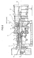
- Fig. 1 is a schematic of an upstream portion of a turbine in a gas turbine according to an embodiment of the present invention
- Fig. 2 is a front view of main parts of the turbine disk in the gas turbine according to the embodiment
- Fig. 3 is a cross-sectional view along a line III-III in Fig. 2
- Fig. 4 is a cross-sectional view along a line IV-IV in Fig. 2
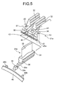
- Fig. 5 is an exploded perspective view of a rotor blade in the gas turbine according to the embodiment
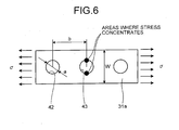
- Fig. 6 is an illustrative schematic representing a relationship between the diameter of a cooling hole, the interval therebetween, and a stress concentration factor;
- Fig. 1 is a schematic of an upstream portion of a turbine in a gas turbine according to an embodiment of the present invention
- Fig. 2 is a front view of main parts of the turbine disk in the gas turbine according to the embodiment
- Fig. 3 is a cross-sectional view along a line III-III in
- Fig. 7 is a graph indicating the stress concentration factor with respect to the diameter of the cooling holes and the interval therebetween;
- Fig. 8 is a schematic of a structure of the gas turbine according to the embodiment;
- Fig. 9 is a schematic representing a variation of the turbine disk in the gas turbine according to the embodiment.
- the gas turbine includes a compressor 11, a combustor 12, a turbine 13, and an exhaust chamber 14, and a generator not illustrated is connected to the turbine 13.
- the compressor 11 has an air inlet 15 that takes in air, and includes a plurality of compressor vanes 17 and rotor blades 18 arranged in an alternating manner within a compressor casing 16.
- An air bleeding manifold 19 is disposed outside thereof.
- the combustor 12 supplies fuel to compressed air that is compressed in the compressor 11, and burner ignition enables combustion.
- the turbine 13 includes a plurality of nozzles 21 and rotor blades 22 that are arranged in an alternating manner in a turbine casing 20.
- the exhaust chamber 14 includes an exhaust diffuser 23 continuing to the turbine 13.
- a rotor (turbine shaft) 24 is positioned penetrating through the centers of the compressor 11, the combustor 12, the turbine 13, and the exhaust chamber 14, and an end of the rotor 24 toward the compressor 11 is supported rotatably on a bearing 25, and the other end toward the exhaust chamber 14 is supported rotatably on a bearing 26.
- a plurality of disks are fixed to the rotor 24, and each of the rotor blades 18 and 22 are also fixed thereto, and a drive shaft of the generator, not illustrated, is connected to an end toward the exhaust chamber 14.
- Air collected via the air inlet 15 on the compressor 11 passes through the nozzles 21 and the rotor blades 22 and is compressed thereby to become compressed air having a high temperature and a high pressure.
- a predetermined fuel is injected to the compressed air for combustion in the combustor 12.
- Combustion gas that is a working fluid at a high temperature and a high pressure generated in the combustor 12 passes through the nozzles 21 and the rotor blades 22 included in the turbine 13 to drive the rotor 24 in rotation, further to drive the generator connected to the rotor 24.
- Exhaust gas is converted into static pressure in the exhaust diffuser 23 in the exhaust chamber 14, and then released into the air.
- the nozzles 21a, 21b, ... are arranged in a flowing direction of fuel gas (in the direction indicated by an arrow in Fig. 1 ) in the turbine casing 20.
- Each of the nozzles 21a, 21b, ... are laid equally spaced therebetween along the circumferential direction of the turbine casing 20.
- Turbine disks 31a, 31b, ... are connected to the rotor 24 (see Fig. 8 ) in an integrally rotatable manner along an axial direction.
- Each of the turbine disks 31a, 31b, ... has the rotor blades 22a, 22b, ... fixed to the outer circumference thereof.
- Each of the rotor blades 22a, 22b ... are arranged equally spaced therebetween along the circumferential direction on each of the turbine disks 31a, 31b, ....
- the turbine disk 31a has a disk-like shape, and a plurality of fitting grooves 32, each of which is laid in the axial direction, is formed equally spaced therebetween in the circumferential direction on the outer circumference of the turbine disk.
- an axial direction communicating groove 33 is formed integrally with the fitting groove 32.
- a rotor blade body 35 is arranged upright integrally on top of a platform 34.
- a blade root (fitting protrusion) 36 that can be fitted into the fitting groove 32 is formed integrally to the bottom of the platform 34.
- a protrusion 36a, protruding toward one side in the axial direction, is formed integrally to the bottom of the blade root 36.
- a ring-shaped circumferential flange 37 is formed on one side of the turbine disk 31a in the axial direction (on the front edge side). Cutouts 38 each of which positioned along the same line as each of the axial direction communicating grooves 33 are formed in the circumferential flange 37.
- the protrusion 36a on the blade root 36 can be fitted into the cutout 38 on the turbine disk 31a, and a seal piece 39 can be fitted thereto.
- the blade root 36 is slid and fitted into the fitting groove 32 to mount the rotor blades 22a to the turbine disk 31a.
- a space is formed between the bottom surface of the blade root 36 and the axial direction communicating groove 33, to form an axial direction communicating channel 40.
- a cooling passage 41 that is formed inside the rotor blade 22a is communicatively connected to the axial direction communicating channel 40.
- the protrusion 36a on the blade root 36 fits into the cutout 38 on the turbine disk 31a, and the seal piece 39 is fitted thereto from outside to seal a part of one side of the axial direction communicating channel 40.
- the seal piece 39 has a hook 39a bending from a horizontal direction toward an upright direction, and the hook 39a is locked into a cutout 36b on the blade root 36 with the blade root 36 fitted into the cutout 38, thus the seal piece 39 is prevented from falling off.
- the other side (rear edge side) of the axial direction communicating channel 40 is also sealed by a seal piece not illustrated fitted therein.
- first cooling holes 42 each of which penetrates the turbine disk from inside toward outside thereof and is communicatively connected to the cooling passage 41 in each of the rotor blade 22a is arranged in the circumferential direction.
- second cooling holes 43 each of which is located between the first cooling holes 42 and penetrates the turbine disk from the inside toward the outside thereof is arranged in the circumferential direction.
- the first cooling holes 42 are arranged correspondingly to the axial direction communicating channels 40; the base ends thereof open into the inside of the turbine casing 20; and the leading ends thereof are communicatively connected to the axial direction communicating channels 40.
- the base ends of the second cooling hole 43 open into the inside of the turbine casing 20, in the same manner as the first cooling hole 42.
- the leading ends of the second cooling holes 43 penetrate through the circumferential flange 37, and are sealed by a plug 44 that is attached thereto.
- a ring-shaped radial direction communicating groove 45 is formed on an outer circumferential plane of the turbine disk 31a.
- a seal ring 46 is fixed to and seals an opening end of the radial direction communicating groove 45 to form an annular radial direction communicating channel 47.
- the radial direction communicating groove 45 runs across and is communicatively connected to each of the first cooling holes 42 and the second cooling holes 43.
- a screw portion 46a that is screwed into a screw portion 45a on the radial direction communicating groove 45 is formed on the inner circumference of the seal ring 46.
- a plurality of aligning protrusions 46b that can be brought in contact with a bottom 45b of the radial direction communicating groove 45 is formed with a predetermined space therebetween in the circumferential direction.
- the seal ring 46 is aligned and fixed, to form the radial direction communicating channel 47.
- Each of the tip ends of the first cooling holes 42 and the second cooling holes 43 is communicatively connected by way of the radial direction communicating channel 47.
- the radial direction communicating channel 47 is communicatively connected to the axial direction communicating channels 40.
- a cavity 52 partitioned by the turbine disk 31a and a cover 51 is arranged inside the turbine casing 20. Cooling air that has been bled from the compressor 11 and cooled is supplied into the cavity 52. The compressed air compressed in the compressor 11 (see Fig. 8 ) is sent into a cooler (not illustrated), cooled therein to a predetermined temperature, and then sent into the cavity 52. The cooling air (cooling gas) sent to the cavity 52 is sucked into each of the cooling holes 42 and 43 through a restrictor 53.
- the cooling air is supplied into the axial direction communicating channels 40 through the first cooling holes 42, and from the radial direction communicating channel 47 into the axial direction communicating channels 40 through the second cooling holes 43.
- the cooling air being supplied from the axial direction communicating channels 40 to the cooling passages 41, the rotor blades 22a are cooled.
- the concentration of the stress can be reduced.
- the inner diameter of the cooling holes 42 and 43 is a; and the distance between the centers of the adjacent cooling holes 42 and 43 is b; and the stress concentration factor is [sigma].
- the greater a/b is, the smaller the stress concentration factor [sigma] becomes.
- the turbine disk 31a is firmly connected to the rotor 24; the rotor 24 is supported rotatably; a plurality of the rotor blades 22a is arranged along the outer circumference of the turbine disk 31a in the circumferential direction; the first cooling holes 42 each of which penetrates the turbine disk from inside toward outside thereof and is communicatively connected to the cooling passage 41 inside the rotor blades 22a are arranged in the circumferential direction in the turbine disk 31a; and the second cooling holes 43 are arranged between the respective first cooling holes 42 and penetrate the turbine disk from inside toward outside thereof.
- the first cooling holes 42 and the second cooling holes 43 are arranged in an alternating manner along the circumferential direction to reduce the distance between a plurality of cooling holes 42 and 43 in the circumferential direction. Therefore, the concentration of the stress applied to the area around each of the cooling holes 42 and 43 upon rotating the rotor can be alleviated. Furthermore, by adding the second cooling holes 43, the turbine disk 31a can be reduced in weight. As a result, durability of the turbine disk 31a can be improved.
- the first cooling holes 42 and the second cooling holes 43 allow the cooling gas to be supplied from the base ends thereof; the leading ends of the first cooling hole 42 and the second cooling holes 43 are communicatively connected via the radial direction communicating channel 47 that is laid along the circumferential direction.
- the cooling gas is supplied from the first cooling holes 42 and the second cooling holes 43 into the cooling passage 41 in the rotor blade 22a via the radial direction communicating channel 47.
- the area of the cooling gas passage can be increased, to reduce the pressure loss and to improve the efficiency of cooling the rotor blade 22a.
- the blade roots 36 of the rotor blades 22a are fitted into a large number of respective fitting grooves 32 arranged in the outer circumference of the turbine disk in the circumferential direction to form the axial direction communicating channels 40 in the space therebetween along the axial direction;
- the first cooling holes 42 are arranged correspondingly to the axial direction communicating channels 40 in the circumferential direction, and the leading ends thereof are communicatively connected to the radial direction communicating channel 47 and the axial direction communicating channels 40;
- the second cooling holes 43 are arranged between the first cooling holes 42 in the circumferential direction, and the leading ends thereof are sealed with the plug 44 and are communicatively connected to the radial direction communicating channel 47; and the first cooling holes 42 and the second cooling holes 43 are arranged at appropriate positions to supply the cooling gas to the cooling passage 41 in the rotor blade 22a effectively.
- the structure can thus be simplified.
- both ends of the axial direction communicating channel 40 are sealed with the seal pieces 39. Workability of the fitting groove 32 into which the blade root 36 of the rotor blade 22a is fitted can thus be improved.
- the seal piece 39 enables the axial direction communicating channel 40 with no leakage to be formed appropriately.
- the radial direction communicating channel 47 is provided in an annular shape by sealing the ring shaped radial direction communicating groove 45 with the seal ring 46.
- the gas turbine according to the embodiment includes the compressor 11, the combustor 12, and the turbine 13.
- the turbine 13 includes the turbine disks 31a, 31b, ... that are supported rotatably; and a plurality of the rotor blades 22a, 22b, ... that is arranged in the outer circumference of the turbine disks 31a, 31b, ... and has a cooling passage 41 formed therein.
- a plurality of the first cooling holes 42 each of which penetrates the turbine disk from the inside toward the outside thereof and is communicatively connected to the cooling passage 41 is arranged
- the second cooling holes 43 each of which is positioned between the first cooling holes 42 and that penetrates the turbine disk from the inside toward the outside thereof are arranged.
- the first cooling holes 42 and the second cooling holes 43 are arranged in an alternating manner in the circumferential direction, to reduce the distance between the cooling holes 42 and 43 in the circumferential direction; the concentration of the stress applied upon rotating the rotor to the area around each of the cooling holes 42 and 43 can be alleviated. Furthermore, by adding the second cooling holes 43, the turbine disk 31a can be reduced in weight to improve the durability. As a result, the output and the efficiency of the turbine can be improved.
- the first cooling holes 42 are arranged from the inside toward the outside of the turbine disk, and the second cooling holes 43 are arranged between the first cooling holes 42 from the inside toward the outside of the turbine disk; however, the structure is not limited thereto.
- a plurality of the second cooling holes may be arranged between the first cooling holes, or the inner diameter of the second cooling hole may be made smaller than that of the first cooling holes.
- the shape of the first cooling hole 42 and the second cooling holes 43 is not limited to a circle, but may also be another shape, such as an ellipse.
- first cooling holes 42 and the second cooling holes 43 arranged from the inside toward the outside of the turbine disk may also be arranged tilted in the axial direction with respect to the circumferential direction, as illustrated in Fig. 9 .
- concentration of the stress around the openings of the cooling holes can be alleviated.
- the second cooling holes according to the present invention are explained to be the second cooling holes 43 arranged between the first cooling holes 42 in the turbine disk 31a; however, the second cooling holes 43 may be second cooling holes with leading ends thereof sealed, without providing the radial direction communicating channel 47.
- Such a structure can also alleviate the concentration of the stress acting on the turbine disk, and can reduce the weight as well.
- the rotor with the turbine disk and the gas turbine according to the present invention improves the durability by alleviating the concentration of the stress acting on the turbine disk, and can be applied to any type of gas turbines.
Landscapes
- Engineering & Computer Science (AREA)
- Mechanical Engineering (AREA)
- General Engineering & Computer Science (AREA)
- Turbine Rotor Nozzle Sealing (AREA)
Claims (4)
- Ein Rotor (24), der drehbar gelagert werden soll, wobei der Rotor (24) eine Turbinenscheibe (31a, 31b) und eine Vielzahl von Rotorschaufeln (22a, 22b), die in einer jeweiligen Anzahl von Einsetznuten (32) an einem Umfang der Turbinenscheibe (31a, 31b) in einer Umfangsrichtung angeordnet sind, aufweist, wobei die Turbinenscheibe (31a, 31b) umfasst:eine Vielzahl von ersten Kühllöchern (42), die die Turbinenscheibe (31a, 31b) von einer Innenseite zu einer Außenseite derselben durchsetzen, die kommunizierend mit einem Kühldurchgang (41) verbunden sind, der im Inneren von jeder der Rotorschaufeln (22a, 22b) vorgesehen ist, und die in der Umfangsrichtung angeordnet sind, undzweite Kühllöcher (43), die zwischen jedem der ersten Kühllöcher (42) positioniert sind und die Turbinenscheibe (31a, 31b) von der Innenseite zu der Außenseite derselben durchsetzen,wobei Kühlgas von Basisenden der ersten Kühllöcher (42) und der zweiten Kühllöcher (43) zugeführt werden kann,dadurch gekennzeichnet, dassVorderenden der ersten Kühllöcher (42) und der zweiten Kühllöcher (43) kommunizierend mit einem Radialrichtungs-Verbindungskanal (47) verbunden sind, der in der Umfangsrichtung angeordnet ist, undIn die Einsetznuten (32), die an dem Außenumfang in der Umfangsrichtung angeordnet sind, jeweilige Einsetzvorsprünge (36) an den Rotorschaufeln (22a, 22b) eingesetzt sind, um Axialrichtungs-Verbindungskanäle (40) in Räumen zwischen den Einsetznuten (32) und den Rotorschaufeln (22a, 22b) entlang einer Axialrichtung zu bilden,wobei die ersten Kühllöcher (42) entsprechend den Axialrichtungs-Verbindungskanälen (40) in der Umfangsrichtung angeordnet sind, und die Vorderenden derselben kommunizierend mit dem Radialrichtungs-Verbindungskanal (47) und den Axialrichtungs-Verbindungskanälen (40) verbunden sind, undwobei die zweiten Kühllöcher (43) zwischen den ersten Kühllöchern (42) in der Umfangsrichtung angeordnet sind, und die Vorderenden verschlossen haben, und kommunizierend mit dem Radialrichtungs-Verbindungskanal (47) verbunden sind.
- Der Rotor (24) gemäß Anspruch 1, wobei beide Enden des Axialrichtungs-Verbindungskanals (40) mit Dichtungsstücken (39) verschlossen sind.
- Der Rotor (24) gemäß Anspruch 1 oder 2, wobei der Radialrichtungs-Verbindungskanal (47) in einer Ringform ausgebildet ist, indem eine ringförmige Verbindungsnut (45) mit einem Dichtungsring (46) verschlossen ist.
- Eine Gasturbine, bei der, im Betrieb, in einem Kompressor (11) komprimierte Luft durch Zuführen von Brennstoff zu dieser in einer Brennkammer (12) verbrannt wird, und ein somit erzeugtes Verbrennungsgas einer Turbine (13) zugeführt wird, um eine Drehantriebsenergie zu erhalten, wobei die Turbine (13) einen Rotor (24) gemäß einem der Ansprüche 1 bis 3, der drehbar gelagert ist, aufweist.
Applications Claiming Priority (2)
| Application Number | Priority Date | Filing Date | Title |
|---|---|---|---|
| JP2008046698A JP4939461B2 (ja) | 2008-02-27 | 2008-02-27 | タービンディスク及びガスタービン |
| PCT/JP2009/050551 WO2009107418A1 (ja) | 2008-02-27 | 2009-01-16 | タービンディスク及びガスタービン |
Publications (4)
| Publication Number | Publication Date |
|---|---|
| EP2246526A1 EP2246526A1 (de) | 2010-11-03 |
| EP2246526A4 EP2246526A4 (de) | 2014-03-05 |
| EP2246526B1 true EP2246526B1 (de) | 2015-03-18 |
| EP2246526B8 EP2246526B8 (de) | 2015-04-22 |
Family
ID=41015824
Family Applications (1)
| Application Number | Title | Priority Date | Filing Date |
|---|---|---|---|
| EP20090715480 Active EP2246526B8 (de) | 2008-02-27 | 2009-01-16 | Rotor, turbinenscheibe und gasturbine |
Country Status (6)
| Country | Link |
|---|---|
| US (1) | US8770919B2 (de) |
| EP (1) | EP2246526B8 (de) |
| JP (1) | JP4939461B2 (de) |
| KR (1) | KR101245094B1 (de) |
| CN (1) | CN101960092B (de) |
| WO (1) | WO2009107418A1 (de) |
Families Citing this family (14)
| Publication number | Priority date | Publication date | Assignee | Title |
|---|---|---|---|---|
| US20120183389A1 (en) * | 2011-01-13 | 2012-07-19 | Mhetras Shantanu P | Seal system for cooling fluid flow through a rotor assembly in a gas turbine engine |
| JP5791430B2 (ja) | 2011-08-29 | 2015-10-07 | 三菱日立パワーシステムズ株式会社 | ディスク吊り上げ用治具 |
| CN103233900B (zh) * | 2013-05-09 | 2018-02-06 | 林钧浩 | 管道轮增压通风压缩机 |
| CN104153882B (zh) * | 2013-05-15 | 2017-09-22 | 林钧浩 | 飞行器管道轮燃气发动机 |
| CN105275499B (zh) * | 2015-06-26 | 2016-11-30 | 中航空天发动机研究院有限公司 | 一种具有离心增压和封严效果的双辐板涡轮盘盘心进气结构 |
| US10018065B2 (en) * | 2015-09-04 | 2018-07-10 | Ansaldo Energia Ip Uk Limited | Flow control device for rotating flow supply system |
| KR101663306B1 (ko) * | 2015-10-02 | 2016-10-06 | 두산중공업 주식회사 | 가스터빈 디스크 |
| US10519857B2 (en) | 2016-10-24 | 2019-12-31 | Rolls-Royce Corporation | Disk with lattice features adapted for use in gas turbine engines |
| US11143041B2 (en) * | 2017-01-09 | 2021-10-12 | General Electric Company | Turbine have a first and second rotor disc and a first and second cooling fluid conduit wherein the second cooling fluid conduit is extended through an annular axially extended bore having a radially outer extent defined by a radially innermost surface of the rotor discs |
| JP7328794B2 (ja) | 2019-05-24 | 2023-08-17 | 三菱重工業株式会社 | ロータディスク、ロータ軸、タービンロータ、及びガスタービン |
| CN116201606B (zh) * | 2023-02-17 | 2025-09-23 | 清启动力(北京)科技有限公司 | 一种机械动叶片和轮盘的装配结构及燃气轮机 |
| CN116104586A (zh) * | 2023-04-11 | 2023-05-12 | 中国航发沈阳发动机研究所 | 一种涡轮转子叶片与涡轮盘的锁紧固定结构 |
| DE102023111513A1 (de) * | 2023-05-03 | 2024-11-07 | MTU Aero Engines AG | Rotorscheibe für einen Schaufelkranz |
| WO2025205631A1 (ja) * | 2024-03-27 | 2025-10-02 | 三菱パワー株式会社 | ロータディスク、ロータ軸、タービンロータ、及びガスタービン |
Family Cites Families (19)
| Publication number | Priority date | Publication date | Assignee | Title |
|---|---|---|---|---|
| GB617472A (en) * | 1946-10-02 | 1949-02-07 | Adrian Albert Lombard | Improvements in or relating to gas-turbine-engines |
| GB612097A (en) * | 1946-10-09 | 1948-11-08 | English Electric Co Ltd | Improvements in and relating to the cooling of gas turbine rotors |
| JPS62169201A (ja) * | 1986-01-22 | 1987-07-25 | Hitachi Ltd | 機器保護ユニツト |
| JPH0740642Y2 (ja) * | 1986-04-17 | 1995-09-20 | 三菱重工業株式会社 | ガスタービン動翼への冷却空気供給構造 |
| JPH0231355A (ja) * | 1988-07-20 | 1990-02-01 | Seiko Epson Corp | ヘッド構造 |
| JPH0231355U (de) * | 1988-08-19 | 1990-02-27 | ||
| JPH08218804A (ja) * | 1995-02-10 | 1996-08-27 | Mitsubishi Heavy Ind Ltd | タービンのシール装置 |
| DE19705442A1 (de) | 1997-02-13 | 1998-08-20 | Bmw Rolls Royce Gmbh | Turbinen-Laufradscheibe mit Kühlluftkanälen |
| JP3442959B2 (ja) * | 1997-02-21 | 2003-09-02 | 三菱重工業株式会社 | ガスタービン動翼の冷却媒体通路 |
| US5984636A (en) * | 1997-12-17 | 1999-11-16 | Pratt & Whitney Canada Inc. | Cooling arrangement for turbine rotor |
| EP0926311B1 (de) * | 1997-12-24 | 2003-07-09 | ALSTOM (Switzerland) Ltd | Rotor einer Strömungsmaschine |
| JPH11257019A (ja) * | 1998-03-12 | 1999-09-21 | Toshiba Corp | ガスタービン |
| JP2001012205A (ja) * | 1999-06-29 | 2001-01-16 | Mitsubishi Heavy Ind Ltd | ガスタービン動翼冷却流量調整構造 |
| JP3518447B2 (ja) * | 1999-11-05 | 2004-04-12 | 株式会社日立製作所 | ガスタービン,ガスタービン装置およびガスタービン動翼の冷媒回収方法 |
| JP3361501B2 (ja) * | 2000-03-02 | 2003-01-07 | 株式会社日立製作所 | 閉回路翼冷却タービン |
| GB0405679D0 (en) * | 2004-03-13 | 2004-04-21 | Rolls Royce Plc | A mounting arrangement for turbine blades |
| US6988367B2 (en) * | 2004-04-20 | 2006-01-24 | Williams International Co. L.L.C. | Gas turbine engine cooling system and method |
| EP1875058A4 (de) | 2005-04-25 | 2011-03-30 | Williams Int Co Llc | System und verfahren zum kühlen einer gasturbine |
| JP5129633B2 (ja) * | 2008-03-28 | 2013-01-30 | 三菱重工業株式会社 | 冷却通路用カバーおよび該カバーの製造方法ならびにガスタービン |
-
2008
- 2008-02-27 JP JP2008046698A patent/JP4939461B2/ja active Active
-
2009
- 2009-01-16 EP EP20090715480 patent/EP2246526B8/de active Active
- 2009-01-16 KR KR1020107018233A patent/KR101245094B1/ko active Active
- 2009-01-16 WO PCT/JP2009/050551 patent/WO2009107418A1/ja not_active Ceased
- 2009-01-16 US US12/864,006 patent/US8770919B2/en active Active
- 2009-01-16 CN CN2009801064385A patent/CN101960092B/zh active Active
Also Published As
| Publication number | Publication date |
|---|---|
| US20100290922A1 (en) | 2010-11-18 |
| JP4939461B2 (ja) | 2012-05-23 |
| KR101245094B1 (ko) | 2013-03-18 |
| EP2246526A1 (de) | 2010-11-03 |
| CN101960092A (zh) | 2011-01-26 |
| KR20100116619A (ko) | 2010-11-01 |
| WO2009107418A1 (ja) | 2009-09-03 |
| US8770919B2 (en) | 2014-07-08 |
| CN101960092B (zh) | 2013-09-11 |
| JP2009203870A (ja) | 2009-09-10 |
| EP2246526B8 (de) | 2015-04-22 |
| EP2246526A4 (de) | 2014-03-05 |
Similar Documents
| Publication | Publication Date | Title |
|---|---|---|
| EP2246526B1 (de) | Rotor, turbinenscheibe und gasturbine | |
| EP2216505B1 (de) | Abdeckplatte für Gasturbine | |
| EP2126285B1 (de) | Sperrsystem für eine turbinenverschlussplatte | |
| US8277177B2 (en) | Fluidic rim seal system for turbine engines | |
| EP3002410B1 (de) | Beschaufelte rotoranordnung mit sicherungsplatten und dichtplatten | |
| EP2206902A2 (de) | Turbinenkühlluft von einem Kreiselverdichter | |
| US20100275612A1 (en) | Direct transfer axial tangential onboard injector system (tobi) with self-supporting seal plate | |
| JP5108152B2 (ja) | タービンディスク上にシールプレートを備えたガスタービン | |
| JP2007120501A (ja) | 段間シール、タービンブレード、およびガスタービンエンジンの冷却されるロータとステータとの間におけるインタフェースシール | |
| CN102216567A (zh) | 叶片根部与叶轮盘之间具有安全板的燃气涡轮机 | |
| KR102055117B1 (ko) | 가스 터빈 로터, 가스 터빈 및 가스 터빈 설비 | |
| JP2006342797A (ja) | ガスタービンエンジンのシールアッセンブリ、ロータアッセンブリ、ロータアッセンブリ用ブレードおよび段間キャビティシール | |
| CN110431286B (zh) | 用于涡轮机的尖端平衡狭缝 | |
| EP2568202B1 (de) | Diskontinuierliche Ringdichtung | |
| US6554570B2 (en) | Turbine blade support assembly and a turbine assembly | |
| KR102028591B1 (ko) | 터빈 베인 조립체 및 이를 포함하는 가스터빈 | |
| CN108884714B (zh) | 包括通风间隔件的涡轮转子 | |
| JP2006342796A (ja) | ガスタービンエンジンのシールアッセンブリ、ロータアッセンブリおよびロータアッセンブリ用ブレード | |
| US11111803B2 (en) | Sealing structure between turbine rotor disk and interstage disk | |
| US11598265B2 (en) | Tangential on-board injector | |
| KR102031935B1 (ko) | 씰플레이트, 이를 포함하는 터빈 및 가스터빈 | |
| KR102887774B1 (ko) | 터빈 블레이드의 씰 조립구조와 이를 포함하는 가스 터빈 |
Legal Events
| Date | Code | Title | Description |
|---|---|---|---|
| PUAI | Public reference made under article 153(3) epc to a published international application that has entered the european phase |
Free format text: ORIGINAL CODE: 0009012 |
|
| 17P | Request for examination filed |
Effective date: 20100716 |
|
| AK | Designated contracting states |
Kind code of ref document: A1 Designated state(s): AT BE BG CH CY CZ DE DK EE ES FI FR GB GR HR HU IE IS IT LI LT LU LV MC MK MT NL NO PL PT RO SE SI SK TR |
|
| AX | Request for extension of the european patent |
Extension state: AL BA RS |
|
| DAX | Request for extension of the european patent (deleted) | ||
| A4 | Supplementary search report drawn up and despatched |
Effective date: 20140205 |
|
| RIC1 | Information provided on ipc code assigned before grant |
Ipc: F01D 5/00 20060101ALI20140130BHEP Ipc: F01D 5/02 20060101ALI20140130BHEP Ipc: F02C 7/18 20060101ALI20140130BHEP Ipc: F01D 5/08 20060101AFI20140130BHEP |
|
| REG | Reference to a national code |
Ref country code: DE Ref legal event code: R079 Ref document number: 602009030033 Country of ref document: DE Free format text: PREVIOUS MAIN CLASS: F01D0005080000 Ipc: F01D0005320000 |
|
| RIC1 | Information provided on ipc code assigned before grant |
Ipc: F01D 5/08 20060101ALI20140929BHEP Ipc: F01D 5/32 20060101AFI20140929BHEP Ipc: F01D 5/02 20060101ALI20140929BHEP Ipc: F01D 5/00 20060101ALI20140929BHEP Ipc: F02C 7/18 20060101ALI20140929BHEP |
|
| GRAP | Despatch of communication of intention to grant a patent |
Free format text: ORIGINAL CODE: EPIDOSNIGR1 |
|
| INTG | Intention to grant announced |
Effective date: 20141113 |
|
| GRAS | Grant fee paid |
Free format text: ORIGINAL CODE: EPIDOSNIGR3 |
|
| GRAA | (expected) grant |
Free format text: ORIGINAL CODE: 0009210 |
|
| AK | Designated contracting states |
Kind code of ref document: B1 Designated state(s): AT BE BG CH CY CZ DE DK EE ES FI FR GB GR HR HU IE IS IT LI LT LU LV MC MK MT NL NO PL PT RO SE SI SK TR |
|
| REG | Reference to a national code |
Ref country code: GB Ref legal event code: FG4D |
|
| RIN1 | Information on inventor provided before grant (corrected) |
Inventor name: HASHIMOTO, SHINYA Inventor name: ARASE, KENICHI |
|
| RAP2 | Party data changed (patent owner data changed or rights of a patent transferred) |
Owner name: MITSUBISHI HITACHI POWER SYSTEMS, LTD. |
|
| REG | Reference to a national code |
Ref country code: CH Ref legal event code: EP |
|
| REG | Reference to a national code |
Ref country code: IE Ref legal event code: FG4D |
|
| REG | Reference to a national code |
Ref country code: DE Ref legal event code: R082 Ref document number: 602009030033 Country of ref document: DE Representative=s name: PATENTANWAELTE HENKEL, BREUER & PARTNER, DE Ref country code: DE Ref legal event code: R082 Ref document number: 602009030033 Country of ref document: DE Representative=s name: PATENTANWAELTE HENKEL, BREUER & PARTNER MBB, DE |
|
| RAP2 | Party data changed (patent owner data changed or rights of a patent transferred) |
Owner name: MITSUBISHI HITACHI POWER SYSTEMS, LTD. |
|
| REG | Reference to a national code |
Ref country code: AT Ref legal event code: REF Ref document number: 716718 Country of ref document: AT Kind code of ref document: T Effective date: 20150415 |
|
| REG | Reference to a national code |
Ref country code: DE Ref legal event code: R096 Ref document number: 602009030033 Country of ref document: DE Effective date: 20150430 |
|
| REG | Reference to a national code |
Ref country code: NL Ref legal event code: VDEP Effective date: 20150318 |
|
| REG | Reference to a national code |
Ref country code: NL Ref legal event code: VDEP Effective date: 20150318 |
|
| PG25 | Lapsed in a contracting state [announced via postgrant information from national office to epo] |
Ref country code: SE Free format text: LAPSE BECAUSE OF FAILURE TO SUBMIT A TRANSLATION OF THE DESCRIPTION OR TO PAY THE FEE WITHIN THE PRESCRIBED TIME-LIMIT Effective date: 20150318 Ref country code: HR Free format text: LAPSE BECAUSE OF FAILURE TO SUBMIT A TRANSLATION OF THE DESCRIPTION OR TO PAY THE FEE WITHIN THE PRESCRIBED TIME-LIMIT Effective date: 20150318 Ref country code: NO Free format text: LAPSE BECAUSE OF FAILURE TO SUBMIT A TRANSLATION OF THE DESCRIPTION OR TO PAY THE FEE WITHIN THE PRESCRIBED TIME-LIMIT Effective date: 20150618 Ref country code: LT Free format text: LAPSE BECAUSE OF FAILURE TO SUBMIT A TRANSLATION OF THE DESCRIPTION OR TO PAY THE FEE WITHIN THE PRESCRIBED TIME-LIMIT Effective date: 20150318 Ref country code: FI Free format text: LAPSE BECAUSE OF FAILURE TO SUBMIT A TRANSLATION OF THE DESCRIPTION OR TO PAY THE FEE WITHIN THE PRESCRIBED TIME-LIMIT Effective date: 20150318 |
|
| REG | Reference to a national code |
Ref country code: AT Ref legal event code: MK05 Ref document number: 716718 Country of ref document: AT Kind code of ref document: T Effective date: 20150318 |
|
| REG | Reference to a national code |
Ref country code: LT Ref legal event code: MG4D |
|
| PG25 | Lapsed in a contracting state [announced via postgrant information from national office to epo] |
Ref country code: LV Free format text: LAPSE BECAUSE OF FAILURE TO SUBMIT A TRANSLATION OF THE DESCRIPTION OR TO PAY THE FEE WITHIN THE PRESCRIBED TIME-LIMIT Effective date: 20150318 Ref country code: GR Free format text: LAPSE BECAUSE OF FAILURE TO SUBMIT A TRANSLATION OF THE DESCRIPTION OR TO PAY THE FEE WITHIN THE PRESCRIBED TIME-LIMIT Effective date: 20150619 |
|
| PG25 | Lapsed in a contracting state [announced via postgrant information from national office to epo] |
Ref country code: NL Free format text: LAPSE BECAUSE OF FAILURE TO SUBMIT A TRANSLATION OF THE DESCRIPTION OR TO PAY THE FEE WITHIN THE PRESCRIBED TIME-LIMIT Effective date: 20150318 |
|
| PG25 | Lapsed in a contracting state [announced via postgrant information from national office to epo] |
Ref country code: PT Free format text: LAPSE BECAUSE OF FAILURE TO SUBMIT A TRANSLATION OF THE DESCRIPTION OR TO PAY THE FEE WITHIN THE PRESCRIBED TIME-LIMIT Effective date: 20150720 Ref country code: RO Free format text: LAPSE BECAUSE OF FAILURE TO SUBMIT A TRANSLATION OF THE DESCRIPTION OR TO PAY THE FEE WITHIN THE PRESCRIBED TIME-LIMIT Effective date: 20150318 Ref country code: CZ Free format text: LAPSE BECAUSE OF FAILURE TO SUBMIT A TRANSLATION OF THE DESCRIPTION OR TO PAY THE FEE WITHIN THE PRESCRIBED TIME-LIMIT Effective date: 20150318 Ref country code: EE Free format text: LAPSE BECAUSE OF FAILURE TO SUBMIT A TRANSLATION OF THE DESCRIPTION OR TO PAY THE FEE WITHIN THE PRESCRIBED TIME-LIMIT Effective date: 20150318 Ref country code: SK Free format text: LAPSE BECAUSE OF FAILURE TO SUBMIT A TRANSLATION OF THE DESCRIPTION OR TO PAY THE FEE WITHIN THE PRESCRIBED TIME-LIMIT Effective date: 20150318 Ref country code: ES Free format text: LAPSE BECAUSE OF FAILURE TO SUBMIT A TRANSLATION OF THE DESCRIPTION OR TO PAY THE FEE WITHIN THE PRESCRIBED TIME-LIMIT Effective date: 20150318 |
|
| PG25 | Lapsed in a contracting state [announced via postgrant information from national office to epo] |
Ref country code: IS Free format text: LAPSE BECAUSE OF FAILURE TO SUBMIT A TRANSLATION OF THE DESCRIPTION OR TO PAY THE FEE WITHIN THE PRESCRIBED TIME-LIMIT Effective date: 20150718 Ref country code: PL Free format text: LAPSE BECAUSE OF FAILURE TO SUBMIT A TRANSLATION OF THE DESCRIPTION OR TO PAY THE FEE WITHIN THE PRESCRIBED TIME-LIMIT Effective date: 20150318 Ref country code: AT Free format text: LAPSE BECAUSE OF FAILURE TO SUBMIT A TRANSLATION OF THE DESCRIPTION OR TO PAY THE FEE WITHIN THE PRESCRIBED TIME-LIMIT Effective date: 20150318 |
|
| REG | Reference to a national code |
Ref country code: DE Ref legal event code: R097 Ref document number: 602009030033 Country of ref document: DE |
|
| PG25 | Lapsed in a contracting state [announced via postgrant information from national office to epo] |
Ref country code: IT Free format text: LAPSE BECAUSE OF FAILURE TO SUBMIT A TRANSLATION OF THE DESCRIPTION OR TO PAY THE FEE WITHIN THE PRESCRIBED TIME-LIMIT Effective date: 20150318 |
|
| PLBE | No opposition filed within time limit |
Free format text: ORIGINAL CODE: 0009261 |
|
| STAA | Information on the status of an ep patent application or granted ep patent |
Free format text: STATUS: NO OPPOSITION FILED WITHIN TIME LIMIT |
|
| PG25 | Lapsed in a contracting state [announced via postgrant information from national office to epo] |
Ref country code: DK Free format text: LAPSE BECAUSE OF FAILURE TO SUBMIT A TRANSLATION OF THE DESCRIPTION OR TO PAY THE FEE WITHIN THE PRESCRIBED TIME-LIMIT Effective date: 20150318 |
|
| 26N | No opposition filed |
Effective date: 20151221 |
|
| PG25 | Lapsed in a contracting state [announced via postgrant information from national office to epo] |
Ref country code: SI Free format text: LAPSE BECAUSE OF FAILURE TO SUBMIT A TRANSLATION OF THE DESCRIPTION OR TO PAY THE FEE WITHIN THE PRESCRIBED TIME-LIMIT Effective date: 20150318 |
|
| PG25 | Lapsed in a contracting state [announced via postgrant information from national office to epo] |
Ref country code: BE Free format text: LAPSE BECAUSE OF NON-PAYMENT OF DUE FEES Effective date: 20160131 |
|
| PG25 | Lapsed in a contracting state [announced via postgrant information from national office to epo] |
Ref country code: BE Free format text: LAPSE BECAUSE OF FAILURE TO SUBMIT A TRANSLATION OF THE DESCRIPTION OR TO PAY THE FEE WITHIN THE PRESCRIBED TIME-LIMIT Effective date: 20150318 Ref country code: LU Free format text: LAPSE BECAUSE OF FAILURE TO SUBMIT A TRANSLATION OF THE DESCRIPTION OR TO PAY THE FEE WITHIN THE PRESCRIBED TIME-LIMIT Effective date: 20160116 |
|
| REG | Reference to a national code |
Ref country code: CH Ref legal event code: PL |
|
| GBPC | Gb: european patent ceased through non-payment of renewal fee |
Effective date: 20160116 |
|
| PG25 | Lapsed in a contracting state [announced via postgrant information from national office to epo] |
Ref country code: MC Free format text: LAPSE BECAUSE OF FAILURE TO SUBMIT A TRANSLATION OF THE DESCRIPTION OR TO PAY THE FEE WITHIN THE PRESCRIBED TIME-LIMIT Effective date: 20150318 |
|
| REG | Reference to a national code |
Ref country code: FR Ref legal event code: ST Effective date: 20160930 |
|
| PG25 | Lapsed in a contracting state [announced via postgrant information from national office to epo] |
Ref country code: GB Free format text: LAPSE BECAUSE OF NON-PAYMENT OF DUE FEES Effective date: 20160116 Ref country code: LI Free format text: LAPSE BECAUSE OF NON-PAYMENT OF DUE FEES Effective date: 20160131 Ref country code: CH Free format text: LAPSE BECAUSE OF NON-PAYMENT OF DUE FEES Effective date: 20160131 |
|
| REG | Reference to a national code |
Ref country code: IE Ref legal event code: MM4A |
|
| PG25 | Lapsed in a contracting state [announced via postgrant information from national office to epo] |
Ref country code: FR Free format text: LAPSE BECAUSE OF NON-PAYMENT OF DUE FEES Effective date: 20160201 |
|
| PG25 | Lapsed in a contracting state [announced via postgrant information from national office to epo] |
Ref country code: IE Free format text: LAPSE BECAUSE OF NON-PAYMENT OF DUE FEES Effective date: 20160116 |
|
| PG25 | Lapsed in a contracting state [announced via postgrant information from national office to epo] |
Ref country code: MT Free format text: LAPSE BECAUSE OF FAILURE TO SUBMIT A TRANSLATION OF THE DESCRIPTION OR TO PAY THE FEE WITHIN THE PRESCRIBED TIME-LIMIT Effective date: 20150318 |
|
| PG25 | Lapsed in a contracting state [announced via postgrant information from national office to epo] |
Ref country code: HU Free format text: LAPSE BECAUSE OF FAILURE TO SUBMIT A TRANSLATION OF THE DESCRIPTION OR TO PAY THE FEE WITHIN THE PRESCRIBED TIME-LIMIT; INVALID AB INITIO Effective date: 20090116 Ref country code: CY Free format text: LAPSE BECAUSE OF FAILURE TO SUBMIT A TRANSLATION OF THE DESCRIPTION OR TO PAY THE FEE WITHIN THE PRESCRIBED TIME-LIMIT Effective date: 20150318 |
|
| PG25 | Lapsed in a contracting state [announced via postgrant information from national office to epo] |
Ref country code: MT Free format text: LAPSE BECAUSE OF FAILURE TO SUBMIT A TRANSLATION OF THE DESCRIPTION OR TO PAY THE FEE WITHIN THE PRESCRIBED TIME-LIMIT Effective date: 20160131 Ref country code: MK Free format text: LAPSE BECAUSE OF FAILURE TO SUBMIT A TRANSLATION OF THE DESCRIPTION OR TO PAY THE FEE WITHIN THE PRESCRIBED TIME-LIMIT Effective date: 20150318 Ref country code: TR Free format text: LAPSE BECAUSE OF FAILURE TO SUBMIT A TRANSLATION OF THE DESCRIPTION OR TO PAY THE FEE WITHIN THE PRESCRIBED TIME-LIMIT Effective date: 20150318 |
|
| PG25 | Lapsed in a contracting state [announced via postgrant information from national office to epo] |
Ref country code: BG Free format text: LAPSE BECAUSE OF FAILURE TO SUBMIT A TRANSLATION OF THE DESCRIPTION OR TO PAY THE FEE WITHIN THE PRESCRIBED TIME-LIMIT Effective date: 20150318 |
|
| REG | Reference to a national code |
Ref country code: DE Ref legal event code: R082 Ref document number: 602009030033 Country of ref document: DE Representative=s name: HENKEL & PARTNER MBB PATENTANWALTSKANZLEI, REC, DE Ref country code: DE Ref legal event code: R081 Ref document number: 602009030033 Country of ref document: DE Owner name: MITSUBISHI POWER, LTD., JP Free format text: FORMER OWNER: MITSUBISHI HITACHI POWER SYSTEMS, LTD., YOKOHAMA, KANAGAWA, JP |
|
| PGFP | Annual fee paid to national office [announced via postgrant information from national office to epo] |
Ref country code: DE Payment date: 20241203 Year of fee payment: 17 |