EP2246505A1 - Serrure a pêne coulant verrouillable par genouillère - Google Patents
Serrure a pêne coulant verrouillable par genouillère Download PDFInfo
- Publication number
- EP2246505A1 EP2246505A1 EP10160509A EP10160509A EP2246505A1 EP 2246505 A1 EP2246505 A1 EP 2246505A1 EP 10160509 A EP10160509 A EP 10160509A EP 10160509 A EP10160509 A EP 10160509A EP 2246505 A1 EP2246505 A1 EP 2246505A1
- Authority
- EP
- European Patent Office
- Prior art keywords
- bolt
- sliding
- toggle
- lock
- core
- Prior art date
- Legal status (The legal status is an assumption and is not a legal conclusion. Google has not performed a legal analysis and makes no representation as to the accuracy of the status listed.)
- Withdrawn
Links
Images


Classifications
-
- E—FIXED CONSTRUCTIONS
- E05—LOCKS; KEYS; WINDOW OR DOOR FITTINGS; SAFES
- E05B—LOCKS; ACCESSORIES THEREFOR; HANDCUFFS
- E05B47/00—Operating or controlling locks or other fastening devices by electric or magnetic means
- E05B47/02—Movement of the bolt by electromagnetic means; Adaptation of locks, latches, or parts thereof, for movement of the bolt by electromagnetic means
- E05B47/026—Movement of the bolt by electromagnetic means; Adaptation of locks, latches, or parts thereof, for movement of the bolt by electromagnetic means the bolt moving rectilinearly
-
- E—FIXED CONSTRUCTIONS
- E05—LOCKS; KEYS; WINDOW OR DOOR FITTINGS; SAFES
- E05B—LOCKS; ACCESSORIES THEREFOR; HANDCUFFS
- E05B47/00—Operating or controlling locks or other fastening devices by electric or magnetic means
- E05B47/0001—Operating or controlling locks or other fastening devices by electric or magnetic means with electric actuators; Constructional features thereof
- E05B47/0002—Operating or controlling locks or other fastening devices by electric or magnetic means with electric actuators; Constructional features thereof with electromagnets
Definitions
- the present invention relates to an electrically operated lock that can be used, for example, for closing doors or, more generally, a flap hinged at an edge of an opening in a wall to be movable between a position for disengaging the opening and a door shutter position of the aperture.
- a lock which comprises a plate or headrest on one side of which are mounted a bolt for sliding between an active position projecting from an opposite face of the headrest and an inactive retracted position, and a device for controlling the bolt between these two positions .
- the control device comprises a slider which is associated with an electric motor to be driven in translation perpendicular to the sliding direction of the bolt between a locking position and an unlocking position.
- the slide is connected to the bolt by a mechanism for converting the translation of the slide between its locking position and its unlocking position in a sliding of the bolt between its active position and its inactive position respectively.
- Such a lock is more particularly intended to be embedded in a housing made in the thickness of the frame of the door so that the headboard is flush with one side thereof.
- the perpendicular arrangement of the slide and the bolt allows the realization of small locks.
- the motor drives in rotation, about an axis parallel to the translation direction of the slide, a cylinder provided externally with a helical thread and a flat which extends over the entire length of the cylinder and is devoid of helical thread.
- An operating knob is integral with the slide and is arranged to cooperate with the helical thread of the cylinder. So, the engine is capable, by turning, to move the slide between its locking position and its unlocking position by the cooperation of the helical thread and the operating knob. At each of these positions, the flat is in front of the slide and the operating knob is disengaged from the helical thread. The slider can then be maneuvered between its two positions by means of an additional control device such as the bit of a cylinder actuated by means of a key.
- Means have been proposed to simplify the structure of the transmission chain of the movement generated by the electric motor to the slider.
- An object of the invention is to remedy at least in part the aforementioned drawbacks.
- a lock comprising a headrest on which are mounted a bolt sliding between a locked position projecting from the headrest and a position released back from the locked position, and locking means of the bolt in the locked position, the lock also comprising a strike intended to be mounted facing the bolt to receive it when the bolt is in the vicinity of the locked position.
- the locking means comprise a toggle joint which connects the bolt to the headrest and has a state of bracing in which the toggle joint holds the bolt in the locked position and a release state in which the toggle allows a movement of the bolt between its position unobstructed and an intermediate position between the disengaged position and the locked position.
- the locking means comprise at least one actuating member of the toggle joint between its two states and the keeper and the bolt are shaped so that the bolt is flowing between the intermediate position and the released position, an elastic return device reminding the bolt to its intermediate position.
- the toggle When the toggle is in its unlocked state, the door to which the lock is associated can be closed and open without having to manipulate the bolt which is brought from its intermediate position to its disengaged position cooperating with the striker.
- the toggle in its blocking state opposes any movement of the bolt out of its locked position.
- the displacement of the hinge of the toggle necessary for its passage from one state to another is relatively low and only the brace of the toggle bracket maintains the bolt without any effort being exerted by the locking means. This allows the use of locking means having a relatively compact structure.
- the toggle allows relative latitude in positioning the locking means relative to the bolt.
- the actuating member comprises a linear electromagnet having a sliding core extending in a direction substantially perpendicular to the sliding direction of the bolt and, preferably, the electromagnet is a single acting electromagnet arranged to maintain the knee lever in its blocking state when it is supplied with electrical energy.
- the lock of the invention is in this embodiment an electric lock with rupture or positive security in which a power failure of the lock causes the release of the bolt.
- the structure of the invention allows to use a linear electromagnet whose short stroke does not allow it to be usually used in electric locks.
- the actuating member comprises two coaxial electromagnets which are mounted in opposition and have respectively a first sliding core and a second sliding core extending in a direction substantially perpendicular to the sliding direction of the bolt, the first sliding core directly actuating the toggle joint and the second sliding core actuating the first sliding core, the electromagnets being mounted to actuate the toggle respectively to its blocking state and to its unlocking state, the elastic return device acts on at least the first sliding core to recall it in positions respectively corresponding to the locking state of the toggle and a folded state of the toggle in which the toggle keeps the bolt in the released position.
- the lock of the invention is in this embodiment an electric transmission lock in which the bolt remains in its position in case of failure of the power supply of the lock.
- the actuating member comprises a device for elastically holding the cores in their position corresponding to the intermediate position of the bolt.
- the return device thus has a simple and compact structure.
- the striker comprises at least one cam surface to cooperate with the bolt and bring it from its intermediate position to its unlocked position during a displacement of the bolt in a direction substantially perpendicular to its direction of sliding, the surface of cam being integral with a slide mounted in the striker for sliding parallel to the sliding direction being elastically biased towards an entrance opening of the bolt in the striker.
- the stroke of the slider makes it possible to catch up with the assembly games of the headrest and the striker.
- the lock described herein is intended to equip a fixed frame set in an opening of a wall and on which is hinged a panel forming a leaf, for example a door.
- the lock is in this case arranged to form a lock type built in which is arranged in a recess formed in a side of the frame opposite the articulation of the panel.
- the lock can also be mounted in a housing formed on a panel edge.
- the lock according to the first embodiment of the invention comprises a headrest 1 elongated on a face 2 of which are mounted a bolt 3 for sliding perpendicularly to the headrest 1 between a locked position (shown in FIG. figure 1 ) projecting from an opposite face 4 of the headrest and an unobstructed position (shown in FIG. figure 3 ) retracted into the headrest 1, and a device, generally designated 5, blocking the bolt 3 in the locked position.
- the headboard 1 here comprises a plate having opposite faces forming the faces 2 and 4 and ravens projecting from the face 2 to support the various elements of the lock: the headrest is here made in one piece by molding.
- a housing 6 is fixed on the face 2 of the headrest 1 to cover the bolt 3 and the locking device 5.
- the locking device 5 comprises a toggle joint 7, comprising two links articulated to each other, which is mounted behind the bolt 3 and connects the bolt 3 to the headrest 1.
- the toggle lever 7 has a blocking state in which the knee brace 7 is braced and holds the bolt 3 in the locked position and a folded state in which the toggle 7 is bent and the bolt 3 is in its disengaged position.
- the rods In the blocking state, the rods extend substantially along the direction of sliding, the point of articulation of the links between them bearing against a stop 8 located on one side of an alignment axis 9 rods opposite the pivot point of the toggle 9 when the latter is in its folded state.
- the abutment 8 is here formed by a stud of a screw engaged in the headrest 1 so as to allow by screwing or unscrewing an adjustment of the position of the abutment 8 relative to the alignment axis 9 of the rods.
- the point of articulation of the toggle joint 7 to the bolt 3 and the articulation point of the toggle joint 7 to the headrest 1 are aligned on the sliding axis 9.
- the locking device comprises an actuating member of the toggle joint 7 between its blocking state and an unlocking state in which the folding of the toggle joint 9 has been initiated by detaching the point of articulation of the links from the abutment 8 and bringing the point of articulation of the links on the side of the axis 9 to the unlocking state allows the bolt 3 to move between its disengaged position and a waiting position (shown in FIG. figure 2 ) intermediate between the disengaged position and the locked position.
- the actuating member comprises a linear electromagnet 10 which is mounted on the headrest 1 and has a sliding core 11 extending in a direction substantially perpendicular to the sliding axis 9 of the bolt 3.
- the electromagnet 10 is an electromagnet a simple effect which is arranged to bring the toggle 7 in its blocking state when it is supplied with electrical energy and whose core 11 has a useful stroke of about 5 mm (the core 11 can however be moved beyond its course useful when the electromagnet 10 is not powered).
- the sliding core 11 has its lower end which is secured to a yoke 16 which comprises an outer cylindrical surface slidably received in a housing of the headrest 1 and which is articulated at one end 19.1 of a slider 19 having, on the opposite side, an end 19.2 connected to the point of articulation of the links of the toggle joint 7.
- the actuating device also comprises an elastic return device recalling the bolt 3 to its intermediate position from its unobstructed position.
- the return device here comprises a spring 12 mounted around the sliding core 11 of the electromagnet 10 to bear, on the one hand, on the headrest 1 and, on the other hand, on a washer 17 intended to cooperate with a shoulder formed on the yoke 16 secured to the sliding core 11.
- the lock further comprises an additional actuating member comprising a cylinder 13 (shown in double dotted line) integral with the face 2 of the headrest 1 and equipped with a movable bit 14 for cooperate with a latch 15 arranged in a latch guide 20 having an end slidably received in a housing of the headrest 1 and an opposite end connected to the yoke.
- a cylinder 13 shown in double dotted line
- the cylinder 13 is designed to cooperate in a conventional manner with a key arranged to enable the mobile blade 14 to be operated.
- the slider 19 has a slightly curved shape to prevent the cylinder hinders the movement of the slider.
- the actuating device finally comprises a spring 24 mounted around the latch guide 20 between the headrest 1 and the yoke 16 to resiliently bias the bolt 3 in its intermediate position from its locked position.
- the lock also comprises a striker 21 intended to be mounted on the leaf next to the bolt 3 to receive it when the leaf is closed and the bolt 3 is in the vicinity of the locked position.
- the striker 21 and the bolt 3 are shaped so that the bolt 3 is flowing between the intermediate position and the released position.
- the striker 21 comprises for this purpose a slider 23 having a receiving recess of a free end 18 of the bolt 3.
- the receiving recess comprises surfaces 22 arranged in V at 90 ° with respect to each other.
- the free end 18 of the bolt 3 is tapered and also has two faces at 90 ° to each other.
- the surfaces 22 are arranged to cooperate with the free end 18 of the bolt 3 and bring it in the manner of a cam from its intermediate position to its unlocked position during a displacement of the bolt 3 in a direction substantially perpendicular to its direction of sliding in one direction of opening of the door.
- the slider 23 is mounted in the striker 21 to slide parallel to the sliding direction being resiliently biased towards an inlet opening of the free end 18 of the bolt 3 in the striker 21.
- the slider 23 is here in one piece of polyethylene terephthalate incorporating a solid lubricant.
- the bolt 3 When the door is closed and the electromagnet 10 is energized, the bolt 3 is held in the locked position by the toggle joint 7 maintained in its blocking state by the electromagnet 10 (FIG. figure 1 ). The free end 18 of the bolt 3 is received in the receiving recess formed in the slider 23.
- the door can be opened by pressing a control button, or a code keyboard, which temporarily cuts off the supply of the electromagnet 10 which brings the toggle joint 7 into its unlocking state and thus the bolt 3 in its intermediate position. waiting ( figure 2 ).
- a force of displacement of the flap from its closed position to its open position exerted by the user then causes a lateral displacement of the free end 18 of the bolt 3 with respect to one of the surfaces 22 which will move the bolt 3 of its intermediate position. waiting towards its open position allowing the opening of the wing ( figure 3 ).
- This sliding of the bolt 3 causes the folding of the toggle 7 causing a vertical sliding of the slide 19, the yoke 16, and the core 11. During this sliding the yoke 16 moves the washer 17 to the electromagnet 10 causing compression of the spring 12.
- the spring 12 brings the bolt 3 back to its intermediate waiting position as soon as its free end 18 leaves the support of the striker 21.
- the arrival in the intermediate position of the bolt 3 corresponds to the arrival of the washer 17 bearing against the headrest 1.
- the electromagnet 10 again moves the bolt 3 in its locked position under the effect of a door closing detector or a timer restoring the power supply of the electromagnet 10.
- the displacement of the bolt is obtained by a displacement of the core driving the yoke 16 and slide 11 to lock the toggle 7 in its blocking state by compressing the spring 24.
- the door can be opened also by actuating the moving bit 14 by means of a key engaged in the cylinder 13.
- the rotation of the bit also controls the breaking of the supply of the electromagnet 10.
- the bolt 3 In case of accidental interruption of the supply of the electromagnet 10, the bolt 3 is in the intermediate position allowing the opening and closing of the door but not its locking. This lock is said to break.
- the actuating member comprises, as previously, an electromagnet 10 with a core 11, a washer 17, a spring 12, a yoke 16, and a slider 19 mounted as in the first embodiment on the headrest 1 to act on a knee pad 7.
- the actuating member has no spring resiliently biasing the slide 19 in a corresponding position. at the intermediate position of the bolt 3.
- This spring is replaced in the second embodiment by an electromagnetic actuator 30 coaxial with the electromagnetic actuator 10 and mounted in opposition thereto.
- the electromagnetic actuator 30 is a linear electromagnet comprising a core 31 extending in the extension of the core 11 and connected to the core 11 by a connecting rod 32.
- the core 31 is connected to the connecting rod 32 via an axis 33 secured to the core 31 and slidably received in an elongate slot 34 formed in the connecting rod 32 parallel to the sliding direction of the cores 11, 31.
- the slot 34 has a dimension parallel to the sliding direction of the rings 11, 31 which is substantially equal to the dimension separating the positions of the core 11 respectively when the toggle joint is in the unlocking state and the bolt 3 is in the intermediate position and when the toggle joint 7 is in its folded state and the bolt 3 is in the disengaged position.
- the electromagnets 10, 30 are thus mounted to actuate the toggle 7 respectively to its blocking state to lock the bolt 3 and to its unlocked state to unlock the bolt 3.
- the light 34 allows the core 11 to move beyond its useful stroke when the bolt 3 is depressed in its open position when opening or closing the door.
- the actuating member further comprises an elastic holding device of the rod 32 in its position corresponding to the intermediate position of the bolt 3 such that in the absence of power supply actuators vibration, shock or other such disturbances do not cause a movement of the rod in its locking position.
- the elastic holding device comprises a positioner formed by a U-shaped rider 35 which is mounted on the headrest 1 to pivot about an axis perpendicular to the sliding direction of the connecting rod 32 and which delimits a slot slidingly receiving a finger 36 secured to the rod 32.
- a compression spring 37 is interposed between the bottom of the slot and the finger 36.
- the lock of the invention can be used in horizontal or vertical position.
- the toggle joint may comprise a single pair of links or two pairs of links arranged in parallel with each other.
- the links can be contiguous or not.
Landscapes
- Physics & Mathematics (AREA)
- Electromagnetism (AREA)
- Lock And Its Accessories (AREA)
Abstract
Description
- La présente invention concerne une serrure à commande électrique utilisable par exemple pour la fermeture de portes ou plus généralement d'un volet articulé à un bord d'une ouverture ménagée dans une paroi pour être mobile entre une position de dégagement de l'ouverture et une position d'obturation de l'ouverture.
- On connaît, notamment du document
FR-A-2 656 909 - Dans cette serrure antérieure, le moteur entraîne en rotation, autour d'un axe parallèle à la direction de translation du coulisseau, un cylindre pourvu extérieurement d'un filet hélicoïdal et d'un méplat qui s'étend sur toute la longueur du cylindre et est dépourvu de filet hélicoïdal. Un bouton de manoeuvre est solidaire du coulisseau et est agencé pour coopérer avec le filet hélicoïdal du cylindre. Ainsi, le moteur est capable, en tournant, de déplacer le coulisseau entre sa position de verrouillage et sa position de déverrouillage par la coopération du filet hélicoïdal et du bouton de manoeuvre. A chacune de ces positions, le méplat est en face du coulisseau et le bouton de manoeuvre est dégagé du filet hélicoïdal. Le coulisseau peut alors être manoeuvré entre ses deux positions au moyen d'un dispositif de commande supplémentaire tel que le panneton d'un barillet actionnable au moyen d'une clé.
- Il a été proposé des moyens pour simplifier la structure de la chaîne de transmission du mouvement engendré par le moteur électrique au coulisseau.
- Les serrures existantes restent toutefois relativement complexes, et donc coûteuses, et présentent un encombrement relativement important rendant difficile leur implantation dans certaines portes de faible épaisseur.
- Un but de l'invention est de remédier au moins en partie aux inconvénients précités.
- A cet effet, on prévoit, selon l'invention, une serrure comportant une têtière sur laquelle sont montés un pêne coulissant entre une position verrouillée en saillie de la têtière et une position dégagée en retrait de la position verrouillée, et des moyens de blocage du pêne en position verrouillée, la serrure comprenant également une gâche destinée à être montée en regard du pêne pour recevoir celui-ci lorsque le pêne est au voisinage de la position verrouillée. Les moyens de blocage comprennent une genouillère qui relie le pêne à la têtière et possède un état d'arc-boutement dans lequel la genouillère maintient le pêne en position verrouillée et un état de déblocage dans lequel la genouillère autorise un déplacement du pêne entre sa position dégagée et une position intermédiaire entre la position dégagée et la position verrouillée. Les moyens de blocage comprennent au moins un organe d'actionnement de la genouillère entre ses deux états et la gâche et le pêne sont conformés pour que le pêne soit coulant entre la position intermédiaire et la position dégagée, un dispositif de rappel élastique rappelant le pêne vers sa position intermédiaire.
- Lorsque la genouillère est dans son état de déblocage, la porte à laquelle la serrure est associée peut être fermée et ouverte sans avoir à manipuler le pêne qui est amené de sa position intermédiaire à sa position dégagée en coopérant avec la gâche. En revanche, la genouillère dans son état de blocage s'oppose à tout déplacement du pêne hors de sa position verrouillée. Le déplacement de l'articulation de la genouillère nécessaire à son passage d'un état à l'autre est relativement faible et seul l'arc-boutement de la genouillère maintient le pêne sans qu'un effort soit exercé par les moyens de blocage. Ceci autorise l'emploi de moyens de blocage ayant une structure relativement compacte. En outre, la genouillère permet une relative latitude de positionnement des moyens de blocage par rapport au pêne.
- Selon un premier mode de réalisation, l'organe d'actionnement comprend un électroaimant linéaire ayant un noyau coulissant s'étendant selon une direction sensiblement perpendiculaire à la direction de coulissement du pêne et, de préférence, l'électroaimant est un électroaimant simple effet agencé pour maintenir la genouillère dans son état de blocage lorsqu'il est alimenté en énergie électrique.
- La serrure de l'invention est dans ce mode de réalisation une serrure électrique à rupture ou à sécurité positive dans laquelle une coupure de l'alimentation électrique de la serrure entraîne la libération du pêne. La structure de l'invention permet d'utiliser un électroaimant linéaire dont la faible course ne lui permet pas d'être habituellement utilisé dans des serrures électriques.
- Selon un deuxième mode de réalisation, l'organe d'actionnement comprend deux électroaimants coaxiaux qui sont montés en opposition et ont respectivement un premier noyau coulissant et un deuxième noyau coulissant s'étendant selon une direction sensiblement perpendiculaire à la direction de coulissement du pêne, le premier noyau coulissant actionnant directement la genouillère et le deuxième noyau coulissant actionnant le premier noyau coulissant, les électroaimants étant montés pour actionner la genouillère respectivement vers son état de blocage et vers son état de déblocage, le dispositif de rappel élastique agit sur au moins le premier noyau coulissant pour rappeler celui-ci dans des positions correspondant respectivement à l'état de blocage de la genouillère et un état plié de la genouillère dans lequel la genouillère maintient le pêne en position dégagée.
- La serrure de l'invention est dans ce mode de réalisation une serrure électrique à émission dans laquelle le pêne reste dans sa position en cas de coupure de l'alimentation électrique de la serrure.
- Avantageusement alors, l'organe d'actionnement comprend un dispositif de maintien élastique des noyaux dans leur position correspondant à la position intermédiaire du pêne.
- Le dispositif de rappel a ainsi une structure simple et compacte.
- De préférence, la gâche comporte au moins une surface de came pour coopérer avec le pêne et l'amener de sa position intermédiaire vers sa position déverrouillée lors d'un déplacement du pêne selon une direction sensiblement perpendiculaire à sa direction de coulissement, la surface de came étant solidaire d'un coulisseau monté dans la gâche pour coulisser parallèlement à la direction de coulissement en étant rappelé élastiquement vers une ouverture d'entrée du pêne dans la gâche.
- La course du coulisseau permet de rattraper les jeux de montage de la têtière et de la gâche.
- D'autres caractéristiques et avantages de l'invention ressortiront à la lecture de la description qui suit de modes de réalisation particuliers non limitatifs de l'invention.
- Il sera fait référence aux dessins annexés, parmi lesquels :
- les
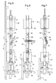
figures 1, 2 et3 sont des vues partielles de profil d'une serrure selon un premier mode de réalisation, respectivement en position verrouillée, en position d'attente et en position déverrouillée, - la
figure 4 est une vue partielle de cette serrure en coupe selon un plan horizontal, - les
figures 5, 6 et 7 sont des vues partielles de profil d'une serrure selon un deuxième mode de réalisation, respectivement en position verrouillée, en position d'attente et en position déverrouillée. - La serrure ici décrite est destinée à équiper un bâti fixe enchâssé dans une ouverture d'une paroi et sur lequel est articulé un panneau formant un battant, par exemple une porte. La serrure est en l'espèce agencée pour former une serrure du type à encastrer qui est disposée dans un logement pratiqué dans un côté du bâti opposé à l'articulation du panneau. La serrure peut également être montée dans un logement ménagé sur un chant du panneau.
- En référence aux
figures 1 à 4 , la serrure conforme au premier mode de réalisation de l'invention comprend une têtière 1 allongée sur une face 2 de laquelle sont montés un pêne 3 pour coulisser perpendiculairement à la têtière 1 entre une position verrouillée (représentée à lafigure 1 ) en saillie d'une face opposée 4 de la têtière et une position dégagée (représentée à lafigure 3 ) escamotée dans la têtière 1, et un dispositif, généralement désigné en 5, de blocage du pêne 3 en position verrouillée. La têtière 1 comprend ici une platine ayant des faces opposées formant les faces 2 et 4 et des corbeaux en saillie de la face 2 pour supporter les différents éléments de la serrure : la têtière est ici réalisée d'une seule pièce par moulage. Un boîtier 6 est fixé sur la face 2 de la têtière 1 pour recouvrir le pêne 3 et le dispositif de blocage 5. - Le dispositif de blocage 5 comprend une genouillère 7, comportant deux biellettes articulées l'une à l'autre, qui est montée derrière le pêne 3 et relie le pêne 3 à la têtière 1. La genouillère 7 possède un état de blocage dans lequel la genouillère 7 est arc-boutée et maintient le pêne 3 en position verrouillée et un état plié dans lequel la genouillère 7 est pliée et le pêne 3 est dans sa position dégagée. Dans l'état de blocage, les biellettes s'étendent sensiblement le long de la direction de coulissement, le point d'articulation des biellettes entre elles étant en appui contre une butée 8 située d'un côté d'un axe d'alignement 9 des biellettes opposé au point d'articulation de la genouillère 9 lorsque cette dernière est dans son état plié. La butée 8 est ici formée par un téton d'une vis engagée dans la têtière 1 de manière à permettre par vissage ou dévissage un réglage de la position de la butée 8 par rapport à l'axe d'alignement 9 des biellettes. Le point d'articulation de la genouillère 7 au pêne 3 et le point d'articulation de la genouillère 7 à la têtière 1 sont alignés sur l'axe de coulissement 9.
- Le dispositif de blocage comprend un organe d'actionnement de la genouillère 7 entre son état de blocage et un état de déblocage dans lequel le pliage de la genouillère 9 a été amorcé en décollant le point d'articulation des biellettes de la butée 8 et en amenant le point d'articulation des biellettes du côté de l'axe d'alignement 9 opposé à la butée 8. La genouillère 7 dans l'état de déblocage autorise un déplacement du pêne 3 entre sa position dégagée et une position d'attente (représentée à la
figure 2 ) intermédiaire entre la position dégagée et la position verrouillée. - L'organe d'actionnement comprend un électroaimant 10 linéaire qui est monté sur la têtière 1 et a un noyau coulissant 11 s'étendant selon une direction sensiblement perpendiculaire à l'axe de coulissement 9 du pêne 3. L'électroaimant 10 est un électroaimant simple effet qui est agencé pour amener la genouillère 7 dans son état de blocage lorsqu'il est alimenté en énergie électrique et dont le noyau 11 a une course utile de 5 mm environ (le noyau 11 peut cependant être déplacé au-delà de sa course utile lorsque l'électroaimant 10 n'est pas alimenté).
- Le noyau coulissant 11 a son extrémité inférieure dont est solidaire une chape 16 qui comprend une portée cylindrique externe reçue à coulissement dans un logement de la têtière 1 et qui est articulée à une extrémité 19.1 d'un coulisseau 19 ayant, à l'opposé, une extrémité 19.2 reliée au point d'articulation des biellettes de la genouillère 7.
- Le dispositif d'actionnement comprend également un dispositif de rappel élastique rappelant le pêne 3 vers sa position intermédiaire depuis sa position dégagée. Le dispositif de rappel comprend ici un ressort 12 monté autour du noyau coulissant 11 de l'électroaimant 10 pour prendre appui, d'une part, sur la têtière 1 et, d'autre part, sur une rondelle 17 destinée à coopérer avec un épaulement formé sur la chape 16 solidaire du noyau coulissant 11.
- La serrure comprend en outre un organe d'actionnement supplémentaire comportant un cylindre 13 (schématisée en trait mixte double) solidaire de la face 2 de la têtière 1 et équipé d'un panneton mobile 14 pour coopérer avec une clenche 15 aménagée dans un guide de clenche 20 ayant une extrémité reçue à coulissement dans un logement de la têtière 1 et une extrémité opposée reliée à la chape. La manoeuvre du panneton mobile 14 permet de déplacer le noyau coulissant 11 entre ses positions de blocage et de déblocage de la genouillère 7. Le cylindre 13 est destiné à coopérer de façon classique avec une clé agencée pour permettre la manoeuvre du panneton mobile 14. On notera que le coulisseau 19 a une forme légèrement courbée pour éviter que le cylindre n'entrave le mouvement du coulisseau.
- Le dispositif d'actionnement comprend enfin un ressort 24 monté autour du guide de clenche 20 entre la têtière 1 et la chape 16 pour rappeler élastiquement le pêne 3 dans sa position intermédiaire depuis sa position verrouillée.
- La serrure comprend également une gâche 21 destinée à être montée sur le battant en regard du pêne 3 pour recevoir celui-ci lorsque le battant est fermé et le pêne 3 est au voisinage de la position verrouillée. La gâche 21 et le pêne 3 sont conformés pour que le pêne 3 soit coulant entre la position intermédiaire et la position dégagée. La gâche 21 comporte à cette fin un coulisseau 23 comportant un creux de réception d'une extrémité libre 18 du pêne 3. Le creux de réception comporte des surfaces 22 disposées en V à 90° l'une par rapport à l'autre. L'extrémité libre 18 du pêne 3 est biseautée et présente elle aussi deux faces à 90° l'une de l'autre. Les surfaces 22 sont agencées pour coopérer avec l'extrémité libre 18 du pêne 3 et l'amener à la manière d'une came de sa position intermédiaire vers sa position déverrouillée lors d'un déplacement du pêne 3 selon une direction sensiblement perpendiculaire à sa direction de coulissement dans un sens d'ouverture de la porte. Le coulisseau 23 est monté dans la gâche 21 pour coulisser parallèlement à la direction de coulissement en étant rappelé élastiquement vers une ouverture d'entrée de l'extrémité libre 18 du pêne 3 dans la gâche 21. Le coulisseau 23 est ici en une seule pièce de polyéthylène téréphtalate incorporant un lubrifiant solide.
- Lorsque la porte est fermée et l'électroaimant 10 est alimenté, le pêne 3 est maintenu en position verrouillée par la genouillère 7 maintenue dans son état de blocage par l'électroaimant 10 (
figure 1 ). L'extrémité libre 18 du pêne 3 est reçu dans le creux de réception ménagé dans le coulisseau 23. - La porte peut être ouverte en appuyant sur un bouton de commande, ou un clavier à code, qui coupe temporairement l'alimentation de l'électroaimant 10 qui amène la genouillère 7 dans son état de déblocage et donc le pêne 3 dans sa position intermédiaire d'attente (
figure 2 ). Un effort de déplacement du battant de sa position fermée vers sa position ouverte exercé par l'utilisateur provoque alors un déplacement latéral de l'extrémité libre 18 du pêne 3 par rapport à une des surfaces 22 qui va déplacer le pêne 3 de sa position intermédiaire d'attente vers sa position dégagée permettant l'ouverture du battant (figure 3 ). Ce coulissement du pêne 3 provoque le pliage de la genouillère 7 entraînant un coulissement vertical du coulisseau 19, de la chape 16, et du noyau 11. Au cours de ce coulissement la chape 16 vient déplacer la rondelle 17 vers l'électroaimant 10 en provoquant la compression du ressort 12. - Le ressort 12 ramène le pêne 3 vers sa position intermédiaire d'attente dès que son extrémité libre 18 quitte l'appui de la gâche 21. L'arrivée en position intermédiaire du pêne 3 correspond à l'arrivée de la rondelle 17 en appui contre la têtière 1.
- A la fermeture, l'extrémité libre 18 du pêne 3 rencontre une surface externe 25 de la gâche 21 qui est inclinée et amène le pêne 3 de sa position intermédiaire d'attente vers sa position dégagée pour permettre l'introduction de l'extrémité libre 18 du pêne 3 dans la gâche 21.
- L'électroaimant 10 déplace à nouveau le pêne 3 dans sa position verrouillée sous l'effet d'un détecteur de fermeture de la porte ou d'une temporisation rétablissant l'alimentation de l'électroaimant 10. Le déplacement du pêne est obtenu par un déplacement du noyau entraînant la chape 16 et coulisseau 11 pour verrouiller la genouillère 7 dans son état de blocage en comprimant le ressort 24.
- La porte peut être ouverte également en actionnant le panneton mobile 14 au moyen d'une clé engagée dans le cylindre 13. La rotation du panneton commande également la coupure de l'alimentation de l'électroaimant 10.
- En cas de coupure accidentelle de l'alimentation de l'électroaimant 10, le pêne 3 est en position intermédiaire permettant l'ouverture et la fermeture de la porte mais pas son verrouillage. Cette serrure est dite à rupture.
- Les éléments identiques ou analogues à ceux précédemment décrits porteront une référence numérique identique dans la description qui suit du deuxième mode de réalisation.
- Dans le deuxième mode de réalisation représenté aux
figures 5 à 7 , l'organe d'actionnement comprend comme précédemment un électroaimant 10 avec un noyau 11, une rondelle 17, un ressort 12, une chape 16, et un coulisseau 19 montés comme dans le premier mode de réalisation sur la têtière 1 pour agir sur une genouillère 7. - Au contraire du premier mode de réalisation, l'organe d'actionnement est dépourvu de ressort rappelant élastiquement le coulisseau 19 dans une position correspondant à la position intermédiaire du pêne 3. Ce ressort est remplacé dans le deuxième mode de réalisation par un actionneur électromagnétique 30 coaxial à l'actionneur électromagnétique 10 et monté en opposition avec ce dernier.
- L'actionneur électromagnétique 30 est un électroaimant linéaire comportant un noyau 31 s'étendant dans le prolongement du noyau 11 et relié au noyau 11 par une bielle 32. Le noyau 31 est relié à la bielle 32 par l'intermédiaire d'un axe 33 solidaire du noyau 31 et reçu à coulissement dans une lumière allongée 34 ménagée dans la bielle 32 parallèlement à la direction de coulissement des noyaux 11, 31. La lumière 34 a une dimension parallèlement à la direction de coulissement des noyaux 11, 31 qui est sensiblement égale à la dimension séparant les positions du noyau 11 respectivement lorsque la genouillère est dans sont état de déblocage et le pêne 3 est en position intermédiaire et lorsque la genouillère 7 est dans son état plié et le pêne 3 est en position dégagée.
- Les électroaimants 10, 30 sont ainsi montés pour actionner la genouillère 7 respectivement vers son état de blocage pour verrouiller le pêne 3 et vers son état de déblocage pour déverrouiller le pêne 3. La lumière 34 permet au noyau 11 de se déplacer au-delà de sa course utile lorsque le pêne 3 est enfoncé dans sa position dégagée à l'ouverture ou à la fermeture de la porte.
- Au contraire, du premier mode de réalisation, lorsque les électroaimants 10, 30 ne sont pas alimentés, ils maintiennent la genouillère respectivement dans son état de verrouillage et dans son état déverrouillé respectivement.
- L'organe d'actionnement comprend en outre un dispositif de maintien élastique de la bielle 32 dans sa position correspondant à la position intermédiaire du pêne 3 de telle manière qu'en l'absence d'alimentation électrique des actionneurs des vibrations, chocs ou autres perturbations de ce type ne viennent provoquer un déplacement de la bielle dans sa position de verrouillage. Le dispositif de maintien élastique comprend un positionneur formé d'un cavalier en U 35 qui est monté sur la têtière 1 pour pivoter autour d'un axe perpendiculaire à la direction de coulissement de la bielle 32 et qui délimite une fente recevant à coulissement un doigt 36 solidaire de la bielle 32. Un ressort de compression 37 est intercalé entre le fond de la fente et le doigt 36.
- Lorsque la bielle 32 est dans une position médiane correspondant à la position intermédiaire du pêne 3 (voir
figure 6 ), le doigt 36 et l'axe de pivotement du cavalier 35 sont alignés sur une direction perpendiculaire à la direction de coulissement de la bielle 32 de sorte que le ressort de compression 37 est dans un état de compression maximale. - Lorsque le coulisseau est déplacé de cette position médiane vers sa position de verrouillage ou sa position de déverrouillage, le ressort 37 se détend et écarte le doigt 36 et le cavalier 35 facilitant le déplacement de la bielle 32.
- Dans le deuxième mode de réalisation, il est possible de prévoir un actionnement par cylindre et panneton comme dans le premier mode de réalisation.
- Bien entendu, l'invention n'est pas limitée au mode de réalisation décrit et on peut y apporter des variantes de réalisation sans sortir du cadre de l'invention tel que défini par les revendications.
- La serrure de l'invention peut être utilisée en position horizontale ou verticale.
- La genouillère peut comprendre une seule paire de biellettes ou deux paires de biellettes disposées en parallèle l'une de l'autre. Les biellettes peuvent être accolées ou non.
Claims (9)
- Serrure comportant une têtière (1) sur laquelle sont montés un pêne (3) coulissant entre une position verrouillée en saillie de la têtière et une position dégagée en retrait de la position verrouillée, et des moyens de blocage du pêne en position verrouillée, la serrure comprenant également une gâche (21) destinée à être montée en regard du pêne pour recevoir celui-ci lorsque le pêne est au voisinage de la position verrouillée, caractérisée en ce que les moyens de blocage comprennent une genouillère (7) qui relie le pêne à la têtière et possède un état d'arc-boutement dans lequel la genouillère maintient le pêne en position verrouillée et un état de déblocage dans lequel la genouillère autorise un déplacement du pêne entre sa position dégagée et une position intermédiaire entre la position dégagée et la position verrouillée, en ce que les moyens de blocage comprennent au moins un organe d'actionnement (10, 13) de la genouillère entre ses deux états et en ce que la gâche (21) et le pêne sont conformés pour que le pêne soit coulant entre la position intermédiaire et la position dégagée, un dispositif de rappel élastique rappelant le pêne vers sa position intermédiaire.
- Serrure selon la revendication 1, dans laquelle l'organe d'actionnement (10) comprend un électroaimant linéaire ayant un noyau (11) coulissant s'étendant selon une direction sensiblement perpendiculaire à la direction de coulissement du pêne (3).
- Serrure selon la revendication 2, dans laquelle l'électroaimant (10) est un électroaimant simple effet agencé pour maintenir la genouillère (7) dans son état de blocage lorsqu'il est alimenté en énergie électrique.
- Serrure selon la revendication 2, dans laquelle le dispositif de rappel comprend un ressort (12) monté pour agir sur la genouillère (7).
- Serrure selon la revendication 4, dans laquelle le ressort (12) s'étend autour du noyau (11) coulissant de l'électroaimant (10).
- Serrure selon la revendication 1, dans laquelle l'organe d'actionnement comprend deux électroaimants (10,30) coaxiaux qui sont montés en opposition et ont un respectivement un premier noyau (11) coulissant et un deuxième noyau coulissant s'étendant selon une direction sensiblement perpendiculaire à la direction de coulissement du pêne (3), le premier noyau coulissant actionnant directement la genouillère et le deuxième noyau coulissant actionnant le premier noyau coulissant, les électroaimants étant montés pour actionner la genouillère (7) respectivement vers son état de blocage et vers son état de déblocage, le dispositif de rappel élastique agit sur au moins le premier noyau coulissant pour rappeler celui-ci dans des positions correspondant respectivement à l'état de blocage de la genouillère et un état plié de la genouillère dans lequel la genouillère maintient le pêne en position dégagée.
- Serrure selon la revendication 6, dans laquelle l'organe d'actionnement comprend un dispositif de maintien élastique (35) des noyaux dans leur position correspondant à la position intermédiaire du pêne (3).
- Serrure selon la revendication 2 ou la revendication 6, dans laquelle l'organe d'actionnement comprend un cylindre (13) comportant un panneton (14) de déplacement du noyau coulissant dans un sens de déblocage de la genouillère (7).
- Serrure selon la revendication 1, dans laquelle la gâche (21) comporte au moins une surface de came (22) pour coopérer avec le pêne (3) et l'amener de sa position intermédiaire vers sa position déverrouillée lors d'un déplacement du pêne selon une direction sensiblement perpendiculaire à sa direction de coulissement, la surface étant solidaire d'un coulisseau monté dans la gâche pour coulisser parallèlement à la direction de coulissement en étant rappelé élastiquement vers une ouverture d'entrée du pêne dans la gâche.
Applications Claiming Priority (1)
| Application Number | Priority Date | Filing Date | Title |
|---|---|---|---|
| FR0902019A FR2944826B1 (fr) | 2009-04-24 | 2009-04-24 | Serrure a pene coulant verrouillable par genouillere |
Publications (1)
| Publication Number | Publication Date |
|---|---|
| EP2246505A1 true EP2246505A1 (fr) | 2010-11-03 |
Family
ID=41314705
Family Applications (1)
| Application Number | Title | Priority Date | Filing Date |
|---|---|---|---|
| EP10160509A Withdrawn EP2246505A1 (fr) | 2009-04-24 | 2010-04-20 | Serrure a pêne coulant verrouillable par genouillère |
Country Status (2)
| Country | Link |
|---|---|
| EP (1) | EP2246505A1 (fr) |
| FR (1) | FR2944826B1 (fr) |
Families Citing this family (1)
| Publication number | Priority date | Publication date | Assignee | Title |
|---|---|---|---|---|
| CN104847184B (zh) * | 2015-05-19 | 2017-03-15 | 广州御银自动柜员机技术有限公司 | 一种安全锁结构 |
Citations (4)
| Publication number | Priority date | Publication date | Assignee | Title |
|---|---|---|---|---|
| FR2536108A1 (fr) * | 1982-11-17 | 1984-05-18 | Lambert Christian | Serrure de securite pour porte principale d'un local, tel qu'un appartement |
| FR2656909A1 (fr) | 1990-01-05 | 1991-07-12 | Charles Gerard | Mecanisme transferant un deplacement d'une piece a une autre et serrure le comprenant. |
| FR2816977A1 (fr) * | 2000-11-22 | 2002-05-24 | Gerard Charles | Serrure a commande electrique |
| WO2005090718A1 (fr) * | 2004-03-24 | 2005-09-29 | Vision Systems Aeronautics | Systeme d’ouverture/fermeture d’une porte permettant l’acces entre la cabine passagers et le cockpit d’un avion |
-
2009
- 2009-04-24 FR FR0902019A patent/FR2944826B1/fr not_active Expired - Fee Related
-
2010
- 2010-04-20 EP EP10160509A patent/EP2246505A1/fr not_active Withdrawn
Patent Citations (4)
| Publication number | Priority date | Publication date | Assignee | Title |
|---|---|---|---|---|
| FR2536108A1 (fr) * | 1982-11-17 | 1984-05-18 | Lambert Christian | Serrure de securite pour porte principale d'un local, tel qu'un appartement |
| FR2656909A1 (fr) | 1990-01-05 | 1991-07-12 | Charles Gerard | Mecanisme transferant un deplacement d'une piece a une autre et serrure le comprenant. |
| FR2816977A1 (fr) * | 2000-11-22 | 2002-05-24 | Gerard Charles | Serrure a commande electrique |
| WO2005090718A1 (fr) * | 2004-03-24 | 2005-09-29 | Vision Systems Aeronautics | Systeme d’ouverture/fermeture d’une porte permettant l’acces entre la cabine passagers et le cockpit d’un avion |
Also Published As
| Publication number | Publication date |
|---|---|
| FR2944826B1 (fr) | 2011-05-27 |
| FR2944826A1 (fr) | 2010-10-29 |
Similar Documents
| Publication | Publication Date | Title |
|---|---|---|
| EP0959206B1 (fr) | Serrure de porte de véhicule automobile à condamnation électrique | |
| FR2639668A1 (fr) | Serrure electromecanique de porte | |
| EP1188889B1 (fr) | Véhicule automobile avec une porte battante et une porte coulissante indépendantes l'une de l'autre | |
| EP0953094B1 (fr) | Serrure encastree | |
| EP0978609A1 (fr) | Serrure de porte à assistance électrique | |
| BE1020832A3 (fr) | Dispositif de commande de verrouillage pour vantail. | |
| FR2775717A1 (fr) | Dispositif d'ouverture/fermeture d'un ouvrant, notamment pour vehicule automobile | |
| EP2526244B1 (fr) | Caisse de véhicule, et dispositif de verrouillage de la porte en position de fermeture | |
| EP0292361B1 (fr) | Serrure comportant un mécanisme de déverrouillage à fonctionnement électrique | |
| FR2749343A1 (fr) | Dispositif de fermeture de porte a commande electrique | |
| FR2660689A1 (fr) | Ensemble de manóoeuvre pour verrou de second battant de porte. | |
| EP2246505A1 (fr) | Serrure a pêne coulant verrouillable par genouillère | |
| FR2816977A1 (fr) | Serrure a commande electrique | |
| FR2778940A1 (fr) | Serrure de porte de vehicule automobile a decondamnation electrique et ouverture electrique | |
| FR2695426A1 (fr) | Serrure à commande électrique à distance, destinée à équiper une porte. | |
| FR2861789A1 (fr) | Serrure anti-panique multipoint reversible | |
| EP0312654B1 (fr) | Serrure de sécurité | |
| EP0360696B1 (fr) | Dispositif de verrouillage d'une porte à deux battants | |
| FR2814190A1 (fr) | Mecanisme de manoeuvre de porte | |
| EP1458945B1 (fr) | Serrure electrique | |
| EP2578778A1 (fr) | Dispositif pour fermer une ouverture de construction comportant des moyens d'assistance au verrouillage et au déverrouillage de l'ouvrant | |
| FR2697278A1 (fr) | Dispositif de verrouillage/déverrouillage pour portail à deux battants, et portail équipé d'un tel dispositif. | |
| FR2744752A1 (fr) | Dispositif de verrouillage perfectionne, notamment d'une issue de secours | |
| FR2923250A1 (fr) | Systeme de verrouillage d'un systeme d'ouverture/fermeture comprenant un element de verrouillage pivotant sur un panneau mobile du systeme d'ouverture/fermeture | |
| FR3097581A1 (fr) | Boitier de serrure à verrouillage automatique |
Legal Events
| Date | Code | Title | Description |
|---|---|---|---|
| PUAI | Public reference made under article 153(3) epc to a published international application that has entered the european phase |
Free format text: ORIGINAL CODE: 0009012 |
|
| AK | Designated contracting states |
Kind code of ref document: A1 Designated state(s): AT BE BG CH CY CZ DE DK EE ES FI FR GB GR HR HU IE IS IT LI LT LU LV MC MK MT NL NO PL PT RO SE SI SK SM TR |
|
| AX | Request for extension of the european patent |
Extension state: AL BA ME RS |
|
| 17P | Request for examination filed |
Effective date: 20110128 |
|
| GRAP | Despatch of communication of intention to grant a patent |
Free format text: ORIGINAL CODE: EPIDOSNIGR1 |
|
| RIC1 | Information provided on ipc code assigned before grant |
Ipc: E05B 47/00 20060101AFI20120625BHEP Ipc: E05C 9/18 20060101ALI20120625BHEP |
|
| STAA | Information on the status of an ep patent application or granted ep patent |
Free format text: STATUS: THE APPLICATION IS DEEMED TO BE WITHDRAWN |
|
| 18D | Application deemed to be withdrawn |
Effective date: 20121213 |