EP2245973B1 - Système de sous-construction pour bacs de douche et sols de douche - Google Patents
Système de sous-construction pour bacs de douche et sols de douche Download PDFInfo
- Publication number
- EP2245973B1 EP2245973B1 EP10004271.2A EP10004271A EP2245973B1 EP 2245973 B1 EP2245973 B1 EP 2245973B1 EP 10004271 A EP10004271 A EP 10004271A EP 2245973 B1 EP2245973 B1 EP 2245973B1
- Authority
- EP
- European Patent Office
- Prior art keywords
- plate
- height
- shower
- support
- base plate
- Prior art date
- Legal status (The legal status is an assumption and is not a legal conclusion. Google has not performed a legal analysis and makes no representation as to the accuracy of the status listed.)
- Active
Links
Images





Classifications
-
- A—HUMAN NECESSITIES
- A47—FURNITURE; DOMESTIC ARTICLES OR APPLIANCES; COFFEE MILLS; SPICE MILLS; SUCTION CLEANERS IN GENERAL
- A47K—SANITARY EQUIPMENT; ACCESSORIES THEREFOR, e.g. TOILET ACCESSORIES
- A47K3/00—Baths; Showers; Appurtenances therefor
- A47K3/16—Devices for fastening baths to floors or walls; Adjustable bath feet ; Lining panels or attachments therefor
-
- A—HUMAN NECESSITIES
- A47—FURNITURE; DOMESTIC ARTICLES OR APPLIANCES; COFFEE MILLS; SPICE MILLS; SUCTION CLEANERS IN GENERAL
- A47K—SANITARY EQUIPMENT; ACCESSORIES THEREFOR, e.g. TOILET ACCESSORIES
- A47K3/00—Baths; Showers; Appurtenances therefor
- A47K3/16—Devices for fastening baths to floors or walls; Adjustable bath feet ; Lining panels or attachments therefor
- A47K3/17—Adjustable bath feet
-
- A—HUMAN NECESSITIES
- A47—FURNITURE; DOMESTIC ARTICLES OR APPLIANCES; COFFEE MILLS; SPICE MILLS; SUCTION CLEANERS IN GENERAL
- A47K—SANITARY EQUIPMENT; ACCESSORIES THEREFOR, e.g. TOILET ACCESSORIES
- A47K3/00—Baths; Showers; Appurtenances therefor
- A47K3/28—Showers or bathing douches
- A47K3/40—Pans or trays
Definitions
- the present invention relates to a substructure system as used in the sanitary area.
- Bathtubs and in particular shower trays or only shower trays for, for example, floor-level showers are placed on a support frame, for example.
- This support frame allows the shower base to be tiled to be set appropriately, while at the same time making it easier to install and adapt the drain or siphon.
- These sound bridges or the contact surfaces of the shower base on the support frame can simultaneously represent cold bridges that cause uncomfortably cold foot contact via the tiled shower base.
- the different materials used in conventional substructure systems have different material densities and properties, especially with regard to moisture absorption and expansion coefficient under changing temperature conditions. These different material densities and the different temperature properties in turn cause different shrinkage behavior, which and can cause joint damage or leaks.
- granulate fillings or fillings which serve to form slopes or to fill the cavities around the supporting frame between in-situ concrete and shower base with appropriate material, can trickle out with insufficient compaction, which in turn can lead to subsidence and damage .
- Another disadvantage is the fact that the known substructure systems no longer allow the leakage control of the drain or siphons to be checked, either immediately after installation has been completed or later during operation. After the previously described laying or pouring of a gradient concrete or the compaction of the underbody granulate, the drain or the siphon are no longer accessible.
- Another disadvantage is that the concrete, the mortar and the granulate binder require drying times, postpone the follow-up work and are an overall extension compared to modern drywall construction with short construction periods and minimized execution risk according to today's professional knowledge and expected professional responsibility.
- floor-level showers are also implemented with shower base elements.
- These shower base elements are predominantly foam panels with an integrated slope, which are covered with a sealing slurry and reinforced with a mesh fabric.
- the required installation height or required from case to case is achieved with additional panel supports or by stuffing with different materials.
- the water drainage (siphon and drain pipe) is installed before the shower base element is placed.
- the drainage channel or a drain housing or siphons are connected via a socket, which can be plugged or screwed.
- Foam sheets are also not stable against mechanical loads and, when new and with aging, are subject to a sometimes considerable shrinkage behavior, which in turn can result in board and joint damage.
- the height adjustment of the top edge of the shower base element to the top edge of the sub-floor or screed is cumbersome and time-consuming in the known substructure systems. It is done by placing additional foam sheets of variable thickness or by filling them with granules, sand or similar. Once the height ratio has been reached with a lot of effort, it can hardly be corrected afterwards, which is necessary, for example, if ceramic floor slabs or tiles with a different thickness than before are to be used in a renovation.
- the open-cell foam structure does not allow inspection openings to be made. It is also not possible to cut recesses or to carry out subsequent mechanical processing because this would damage the reinforcement or the sheathing of the foam panels.
- the foam sheets are thus made in advance according to the specified fixed dimensions.
- the drainage channel or the drainage housing must be installed in this or in parts of it before laying the shower base element.
- the drainage connection of the drainage channel or the drainage housing is made via a sleeve.
- the siphon and the drain pipe must be positioned accurately before the shower floor element is installed and secured against displacement.
- the prior art also discloses combinations of support frames with shower base elements in which the support frame can be adjusted in height by means of threaded feet.
- the support frame is installed, on which the shower base element is placed after setting the previously measured height ratio.
- the water outlet is connected via the shower channel or the drain housing via a sleeve.
- a disadvantage of these combinations of a support frame and a shower base element is that the height adjustment and, at the same time, the necessary leveling of the support frame is cumbersome and time-consuming.
- a setting position for the shower base element is reached only after repeated measuring and leveling processes, which should also be correct right away when the shower base element is placed on it.
- the installation height of floor-level showers depends on the height of the subfloor or screed and usually varies between 40 and 300 mm. Covering this entire adjustment range of 260 mm cannot always be guaranteed by the threaded feet or at least cannot be economical, so that it may prove disadvantageous to have to provide threaded feet that correspond to the special conditions on site. This is also a possible source of errors.
- the drain channel or the drain housing must be installed in the shower base element before laying it.
- the water-carrying connection of the drainage channel or the drainage housing to the siphon is again via a sleeve. This means that the siphon and the drain pipe must be positioned precisely before installing the shower base element and secured against displacement.
- the disclosure DE 100 14 044 A1 discloses a tub support with height-adjustable feet, wherein a substructure system is described with a support device that can be created at an adjustment height with at least one height adjustment with a contact surface for at least one plate.
- the height adjustment has at least one endless threaded rod and the plate has an assembly opening.
- a suitability for a bottomless shower cubicle is not listed in the document.
- German utility model G 93 17 159.5 in turn discloses a support frame for tubs, the frame not only comprising height-adjustable feet, but also swiveling and extending arms. This makes it possible to meet bathtub shapes such as quarter-circle or pentagonal shower trays.
- the Austrian utility model AT 008 143 U1 describes a fastener for a floor drain.
- an endless threaded rod can be operated from above, but the fastening element is not part of a substructure system for tubs or plates floor-level shower cubicle.
- the JP 2002-88839 suggests making the drain body of a drain transparent for inspection purposes or to look for leaks.
- the EP 0 788 755 A1 discloses a tub support which is cast or foamed from foamed plastic. Before the tub is placed on the tub support, the fitter can provide an assembly and inspection opening designed as a slide in a side wall of the tub support.
- the object of the present invention is to provide a substructure system for shower cells which largely avoids the disadvantages described above and is optimized with regard to its later properties in the assembled operating state, but also with regard to its ability to be installed.
- the solution to the problem consists first of all in the arrangement of a shower cell substructure system with a height-adjustable support device with support surfaces on which a support plate or a shower base plate or both can be placed.
- the height adjustment of the substructure system is designed to be more stable than in the case of known support devices and, at the same time, is designed in such a way that it can still be operated from above through at least one mounting hole or through at least one assembly or inspection opening in the plate or the plates, even when the plate or plates are in place.
- This assembly or inspection opening in the support plate is arranged approximately in the center or offset to its edge and is designed and dimensioned such that during assembly, with the support plate already in place or pre-assembled, the height of the upper edge of the support plate corresponds to the height of the upper edge of the sub-floor or screed or finished floor can be set flush.
- This is guaranteed according to the invention in that the elements with which the height can be adjusted - for example with threaded feet - are accessible through the mounting or inspection opening when the support plate is in place. This gives the essential advantage that no previous measurements and any test placements of the support plate have to be carried out. Leakage checks can also be carried out on the drainage system, both during assembly and during later operation.
- the support plate can optionally represent the shower base plate to be tiled later, or a separate shower base plate can be placed on the support plate and fastened, which can be adapted in the same way to the height of the upper edge of the underlay or screed or finished floor.
- a further embodiment variant according to the invention provides that the support frame is integrated in the support plate, which is also the top shower base plate or in the support plate, on which a separate shower base plate is placed.
- the support plate or the shower base plate itself forms the frame on which the elements with which the height can be adjusted are arranged, or other fastening and positioning elements according to the invention, which are described below to be discribed.
- the support plate or the shower base plate preferably has an underside, which is flat and corresponds to the horizontal in the assembled state.
- the top of the support plate or the shower base plate is preferably equipped with at least one surface that is at an angle to the horizontal.
- a single surface forms an inclined plane on which the water flows into a laterally arranged shower channel or into a drain housing.
- Another possible embodiment variant forms the slopes described in the shower base plate itself, be it whether the support device consists of a support plate, which is preferably planar in this case, and a shower base plate placed on top or only a shower base plate.
- the support plate forms the required slope and the shower base plate can thus be a normal, flat on both sides (top and bottom parallel to each other).
- design variants are also feasible in which an overall gradient results from the addition of a support plate gradient and a shower base slab results.
- a further design variant of the support plate or the shower base plate provides a normal, uniformly strong plate, which, however, is inclined as a whole by means of supports of different heights - preferably integrated in the support plate or shower base plate.
- This embodiment variant or else one in which the underside of the support plate or the shower base plate forms at least two inclined surfaces, so that the cross section of the support plate tapers approximately in the middle, can be advantageous with regard to a free arrangement of the drainage system.
- design variants of the support plate or the shower base plate disclose an underside lying horizontally in the assembled state or at least supports which form horizontally lying contact surfaces in the assembled state.
- design variants of support plates or shower base plates are also hereby disclosed in which the underside or the support surfaces are inclined or concave and this results in more extensive and more powerful adjustment options, for example with threaded feet, which are preferably both on their lower and on their upper Stand in ball joints at the end.
- an inexpensive variant of a substructure system can be easily implemented, in which only a single direction of inclination towards a laterally arranged shower channel or a laterally arranged drain housing is provided. Due to the fact that the ball joints hold the support plate or the shower base plate at the side, a conventional plate that is flat on both sides can be raised or raised on one side without an integrated gradient. Basically, the same effect can also be achieved with threaded mounts or holders for the threaded feet that the desired Have inclination angles from the outset. This means that the threaded feet are inclined when the support plate or shower base plate is horizontal.
- the support device preferably has a plurality of height adjustments or novel thread feet, each of which is height-adjustable with an endless threaded rod.
- the endless threaded rods are in shoes or relatively flat buffer disks, which are preferably made of a soft and low-noise material - for example rubber.
- the endless threaded rod is preferably mounted in the shoe with a ball joint, so that rotations of the endless threaded rod are not stopped early by contact friction of the shoe on the in-situ concrete. It is equipped with a square or key holder for easy rotation of the endless threaded rod.
- the key holder can in principle also be arranged on the upper head of the endless threaded rod, for example for an Allen key or Torx key, and can be reached through a correspondingly positioned mounting hole in the support plate and / or the shower base plate.
- these so-called endless threaded rods have the decisive advantage over arrangements from the prior art that they are significantly larger Operate the adjustment height.
- the arrangements according to the prior art namely disclose a threaded rod which is fixed with its upper end fixed below the desired support point in the supporting frame and thus provides height adjustability which results solely from how far a threaded foot can be screwed down from the fixed threaded rod without the thread foot becomes unstable.
- the maximum screw-on dimension can at best be equal to the total height of the neck of the threaded foot minus the height of a threaded foot nut.
- the height adjustability of a support frame according to the invention is realized differently in that on the one hand the (endless) threaded rod is arranged offset next to the support surface of the support frame or the support device and on the other hand the overall length of the support frame or the support device clearly exceeds.
- it is not a threaded foot with a nut that is rotated on a fixedly arranged threaded rod, but rather the (endless) threaded rod in a fixedly arranged nut. Or also in a thread that is cut directly into a hole in the bracket.
- a screwed base foot is present, quasi in accordance with the state of the art, which, however, remains screwed in as far as possible and is not used for height adjustment.
- the base foot can therefore be designed to be significantly flatter than a buffer disk.
- the upper attachment point or rather the force application point of the threaded foot according to the invention is no longer located on the upper head of the threaded rod, but in an L-shaped holder or in a nut fixedly arranged on this holder.
- the upper force application point of the threaded foot according to the invention thus moves over its entire length due to rotations of the endless threaded rod.
- the height adjustment according to the invention is thus characterized by a significantly greater adjustability with greater stability, because by placing the upper force application point in the fixed nut on the holder (and no longer in a nut arranged in the threaded base itself), only two force application points occur .
- the upper force application point is the nut itself or the bracket and the lower force application point is the lower end of the endless threaded rod.
- the endless threaded rod can be locked with a lock nut to the fixed nut or the threaded hole. Then the protruding length of the endless threaded rod capped with a cutting disc or special pliers.
- the endless threaded rods are preferably available from the outset in a length that guarantees an adjustment height for the maximum usual floor or screed thicknesses or more. An exchange or even a subsequent delivery of threaded rods, even with underlay or screed thicknesses, which are the usual maximum, is excluded from the outset.
- the endless threaded rod is preferably made of a plastic that has a low sound transmission, in any case less than steel.
- the plastic of the endless threaded rods is preferably glass or carbon fiber reinforced.
- the endless threaded rod is arranged in the direction of its upper end in a holder which is fastened to the supporting frame or the supporting device, for example by being welded, screwed or glued on.
- the holder can be arranged both on the support frame, but also on the support plate or on the shower base plate.
- the holder is screwed for receiving the endless threaded rod in a fixed nut, a so-called rivet nut or a threaded sleeve arranged in a press fit, or only in a threaded bore.
- This holder is L-shaped according to the invention, so that one leg of the L can be attached to a vertical surface of the support frame or the support plate or the shower base plate.
- the other leg of the L can optionally be arranged flush with the top edge of the support frame or the top edge of the support plate or the top edge of the shower base plate or flush with the bottom edge of the support frame or the bottom edge of the support plate or the bottom edge of the shower base plate. This allows mounting plates of different thicknesses to be attached to the bracket be put on. Even particularly thin ones, which use the cost-intensive material from which they are made sparingly, preferably also with recessed contact surfaces or blind holes or recesses.
- the holder is quasi double L-shaped as two Ls connected to a web.
- a mounting plate is also conceivable, which is formed from four Ls and a web connecting them.
- the four Ls can also be formed into one or more round walls.
- C-shaped rails are also possible as web supports.
- This web holder can, like the L-shaped holder described above, be fastened to the support frame, or else directly to the support plate or the shower base plate, by screwing or preferably gluing. In the case of gluing, the adhesive surfaces of the web holder are preferably equipped with holes for better contact of the adhesive.
- This web holder provides an approximately centrally arranged or fixable nut on the web, a so-called rivet nut or a press-fitted threaded sleeve or at least one threaded bore into which, as before, the endless threaded rod can be screwed.
- the force application points thus lie in the direct extension of the supporting force that occurs for the support frame, the support plate or the shower base plate. Accordingly, these design variants of a height adjustment according to the invention are further provided according to the invention with a mounting hole which, depending on the arrangement in the support frame, the support plate or the shower base plate, is arranged approximately concentrically with the longitudinal axis of the endless threaded rod.
- the endless threaded rod can be rotated through this mounting hole, preferably by means of a tool holder for a square or an Allen key or Torx key.
- the height of the support device can be adjusted to the desired dimension, or, depending on the design, the height of the upper edge of the support plate or the height of the upper edge of the shower base plate by setting at least three, preferably four such height adjustments to the same height level.
- the mounting hole can then be sealed with a stopper, in particular in the embodiment variant in which the last-described height adjustments are arranged directly on the shower base plate.
- a further embodiment variant of a height adjustment according to the invention both the height adjustment with the L-shaped holder and the last described one with the web holder - provides for a higher degree of height adjustability by arranging the endless threaded rod in a threaded sleeve.
- This threaded sleeve has an external thread that can be screwed into the threaded bore or the nut on the respective holder.
- this threaded sleeve also has a preferably continuous longitudinal bore with an internal thread, into which the endless threaded rod can be screwed.
- the length addition of the usable thread lengths results in a higher adjustability than only by the endless threaded rod alone.
- the threaded sleeve can preferably be secured with lock nuts on the external thread in both screw directions, and the endless threaded rod can also preferably be fixed with a lock nut on the lower end face of the threaded sleeve.
- a lock nut is also possible on the upper face of the threaded sleeve or a so-called grub screw, which is screwed into the internal thread of the threaded sleeve from above and thus fixes the endless threaded rod in the desired height position.
- the bore for receiving the threaded sleeve in the L-shaped holder or the web holder has a larger diameter than the outer diameter of the external thread of the threaded sleeve.
- the latter is thus simply inserted into the bore and fixed with at least one nut on the top of the bore and at least one nut on the bottom of the bore.
- the nuts are preferably each underlaid with a washer and a further washer made of a damping material (for example rubber).
- the threaded sleeve can also form a fixed collar instead of one of the two nuts which they flange onto the web holder, which collar is preferably formed at the upper end of the threaded sleeve.
- This fixed collar can preferably be inserted into the web holder, again preferably into a receptacle that no longer allows the threaded sleeve to be positively rotated and thus the remaining nut can be tightened.
- a configuration variant is further preferred, in which no form-fitting receptacle can produce a possible sound bridge between the threaded sleeve and the web holder, since the fixed collar of the threaded sleeve cannot get direct contact with the inner walls of the web holder.
- a key holder is preferably arranged on the outer diameter of the threaded sleeve.
- This key holder is preferably smaller than the outer diameter of the threaded sleeve or smaller than the external thread of the threaded sleeve and narrower than the nut is high. So the nut can be screwed seamlessly over the key holder.
- the support frame consists of a plurality of support frame elements which can be screwed together.
- a possible basic shape of a support frame according to the invention it forms a square or other basic geometric shapes, the sides of which each consist of a supporting frame element.
- a possible design variant of this basic form provides a web or a bridge on at least one side of the support frame.
- a supporting frame element which previously formed one side of the square, now consists of two shorter supporting frame elements, which are connected to a further supporting frame element above it.
- the web or the bridge thus forms a recess into which the drain housing or the siphon fits in a space-saving manner.
- the support frame optionally has further support frame elements which, in addition to the previously described support frame elements, are arranged in a fixed or pivotable manner on a joint. At least one such pivotally arranged support frame element fulfills the function of an additional, central stabilization of the support plate or shower base plate placed on top. The pivotally arranged support frame element thus also fulfills the function of an additional support or support point for the support plate or the shower base plate, which can advantageously be positioned anywhere within its pivoting radius.
- a further embodiment variant of the support frame connects at least some of the support frame elements or all of the support frame elements with joints. In this way, any basic shapes - depending on the layout of the shower - can be realized.
- the support frame according to the invention furthermore has at least one adjustment element.
- a length adjustment is implemented at least between two support frame elements, for example by a threaded bolt with left-hand external thread at one end and right-hand external thread at another end in corresponding internal threads of the so connected Support frame elements can be rotated.
- this length adjustment can also be implemented with elongated holes or with spacers that can be pushed into one another, which can preferably be fixed with screw fastenings.
- Another, optional design variant of the support frame according to the invention provides an additional adjustment option to the adjustment option described above by means of the threaded bolt or by means of the elongated holes or by means of the displaceable spacers from only one side of the support frame, but also a thread-assisted directional shift of the complete support frame.
- This adjustment option can be used for position corrections of the support frame after the support plate has been placed, preferably in particular in the direction of a vertical connection wall for the shower cell, be it towards this connection wall or away from it.
- the substructure system according to the invention has at least one adjustable and fixable support bracket.
- This support bracket is preferably designed in such a way that it is fastened with an adjustable rail, for example on a horizontal bottom or top of the support frame.
- the support bracket can optionally be attached to the support plate or to the shower base plate as a sliding and fixable positioning plate. By displacing the support bracket in the rail outwards, it can be achieved that a support surface of the support bracket abuts on the lateral boundary surfaces of the underlay floor or screed or a wall, is then fixed and so that the complete support frame is laterally fixed in the underlay floor or Screed is guaranteed.
- the support surface of the support bracket is preferably glued or lined with a sound-insulating material.
- the support bracket can optionally also be arranged on a vertical inside of the support frame or on a vertical edge or a vertical side of the support plate or on a vertical edge or on a vertical side of the shower base plate and thus fixation of the support surface on the floor of the in-situ concrete Reach the support frame against lateral displacement.
- the lateral support surfaces of the support brackets can furthermore be designed as a guide or fastening element which can be inserted into a guide and holding rail of a formwork panel.
- the support brackets can optionally also have a guide surface for inserting the support plate or the support plate and the shower base plate or the shower base plate.
- the support brackets are only used when mounting or when placing the support plate or when placing the support plate and then placing the shower base plate on.
- the support brackets thus only prevent the support frame from shifting, which can occur during installation by placing the support plate or the support plate and the shower base plate or the shower base plate in place by the support brackets after the positioning of the support plate or the support plate and the shower base plate or the shower base plate can be removed again.
- the support brackets can be removed by unscrewing, which is carried out through the assembly or inspection opening.
- the fitter can knock a cone holding the support bracket out of a receptacle holding the cone with a hammer blow.
- the support device according to the invention also has a placement device.
- at least one support plate is arranged on the support frame or on the support plate or on the shower base plate, which is placed on the upper edge of the underfloor or screed (in this case already cast) when the support device is placed.
- the upper edge of the sub-floor or screed is adopted directly as a reference dimension without having to approach this dimension with measurements.
- the laying device further comprises, according to the invention, a spacer, which can be provided in a fixed length, which corresponds, for example, to the thickness of the support plate or the shower base plate - in the event that the top of the support plate represents the shower base or the top of the shower base plate represents the shower base to be tiled.
- the length of the spacer preferably corresponds to the sum of the thickness of the support plate and the thickness of the shower base plate.
- the spacer is optionally designed to be adjustable, for example, it consists of two parts that can be screwed or locked together.
- a corresponding length selection of the spacers or their length adjustment can be used to achieve any desired final dimension for the height of the support device, regardless of the reference dimension.
- the support plate can also be placed on a finished floor that is already tiled and surrounds the shower cell to be erected.
- the support plate of the support device is optionally designed so that it also allows attachment to a vertical end wall or wall. This installation situation is particularly the case when a single shower cell is built, which is enclosed on three sides with walls.
- the support plate and / or the shower base plate are made of a hard material.
- the hard material is preferably a recycling material, for example polyurethane granules, plastic granules, mineral granules, wood fiber granules, etc., which is glued or pressed with a non-water-soluble binder.
- the material is therefore insensitive to moisture, permanently stable in shape, easy to machine and preferably mixed with additives that have an antifungal and antibacterial effect.
- the support plate and / or the shower base plate have integrated recesses for the installation of shower channels or drainage housings. Because of the good mechanical machinability of the material, these cutouts can advantageously also be produced during assembly on site as required.
- the support plate and / or the shower base plate can be formed in one or more parts. You prefer by edge folds or reduced edge thicknesses by milling, so that lateral stability and a minimal installation height are guaranteed.
- the support plate or the shower base plate is preferably equipped with blind holes into which the threaded rods and nuts fit when placed on.
- These blind holes also increase the adjustability to a certain extent, which still ensures a sufficiently firm fit, but they primarily serve to conceal an upper end of the threaded rods and the lock nuts sitting on them.
- a common feature of all design variants is that the upper end of the threaded rod (even after any excess length has been cut off) remains above the support surface of the holder on which the support plate or the shower base plate is placed.
- prefabricated inserts are used that can be used as required.
- the support plate and / or the shower base plate can have prefabricated one- or multi-sided incline designs, depending on the design and position of the drain system.
- the support plate and / or the shower base plate can be partially preassembled so that only adaptation work is required at the place of use.
- the support plate and / or the shower base plate can consist not only of a single plate, but of two or more parts. For example, a part can already be pre-assembled - and connections for the shower channel or drain system pre-assembled at the factory - and only another part of the support plate and / or the shower base plate needs to be placed on site.
- a preferred embodiment variant of a multi-part support plate or shower base plate provides a part which preferably comprises a preassembled drain system.
- This drainage plate part also provides a positive or negative stepped connecting edge with a contact surface for another part of the support plate or shower base plate.
- This latter support plate part of the support plate or shower base plate in turn has a correspondingly negative or positive stepped connecting edge with a corresponding contact surface, so that a positive connection is possible.
- the contact surfaces of the supporting drain plate part and the lay-on plate part are preferably of such a stable shape that no threaded feet are necessary on the connecting edge of the lay-on plate part, because the threaded feet of the supporting drain plate part and the bearing surface take over the carrying of the lay-on plate part.
- the support plate part is designed as a supporting plate and the drainage plate part is placed on it.
- the drain system - be it in the form of a drain housing or in the form of a drain gutter - is tightly and pre-assembled at the factory.
- nuts or threaded sockets are preferably inserted or riveted into the support surface, so that the support plate part can be fastened through appropriately arranged bores, preferably by means of countersunk screws.
- grooves and tongues can also be provided, which additionally positively connect the drain plate part and the lay-on plate part to one another.
- the grooves and tongues can optionally be shaped in such a way that they offer space and corresponding contact surfaces for sealing compound or adhesive.
- the last-described fastening mode is also preferred for a cover plate for the assembly or inspection opening.
- the substructure system according to the invention is particularly suitable for floor-level showers; With appropriate adaptations familiar to a specialist or appropriately dimensioned brackets, however, it is equally suitable as a substructure system for shower trays or also for bathtubs or for whirl bathtubs.
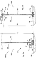
- the Fig. 1a shows a schematic and sectional illustration of a height adjustment 1, as is known from substructure systems according to the prior art and is part of a support device 300a.
- a support frame 2 which has a support surface 3 with an insulating material 4 (for example foam or rubber) for a plate 26, a threaded rod 5 is fixed.
- a threaded base 6 On the thread of the threaded rod 5, a threaded base 6 with a nut 9 is rotatably arranged.
- the threaded base 6 has a threaded base neck 10 and a threaded base 7, on which an insulating piece 8 (for example foam or rubber) is arranged.
- the height adjustment 1 is in its lowest height position h1, because the threaded end 5 of the threaded rod 5 abuts the upper side of the threaded base 7 and therefore no further turning of the height adjustment 1 is permitted.
- the deepest height position h1 is determined by an operative length l of the threaded rod 5 plus a base thickness S, the thickness of the insulating piece 8 being neglected here.
- the Fig. 1b shows the in Fig. 1a Height adjustment 1 shown in a highest position h2, which is defined by the operative length l of the threaded rod 5 plus the base thickness S plus a screw-on dimension A.
- the screw-on dimension A can not exceed a position of the threaded rod 5 in favor of a remaining supporting function of the threaded foot 6, in which the threaded rod 5 is just in the nut 9.
- a total adjustment height VH of the height adjustment 1 thus results from the highest height position h2 minus the lowest height position h1.
- the highest height position h2 shown illustrates that force application points 11a, 11b and 11c are far apart and that the threaded foot arrangement or the height adjustment 1 is laterally unstable according to the prior art.
- the Fig. 2a shows, according to the lowest height position of the height adjustment 1 according to the prior art Fig. 1a , a lowest height position h1 'of an adjustment device 200 according to the invention, which is part of a support device 300b according to the invention.
- a bracket 12 is fixedly arranged on the support frame 2, for example by being screwed or welded to the support frame 2.
- the holder 12 is L-shaped and has a receptacle or bore 13 with thread on an approximately horizontal leg or optionally a fixed nut or a likewise fixed threaded sleeve through which an endless threaded rod 14 with a longitudinal axis 68 passes is.
- an adjustment height JH advantageously corresponds to almost the entire total length L of the endless threaded rod 14, which can basically be chosen to be of any length.
- the buffer disk 16 preferably consists of a defined soft plastic or rubber, into which the threaded socket 15 is firmly cast or screwed. So that the frictional force that occurs on the underside of the buffer disk 16 with in-situ concrete 18, especially under the load of the support frame 2 or even under the load of the support frame 2 plus a support plate, shower base plate or both, not shown here, and adjustment rotations of the endless -The threaded rod 14 does not brake before reaching the exact installation height, the endless threaded rod 14 can be rotated in the fixed position in the buffer disk 16 according to an optional design variant. This rotatability can be realized in that the endless threaded rod 14 forms a ball head at its lower end, which is inserted into a ball socket, or in that the threaded socket 15 shown is mounted in a ball bearing.
- the Fig. 2b shows the adjustment device 200 according to the invention Fig. 2a in its highest height position h2 '.
- the Fig. 2a that the Adjusting device 200 according to the invention has only two force application points 11d and 11e and thus the lateral stability of this adjusting device 200 is essentially determined only by the bending strength of the endless threaded rod 14 itself.
- the Figures 2a and 2b show that the L-shaped bracket 12 forms a support surface 3a for a support plate or a shower base plate on the top of the horizontally standing leg.
- This contact surface 3a always remains, that is to say both in the case of height adjustment and after height adjustment has taken place, after cutting off an excess length of the endless threaded rod 14 below an upper end 66 of the endless threaded rod 14.
- the top of the support frame 2 can represent an additional contact surface.
- the support plate or the shower base plate preferably has a blind hole, not shown here, into which the upper end 66 of the threaded rod 14 and the lock nut 17 fit.
- Fig. 3 is the adjustment device 200 from the Figures 2a and 2b shown integrated in a support device 300c according to the invention or a substructure system 100 according to the invention.
- the substructure system 100 is shown in a cut detailed view in the installed state in a recess 19 which is formed by the in-situ concrete 18 and a screed 20.
- An installation height EH has been achieved by placing the substructure system 100 with a laying device 22 according to the invention on an upper edge height OH of an upper edge 21 of the screed 20. Subsequently, the substructure system 100 was adjusted by rotating the endless threaded rod 14 so that the buffer disk 16 comes to rest on the in-situ concrete 18.
- the laying device 22 comprises a laying plate 23 and a screw 24, with which the laying plate 23 is fastened to the supporting frame 2, spaced apart by a spacer 25.
- the height of the spacer 25 corresponds to a support edge 31 of a shower base plate 50, which is formed by a flat support surface 3b of the shower base plate 50 (which rests on a support surface 3c of the holder 12) and an upper side of the shower base plate 52 and here - as an optional embodiment variant - tapered relative to the remaining thickness of the shower base plate 50 and a side stabilizing edge is shown forming.
- any excess length of the threaded rod 14 can be cut off and optionally the laying device 22 can be unscrewed so that the upper edge 21 and the top of the shower base plate 52 of the shower base plate 50 result in a flush and level shower base 54 for laying floor panels or tiles 53.
- the shower base plate 50 or its shower base plate top 52 forms a slope 32 which is at an angle W to a horizontal H.
- An underside of the shower base plate 51 is shown running parallel to the slope surface 32; however, with regard to the possible designs of the shower base plate 50, reference is made to the statements made under paragraphs [0034] to [0041].
- the substructure system 100 has a support bracket 33 which provides lateral support for the support frame 2 against a side surface 34 of the screed 20.
- the support bracket 33 can also be used as a positioning aid assembly.
- the support bracket 33 is preferably L-shaped, the leg of the L, which is supported on the side surface 34 of the screed 20, forming a support surface 35 which is equipped with an insulation 36.
- the other leg of the L is slidably arranged on the support frame 2 with an elongated hole 37 and a screw fastening 38.
- the center of the mounting hole 62 is arranged approximately concentrically to a longitudinal axis 68 of the endless threaded rod 14. As shown here, the mounting hole 62 is widened downward into a blind hole 67, in which, in the state in which the shower base plate 50 is placed, an upper end 66 of the endless threaded rod 14 with a key receptacle 63 and the lock nut 17 is received. Thus, the shower base plate 50 rests with its support surface 3b on the support surface 3c of the holder 12. Even in this fully assembled state, i.e. even with the endless threaded rod 14 cut off, the upper end 66 of the endless threaded rod 14 remains above the contact surface 3c of the holder 12.
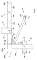
- the Fig. 4 shows a part of a support frame 2 according to the invention in plan view.
- the support frame 2 is part of a support device 300d according to the invention.
- the support frame 2 consists of support frame elements 39a and 39b which are connected to one another by a corner connecting piece 40.
- This corner connector 40 is, analogous to the bracket 12 from the Figures 2a, 2b and 3rd , at the same time holder for an adjusting device 200a, of which only an endless threaded rod 14a and a lock nut 17a are visible in this plan view.
- the laying device 22 and the support bracket 33 are in accordance with the substructure system 100 from FIG Fig. 3 shown.
- Fig. 4 a joint 41 on which a support arm 42 with a support foot 43 is pivotally arranged.
- the support foot 43 is constructed as previously disclosed and comprises an endless threaded rod 14b in a buffer disk 16a and a lock nut 17b.
- a bridge or web 44 is realized on the support frame element 39b by bridging a further support frame element 39d with a support frame element 39c.
- FIG. 5 A support frame 2a according to the invention is shown in a detailed view.
- This support frame 2a has support frame elements 39e and 39f which are connected to a joint 41a. In this way, any number of support frame elements can be combined and adjusted so that the support frame 2a can be used for different basic shapes of shower cells.
- a length adjustment 46 is shown on a support frame side 45, which is arranged between the support frame element 39f and a further support frame element 39g, both of which each have a threaded bushing 49a and 49b, by means of which by turning the longitudinal adjustment 46 on a key holder 47 Threaded body 48b with right-hand thread and another, connected threaded body 48a with left-hand thread press apart or tighten the support frame elements 39f and 39g.
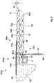
- the Fig. 6 shows an exemplary arrangement of a support device 300e or a substructure system 100a, in which a support plate 27 with a support edge 31a or a flat support surface 3d of the support plate 27 rests on a support surface 3e of the holder 12 - this time mounted upside down.
- the support plate 27 has an assembly or inspection opening 28a, a support plate underside 30 and a support plate top 29 and a blind hole 67a.
- the support plate top 29 is in the horizontal H and is Support for a shower base plate 50a.
- This shower base plate 50a has a shower base plate underside 51a, which is also in the horizontal H.
- the shower base plate 50a furthermore has a shower base plate upper side 52a, which forms a slope surface 32a, in that the latter is at an angle W to the horizontal H.
- the upper edge 21 and the top of the shower base plate 52a adjoin one another at the same height and thus form a shower base 54a which can be laid with base plates or tiles 53a.
- FIG. 7 A further adjustment device 200b according to the invention is schematically shown, which is part of a support device 300f according to the invention.
- the adjusting device 200b is arranged directly on a shower base plate 50b with a mounting or inspection opening 28b, in that a web holder 55 is fastened to a shower base plate underside 51b with screws 56a and 56b.
- the web holder 55 has a bore 57 through which a threaded sleeve 61 is inserted, preferably such that the bore 57 and the threaded sleeve 61 do not touch.
- a spacer ring not shown, made of damping material can also be provided.
- the upper side of the bore 57 forms a support surface 3f for the shower base plate 50b.
- the threaded sleeve 61 is flanged to the web of the web holder 55 with an upper nut 58a and a lower nut 58b. This flanging or screwing of the threaded sleeve 61 to the web holder 55 can take place along any height of a threaded sleeve external thread 64, be it in a pre-assembly or an operation carried out on site.
- the nuts 58a and 58b are each underlaid with a washer 59a and 59b and with a rubber washer 60a and 60b.
- the threaded sleeve 61 also has a threaded sleeve internal thread 65, in which, according to the previously disclosed principle, an endless threaded rod 14c with a longitudinal axis 68a is screwed and is in a buffer disk 16b. Rotations of the endless threaded rod 14c thus cause the support device 300f to be raised or lowered.
- the endless threaded rod 14c can also be screwed in so far that an upper end 66a of the endless threaded rod 14c falls below the level of a shower base plate upper side 52b because a key receptacle 63a at the upper end 66a of the endless threaded rod 14c through a mounting hole 62a in the shower base plate 50b remains operable.
- the mounting hole 62a can be glued with a plug (not shown in more detail) after the height of the support device 300f has been adjusted and any cutting or capping of the endless threaded rod 14c necessary, and then the top of the shower floor panel 52b can be laid with floor panels or tiles.
- the endless threaded rod 14c can preferably be fixed with a lock nut 17c on the lower end face of the threaded sleeve 61 as shown.
- the lock nut 17c can also be more easily accessible through the mounting hole 62a and can be tightened against it with a socket wrench on the upper end face of the threaded sleeve 61.
- the bore 57 together with the nuts 58a and 58b and the threaded sleeve 61 thus forms a receptacle 13a for the endless threaded rod 14c which is fixedly arranged on the web holder 55 and which corresponds to a bore with a thread or a fixed nut of the other design variants of a height adjustment according to the invention, but is also adjustable in a previous and optional assembly step and a higher adjustment range for the height results.
- FIG. 8 Another variant of a multi-part shower base plate 50c according to the invention is shown schematically and in perspective. It consists of a plate part which comprises the drainage system and is thus referred to below as the drainage plate part 69 and a further plate part which basically corresponds to the previously described design variants of support plates or shower base plates and can therefore be referred to below as a support plate part 70 becomes.
- the drainage plate part 69 is preferably factory-assembled with a drainage channel 71 and mounting holes 62b-62e, through which endless threaded rods 14d, 14e and 14f can be operated in height adjustments 200c, 200d and 200e as previously disclosed.
- the drainage plate part 69 has a step-shaped, positively shaped connecting edge 72 with a contact surface 74a, into which rivet nuts 75a-75c are inserted.
- the support plate part 70 has a correspondingly step-shaped, negative connecting edge 73 with a support surface 74b. After the two contact surfaces 74a and 74b have been placed on top of one another, the mounting plate part 70 can be screwed into the rivet nuts 75a-75c by countersunk holes 76a-76c by means of countersunk screws and thus firmly connected to the drainage plate part 69.
- the rivet nuts 75a-75c in the contact surface 74a of the drain plate part 69 are fixed as conventional nuts or as threaded sleeves to a fastening plate 77a on the underside of the drain plate part 69 connected, for example, by welding, provided that the fastening plate 77a is preferably made of weldable metal.
- the fastening plate 77a is preferably made of weldable metal.
Landscapes
- Health & Medical Sciences (AREA)
- Public Health (AREA)
- Epidemiology (AREA)
- General Health & Medical Sciences (AREA)
- Floor Finish (AREA)
- Legs For Furniture In General (AREA)
Claims (16)
- Système de sous-construction (100) pour cellules de douche, avec un dispositif de support (300a) réglable à une hauteur de réglage (VH) avec au moins un réglage en hauteur (200) avec une surface portante (3) pour au moins une plaque (27, 50), dans lequel le réglage en hauteur (200) comprend au moins une tige filetée sans fin (14, 14a-14c), qui est disposée rotativement dans une fixation en forme de L (12) disposée au dispositif de support (300b-300f) ou dans une fixation-traverse en forme de double L (55) disposé dans un récepteur (13, 13a) disposé fixement à la fixation (12, 55), de sorte que lors du montage du système de sous-construction (100, 100a), par rotations de la tige filetée sans fin (14) dans le récepteur (13, 13a), le dispositif de support (300b-300f) est ajustable à une hauteur d'ajustement (JH), où la surface portante (3a-3f) reste en dessous d'une extrémité supérieure (66, 66a) de la tige filetée sans fin (14) et pour laquelle une plaque (27, 50) en forme d'une plaque porteuse (27) ou d'une plaque de base de douche (50) ou d'une plaque porteuse (27) et d'une plaque de base de douche (50) est disposée à la fixation (12, 55) et où la plaque porteuse (27) et/ou la plaque de base de douche (50, 50a, 50b) présente au moins un orifice de montage ou d'inspection (28, 28a, 28b) ou/et au moins un trou de montage (62, 62a) dont le centre est concentrique à un axe longitudinal (68, 68a) de la tige filetée sans fin (14, 14c).
- Système de sous-construction (100) selon la revendication 1, caractérisé en ce que le réglage en hauteur (200) présente un point d'application de force supérieur (11d) au récepteur (13, 13a) et un point d'application de force inférieur (11e) à un disque tampon (16, 16a, 16b).
- Système de sous-construction (100) selon l'une des revendications précédentes, caractérisé en ce que le récepteur (13, 13a) comprend, blocable par des écrous (58a, 58b) à la fixation-traverse (55) une douille filetée (61), qui présente un alésage longitudinal avec un filetage intérieur de douille filetée (65) dans lequel la tige filetée sans fin (14c) est disposée rotative.
- Système de sous-construction (100) selon l'une des revendications précédentes, caractérisé en ce que le dispositif de support (300e) comprend un cadre porteur (2) réglable en hauteur avec au moins un réglage en hauteur (200), la plaque porteuse (27) et la plaque de base de douche (50a).
- Système de sous-construction (100) selon l'une des revendications précédentes 1-3, caractérisé en ce que le dispositif de support (300c) comprend un cadre porteur (2) réglable en hauteur avec au moins un réglage en hauteur (200) et la plaque de base de douche (50).
- Système de sous-construction (100) selon l'une des revendications précédentes 1-3, caractérisé en ce que le dispositif de support (300f) comprend la plaque de base de douche (50b), qui est réglable en hauteur avec au moins un réglage en hauteur (200).
- Système de sous-construction (100) selon l'une des revendications précédentes, caractérisé en ce qu'au dispositif de support (300b-300f) est disposé au moins une console de support (33) réglable et fixable, avec laquelle le dispositif de support (300b-300f) est fixable latéralement dans une niche (19) d'une chape (20).
- Système de sous-construction (100) selon l'une des revendications précédentes, caractérisé en ce qu'au dispositif de support (300b-300f) est disposé au moins un dispositif de mise en place (22), avec lequel le dispositif de support (300b-300f) est plaçable sur un bord supérieur (21) d'une chape (20) et ainsi une hauteur de bord supérieur (OH) du bord supérieur (21) de la chape (20) est adoptable comme dimension de référence pour une hauteur de montage (EH) du dispositif de support (300b-300f).
- Système de sous-construction (100) selon l'une des revendications précédentes, caractérisé en ce que la plaque porteuse (27) et/ou la plaque de base de douche (50, 50a, 50b, 50c) se composent de plusieurs parties de plaques, dont au moins une partie de plaque est au moins partiellement prémontée en usine.
- Système de sous-construction (100) selon la revendication 9, caractérisé en ce que la plaque porteuse (27) et/ou la plaque de base de douche (50, 50a, 50b, 50c) comprend une partie de plaque d'écoulement (69) prémontée en usine et une partie de plaque de mise en place (70) plaçable, et en ce que la partie de plaque d'écoulement (69) et la partie de plaque de mise en place (70) sont connectables à forme finale avec un bord de connexion (72, 73) chacune et une surface portante (74a, 74b) chacune.
- Système de sous-construction (100) selon l'une des revendications précédentes 4, 5 ou 7-10, caractérisé en ce que le cadre porteur (2) est réglable en longueur à au moins un côté de cadre porteur (45) du cadre porteur (2a) avec un réglage en longueur (46).
- Système de sous-construction (100) selon l'une des revendications précédentes 4, 5 ou 7-11, caractérisé en ce que le cadre porteur (2) est intégré dans la plaque porteuse (27) ou la plaque de base de douche (50).
- Système de sous-construction (100) selon l'une des revendications précédentes 4, 5 ou 7-12, caractérisé en ce qu'au moins un joint (41) est disposé entre deux éléments de cadre porteur (39a, 39b) du cadre porteur (2), de sorte que le cadre porteur (2) est adaptable à différentes formes géométriques de base.
- Système de sous-construction (100) selon l'une des revendications précédentes 4, 5 ou 7-13, caractérisé en ce que le cadre porteur (2) comprend au moins un bras de support pivotant (42) avec un pied de support (43) réglable en hauteur en continu.
- Système de sous-construction (100) selon l'une des revendications précédentes 1-4 ou 7-14, caractérisé en ce qu'un dessus de plaque porteuse (29) ou un dessus de plaque de base de douche (52) forme au moins une surface inclinée (32), qui est disposée à un angle (W) par rapport à l'horizontale (H).
- Procédure de montage d'un système de sous-structure de cellule de douche (100) selon l'une des revendications précédentes 8-14, caractérisée en ce que les pas suivants sont exécutés:- appuyer d'un dispositif de support (300b-300f) au moyen d'au moins une plaque d'appui (23) d'au moins un dispositif de mise en place (22) sur un bord supérieur (21) d'une niche (19) d'une chape (20);- ajustage d'une hauteur de montage (EH) en tournant au moins une tige filetée sans fin (14);- réglage et fixation d'au moins une console de support (33);- appuyer d'au moins une plaque (26), où les pas mentionnés aux tirets le troisième et quatrième sont également réversibles.
Applications Claiming Priority (1)
| Application Number | Priority Date | Filing Date | Title |
|---|---|---|---|
| AT2652009 | 2009-04-24 |
Publications (4)
| Publication Number | Publication Date |
|---|---|
| EP2245973A2 EP2245973A2 (fr) | 2010-11-03 |
| EP2245973A3 EP2245973A3 (fr) | 2014-10-22 |
| EP2245973B1 true EP2245973B1 (fr) | 2020-04-08 |
| EP2245973B8 EP2245973B8 (fr) | 2020-08-26 |
Family
ID=42355339
Family Applications (1)
| Application Number | Title | Priority Date | Filing Date |
|---|---|---|---|
| EP10004271.2A Active EP2245973B8 (fr) | 2009-04-24 | 2010-04-22 | Système de sous-construction pour bacs de douche et sols de douche |
Country Status (1)
| Country | Link |
|---|---|
| EP (1) | EP2245973B8 (fr) |
Families Citing this family (8)
| Publication number | Priority date | Publication date | Assignee | Title |
|---|---|---|---|---|
| CH704937B1 (de) * | 2011-09-21 | 2012-11-15 | Urs Gassmann | Tragboard zum Setzen einer Bade- oder Duschwanne. |
| EP2687136B1 (fr) * | 2012-07-20 | 2017-03-15 | Dallmer GmbH & Co. KG | Élément de douche |
| CH706848B1 (de) * | 2012-08-17 | 2016-09-30 | Gassmann Urs | Duschbodenplatte und Verfahren zum Montieren dieser Duschbodenplatte. |
| EP2700342B1 (fr) | 2012-08-19 | 2018-04-25 | Urs Gassmann | Plaque pour sol de douche |
| EP3056618B1 (fr) * | 2015-02-10 | 2018-05-30 | SANIPAT GmbH | Socle de gouttiere reglable en hauteur pour recouvrir une gouttiere |
| CN107916605A (zh) * | 2017-10-16 | 2018-04-17 | 广东省建筑科学研究院集团股份有限公司 | 一种用于改性树脂多功能路面超薄层施工的摊铺车 |
| CN111481087A (zh) * | 2019-01-25 | 2020-08-04 | 华中科技大学同济医学院附属协和医院 | 一种移动洗浴装置 |
| CN119184525B (zh) * | 2024-11-05 | 2026-04-28 | 华科住宅工业(东莞)有限公司 | 一种整体卫浴防漏水的拼装底盘 |
Family Cites Families (5)
| Publication number | Priority date | Publication date | Assignee | Title |
|---|---|---|---|---|
| DE9317159U1 (de) * | 1993-11-10 | 1994-02-10 | Beckmann, Hans-Jürgen, 23623 Ahrensbök | Universalgestell für Viertelkreis- und 5-Eck-Brausewannen |
| DE29602386U1 (de) * | 1996-02-12 | 1996-04-25 | Alpha - Sanitärvertriebs GmbH, 47805 Krefeld | Wannenträger, insbesondere Badewannen- und Duschwannenträger |
| HUP0202454A2 (en) * | 1999-03-23 | 2002-12-28 | Illbruck Sanitaertechnik Gmbh | Method for installing a tub support and tub shell mounted in a tub support |
| JP2002088839A (ja) * | 2000-09-21 | 2002-03-27 | Toto Ltd | 排水トラップを備えた浴室ユニット |
| AT8143U1 (de) * | 2004-12-10 | 2006-02-15 | Hl Hutterer & Lechner Gmbh | Befestigungselement für einen sanitärbauteil |
-
2010
- 2010-04-22 EP EP10004271.2A patent/EP2245973B8/fr active Active
Non-Patent Citations (1)
| Title |
|---|
| None * |
Also Published As
| Publication number | Publication date |
|---|---|
| EP2245973B8 (fr) | 2020-08-26 |
| EP2245973A2 (fr) | 2010-11-03 |
| EP2245973A3 (fr) | 2014-10-22 |
Similar Documents
| Publication | Publication Date | Title |
|---|---|---|
| EP3031990B1 (fr) | Siphon de sol | |
| EP2245973A2 (fr) | Système de sous-construction pour bacs de douche et sols de douche | |
| DE102006007471B4 (de) | Duschbodenelement und Trägerelement dafür, sowie Duschbodenunterbau aus einem Duschbodenelement und einem Trägerelement für bodengleiche Duschen | |
| EP2756137B1 (fr) | Caniveau d'évacuation pour une douche ras du sol | |
| DE102011051739B4 (de) | Montageeinheit für eine Unterputz-Sanitärarmatur | |
| EP2067902B1 (fr) | Procédé d'intégration d'une évacuation dans un sous-sol, évacuation dotée d'un bac d'évacuation ainsi que sols de bâtiments dotés d'une telle évacuation | |
| DE202008005293U1 (de) | Duschbodenuntergestell | |
| AT508227B1 (de) | Unterbausystem für duschwannen und duschböden | |
| DE102004049130A1 (de) | Duschwanne mit auf einem höhenverstellbaren Duschwannenträger aufsetzbarer Duschwannenschale | |
| DE202005004179U1 (de) | Duschbodenaufbau | |
| DE202006019814U1 (de) | Duschbodenelement für bodengleiche Duschen | |
| DE4124460A1 (de) | Installationsblock | |
| EP2929818B1 (fr) | Bac à douche | |
| DE29507126U1 (de) | Nachträglich anbaubarer Balkon oder Wintergarten | |
| EP2177689B1 (fr) | Cadre doté d'un couvercle | |
| WO2010075855A1 (fr) | Système de goujon pour construction en béton | |
| EP3339522B1 (fr) | Système ou kit de fixation de caniveaux de douche | |
| KR200182865Y1 (ko) | 거푸집 레벨 조정장치 | |
| DE202006019811U1 (de) | Trägerelement für ein Duschbodenelement für bodengleiche Duschen | |
| EP2700342B1 (fr) | Plaque pour sol de douche | |
| DE19648101C1 (de) | Installationsbodenstütze | |
| CH708080B1 (de) | Justierbare Duschrinnenabdeckung. | |
| DE202004015439U1 (de) | Raumzelle zum Einbau in einen Raum eines Bauwerks | |
| DE202006004863U1 (de) | Duschbodenelement | |
| WO1997044550A1 (fr) | Revetement de sol |
Legal Events
| Date | Code | Title | Description |
|---|---|---|---|
| PUAI | Public reference made under article 153(3) epc to a published international application that has entered the european phase |
Free format text: ORIGINAL CODE: 0009012 |
|
| AK | Designated contracting states |
Kind code of ref document: A2 Designated state(s): AT BE BG CH CY CZ DE DK EE ES FI FR GB GR HR HU IE IS IT LI LT LU LV MC MK MT NL NO PL PT RO SE SI SK SM TR |
|
| AX | Request for extension of the european patent |
Extension state: AL BA ME RS |
|
| PUAL | Search report despatched |
Free format text: ORIGINAL CODE: 0009013 |
|
| AK | Designated contracting states |
Kind code of ref document: A3 Designated state(s): AT BE BG CH CY CZ DE DK EE ES FI FR GB GR HR HU IE IS IT LI LT LU LV MC MK MT NL NO PL PT RO SE SI SK SM TR |
|
| AX | Request for extension of the european patent |
Extension state: AL BA ME RS |
|
| RIC1 | Information provided on ipc code assigned before grant |
Ipc: A47K 3/16 20060101AFI20140917BHEP Ipc: A47K 3/17 20060101ALI20140917BHEP Ipc: A47K 3/40 20060101ALI20140917BHEP |
|
| 17P | Request for examination filed |
Effective date: 20150420 |
|
| RBV | Designated contracting states (corrected) |
Designated state(s): AT BE BG CH CY CZ DE DK EE ES FI FR GB GR HR HU IE IS IT LI LT LU LV MC MK MT NL NO PL PT RO SE SI SK SM TR |
|
| STAA | Information on the status of an ep patent application or granted ep patent |
Free format text: STATUS: EXAMINATION IS IN PROGRESS |
|
| 17Q | First examination report despatched |
Effective date: 20180925 |
|
| RAP1 | Party data changed (applicant data changed or rights of an application transferred) |
Owner name: SANIPAT GMBH |
|
| RIN1 | Information on inventor provided before grant (corrected) |
Inventor name: SANIPAT GMBH |
|
| GRAP | Despatch of communication of intention to grant a patent |
Free format text: ORIGINAL CODE: EPIDOSNIGR1 |
|
| STAA | Information on the status of an ep patent application or granted ep patent |
Free format text: STATUS: GRANT OF PATENT IS INTENDED |
|
| INTG | Intention to grant announced |
Effective date: 20191022 |
|
| GRAS | Grant fee paid |
Free format text: ORIGINAL CODE: EPIDOSNIGR3 |
|
| GRAA | (expected) grant |
Free format text: ORIGINAL CODE: 0009210 |
|
| STAA | Information on the status of an ep patent application or granted ep patent |
Free format text: STATUS: THE PATENT HAS BEEN GRANTED |
|
| AK | Designated contracting states |
Kind code of ref document: B1 Designated state(s): AT BE BG CH CY CZ DE DK EE ES FI FR GB GR HR HU IE IS IT LI LT LU LV MC MK MT NL NO PL PT RO SE SI SK SM TR |
|
| REG | Reference to a national code |
Ref country code: GB Ref legal event code: FG4D Free format text: NOT ENGLISH |
|
| RIN1 | Information on inventor provided before grant (corrected) |
Inventor name: GRASSMANN, URS |
|
| REG | Reference to a national code |
Ref country code: CH Ref legal event code: EP Ref country code: AT Ref legal event code: REF Ref document number: 1253203 Country of ref document: AT Kind code of ref document: T Effective date: 20200415 |
|
| REG | Reference to a national code |
Ref country code: DE Ref legal event code: R096 Ref document number: 502010016563 Country of ref document: DE |
|
| REG | Reference to a national code |
Ref country code: IE Ref legal event code: FG4D Free format text: LANGUAGE OF EP DOCUMENT: GERMAN |
|
| GRAT | Correction requested after decision to grant or after decision to maintain patent in amended form |
Free format text: ORIGINAL CODE: EPIDOSNCDEC |
|
| REG | Reference to a national code |
Ref country code: CH Ref legal event code: NV Representative=s name: PATENT- AND MARKENBUERO REB GMBH, CH Ref country code: CH Ref legal event code: PK Free format text: BERICHTIGUNG ERFINDER |
|
| REG | Reference to a national code |
Ref country code: CH Ref legal event code: PK Free format text: BERICHTIGUNG B8 Ref country code: CH Ref legal event code: PK Free format text: BERICHTIGUNGEN |
|
| RIN2 | Information on inventor provided after grant (corrected) |
Inventor name: GASSMANN, URS |
|
| REG | Reference to a national code |
Ref country code: NL Ref legal event code: MP Effective date: 20200408 |
|
| REG | Reference to a national code |
Ref country code: LT Ref legal event code: MG4D |
|
| PG25 | Lapsed in a contracting state [announced via postgrant information from national office to epo] |
Ref country code: FI Free format text: LAPSE BECAUSE OF FAILURE TO SUBMIT A TRANSLATION OF THE DESCRIPTION OR TO PAY THE FEE WITHIN THE PRESCRIBED TIME-LIMIT Effective date: 20200408 Ref country code: GR Free format text: LAPSE BECAUSE OF FAILURE TO SUBMIT A TRANSLATION OF THE DESCRIPTION OR TO PAY THE FEE WITHIN THE PRESCRIBED TIME-LIMIT Effective date: 20200709 Ref country code: LT Free format text: LAPSE BECAUSE OF FAILURE TO SUBMIT A TRANSLATION OF THE DESCRIPTION OR TO PAY THE FEE WITHIN THE PRESCRIBED TIME-LIMIT Effective date: 20200408 Ref country code: PT Free format text: LAPSE BECAUSE OF FAILURE TO SUBMIT A TRANSLATION OF THE DESCRIPTION OR TO PAY THE FEE WITHIN THE PRESCRIBED TIME-LIMIT Effective date: 20200817 Ref country code: IS Free format text: LAPSE BECAUSE OF FAILURE TO SUBMIT A TRANSLATION OF THE DESCRIPTION OR TO PAY THE FEE WITHIN THE PRESCRIBED TIME-LIMIT Effective date: 20200808 Ref country code: NO Free format text: LAPSE BECAUSE OF FAILURE TO SUBMIT A TRANSLATION OF THE DESCRIPTION OR TO PAY THE FEE WITHIN THE PRESCRIBED TIME-LIMIT Effective date: 20200708 Ref country code: SE Free format text: LAPSE BECAUSE OF FAILURE TO SUBMIT A TRANSLATION OF THE DESCRIPTION OR TO PAY THE FEE WITHIN THE PRESCRIBED TIME-LIMIT Effective date: 20200408 Ref country code: NL Free format text: LAPSE BECAUSE OF FAILURE TO SUBMIT A TRANSLATION OF THE DESCRIPTION OR TO PAY THE FEE WITHIN THE PRESCRIBED TIME-LIMIT Effective date: 20200408 |
|
| PG25 | Lapsed in a contracting state [announced via postgrant information from national office to epo] |
Ref country code: HR Free format text: LAPSE BECAUSE OF FAILURE TO SUBMIT A TRANSLATION OF THE DESCRIPTION OR TO PAY THE FEE WITHIN THE PRESCRIBED TIME-LIMIT Effective date: 20200408 Ref country code: BG Free format text: LAPSE BECAUSE OF FAILURE TO SUBMIT A TRANSLATION OF THE DESCRIPTION OR TO PAY THE FEE WITHIN THE PRESCRIBED TIME-LIMIT Effective date: 20200708 Ref country code: LV Free format text: LAPSE BECAUSE OF FAILURE TO SUBMIT A TRANSLATION OF THE DESCRIPTION OR TO PAY THE FEE WITHIN THE PRESCRIBED TIME-LIMIT Effective date: 20200408 |
|
| REG | Reference to a national code |
Ref country code: DE Ref legal event code: R097 Ref document number: 502010016563 Country of ref document: DE |
|
| PG25 | Lapsed in a contracting state [announced via postgrant information from national office to epo] |
Ref country code: ES Free format text: LAPSE BECAUSE OF FAILURE TO SUBMIT A TRANSLATION OF THE DESCRIPTION OR TO PAY THE FEE WITHIN THE PRESCRIBED TIME-LIMIT Effective date: 20200408 Ref country code: MC Free format text: LAPSE BECAUSE OF FAILURE TO SUBMIT A TRANSLATION OF THE DESCRIPTION OR TO PAY THE FEE WITHIN THE PRESCRIBED TIME-LIMIT Effective date: 20200408 Ref country code: DK Free format text: LAPSE BECAUSE OF FAILURE TO SUBMIT A TRANSLATION OF THE DESCRIPTION OR TO PAY THE FEE WITHIN THE PRESCRIBED TIME-LIMIT Effective date: 20200408 Ref country code: EE Free format text: LAPSE BECAUSE OF FAILURE TO SUBMIT A TRANSLATION OF THE DESCRIPTION OR TO PAY THE FEE WITHIN THE PRESCRIBED TIME-LIMIT Effective date: 20200408 Ref country code: SM Free format text: LAPSE BECAUSE OF FAILURE TO SUBMIT A TRANSLATION OF THE DESCRIPTION OR TO PAY THE FEE WITHIN THE PRESCRIBED TIME-LIMIT Effective date: 20200408 Ref country code: IT Free format text: LAPSE BECAUSE OF FAILURE TO SUBMIT A TRANSLATION OF THE DESCRIPTION OR TO PAY THE FEE WITHIN THE PRESCRIBED TIME-LIMIT Effective date: 20200408 Ref country code: RO Free format text: LAPSE BECAUSE OF FAILURE TO SUBMIT A TRANSLATION OF THE DESCRIPTION OR TO PAY THE FEE WITHIN THE PRESCRIBED TIME-LIMIT Effective date: 20200408 Ref country code: CZ Free format text: LAPSE BECAUSE OF FAILURE TO SUBMIT A TRANSLATION OF THE DESCRIPTION OR TO PAY THE FEE WITHIN THE PRESCRIBED TIME-LIMIT Effective date: 20200408 Ref country code: LU Free format text: LAPSE BECAUSE OF NON-PAYMENT OF DUE FEES Effective date: 20200422 |
|
| REG | Reference to a national code |
Ref country code: BE Ref legal event code: MM Effective date: 20200430 |
|
| PLBE | No opposition filed within time limit |
Free format text: ORIGINAL CODE: 0009261 |
|
| STAA | Information on the status of an ep patent application or granted ep patent |
Free format text: STATUS: NO OPPOSITION FILED WITHIN TIME LIMIT |
|
| PG25 | Lapsed in a contracting state [announced via postgrant information from national office to epo] |
Ref country code: PL Free format text: LAPSE BECAUSE OF FAILURE TO SUBMIT A TRANSLATION OF THE DESCRIPTION OR TO PAY THE FEE WITHIN THE PRESCRIBED TIME-LIMIT Effective date: 20200408 Ref country code: SK Free format text: LAPSE BECAUSE OF FAILURE TO SUBMIT A TRANSLATION OF THE DESCRIPTION OR TO PAY THE FEE WITHIN THE PRESCRIBED TIME-LIMIT Effective date: 20200408 Ref country code: BE Free format text: LAPSE BECAUSE OF NON-PAYMENT OF DUE FEES Effective date: 20200430 |
|
| 26N | No opposition filed |
Effective date: 20210112 |
|
| GBPC | Gb: european patent ceased through non-payment of renewal fee |
Effective date: 20200708 |
|
| PG25 | Lapsed in a contracting state [announced via postgrant information from national office to epo] |
Ref country code: IE Free format text: LAPSE BECAUSE OF NON-PAYMENT OF DUE FEES Effective date: 20200422 Ref country code: FR Free format text: LAPSE BECAUSE OF NON-PAYMENT OF DUE FEES Effective date: 20200608 Ref country code: GB Free format text: LAPSE BECAUSE OF NON-PAYMENT OF DUE FEES Effective date: 20200708 |
|
| PG25 | Lapsed in a contracting state [announced via postgrant information from national office to epo] |
Ref country code: SI Free format text: LAPSE BECAUSE OF FAILURE TO SUBMIT A TRANSLATION OF THE DESCRIPTION OR TO PAY THE FEE WITHIN THE PRESCRIBED TIME-LIMIT Effective date: 20200408 |
|
| PG25 | Lapsed in a contracting state [announced via postgrant information from national office to epo] |
Ref country code: TR Free format text: LAPSE BECAUSE OF FAILURE TO SUBMIT A TRANSLATION OF THE DESCRIPTION OR TO PAY THE FEE WITHIN THE PRESCRIBED TIME-LIMIT Effective date: 20200408 Ref country code: MT Free format text: LAPSE BECAUSE OF FAILURE TO SUBMIT A TRANSLATION OF THE DESCRIPTION OR TO PAY THE FEE WITHIN THE PRESCRIBED TIME-LIMIT Effective date: 20200408 Ref country code: CY Free format text: LAPSE BECAUSE OF FAILURE TO SUBMIT A TRANSLATION OF THE DESCRIPTION OR TO PAY THE FEE WITHIN THE PRESCRIBED TIME-LIMIT Effective date: 20200408 |
|
| PG25 | Lapsed in a contracting state [announced via postgrant information from national office to epo] |
Ref country code: MK Free format text: LAPSE BECAUSE OF FAILURE TO SUBMIT A TRANSLATION OF THE DESCRIPTION OR TO PAY THE FEE WITHIN THE PRESCRIBED TIME-LIMIT Effective date: 20200408 |
|
| PGFP | Annual fee paid to national office [announced via postgrant information from national office to epo] |
Ref country code: DE Payment date: 20230418 Year of fee payment: 14 Ref country code: CH Payment date: 20230502 Year of fee payment: 14 |
|
| PGFP | Annual fee paid to national office [announced via postgrant information from national office to epo] |
Ref country code: AT Payment date: 20230414 Year of fee payment: 14 |
|
| REG | Reference to a national code |
Ref country code: DE Ref legal event code: R119 Ref document number: 502010016563 Country of ref document: DE |
|
| REG | Reference to a national code |
Ref country code: CH Ref legal event code: PL |
|
| REG | Reference to a national code |
Ref country code: AT Ref legal event code: MM01 Ref document number: 1253203 Country of ref document: AT Kind code of ref document: T Effective date: 20240422 |
|
| PG25 | Lapsed in a contracting state [announced via postgrant information from national office to epo] |
Ref country code: DE Free format text: LAPSE BECAUSE OF NON-PAYMENT OF DUE FEES Effective date: 20241105 |
|
| PG25 | Lapsed in a contracting state [announced via postgrant information from national office to epo] |
Ref country code: AT Free format text: LAPSE BECAUSE OF NON-PAYMENT OF DUE FEES Effective date: 20240422 |
|
| PG25 | Lapsed in a contracting state [announced via postgrant information from national office to epo] |
Ref country code: DE Free format text: LAPSE BECAUSE OF NON-PAYMENT OF DUE FEES Effective date: 20241105 Ref country code: AT Free format text: LAPSE BECAUSE OF NON-PAYMENT OF DUE FEES Effective date: 20240422 Ref country code: CH Free format text: LAPSE BECAUSE OF NON-PAYMENT OF DUE FEES Effective date: 20240430 |