EP2245255B1 - Verfahren und vorrichtung zur herstellung eines bohrlochmotorradiallagers - Google Patents
Verfahren und vorrichtung zur herstellung eines bohrlochmotorradiallagers Download PDFInfo
- Publication number
- EP2245255B1 EP2245255B1 EP08763070.3A EP08763070A EP2245255B1 EP 2245255 B1 EP2245255 B1 EP 2245255B1 EP 08763070 A EP08763070 A EP 08763070A EP 2245255 B1 EP2245255 B1 EP 2245255B1
- Authority
- EP
- European Patent Office
- Prior art keywords
- radial bearing
- abrasion
- bearing body
- layer
- interior surface
- Prior art date
- Legal status (The legal status is an assumption and is not a legal conclusion. Google has not performed a legal analysis and makes no representation as to the accuracy of the status listed.)
- Not-in-force
Links
- 238000000034 method Methods 0.000 title claims description 30
- 238000004519 manufacturing process Methods 0.000 title claims description 8
- 238000005299 abrasion Methods 0.000 claims description 81
- 239000000463 material Substances 0.000 claims description 57
- 229910052751 metal Inorganic materials 0.000 claims description 28
- 239000002184 metal Substances 0.000 claims description 28
- 239000011159 matrix material Substances 0.000 claims description 15
- 238000003754 machining Methods 0.000 claims description 13
- 229910000831 Steel Inorganic materials 0.000 claims description 11
- 239000010959 steel Substances 0.000 claims description 11
- 229910000851 Alloy steel Inorganic materials 0.000 claims description 7
- 229910000990 Ni alloy Inorganic materials 0.000 claims description 6
- 239000000843 powder Substances 0.000 claims description 6
- 239000000203 mixture Substances 0.000 claims description 5
- UONOETXJSWQNOL-UHFFFAOYSA-N tungsten carbide Chemical compound [W+]#[C-] UONOETXJSWQNOL-UHFFFAOYSA-N 0.000 claims description 5
- MTPVUVINMAGMJL-UHFFFAOYSA-N trimethyl(1,1,2,2,2-pentafluoroethyl)silane Chemical compound C[Si](C)(C)C(F)(F)C(F)(F)F MTPVUVINMAGMJL-UHFFFAOYSA-N 0.000 claims description 4
- 238000001816 cooling Methods 0.000 claims description 3
- 208000035874 Excoriation Diseases 0.000 description 59
- 238000005553 drilling Methods 0.000 description 12
- PXHVJJICTQNCMI-UHFFFAOYSA-N Nickel Chemical compound [Ni] PXHVJJICTQNCMI-UHFFFAOYSA-N 0.000 description 4
- 238000005520 cutting process Methods 0.000 description 4
- 229910045601 alloy Inorganic materials 0.000 description 3
- 239000000956 alloy Substances 0.000 description 3
- 238000000576 coating method Methods 0.000 description 3
- 238000010438 heat treatment Methods 0.000 description 3
- 230000002093 peripheral effect Effects 0.000 description 3
- UDHXJZHVNHGCEC-UHFFFAOYSA-N Chlorophacinone Chemical compound C1=CC(Cl)=CC=C1C(C=1C=CC=CC=1)C(=O)C1C(=O)C2=CC=CC=C2C1=O UDHXJZHVNHGCEC-UHFFFAOYSA-N 0.000 description 2
- 239000011248 coating agent Substances 0.000 description 2
- 238000005552 hardfacing Methods 0.000 description 2
- 229910052759 nickel Inorganic materials 0.000 description 2
- 230000035515 penetration Effects 0.000 description 2
- 238000010791 quenching Methods 0.000 description 2
- 230000000171 quenching effect Effects 0.000 description 2
- 230000035939 shock Effects 0.000 description 2
- 238000003466 welding Methods 0.000 description 2
- 229910001104 4140 steel Inorganic materials 0.000 description 1
- 229910000975 Carbon steel Inorganic materials 0.000 description 1
- VYZAMTAEIAYCRO-UHFFFAOYSA-N Chromium Chemical compound [Cr] VYZAMTAEIAYCRO-UHFFFAOYSA-N 0.000 description 1
- RYGMFSIKBFXOCR-UHFFFAOYSA-N Copper Chemical compound [Cu] RYGMFSIKBFXOCR-UHFFFAOYSA-N 0.000 description 1
- 229910000881 Cu alloy Inorganic materials 0.000 description 1
- 229910000914 Mn alloy Inorganic materials 0.000 description 1
- ZOKXTWBITQBERF-UHFFFAOYSA-N Molybdenum Chemical compound [Mo] ZOKXTWBITQBERF-UHFFFAOYSA-N 0.000 description 1
- 230000009286 beneficial effect Effects 0.000 description 1
- 239000010962 carbon steel Substances 0.000 description 1
- 229910052804 chromium Inorganic materials 0.000 description 1
- 239000011651 chromium Substances 0.000 description 1
- 238000010276 construction Methods 0.000 description 1
- 239000010949 copper Substances 0.000 description 1
- 230000002950 deficient Effects 0.000 description 1
- 238000000151 deposition Methods 0.000 description 1
- 230000000694 effects Effects 0.000 description 1
- 238000000605 extraction Methods 0.000 description 1
- 239000000835 fiber Substances 0.000 description 1
- 238000000227 grinding Methods 0.000 description 1
- 230000008595 infiltration Effects 0.000 description 1
- 238000001764 infiltration Methods 0.000 description 1
- 238000012423 maintenance Methods 0.000 description 1
- 229910052750 molybdenum Inorganic materials 0.000 description 1
- 239000011733 molybdenum Substances 0.000 description 1
- 230000003287 optical effect Effects 0.000 description 1
- 239000002245 particle Substances 0.000 description 1
- 230000000149 penetrating effect Effects 0.000 description 1
- 238000000926 separation method Methods 0.000 description 1
- 239000007921 spray Substances 0.000 description 1
- 238000005507 spraying Methods 0.000 description 1
- 238000011144 upstream manufacturing Methods 0.000 description 1
Images


Classifications
-
- F—MECHANICAL ENGINEERING; LIGHTING; HEATING; WEAPONS; BLASTING
- F16—ENGINEERING ELEMENTS AND UNITS; GENERAL MEASURES FOR PRODUCING AND MAINTAINING EFFECTIVE FUNCTIONING OF MACHINES OR INSTALLATIONS; THERMAL INSULATION IN GENERAL
- F16C—SHAFTS; FLEXIBLE SHAFTS; ELEMENTS OR CRANKSHAFT MECHANISMS; ROTARY BODIES OTHER THAN GEARING ELEMENTS; BEARINGS
- F16C33/00—Parts of bearings; Special methods for making bearings or parts thereof
- F16C33/02—Parts of sliding-contact bearings
- F16C33/04—Brasses; Bushes; Linings
- F16C33/06—Sliding surface mainly made of metal
-
- E—FIXED CONSTRUCTIONS
- E21—EARTH OR ROCK DRILLING; MINING
- E21B—EARTH OR ROCK DRILLING; OBTAINING OIL, GAS, WATER, SOLUBLE OR MELTABLE MATERIALS OR A SLURRY OF MINERALS FROM WELLS
- E21B4/00—Drives for drilling, used in the borehole
- E21B4/003—Bearing, sealing, lubricating details
-
- E—FIXED CONSTRUCTIONS
- E21—EARTH OR ROCK DRILLING; MINING
- E21B—EARTH OR ROCK DRILLING; OBTAINING OIL, GAS, WATER, SOLUBLE OR MELTABLE MATERIALS OR A SLURRY OF MINERALS FROM WELLS
- E21B23/00—Apparatus for displacing, setting, locking, releasing or removing tools, packers or the like in boreholes or wells
- E21B23/04—Apparatus for displacing, setting, locking, releasing or removing tools, packers or the like in boreholes or wells operated by fluid means, e.g. actuated by explosion
- E21B23/0419—Apparatus for displacing, setting, locking, releasing or removing tools, packers or the like in boreholes or wells operated by fluid means, e.g. actuated by explosion using down-hole motor and pump arrangements for generating hydraulic pressure
-
- F—MECHANICAL ENGINEERING; LIGHTING; HEATING; WEAPONS; BLASTING
- F16—ENGINEERING ELEMENTS AND UNITS; GENERAL MEASURES FOR PRODUCING AND MAINTAINING EFFECTIVE FUNCTIONING OF MACHINES OR INSTALLATIONS; THERMAL INSULATION IN GENERAL
- F16C—SHAFTS; FLEXIBLE SHAFTS; ELEMENTS OR CRANKSHAFT MECHANISMS; ROTARY BODIES OTHER THAN GEARING ELEMENTS; BEARINGS
- F16C17/00—Sliding-contact bearings for exclusively rotary movement
- F16C17/02—Sliding-contact bearings for exclusively rotary movement for radial load only
-
- F—MECHANICAL ENGINEERING; LIGHTING; HEATING; WEAPONS; BLASTING
- F16—ENGINEERING ELEMENTS AND UNITS; GENERAL MEASURES FOR PRODUCING AND MAINTAINING EFFECTIVE FUNCTIONING OF MACHINES OR INSTALLATIONS; THERMAL INSULATION IN GENERAL
- F16C—SHAFTS; FLEXIBLE SHAFTS; ELEMENTS OR CRANKSHAFT MECHANISMS; ROTARY BODIES OTHER THAN GEARING ELEMENTS; BEARINGS
- F16C19/00—Bearings with rolling contact, for exclusively rotary movement
- F16C19/02—Bearings with rolling contact, for exclusively rotary movement with bearing balls essentially of the same size in one or more circular rows
- F16C19/14—Bearings with rolling contact, for exclusively rotary movement with bearing balls essentially of the same size in one or more circular rows for both radial and axial load
- F16C19/18—Bearings with rolling contact, for exclusively rotary movement with bearing balls essentially of the same size in one or more circular rows for both radial and axial load with two or more rows of balls
-
- F—MECHANICAL ENGINEERING; LIGHTING; HEATING; WEAPONS; BLASTING
- F16—ENGINEERING ELEMENTS AND UNITS; GENERAL MEASURES FOR PRODUCING AND MAINTAINING EFFECTIVE FUNCTIONING OF MACHINES OR INSTALLATIONS; THERMAL INSULATION IN GENERAL
- F16C—SHAFTS; FLEXIBLE SHAFTS; ELEMENTS OR CRANKSHAFT MECHANISMS; ROTARY BODIES OTHER THAN GEARING ELEMENTS; BEARINGS
- F16C21/00—Combinations of sliding-contact bearings with ball or roller bearings, for exclusively rotary movement
-
- F—MECHANICAL ENGINEERING; LIGHTING; HEATING; WEAPONS; BLASTING
- F16—ENGINEERING ELEMENTS AND UNITS; GENERAL MEASURES FOR PRODUCING AND MAINTAINING EFFECTIVE FUNCTIONING OF MACHINES OR INSTALLATIONS; THERMAL INSULATION IN GENERAL
- F16C—SHAFTS; FLEXIBLE SHAFTS; ELEMENTS OR CRANKSHAFT MECHANISMS; ROTARY BODIES OTHER THAN GEARING ELEMENTS; BEARINGS
- F16C33/00—Parts of bearings; Special methods for making bearings or parts thereof
- F16C33/02—Parts of sliding-contact bearings
- F16C33/04—Brasses; Bushes; Linings
- F16C33/043—Sliding surface consisting mainly of ceramics, cermets or hard carbon, e.g. diamond like carbon [DLC]
-
- F—MECHANICAL ENGINEERING; LIGHTING; HEATING; WEAPONS; BLASTING
- F16—ENGINEERING ELEMENTS AND UNITS; GENERAL MEASURES FOR PRODUCING AND MAINTAINING EFFECTIVE FUNCTIONING OF MACHINES OR INSTALLATIONS; THERMAL INSULATION IN GENERAL
- F16C—SHAFTS; FLEXIBLE SHAFTS; ELEMENTS OR CRANKSHAFT MECHANISMS; ROTARY BODIES OTHER THAN GEARING ELEMENTS; BEARINGS
- F16C33/00—Parts of bearings; Special methods for making bearings or parts thereof
- F16C33/02—Parts of sliding-contact bearings
- F16C33/04—Brasses; Bushes; Linings
- F16C33/06—Sliding surface mainly made of metal
- F16C33/14—Special methods of manufacture; Running-in
-
- F—MECHANICAL ENGINEERING; LIGHTING; HEATING; WEAPONS; BLASTING
- F16—ENGINEERING ELEMENTS AND UNITS; GENERAL MEASURES FOR PRODUCING AND MAINTAINING EFFECTIVE FUNCTIONING OF MACHINES OR INSTALLATIONS; THERMAL INSULATION IN GENERAL
- F16C—SHAFTS; FLEXIBLE SHAFTS; ELEMENTS OR CRANKSHAFT MECHANISMS; ROTARY BODIES OTHER THAN GEARING ELEMENTS; BEARINGS
- F16C2223/00—Surface treatments; Hardening; Coating
- F16C2223/30—Coating surfaces
- F16C2223/46—Coating surfaces by welding, e.g. by using a laser to build a layer
-
- F—MECHANICAL ENGINEERING; LIGHTING; HEATING; WEAPONS; BLASTING
- F16—ENGINEERING ELEMENTS AND UNITS; GENERAL MEASURES FOR PRODUCING AND MAINTAINING EFFECTIVE FUNCTIONING OF MACHINES OR INSTALLATIONS; THERMAL INSULATION IN GENERAL
- F16C—SHAFTS; FLEXIBLE SHAFTS; ELEMENTS OR CRANKSHAFT MECHANISMS; ROTARY BODIES OTHER THAN GEARING ELEMENTS; BEARINGS
- F16C2352/00—Apparatus for drilling
-
- Y—GENERAL TAGGING OF NEW TECHNOLOGICAL DEVELOPMENTS; GENERAL TAGGING OF CROSS-SECTIONAL TECHNOLOGIES SPANNING OVER SEVERAL SECTIONS OF THE IPC; TECHNICAL SUBJECTS COVERED BY FORMER USPC CROSS-REFERENCE ART COLLECTIONS [XRACs] AND DIGESTS
- Y10—TECHNICAL SUBJECTS COVERED BY FORMER USPC
- Y10T—TECHNICAL SUBJECTS COVERED BY FORMER US CLASSIFICATION
- Y10T29/00—Metal working
- Y10T29/49—Method of mechanical manufacture
- Y10T29/49636—Process for making bearing or component thereof
- Y10T29/49643—Rotary bearing
Definitions
- the present invention concerns the down hole motors used in the oil prospecting industry to drive drill bits for drilling the ground at great depths.
- a down hole motor is used for this, fixed to the lower end of a drillstring, and driving a drill bit in axial rotation.
- the down hole motor comprises a shaft engaged for axial rotation in a motor body and carrying the drill bit at its end.
- the shaft is held in the motor body by sliding bearings, in particular a radial bearing.
- the motors are driven by the drilling mud injected to bring up the cuttings. It is this mixture of cuttings and drilling mud that subjects this equipment to particularly severe abrasion.
- Bearings have already been manufactured in which the rubbing surfaces are of anti-abrasion materials based on grains of tungsten carbide buried in a hard metal matrix.
- WO 2007/001826 proposes a method for manufacturing radial bearings for down hole motors in which a tubular metal bush is used, a hard facing material is applied to its exterior surface by means of a laser, the material being based on grains of anti-abrasion material buried in a metal matrix. A steel external layer is then applied around the layer of anti-abrasion material by laser-assisted facing. The outside diameter is machined to remove only a portion of the metal outside layer. The inside diameter is machined to remove all of the initial tubular metal bush and to expose the inside face of the hard facing material of the intermediate layer.
- This method enables a hard anti-abrasion material interior layer to be produced by laser-assisted facing.
- Bearings produced by these methods do not allow heat treatment of the steel, in particular of the female portion of the bearing body, to increase its hardness.
- the risk of separation of the coating in particular following dimensional changes caused by quenching intended to harden the bearing body, make the operation risky and lead to a lack of reliability.
- US 5,458,460 A discloses a bearing comprising an anti-abrasion coating applied by a laser spraying method.
- the invention aims to provide a method of manufacturing a down hole motor radial bearing that has improved properties in terms of both mechanical strength and durability.
- the invention also aims to provide a method of this kind which not only produces new down hole motor radial bearings but also can be used to repair or to refurbish worn down hole motor bearings.
- the invention aims further to provide a method of the above kind that is of relatively low cost and in particular does not necessitate a multiplicity of time-consuming and costly operations of machining anti-abrasion material surfaces.
- the invention proposes a method for manufacturing a down hole motor radial bearing with an anti-abrasion interior surface, said radial bearing having a tubular metal radial bearing body having a fixing surface for fixing it into a down hole motor body and having an anti-abrasion interior layer based on grains of anti-abrasion material buried in a metal matrix, the method comprising the following steps:
- a preformed tubular metal bearing body can be used having excellent mechanical properties and facing does not affect the properties of the metal portion of the tubular body by exaggerated heating.
- laser-assisted facing enables the use of hard matrices such as a nickel-based alloy so that the anti-abrasion properties of the active surface of the bearing are improved at the same time.
- a laser beam is produced by a laser source, the laser beam is directed into the central passage of the radial bearing body as far as a facing area of the initial interior surface, there is simultaneously sprayed onto the facing area a mixture of anti-abrasion material grains and metal powder, and the facing area is moved progressively in the radial bearing body to produce an anti-abrasion material layer of substantially uniform thickness on the initial interior surface.
- the anti-abrasion material layer produced by a laser-assisted facing process has advantageously a thickness of about 1 mm, which enables subsequently, during machining, the removal of only a portion of the thickness of this anti-abrasion material layer, and, at the end of the step c), the final anti-abrasion material layer can advantageously have a thickness of about 0.75 mm.
- the final interior surface can advantageously have a surface state whose roughness parameter Ra is less than or equal to 0.4 ⁇ m.
- the method applies as much to the production of new bearings as to the repair of worn bearings.
- the tubular metal radial bearing body has no anti-abrasion interior layer; in this case, during the step b), the anti-abrasion material layer is applied directly to the metal portion of the tubular radial bearing body.
- the tubular metal radial bearing body comprises an anti-abrasion interior layer to be repaired.
- the anti-abrasion material layer is applied to the anti-abrasion interior layer to be repaired.
- Another aspect of the invention proposes a down hole motor radial bearing with an anti-abrasion interior surface, comprising:
- Another aspect of the invention proposes a down hole motor comprising:
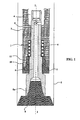
- FIG. 1 is a diagrammatic view in longitudinal section of a down hole motor like those used in oil prospecting.
- the down hole motor is placed at the end of a generally vertical drillstring, and is therefore located at the bottom of a drill hole 2. It generally comprises a tubular motor body 3 with an axial passage 4 and a drive shaft 5 rotatably mounted in the motor body 3.
- the drive shaft 5 is guided in the motor body 3 on the one hand by an axial thrust bearing 6 adapted to absorb forces in the axial direction, in particular for pushing the drive shaft 5 downward, and by a radial bearing 7 adapted to guide the drive shaft 5 radially in the motor body 3.
- the free end 5a of the drive shaft 5 extends out of the motor body 3 and is adapted to carry a drill bit 8 which, by virtue of the rotation of the drive shaft 5, produces the drill hole 2.
- the down hole motor 1 is driven in rotation by pressurized drilling mud injected from the surface through the axial passage 4, which drilling mud is fed to the drill bit 8 to extract the cuttings.
- the mixture of cuttings and drilling mud rises to the surface around the motor body 3 in the drill hole 2.
- the drive shaft 5 turns at a speed of about 100 to 300 revolutions per minute.
- the down hole motor 1 Because of its position very far away from the operators, deep at the bottom of the drill hole 2, the down hole motor 1 must be highly reliable to prevent the risk of jamming.
- the drive shaft 5 must be guided with great reliability, especially by the radial bearing 7.
- the drilling mud must also be prevented from penetrating into the clearance between the radial bearing 7 and a corresponding radial guide section 9 of the rotary shaft 5.
- a radial bearing 7 is produced whose dimensions are particularly precise so that the clearance between the radial bearing 7 and the radial guide section 9 is sufficiently small to oppose the penetration of abrasive particles contained in the drilling mud.
- the invention provides a radial bearing 7 and a radial guide section 9 whose surfaces have good anti-abrasion properties, provided by anti-abrasion materials that are particularly strong to oppose any abrasive effect of the drilling mud, the bearing body itself being of a material having good mechanical strength properties.
- a radial bearing 7 fastened into the motor body 3.
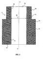
- the radial bearing 7 is therefore a tubular part in the form of a bush whose interior surface forms the guiding surface of the radial bearing 7 and whose exterior surface is conformed to fit into the motor body 3.
- the part 7 forming the radial bearing is therefore a tubular part, having a peripheral wall 7a surrounding an axial through-passage 7b.
- the peripheral wall 7a comprises a thicker distal section 7c and a thinner proximal section 7d, the two being concentric and having a continuous axial passage 7b of constant diameter.
- the outside diameter of the proximal section 7d is smaller than the outside diameter of the distal section 7c so as to fit into one tubular end of the motor body 3 as shown in figure 1 .
- the outside surface 7e of the proximal section 7d therefore constitutes an outside surface to be fixed into the motor body 3.
- the peripheral wall 7a includes a cylindrical interior surface 7g whose inside diameter D1 is perfectly adapted to receive with a small functional clearance the radial guide section 9 of the drive shaft 5 ( figure 1 ).
- the radial bearing 7 of the down hole motor in reality comprises a tubular radial bearing body 10, essentially of steel with high mechanical strength, such as a heat-treated alloy steel, and an anti-abrasion interior layer 11 forming the interior surface 7g.
- the bearing body 10 can advantageously be of carbon steel suitable for quenching containing chromium and molybdenum, for example 42CD4 steel according to the AFNOR French standard or AISI 4140 steel according to the international standard.
- the bearing body 10 can be made entirely of steel. However, in certain applications, the bearing body 10 can be partly of steel and partly of other materials, steel forming the metal base receiving the anti-abrasion interior layer 11.
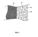
- the anti-abrasion interior layer 11 is based on grains of anti-abrasion material buried in a metal matrix.
- Figure 3 shows the structure of the anti-abrasion layer 11 to a larger scale: the grains 11c of anti-abrasion material are buried in the metal matrix 11d.
- the anti-abrasion material of the grains 11c is preferably chosen in the group consisting of tungsten carbide and titanium carbide.
- the metal matrix 11d advantageously consists of a nickel alloy having a high hardness.
- the interior surface 7g is a circular cylinder with a surface state whose roughness parameter Ra is less than or equal to 0.4 ⁇ m.
- the invention uses a laser-assisted facing process inside the tubular part forming the radial bearing body 10.
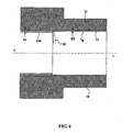
- Figure 4 shows the device used for implementing this method.
- a radial bearing body 10 is placed in a horizontal position, i.e. with its longitudinal axis I-I oriented horizontally, the radial bearing body 10 being held by a rotary spindle (not shown) that can drive it in rotation about its axis I-I as shown by the arrow 12.
- the radial bearing body 10 is an alloy steel body that has undergone heat treatment to harden it, like that shown in figure 2 .
- the device further comprises a facing head 13 with dimensions such that it can penetrate into the axial passage 7b of the radial bearing body 10 and adapted to spray onto a facing area 14 of the interior surface 7f of the radial bearing body 10 a mixture of metal matrix alloy powder and anti-abrasion material grains, in a radial jet 15, at the same time as a radial laser beam impinges on the facing area 14.
- the facing head 13 includes a radial conduit 13a with a powder sprayer nozzle in which the powder moves in a cyclone toward the outlet 13b.
- the facing head 13 is mounted at the end of an axial tube 13c the upstream end of which remains outside the radial bearing body 10.
- a laser source 16 for example a laser diode, or a CO 2 laser, or a YAG laser, or a fiber laser, produces a laser beam that propagates axially in the axial tube 13c and is deflected by a mirror 17 in the radial direction toward the outlet 13b of the facing head 13.
- An optical system guides the laser beam in the axial tube 13c and in the facing head 13 to focus it onto the facing area 14.
- the assembly formed by the facing head 13 and the laser source 16 can be moved axially along the axis I-I so that the facing area 14 can be moved with a helicoidal movement over all of the interior surface 7f of the radial bearing body 10 through a combination of the axial movement of the facing head 13 and the circular movement of the radial bearing body 10 about the axis I-I.
- the radial bearing body 10 initially has no anti-abrasion material layer and the facing operation produces the whole of the anti-abrasion layer 11.
- the exterior surface of the tubular radial bearing body 10 is held by a rotary spindle rotating about the horizontal axis I-I, the radial bearing body 10 having a cylindrical interior surface 7f.
- An anti-abrasion material layer 11 is applied directly to the interior surface 7f of the tubular radial bearing body 10 by laser-assisted facing by means of the facing nozzle 13. The layer is applied progressively by axial movement of the facing nozzle 13 and by rotation about the axis I-I of the radial bearing body 10 so that the facing area 14 occupies successively all the portions of the interior surface 7f of the radial bearing body 10.
- the anti-abrasion material layer is machined to produce a final cylindrical interior surface 7g having an appropriate diameter D1.
- Figure 6 shows the machining step, using a grinding tool or other tool 18 for removing material that is moved progressively in the axial direction I-I while the radial bearing body 10 is turned about the axis I-I.
- a grinding tool or other tool 18 for removing material that is moved progressively in the axial direction I-I while the radial bearing body 10 is turned about the axis I-I.
- an anti-abrasion material layer 11b having an initial thickness E1 of about 1 mm
- an anti-abrasion layer 11 having a final thickness EF of about 0.75 mm, the final interior surface 7g of which is perfectly cylindrical and coaxial and has a roughness parameter Ra that is preferably less than or equal to 0.4 ⁇ m.
- figure 5 shows the process of facing a radial bearing 7 to be reconditioned, to reestablish the exact shape of the interior surface 7g ( figure 2 ).
- the same means are used as in figure 4 , and those means are identified by the same reference numbers.
- the facing is effected by depositing a layer 11b on the surface 7f of a layer 11a to be repaired.
- the subsequent machining step shown in figure 6 is the same as before.
- a multilayer deposit can be formed in a number of successive passes of the facing nozzle 13 over the interior surface of the radial bearing body 10.
- the machining step is carried out to remove material, for example to a thickness of about 0.25 mm.
Landscapes
- Engineering & Computer Science (AREA)
- General Engineering & Computer Science (AREA)
- Mechanical Engineering (AREA)
- Mining & Mineral Resources (AREA)
- Life Sciences & Earth Sciences (AREA)
- Geology (AREA)
- Geochemistry & Mineralogy (AREA)
- General Life Sciences & Earth Sciences (AREA)
- Physics & Mathematics (AREA)
- Fluid Mechanics (AREA)
- Environmental & Geological Engineering (AREA)
- Chemical & Material Sciences (AREA)
- Ceramic Engineering (AREA)
- Sliding-Contact Bearings (AREA)
- Coating By Spraying Or Casting (AREA)
- Motor Or Generator Frames (AREA)
- Manufacture Of Motors, Generators (AREA)
- Shafts, Cranks, Connecting Bars, And Related Bearings (AREA)
Claims (11)
- Verfahren zur Herstellung eines Tiefbohr-Motor-Radiallagers (7) mit einer inneren Anti-Abrasions-Oberfläche (7g), wobei das Radiallager (7) einen rohrförmigen metallischen Radiallager-Körper (10) mit einer Befestigungsfläche (7e) aufweist, zu dessen Befestigung in einem Tiefbohr-Motor-Körper (3) und eine innere Anti-Abrasionsschicht (11) basierend auf Körnern (11c) eines Anti-Abrasions-Materiales, das in einer Metallmatrix (11d) eingebettet ist, wobei das Verfahren folgende Schritte enthält:a) Bereitstellen und Halten eines rohrförmigen Radiallager-Körpers (10), der eine anfängliche innere Oberfläche (7f) aufweist, und eine zentrale Passage (7b),b) Auftragen einer Anti-Abrasions-MaterialSchicht (11b) direkt auf die anfängliche innere Oberfläche (7f) des rohrförmigen Radial-Lager-Körpers (10) durch Laser-unterstütztes Aufbringen, wobei ein Laserstrahl in die zentrale Passage (7b) des Radiallager-Körpers (10) gerichtet wird, bis zu einem zugewandten Bereich (14) der anfänglichen inneren Oberfläche (7f), und wobei gleichzeitig auf die zugewandte Oberfläche (14) eine Mischung von Anti-Abrasions-Material-Körnern und Metallpulver aufgesprüht wird,c) nach Abkühlung, Bearbeiten der Anti-Abrasions-Material-Schicht (11b) zur Erzeugung der inneren Anti-Abrasions-Schicht (11), die eine endgültige zylindrische Innere Oberfläche (7g) mit einem geeigneten Innendurchmesser (D1) aufweist.
- Verfahren nach Anspruch 1, dadurch gekennzeichnet, dass während des Schrittes b) der Laserstrahl durch eine Laserquelle (16) erzeugt wird,
und die zugewandte Oberfläche (14) progressiv in den Radiallager-Körper (10) bewegt wird, um eine Anti-Abrasions-Material-Schicht (11b) von im wesentlichen gleichförmiger Dicke auf der anfänglichen inneren Oberfläche (7f) zu bilden. - Verfahren nach einem der Ansprüche 1 oder 2, dadurch gekennzeichnet, dass am Ende des Schrittes b) die von einem Laser-unterstützen Auftragungsprozess gebildete Anti-Abrasions-Material-Schicht (11b) eine Dicke (E1) von ungefähr 1 mm hat.
- Verfahren nach Anspruch 3, dadurch gekennzeichnet, dass am Ende des Schrittes c) die endgültige Anti-Abrasions-Material-Schicht (11) eine Dicke (EF) von ungefähr 0,75 mm hat.
- Verfahren nach Anspruch 4, dadurch gekennzeichnet, dass am Ende der Bearbeitung die endgültige innere Oberfläche (7g) einen Oberflächenzustand hat, dessen Rauheitsparameter (Ra) kleiner oder gleich 0,4 µm ist.
- Verfahren nach irgendeinem der Ansprüche 1 bis 5, dadurch gekennzeichnet, dass:- während des Schrittes a) der rohrförmige metallische Radiallager-Körper (10) keine innere Anti-Abrasions-Schicht hat,- während des Schrittes b) die Anti-Abrasions-Material-Schicht direkt auf den Metallteil des rohrförmigen Radiallager-Körpers (10) aufgebracht wird.
- Verfahren nach irgendeinem der Ansprüche 1 bis 5, dadurch gekennzeichnet, dass:- während des Schrittes a) der rohrförmige metallische Radiallager-Körper (10) eine innere Anti-Abrasions-Schicht (11a), die zu reparieren ist, enthält,- während des Schrittes b) die Anti-Abrasions-Material-Schicht auf die innere Anti-Abrasions-Schicht (11a), die zu reparieren ist, aufgebracht wird.
- Verfahren nach irgendeinem der Ansprüche 1 bis 7, dadurch gekennzeichnet, dass der rohrförmige Radiallager-Körper (10) im wesentlichen aus Stahl mit hoher mechanischer Festigkeit, wie z.B. eine wärmebehandelte Stahllegierung, ist.
- Verfahren nach irgendeinem der Ansprüche 1 bis 8, dadurch gekennzeichnet, dass:- das Anti-Abrasions-Material der Körner (11c) ausgewählt ist, aus der Gruppe, die Wolframcarbid und Titan-Carbid enthält,- wobei die Metallmatrix (11d) eine Nickellegierung ist.
- Tiefbohr-Motor-Radiallager (7) mit eine innere Anti-Abrasions-Oberfläche (7g), mit:- einem rohrförmigen Radiallager-Körper (10) aus Stahl mit hoher mechanischer Festigkeit, wie z.B. einer wärmebehandelten Stahllegierung,- einer inneren Anti-Abrasions-Schicht (11) basierend auf Anti-Abrasions-Material-Körnern (11c), die aus der Gruppe ausgewählt sind, die Wolframcarbid und Titan-Carbid enthält, wobei die Anti-Abrasions-Material-Körner (11c) in einer Nickellegierungsmatrix (11d) eingebettet sind,- wobei die innere Oberfläche (7g) ein kreisförmiger Zylinder ist, mit einem Oberflächenzustand, dessen Rauhigkeitsparameter kleiner oder gleich 0,4 µm ist.
- Tiefbohrungsmotor mit:- einem Motorkörper (3) mit einer axialen Passage (4), in der ein Radiallager (7) gemäß Anspruch 10 befestigt ist,- einer Antriebswelle (4) die ausgebildet ist, eine Bohrspitze (8) zu tragen und einen zylindrischen Abschnitt (9) aufweist, der mit einem geringen Spiel in das Radiallager (7) eingreift, wobei auch der zylindrische Abschnitt (9) eine äußere Anti-Abrasions-Schicht aufweist, die auf Anti-Abrasions-Körnern basiert, die in einer Nickellegierungsmatrix eingebettet sind.
Applications Claiming Priority (1)
| Application Number | Priority Date | Filing Date | Title |
|---|---|---|---|
| PCT/IB2008/051776 WO2009098549A1 (en) | 2008-02-08 | 2008-02-08 | Method and device for manufacturing a down hole motor radial bearing |
Publications (2)
| Publication Number | Publication Date |
|---|---|
| EP2245255A1 EP2245255A1 (de) | 2010-11-03 |
| EP2245255B1 true EP2245255B1 (de) | 2014-10-22 |
Family
ID=39764934
Family Applications (1)
| Application Number | Title | Priority Date | Filing Date |
|---|---|---|---|
| EP08763070.3A Not-in-force EP2245255B1 (de) | 2008-02-08 | 2008-02-08 | Verfahren und vorrichtung zur herstellung eines bohrlochmotorradiallagers |
Country Status (8)
| Country | Link |
|---|---|
| US (2) | US8795794B2 (de) |
| EP (1) | EP2245255B1 (de) |
| JP (1) | JP5373824B2 (de) |
| AU (1) | AU2008350061B2 (de) |
| CA (1) | CA2715041C (de) |
| DE (1) | DE08763070T1 (de) |
| DK (1) | DK2245255T3 (de) |
| WO (1) | WO2009098549A1 (de) |
Families Citing this family (6)
| Publication number | Priority date | Publication date | Assignee | Title |
|---|---|---|---|---|
| US9803689B2 (en) * | 2005-06-21 | 2017-10-31 | United Machine Works, Inc. | Bearing tools and process |
| US8535408B2 (en) | 2009-04-29 | 2013-09-17 | Reedhycalog, L.P. | High thermal conductivity hardfacing |
| SG10201405118UA (en) * | 2013-08-21 | 2015-03-30 | Tru Marine Pte Ltd | Refurbished bearing and method of repairing a bearing |
| US9279289B2 (en) | 2013-10-03 | 2016-03-08 | Renegade Manufacturing, LLC | Combination mud motor flow diverter and tiled bearing, and bearing assemblies including same |
| US10920826B2 (en) | 2017-03-17 | 2021-02-16 | Halliburton Energy Services, Inc. | Radial bearing with wear resistant inserts and a wear resistant coating |
| CN116100170A (zh) * | 2022-11-10 | 2023-05-12 | 大连理工大学 | 一种超快激光高质高效加工斜孔方法 |
Family Cites Families (36)
| Publication number | Priority date | Publication date | Assignee | Title |
|---|---|---|---|---|
| AT299865B (de) * | 1967-12-22 | 1972-07-10 | Schloemann Ag | Walzenlagerung |
| US3936247A (en) * | 1973-08-15 | 1976-02-03 | Smith International, Inc. | Floating flow restrictors for fluid motors |
| US4273159A (en) * | 1978-03-16 | 1981-06-16 | Smith International, Inc. | Earth boring apparatus with multiple welds |
| US4240683A (en) * | 1979-01-12 | 1980-12-23 | Smith International, Inc. | Adjustable bearing assembly |
| US4277108A (en) * | 1979-01-29 | 1981-07-07 | Reed Tool Company | Hard surfacing for oil well tools |
| US4495907A (en) * | 1983-01-18 | 1985-01-29 | Cummins Engine Company, Inc. | Combustion chamber components for internal combustion engines |
| US4592252A (en) | 1984-07-23 | 1986-06-03 | Cdp, Ltd. | Rolling cutters for drill bits, and processes to produce same |
| JPS63265617A (ja) * | 1986-12-19 | 1988-11-02 | Hitachi Metals Ltd | 耐摩耗耐食性複合シリンダ |
| US4764036A (en) * | 1987-05-14 | 1988-08-16 | Smith International, Inc. | PCD enhanced radial bearing |
| US4819517A (en) * | 1988-07-05 | 1989-04-11 | Edward Vezirian | Selected bearing couple for a rock bit journal and method for making same |
| US4868069A (en) | 1988-08-11 | 1989-09-19 | The Dexter Corporation | Abrasion-resistant coating |
| GB2228011B (en) * | 1989-02-01 | 1993-06-16 | Nippon Dia Clevite Co | A bearing material |
| US4958058A (en) * | 1989-02-08 | 1990-09-18 | General Electric Company | Transverse flow laser spray nozzle |
| US4923511A (en) | 1989-06-29 | 1990-05-08 | W S Alloys, Inc. | Tungsten carbide hardfacing powders and compositions thereof for plasma-transferred-arc deposition |
| JPH05149325A (ja) * | 1991-11-21 | 1993-06-15 | Hitachi Koki Co Ltd | 動圧軸受 |
| US5458460A (en) | 1993-03-18 | 1995-10-17 | Hitachi, Ltd. | Drainage pump and a hydraulic turbine incorporating a bearing member, and a method of manufacturing the bearing member |
| JP3271363B2 (ja) * | 1992-03-18 | 2002-04-02 | 株式会社日立製作所 | 軸受装置、その軸受装置を備えた排水ポンプ及び水車、並びに軸受装置の製造方法 |
| US5663512A (en) | 1994-11-21 | 1997-09-02 | Baker Hughes Inc. | Hardfacing composition for earth-boring bits |
| US5598818A (en) * | 1996-01-26 | 1997-02-04 | Spx Corporation | Method of providing a cylinder bore liner in an internal combustion engine |
| US6309762B1 (en) * | 1997-05-08 | 2001-10-30 | Conforma Clad | Replaceable wear resistant surfaces |
| US6582126B2 (en) * | 1998-06-03 | 2003-06-24 | Northmonte Partners, Lp | Bearing surface with improved wear resistance and method for making same |
| US6117493A (en) | 1998-06-03 | 2000-09-12 | Northmonte Partners, L.P. | Bearing with improved wear resistance and method for making same |
| JP2000017821A (ja) * | 1998-07-01 | 2000-01-18 | Eimubaru:Kk | 床パネル及び床パネル補強方法 |
| JP2000136827A (ja) * | 1998-11-02 | 2000-05-16 | Shinshu Ceramics:Kk | 摺動部材の製造方法及び摺動部材 |
| DE19907105A1 (de) * | 1999-02-19 | 2000-08-31 | Volkswagen Ag | Verfahren und Vorrichtung zum Herstellen von verschleißfesten, tribologischen Zylinderlaufflächen |
| JP2002139043A (ja) * | 2000-11-06 | 2002-05-17 | Ricoh Co Ltd | 動圧軸受及びポリゴンスキャナ及びこれらの製造方法 |
| US20020155957A1 (en) | 2001-02-14 | 2002-10-24 | Danly, James C. | Sintered anti-friction bearing surface |
| JP2002256963A (ja) * | 2001-03-05 | 2002-09-11 | Suzuki Motor Corp | 内燃機関用シリンダブロックの製造方法 |
| JP2005024094A (ja) | 2003-06-10 | 2005-01-27 | Ntn Corp | すべり軸受 |
| JP2006002937A (ja) | 2004-05-20 | 2006-01-05 | Minebea Co Ltd | 流体動圧軸受装置およびその製造方法、スピンドルモータ、および記録ディスク駆動装置 |
| JP4087376B2 (ja) * | 2004-12-17 | 2008-05-21 | 株式会社日本製鋼所 | 二軸スクリュ混練装置用のシリンダ |
| US20060185773A1 (en) * | 2005-02-22 | 2006-08-24 | Canadian Oil Sands Limited | Lightweight wear-resistant weld overlay |
| US20110131810A1 (en) * | 2005-06-21 | 2011-06-09 | Von Gynz-Rekowski Gunther Hh | Process for manufacturing a bearing |
| US7882638B2 (en) * | 2005-06-21 | 2011-02-08 | Ashmin Lc | Process for manufacturing a bearing |
| US7632323B2 (en) * | 2005-12-29 | 2009-12-15 | Schlumberger Technology Corporation | Reducing abrasive wear in abrasion resistant coatings |
| US20130182982A1 (en) * | 2012-01-17 | 2013-07-18 | Dennis Tool Company | Carbide wear surface and method of manufacture |
-
2008
- 2008-02-08 EP EP08763070.3A patent/EP2245255B1/de not_active Not-in-force
- 2008-02-08 AU AU2008350061A patent/AU2008350061B2/en not_active Ceased
- 2008-02-08 US US12/811,548 patent/US8795794B2/en not_active Expired - Fee Related
- 2008-02-08 JP JP2010545568A patent/JP5373824B2/ja not_active Expired - Fee Related
- 2008-02-08 CA CA2715041A patent/CA2715041C/en not_active Expired - Fee Related
- 2008-02-08 WO PCT/IB2008/051776 patent/WO2009098549A1/en not_active Ceased
- 2008-02-08 DE DE08763070T patent/DE08763070T1/de active Pending
- 2008-02-08 DK DK08763070.3T patent/DK2245255T3/en active
-
2014
- 2014-06-27 US US14/317,552 patent/US9371858B2/en not_active Expired - Fee Related
Also Published As
| Publication number | Publication date |
|---|---|
| AU2008350061B2 (en) | 2014-09-04 |
| US9371858B2 (en) | 2016-06-21 |
| AU2008350061A1 (en) | 2009-08-13 |
| EP2245255A1 (de) | 2010-11-03 |
| JP5373824B2 (ja) | 2013-12-18 |
| US8795794B2 (en) | 2014-08-05 |
| CA2715041A1 (en) | 2009-08-13 |
| WO2009098549A1 (en) | 2009-08-13 |
| DK2245255T3 (en) | 2015-01-19 |
| US20140307991A1 (en) | 2014-10-16 |
| CA2715041C (en) | 2015-06-16 |
| JP2011514486A (ja) | 2011-05-06 |
| US20100288559A1 (en) | 2010-11-18 |
| DE08763070T1 (de) | 2011-05-05 |
Similar Documents
| Publication | Publication Date | Title |
|---|---|---|
| US9371858B2 (en) | Method and device for manufacturing a down hole motor radial bearing | |
| US4781770A (en) | Process for laser hardfacing drill bit cones having hard cutter inserts | |
| AU609123B2 (en) | Improved bearing structure for downhole motors | |
| US4303137A (en) | Method for making a cone for a rock bit and product | |
| US20100078224A1 (en) | Ball hole welding using the friction stir welding (fsw) process | |
| EP2963305B1 (de) | Verfahren zur herstellung einer hohlwalze, durch solch ein verfahren herstellbare hohlwalze und wälzlager mit solch einer walze | |
| US4127043A (en) | Rock bit with welded bearing pins | |
| NO338539B1 (no) | Fremgangsmåte og verktøy for tilvirkning av rør | |
| US5759641A (en) | Method of applying strengthening coatings to metallic or metal-containing surfaces | |
| CN113276068A (zh) | 插入式工具和用于制造插入式工具的方法 | |
| AU627583B2 (en) | Manufacture of poppet valves by spray deposition | |
| CN103769794A (zh) | 一种无缝钢管轧机穿孔顶头表面强化方法 | |
| US20160076128A1 (en) | Thermal Spray Coating for Mechanical Face Seals | |
| CN106574355A (zh) | 旋转切割单元的制造有添加层的砧座 | |
| US9803689B2 (en) | Bearing tools and process | |
| US5531633A (en) | Method of machining a metal workpiece | |
| JP7612611B2 (ja) | ダイヤモンド対ダイヤモンド反応材料軸受係合のための材料処理 | |
| US20210340820A1 (en) | Steering pad apparatus and related methods | |
| RU2347669C1 (ru) | Способ импульсного упрочнения резьбы | |
| CA1121331A (en) | Method for making rock bits | |
| RU2347668C1 (ru) | Инструмент для импульсного упрочнения резьбы | |
| CN116200581A (zh) | 轴承钢的表面强化方法和轴承钢 | |
| RU2303513C1 (ru) | Способ комбинированной чистовой и упрочняющей обработки | |
| RU2297315C1 (ru) | Способ поверхностной пластической обработки инструментом с деформирующей пружиной | |
| JP2001241433A (ja) | 動圧軸受における動圧発生溝の加工方法 |
Legal Events
| Date | Code | Title | Description |
|---|---|---|---|
| PUAI | Public reference made under article 153(3) epc to a published international application that has entered the european phase |
Free format text: ORIGINAL CODE: 0009012 |
|
| 17P | Request for examination filed |
Effective date: 20100803 |
|
| AK | Designated contracting states |
Kind code of ref document: A1 Designated state(s): AT BE BG CH CY CZ DE DK EE ES FI FR GB GR HR HU IE IS IT LI LT LU LV MC MT NL NO PL PT RO SE SI SK TR |
|
| AX | Request for extension of the european patent |
Extension state: AL BA MK RS |
|
| DET | De: translation of patent claims | ||
| REG | Reference to a national code |
Ref country code: DE Ref legal event code: R210 Ref document number: 602008035008 Country of ref document: DE Effective date: 20110505 |
|
| DAX | Request for extension of the european patent (deleted) | ||
| REG | Reference to a national code |
Ref country code: FR Ref legal event code: EL |
|
| GRAP | Despatch of communication of intention to grant a patent |
Free format text: ORIGINAL CODE: EPIDOSNIGR1 |
|
| INTG | Intention to grant announced |
Effective date: 20131218 |
|
| GRAP | Despatch of communication of intention to grant a patent |
Free format text: ORIGINAL CODE: EPIDOSNIGR1 |
|
| INTG | Intention to grant announced |
Effective date: 20140515 |
|
| GRAS | Grant fee paid |
Free format text: ORIGINAL CODE: EPIDOSNIGR3 |
|
| GRAA | (expected) grant |
Free format text: ORIGINAL CODE: 0009210 |
|
| AK | Designated contracting states |
Kind code of ref document: B1 Designated state(s): AT BE BG CH CY CZ DE DK EE ES FI FR GB GR HR HU IE IS IT LI LT LU LV MC MT NL NO PL PT RO SE SI SK TR |
|
| REG | Reference to a national code |
Ref country code: GB Ref legal event code: FG4D |
|
| REG | Reference to a national code |
Ref country code: DE Ref legal event code: R082 Ref document number: 602008035008 Country of ref document: DE Representative=s name: VON BUELOW & TAMADA PATENTANWALTSGESELLSCHAFT, DE Ref country code: DE Ref legal event code: R082 Ref document number: 602008035008 Country of ref document: DE |
|
| REG | Reference to a national code |
Ref country code: CH Ref legal event code: EP |
|
| REG | Reference to a national code |
Ref country code: AT Ref legal event code: REF Ref document number: 692758 Country of ref document: AT Kind code of ref document: T Effective date: 20141115 |
|
| REG | Reference to a national code |
Ref country code: IE Ref legal event code: FG4D |
|
| REG | Reference to a national code |
Ref country code: DE Ref legal event code: R096 Ref document number: 602008035008 Country of ref document: DE Effective date: 20141204 |
|
| REG | Reference to a national code |
Ref country code: CH Ref legal event code: NV Representative=s name: WAGNER PATENT AG, CH |
|
| REG | Reference to a national code |
Ref country code: DK Ref legal event code: T3 Effective date: 20150115 |
|
| REG | Reference to a national code |
Ref country code: RO Ref legal event code: EPE |
|
| REG | Reference to a national code |
Ref country code: SE Ref legal event code: TRGR |
|
| REG | Reference to a national code |
Ref country code: NL Ref legal event code: T3 |
|
| REG | Reference to a national code |
Ref country code: LT Ref legal event code: MG4D |
|
| REG | Reference to a national code |
Ref country code: NO Ref legal event code: T2 Effective date: 20141022 |
|
| PG25 | Lapsed in a contracting state [announced via postgrant information from national office to epo] |
Ref country code: FI Free format text: LAPSE BECAUSE OF FAILURE TO SUBMIT A TRANSLATION OF THE DESCRIPTION OR TO PAY THE FEE WITHIN THE PRESCRIBED TIME-LIMIT Effective date: 20141022 Ref country code: PT Free format text: LAPSE BECAUSE OF FAILURE TO SUBMIT A TRANSLATION OF THE DESCRIPTION OR TO PAY THE FEE WITHIN THE PRESCRIBED TIME-LIMIT Effective date: 20150223 Ref country code: ES Free format text: LAPSE BECAUSE OF FAILURE TO SUBMIT A TRANSLATION OF THE DESCRIPTION OR TO PAY THE FEE WITHIN THE PRESCRIBED TIME-LIMIT Effective date: 20141022 Ref country code: LT Free format text: LAPSE BECAUSE OF FAILURE TO SUBMIT A TRANSLATION OF THE DESCRIPTION OR TO PAY THE FEE WITHIN THE PRESCRIBED TIME-LIMIT Effective date: 20141022 Ref country code: IS Free format text: LAPSE BECAUSE OF FAILURE TO SUBMIT A TRANSLATION OF THE DESCRIPTION OR TO PAY THE FEE WITHIN THE PRESCRIBED TIME-LIMIT Effective date: 20150222 |
|
| PGFP | Annual fee paid to national office [announced via postgrant information from national office to epo] |
Ref country code: IE Payment date: 20150109 Year of fee payment: 8 |
|
| PG25 | Lapsed in a contracting state [announced via postgrant information from national office to epo] |
Ref country code: GR Free format text: LAPSE BECAUSE OF FAILURE TO SUBMIT A TRANSLATION OF THE DESCRIPTION OR TO PAY THE FEE WITHIN THE PRESCRIBED TIME-LIMIT Effective date: 20150123 Ref country code: HR Free format text: LAPSE BECAUSE OF FAILURE TO SUBMIT A TRANSLATION OF THE DESCRIPTION OR TO PAY THE FEE WITHIN THE PRESCRIBED TIME-LIMIT Effective date: 20141022 Ref country code: LV Free format text: LAPSE BECAUSE OF FAILURE TO SUBMIT A TRANSLATION OF THE DESCRIPTION OR TO PAY THE FEE WITHIN THE PRESCRIBED TIME-LIMIT Effective date: 20141022 Ref country code: CY Free format text: LAPSE BECAUSE OF FAILURE TO SUBMIT A TRANSLATION OF THE DESCRIPTION OR TO PAY THE FEE WITHIN THE PRESCRIBED TIME-LIMIT Effective date: 20141022 Ref country code: PL Free format text: LAPSE BECAUSE OF FAILURE TO SUBMIT A TRANSLATION OF THE DESCRIPTION OR TO PAY THE FEE WITHIN THE PRESCRIBED TIME-LIMIT Effective date: 20141022 |
|
| PGFP | Annual fee paid to national office [announced via postgrant information from national office to epo] |
Ref country code: TR Payment date: 20150120 Year of fee payment: 8 |
|
| REG | Reference to a national code |
Ref country code: DE Ref legal event code: R097 Ref document number: 602008035008 Country of ref document: DE |
|
| PG25 | Lapsed in a contracting state [announced via postgrant information from national office to epo] |
Ref country code: EE Free format text: LAPSE BECAUSE OF FAILURE TO SUBMIT A TRANSLATION OF THE DESCRIPTION OR TO PAY THE FEE WITHIN THE PRESCRIBED TIME-LIMIT Effective date: 20141022 Ref country code: SK Free format text: LAPSE BECAUSE OF FAILURE TO SUBMIT A TRANSLATION OF THE DESCRIPTION OR TO PAY THE FEE WITHIN THE PRESCRIBED TIME-LIMIT Effective date: 20141022 |
|
| PLBE | No opposition filed within time limit |
Free format text: ORIGINAL CODE: 0009261 |
|
| STAA | Information on the status of an ep patent application or granted ep patent |
Free format text: STATUS: NO OPPOSITION FILED WITHIN TIME LIMIT |
|
| 26N | No opposition filed |
Effective date: 20150723 |
|
| PG25 | Lapsed in a contracting state [announced via postgrant information from national office to epo] |
Ref country code: MC Free format text: LAPSE BECAUSE OF FAILURE TO SUBMIT A TRANSLATION OF THE DESCRIPTION OR TO PAY THE FEE WITHIN THE PRESCRIBED TIME-LIMIT Effective date: 20141022 |
|
| REG | Reference to a national code |
Ref country code: FR Ref legal event code: PLFP Year of fee payment: 9 |
|
| PG25 | Lapsed in a contracting state [announced via postgrant information from national office to epo] |
Ref country code: SI Free format text: LAPSE BECAUSE OF FAILURE TO SUBMIT A TRANSLATION OF THE DESCRIPTION OR TO PAY THE FEE WITHIN THE PRESCRIBED TIME-LIMIT Effective date: 20141022 |
|
| REG | Reference to a national code |
Ref country code: AT Ref legal event code: UEP Ref document number: 692758 Country of ref document: AT Kind code of ref document: T Effective date: 20141022 |
|
| REG | Reference to a national code |
Ref country code: IE Ref legal event code: MM4A |
|
| REG | Reference to a national code |
Ref country code: FR Ref legal event code: PLFP Year of fee payment: 10 |
|
| PG25 | Lapsed in a contracting state [announced via postgrant information from national office to epo] |
Ref country code: MT Free format text: LAPSE BECAUSE OF FAILURE TO SUBMIT A TRANSLATION OF THE DESCRIPTION OR TO PAY THE FEE WITHIN THE PRESCRIBED TIME-LIMIT Effective date: 20141022 |
|
| PG25 | Lapsed in a contracting state [announced via postgrant information from national office to epo] |
Ref country code: IE Free format text: LAPSE BECAUSE OF NON-PAYMENT OF DUE FEES Effective date: 20160208 |
|
| PG25 | Lapsed in a contracting state [announced via postgrant information from national office to epo] |
Ref country code: BG Free format text: LAPSE BECAUSE OF FAILURE TO SUBMIT A TRANSLATION OF THE DESCRIPTION OR TO PAY THE FEE WITHIN THE PRESCRIBED TIME-LIMIT Effective date: 20141022 Ref country code: HU Free format text: LAPSE BECAUSE OF FAILURE TO SUBMIT A TRANSLATION OF THE DESCRIPTION OR TO PAY THE FEE WITHIN THE PRESCRIBED TIME-LIMIT; INVALID AB INITIO Effective date: 20080208 |
|
| REG | Reference to a national code |
Ref country code: FR Ref legal event code: PLFP Year of fee payment: 11 |
|
| PGFP | Annual fee paid to national office [announced via postgrant information from national office to epo] |
Ref country code: FR Payment date: 20181221 Year of fee payment: 12 |
|
| PGFP | Annual fee paid to national office [announced via postgrant information from national office to epo] |
Ref country code: LU Payment date: 20190218 Year of fee payment: 12 Ref country code: NL Payment date: 20190214 Year of fee payment: 12 |
|
| PGFP | Annual fee paid to national office [announced via postgrant information from national office to epo] |
Ref country code: RO Payment date: 20190207 Year of fee payment: 12 Ref country code: CZ Payment date: 20190118 Year of fee payment: 12 Ref country code: GB Payment date: 20190228 Year of fee payment: 12 Ref country code: IT Payment date: 20190212 Year of fee payment: 12 Ref country code: CH Payment date: 20190225 Year of fee payment: 12 Ref country code: NO Payment date: 20181228 Year of fee payment: 12 |
|
| PGFP | Annual fee paid to national office [announced via postgrant information from national office to epo] |
Ref country code: DK Payment date: 20190212 Year of fee payment: 12 Ref country code: SE Payment date: 20190219 Year of fee payment: 12 Ref country code: AT Payment date: 20190207 Year of fee payment: 12 Ref country code: BE Payment date: 20190123 Year of fee payment: 12 |
|
| PGFP | Annual fee paid to national office [announced via postgrant information from national office to epo] |
Ref country code: DE Payment date: 20190412 Year of fee payment: 12 |
|
| REG | Reference to a national code |
Ref country code: DE Ref legal event code: R119 Ref document number: 602008035008 Country of ref document: DE |
|
| REG | Reference to a national code |
Ref country code: DK Ref legal event code: EBP Effective date: 20200229 |
|
| REG | Reference to a national code |
Ref country code: NO Ref legal event code: MMEP |
|
| REG | Reference to a national code |
Ref country code: SE Ref legal event code: EUG |
|
| REG | Reference to a national code |
Ref country code: CH Ref legal event code: PL |
|
| REG | Reference to a national code |
Ref country code: NL Ref legal event code: MM Effective date: 20200301 |
|
| REG | Reference to a national code |
Ref country code: AT Ref legal event code: MM01 Ref document number: 692758 Country of ref document: AT Kind code of ref document: T Effective date: 20200208 |
|
| GBPC | Gb: european patent ceased through non-payment of renewal fee |
Effective date: 20200208 |
|
| REG | Reference to a national code |
Ref country code: BE Ref legal event code: MM Effective date: 20200229 |
|
| PG25 | Lapsed in a contracting state [announced via postgrant information from national office to epo] |
Ref country code: LU Free format text: LAPSE BECAUSE OF NON-PAYMENT OF DUE FEES Effective date: 20200208 Ref country code: NO Free format text: LAPSE BECAUSE OF NON-PAYMENT OF DUE FEES Effective date: 20200229 Ref country code: RO Free format text: LAPSE BECAUSE OF NON-PAYMENT OF DUE FEES Effective date: 20200208 Ref country code: CZ Free format text: LAPSE BECAUSE OF NON-PAYMENT OF DUE FEES Effective date: 20200208 Ref country code: SE Free format text: LAPSE BECAUSE OF NON-PAYMENT OF DUE FEES Effective date: 20200209 |
|
| PG25 | Lapsed in a contracting state [announced via postgrant information from national office to epo] |
Ref country code: AT Free format text: LAPSE BECAUSE OF NON-PAYMENT OF DUE FEES Effective date: 20200208 Ref country code: CH Free format text: LAPSE BECAUSE OF NON-PAYMENT OF DUE FEES Effective date: 20200229 Ref country code: LI Free format text: LAPSE BECAUSE OF NON-PAYMENT OF DUE FEES Effective date: 20200229 |
|
| PG25 | Lapsed in a contracting state [announced via postgrant information from national office to epo] |
Ref country code: NL Free format text: LAPSE BECAUSE OF NON-PAYMENT OF DUE FEES Effective date: 20200301 |
|
| PG25 | Lapsed in a contracting state [announced via postgrant information from national office to epo] |
Ref country code: DE Free format text: LAPSE BECAUSE OF NON-PAYMENT OF DUE FEES Effective date: 20200901 Ref country code: DK Free format text: LAPSE BECAUSE OF NON-PAYMENT OF DUE FEES Effective date: 20200229 Ref country code: GB Free format text: LAPSE BECAUSE OF NON-PAYMENT OF DUE FEES Effective date: 20200208 Ref country code: FR Free format text: LAPSE BECAUSE OF NON-PAYMENT OF DUE FEES Effective date: 20200229 |
|
| PG25 | Lapsed in a contracting state [announced via postgrant information from national office to epo] |
Ref country code: BE Free format text: LAPSE BECAUSE OF NON-PAYMENT OF DUE FEES Effective date: 20200229 |
|
| PG25 | Lapsed in a contracting state [announced via postgrant information from national office to epo] |
Ref country code: IT Free format text: LAPSE BECAUSE OF NON-PAYMENT OF DUE FEES Effective date: 20200208 |
|
| PG25 | Lapsed in a contracting state [announced via postgrant information from national office to epo] |
Ref country code: TR Free format text: LAPSE BECAUSE OF NON-PAYMENT OF DUE FEES Effective date: 20160208 |