EP2244904B1 - Stufenloses getriebe mit bremse - Google Patents
Stufenloses getriebe mit bremse Download PDFInfo
- Publication number
- EP2244904B1 EP2244904B1 EP09701499.7A EP09701499A EP2244904B1 EP 2244904 B1 EP2244904 B1 EP 2244904B1 EP 09701499 A EP09701499 A EP 09701499A EP 2244904 B1 EP2244904 B1 EP 2244904B1
- Authority
- EP
- European Patent Office
- Prior art keywords
- brake
- transmission
- coupled
- rotary
- ratio
- Prior art date
- Legal status (The legal status is an assumption and is not a legal conclusion. Google has not performed a legal analysis and makes no representation as to the accuracy of the status listed.)
- Active
Links
- 230000005540 biological transmission Effects 0.000 title claims description 83
- 230000007935 neutral effect Effects 0.000 claims description 23
- 230000007246 mechanism Effects 0.000 claims description 19
- 230000008878 coupling Effects 0.000 claims 1
- 238000010168 coupling process Methods 0.000 claims 1
- 238000005859 coupling reaction Methods 0.000 claims 1
- 238000010276 construction Methods 0.000 description 2
- 230000000750 progressive effect Effects 0.000 description 2
- 238000005096 rolling process Methods 0.000 description 2
- 230000001133 acceleration Effects 0.000 description 1
- 230000001174 ascending effect Effects 0.000 description 1
- 238000002485 combustion reaction Methods 0.000 description 1
- 230000006835 compression Effects 0.000 description 1
- 238000007906 compression Methods 0.000 description 1
- 230000036461 convulsion Effects 0.000 description 1
- 238000002360 preparation method Methods 0.000 description 1
- 230000000717 retained effect Effects 0.000 description 1
- 238000003466 welding Methods 0.000 description 1
Images


Classifications
-
- F—MECHANICAL ENGINEERING; LIGHTING; HEATING; WEAPONS; BLASTING
- F16—ENGINEERING ELEMENTS AND UNITS; GENERAL MEASURES FOR PRODUCING AND MAINTAINING EFFECTIVE FUNCTIONING OF MACHINES OR INSTALLATIONS; THERMAL INSULATION IN GENERAL
- F16H—GEARING
- F16H37/00—Combinations of mechanical gearings, not provided for in groups F16H1/00 - F16H35/00
- F16H37/02—Combinations of mechanical gearings, not provided for in groups F16H1/00 - F16H35/00 comprising essentially only toothed or friction gearings
- F16H37/06—Combinations of mechanical gearings, not provided for in groups F16H1/00 - F16H35/00 comprising essentially only toothed or friction gearings with a plurality of driving or driven shafts; with arrangements for dividing torque between two or more intermediate shafts
- F16H37/08—Combinations of mechanical gearings, not provided for in groups F16H1/00 - F16H35/00 comprising essentially only toothed or friction gearings with a plurality of driving or driven shafts; with arrangements for dividing torque between two or more intermediate shafts with differential gearing
- F16H37/0833—Combinations of mechanical gearings, not provided for in groups F16H1/00 - F16H35/00 comprising essentially only toothed or friction gearings with a plurality of driving or driven shafts; with arrangements for dividing torque between two or more intermediate shafts with differential gearing with arrangements for dividing torque between two or more intermediate shafts, i.e. with two or more internal power paths
- F16H37/084—Combinations of mechanical gearings, not provided for in groups F16H1/00 - F16H35/00 comprising essentially only toothed or friction gearings with a plurality of driving or driven shafts; with arrangements for dividing torque between two or more intermediate shafts with differential gearing with arrangements for dividing torque between two or more intermediate shafts, i.e. with two or more internal power paths at least one power path being a continuously variable transmission, i.e. CVT
-
- B—PERFORMING OPERATIONS; TRANSPORTING
- B60—VEHICLES IN GENERAL
- B60K—ARRANGEMENT OR MOUNTING OF PROPULSION UNITS OR OF TRANSMISSIONS IN VEHICLES; ARRANGEMENT OR MOUNTING OF PLURAL DIVERSE PRIME-MOVERS IN VEHICLES; AUXILIARY DRIVES FOR VEHICLES; INSTRUMENTATION OR DASHBOARDS FOR VEHICLES; ARRANGEMENTS IN CONNECTION WITH COOLING, AIR INTAKE, GAS EXHAUST OR FUEL SUPPLY OF PROPULSION UNITS IN VEHICLES
- B60K17/00—Arrangement or mounting of transmissions in vehicles
- B60K17/04—Arrangement or mounting of transmissions in vehicles characterised by arrangement, location, or kind of gearing
- B60K17/043—Transmission unit disposed in on near the vehicle wheel, or between the differential gear unit and the wheel
- B60K17/046—Transmission unit disposed in on near the vehicle wheel, or between the differential gear unit and the wheel with planetary gearing having orbital motion
-
- B—PERFORMING OPERATIONS; TRANSPORTING
- B60—VEHICLES IN GENERAL
- B60T—VEHICLE BRAKE CONTROL SYSTEMS OR PARTS THEREOF; BRAKE CONTROL SYSTEMS OR PARTS THEREOF, IN GENERAL; ARRANGEMENT OF BRAKING ELEMENTS ON VEHICLES IN GENERAL; PORTABLE DEVICES FOR PREVENTING UNWANTED MOVEMENT OF VEHICLES; VEHICLE MODIFICATIONS TO FACILITATE COOLING OF BRAKES
- B60T7/00—Brake-action initiating means
- B60T7/12—Brake-action initiating means for automatic initiation; for initiation not subject to will of driver or passenger
- B60T7/122—Brake-action initiating means for automatic initiation; for initiation not subject to will of driver or passenger for locking of reverse movement
-
- B—PERFORMING OPERATIONS; TRANSPORTING
- B60—VEHICLES IN GENERAL
- B60W—CONJOINT CONTROL OF VEHICLE SUB-UNITS OF DIFFERENT TYPE OR DIFFERENT FUNCTION; CONTROL SYSTEMS SPECIALLY ADAPTED FOR HYBRID VEHICLES; ROAD VEHICLE DRIVE CONTROL SYSTEMS FOR PURPOSES NOT RELATED TO THE CONTROL OF A PARTICULAR SUB-UNIT
- B60W10/00—Conjoint control of vehicle sub-units of different type or different function
- B60W10/10—Conjoint control of vehicle sub-units of different type or different function including control of change-speed gearings
- B60W10/101—Infinitely variable gearings
-
- B—PERFORMING OPERATIONS; TRANSPORTING
- B60—VEHICLES IN GENERAL
- B60W—CONJOINT CONTROL OF VEHICLE SUB-UNITS OF DIFFERENT TYPE OR DIFFERENT FUNCTION; CONTROL SYSTEMS SPECIALLY ADAPTED FOR HYBRID VEHICLES; ROAD VEHICLE DRIVE CONTROL SYSTEMS FOR PURPOSES NOT RELATED TO THE CONTROL OF A PARTICULAR SUB-UNIT
- B60W10/00—Conjoint control of vehicle sub-units of different type or different function
- B60W10/18—Conjoint control of vehicle sub-units of different type or different function including control of braking systems
-
- B—PERFORMING OPERATIONS; TRANSPORTING
- B60—VEHICLES IN GENERAL
- B60W—CONJOINT CONTROL OF VEHICLE SUB-UNITS OF DIFFERENT TYPE OR DIFFERENT FUNCTION; CONTROL SYSTEMS SPECIALLY ADAPTED FOR HYBRID VEHICLES; ROAD VEHICLE DRIVE CONTROL SYSTEMS FOR PURPOSES NOT RELATED TO THE CONTROL OF A PARTICULAR SUB-UNIT
- B60W30/00—Purposes of road vehicle drive control systems not related to the control of a particular sub-unit, e.g. of systems using conjoint control of vehicle sub-units
- B60W30/18—Propelling the vehicle
- B60W30/18181—Propulsion control with common controlling member for different functions
-
- F—MECHANICAL ENGINEERING; LIGHTING; HEATING; WEAPONS; BLASTING
- F16—ENGINEERING ELEMENTS AND UNITS; GENERAL MEASURES FOR PRODUCING AND MAINTAINING EFFECTIVE FUNCTIONING OF MACHINES OR INSTALLATIONS; THERMAL INSULATION IN GENERAL
- F16D—COUPLINGS FOR TRANSMITTING ROTATION; CLUTCHES; BRAKES
- F16D55/00—Brakes with substantially-radial braking surfaces pressed together in axial direction, e.g. disc brakes
- F16D55/02—Brakes with substantially-radial braking surfaces pressed together in axial direction, e.g. disc brakes with axially-movable discs or pads pressed against axially-located rotating members
- F16D55/22—Brakes with substantially-radial braking surfaces pressed together in axial direction, e.g. disc brakes with axially-movable discs or pads pressed against axially-located rotating members by clamping an axially-located rotating disc between movable braking members, e.g. movable brake discs or brake pads
- F16D55/224—Brakes with substantially-radial braking surfaces pressed together in axial direction, e.g. disc brakes with axially-movable discs or pads pressed against axially-located rotating members by clamping an axially-located rotating disc between movable braking members, e.g. movable brake discs or brake pads with a common actuating member for the braking members
-
- F—MECHANICAL ENGINEERING; LIGHTING; HEATING; WEAPONS; BLASTING
- F16—ENGINEERING ELEMENTS AND UNITS; GENERAL MEASURES FOR PRODUCING AND MAINTAINING EFFECTIVE FUNCTIONING OF MACHINES OR INSTALLATIONS; THERMAL INSULATION IN GENERAL
- F16H—GEARING
- F16H61/00—Control functions within control units of change-speed- or reversing-gearings for conveying rotary motion ; Control of exclusively fluid gearing, friction gearing, gearings with endless flexible members or other particular types of gearing
- F16H61/66—Control functions within control units of change-speed- or reversing-gearings for conveying rotary motion ; Control of exclusively fluid gearing, friction gearing, gearings with endless flexible members or other particular types of gearing specially adapted for continuously variable gearings
-
- B—PERFORMING OPERATIONS; TRANSPORTING
- B60—VEHICLES IN GENERAL
- B60Y—INDEXING SCHEME RELATING TO ASPECTS CROSS-CUTTING VEHICLE TECHNOLOGY
- B60Y2200/00—Type of vehicle
- B60Y2200/20—Off-Road Vehicles
- B60Y2200/22—Agricultural vehicles
- B60Y2200/225—Walk behind vehicles, e.g. motorized wheel barrows
-
- F—MECHANICAL ENGINEERING; LIGHTING; HEATING; WEAPONS; BLASTING
- F16—ENGINEERING ELEMENTS AND UNITS; GENERAL MEASURES FOR PRODUCING AND MAINTAINING EFFECTIVE FUNCTIONING OF MACHINES OR INSTALLATIONS; THERMAL INSULATION IN GENERAL
- F16D—COUPLINGS FOR TRANSMITTING ROTATION; CLUTCHES; BRAKES
- F16D2121/00—Type of actuator operation force
- F16D2121/14—Mechanical
- F16D2121/16—Mechanical for releasing a normally applied brake
-
- F—MECHANICAL ENGINEERING; LIGHTING; HEATING; WEAPONS; BLASTING
- F16—ENGINEERING ELEMENTS AND UNITS; GENERAL MEASURES FOR PRODUCING AND MAINTAINING EFFECTIVE FUNCTIONING OF MACHINES OR INSTALLATIONS; THERMAL INSULATION IN GENERAL
- F16D—COUPLINGS FOR TRANSMITTING ROTATION; CLUTCHES; BRAKES
- F16D2125/00—Components of actuators
- F16D2125/18—Mechanical mechanisms
- F16D2125/20—Mechanical mechanisms converting rotation to linear movement or vice versa
- F16D2125/22—Mechanical mechanisms converting rotation to linear movement or vice versa acting transversely to the axis of rotation
- F16D2125/28—Cams; Levers with cams
-
- F—MECHANICAL ENGINEERING; LIGHTING; HEATING; WEAPONS; BLASTING
- F16—ENGINEERING ELEMENTS AND UNITS; GENERAL MEASURES FOR PRODUCING AND MAINTAINING EFFECTIVE FUNCTIONING OF MACHINES OR INSTALLATIONS; THERMAL INSULATION IN GENERAL
- F16H—GEARING
- F16H63/00—Control outputs from the control unit to change-speed- or reversing-gearings for conveying rotary motion or to other devices than the final output mechanism
- F16H63/02—Final output mechanisms therefor; Actuating means for the final output mechanisms
- F16H63/30—Constructional features of the final output mechanisms
- F16H63/3023—Constructional features of the final output mechanisms the final output mechanisms comprising elements moved by fluid pressure
- F16H63/3026—Constructional features of the final output mechanisms the final output mechanisms comprising elements moved by fluid pressure comprising friction clutches or brakes
- F16H2063/3033—Constructional features of the final output mechanisms the final output mechanisms comprising elements moved by fluid pressure comprising friction clutches or brakes the brake is actuated by springs and released by a fluid pressure
-
- F—MECHANICAL ENGINEERING; LIGHTING; HEATING; WEAPONS; BLASTING
- F16—ENGINEERING ELEMENTS AND UNITS; GENERAL MEASURES FOR PRODUCING AND MAINTAINING EFFECTIVE FUNCTIONING OF MACHINES OR INSTALLATIONS; THERMAL INSULATION IN GENERAL
- F16H—GEARING
- F16H37/00—Combinations of mechanical gearings, not provided for in groups F16H1/00 - F16H35/00
- F16H37/02—Combinations of mechanical gearings, not provided for in groups F16H1/00 - F16H35/00 comprising essentially only toothed or friction gearings
- F16H37/06—Combinations of mechanical gearings, not provided for in groups F16H1/00 - F16H35/00 comprising essentially only toothed or friction gearings with a plurality of driving or driven shafts; with arrangements for dividing torque between two or more intermediate shafts
- F16H37/08—Combinations of mechanical gearings, not provided for in groups F16H1/00 - F16H35/00 comprising essentially only toothed or friction gearings with a plurality of driving or driven shafts; with arrangements for dividing torque between two or more intermediate shafts with differential gearing
- F16H37/0833—Combinations of mechanical gearings, not provided for in groups F16H1/00 - F16H35/00 comprising essentially only toothed or friction gearings with a plurality of driving or driven shafts; with arrangements for dividing torque between two or more intermediate shafts with differential gearing with arrangements for dividing torque between two or more intermediate shafts, i.e. with two or more internal power paths
- F16H37/084—Combinations of mechanical gearings, not provided for in groups F16H1/00 - F16H35/00 comprising essentially only toothed or friction gearings with a plurality of driving or driven shafts; with arrangements for dividing torque between two or more intermediate shafts with differential gearing with arrangements for dividing torque between two or more intermediate shafts, i.e. with two or more internal power paths at least one power path being a continuously variable transmission, i.e. CVT
- F16H37/0846—CVT using endless flexible members
-
- F—MECHANICAL ENGINEERING; LIGHTING; HEATING; WEAPONS; BLASTING
- F16—ENGINEERING ELEMENTS AND UNITS; GENERAL MEASURES FOR PRODUCING AND MAINTAINING EFFECTIVE FUNCTIONING OF MACHINES OR INSTALLATIONS; THERMAL INSULATION IN GENERAL
- F16H—GEARING
- F16H37/00—Combinations of mechanical gearings, not provided for in groups F16H1/00 - F16H35/00
- F16H37/02—Combinations of mechanical gearings, not provided for in groups F16H1/00 - F16H35/00 comprising essentially only toothed or friction gearings
- F16H37/06—Combinations of mechanical gearings, not provided for in groups F16H1/00 - F16H35/00 comprising essentially only toothed or friction gearings with a plurality of driving or driven shafts; with arrangements for dividing torque between two or more intermediate shafts
- F16H37/08—Combinations of mechanical gearings, not provided for in groups F16H1/00 - F16H35/00 comprising essentially only toothed or friction gearings with a plurality of driving or driven shafts; with arrangements for dividing torque between two or more intermediate shafts with differential gearing
- F16H37/0833—Combinations of mechanical gearings, not provided for in groups F16H1/00 - F16H35/00 comprising essentially only toothed or friction gearings with a plurality of driving or driven shafts; with arrangements for dividing torque between two or more intermediate shafts with differential gearing with arrangements for dividing torque between two or more intermediate shafts, i.e. with two or more internal power paths
- F16H37/084—Combinations of mechanical gearings, not provided for in groups F16H1/00 - F16H35/00 comprising essentially only toothed or friction gearings with a plurality of driving or driven shafts; with arrangements for dividing torque between two or more intermediate shafts with differential gearing with arrangements for dividing torque between two or more intermediate shafts, i.e. with two or more internal power paths at least one power path being a continuously variable transmission, i.e. CVT
- F16H37/086—CVT using two coaxial friction members cooperating with at least one intermediate friction member
-
- Y—GENERAL TAGGING OF NEW TECHNOLOGICAL DEVELOPMENTS; GENERAL TAGGING OF CROSS-SECTIONAL TECHNOLOGIES SPANNING OVER SEVERAL SECTIONS OF THE IPC; TECHNICAL SUBJECTS COVERED BY FORMER USPC CROSS-REFERENCE ART COLLECTIONS [XRACs] AND DIGESTS
- Y10—TECHNICAL SUBJECTS COVERED BY FORMER USPC
- Y10T—TECHNICAL SUBJECTS COVERED BY FORMER US CLASSIFICATION
- Y10T74/00—Machine element or mechanism
- Y10T74/19—Gearing
- Y10T74/19219—Interchangeably locked
-
- Y—GENERAL TAGGING OF NEW TECHNOLOGICAL DEVELOPMENTS; GENERAL TAGGING OF CROSS-SECTIONAL TECHNOLOGIES SPANNING OVER SEVERAL SECTIONS OF THE IPC; TECHNICAL SUBJECTS COVERED BY FORMER USPC CROSS-REFERENCE ART COLLECTIONS [XRACs] AND DIGESTS
- Y10—TECHNICAL SUBJECTS COVERED BY FORMER USPC
- Y10T—TECHNICAL SUBJECTS COVERED BY FORMER US CLASSIFICATION
- Y10T74/00—Machine element or mechanism
- Y10T74/20—Control lever and linkage systems
- Y10T74/20012—Multiple controlled elements
- Y10T74/20018—Transmission control
- Y10T74/20073—Control of plural mechanisms [e.g., control of transmission and control of 4 - wheel drive]
Definitions
- the present invention is concerned with improvements to continuously variable transmissions which are able to provide infinite speed reduction ("geared neutral").
- FIG. 1 represents, purely by way of example and in highly schematic form, one such transmission.
- Box 10 represents a variator - that is, a device having a rotary variator input 6, a rotary variator output 8, and a mechanism for transferring drive between the two at a speed ratio (the "variator ratio") which can be continuously (steplessly) varied over a finite range.
- Variators of numerous different types are known in the art.
- the variator may for example be a toroidal race rolling traction device as described in Torotrak (Development) Ltd's published UK application GB2423122 and its PCT counterpart WO2006084905 .
- Box 12 represents an epicyclic (planetary) gear.
- gearing comprises, in conventional manner, a central sun gear engaging with planet gears which are mounted upon a carrier and engage in their turn with an outer annular gear.
- the carrier is coupled through gearing R 1 to a rotary input 14 of the transmission.
- the sun gear is coupled through the variator 10 and gearing R 2 to the same transmission input 14.
- the annular gear is coupled via gearing R 3 to a rotary output 16 of the transmission.
- the transmission input 14 would typically be coupled to some source of rotary drive, such as the internal combustion engine of a motor vehicle.
- the transmission output 16 would be connected to some point of power usage, such as the driven wheels of the vehicle.
- the transmission serves to transfer drive between the two.
- the ratio of transmission output speed to transmission input speed is a function of the variator ratio, and is thus continuously variable.
- Gearing in such a transmission is typically designed such that there is a certain variator ratio (the “geared neutral variator ratio”) at which the speeds of the carrier and sun gears cancel each other out, leaving the annular gear, and the transmission output 16, stationary, despite the fact that they remain mechanically coupled to the rotating transmission input 14.
- This is the infinite speed reduction referred to above, and transmissions having this facility are sometimes referred to as “infinitely variable transmissions”.
- Variator ratios to one side of the geared neutral variator ratio provide rotation of the transmission output 16 in one direction (e.g. forward drive for a motor vehicle).
- Variator ratios to the other side of geared neutral provide transmission output rotation in the opposite direction (reverse drive).
- speed ratio of the transmission is the rotational speed of its output divided by that of its input, and takes rotation in one direction to be positive and rotation in the other direction to be negative, then speed ratio is positive when the transmission input rotate in the same direction, and negative when they rotate in opposite directions.
- the transmission is in geared neutral and the engine is idling.
- the driver then abruptly raises engine speed, in preparation for vehicle launch, but does not yet adjust the variator ratio. Since the ratio remains at its neutral setting, the driver's expectation is that no torque will yet be exerted on the vehicle wheels.
- inertias within the transmission must accelerate along with the engine. These inertias are mechanically coupled to the transmission output 16. The torque required to accelerate the inertias is reacted partly to the transmission output, and consequently a torque is briefly experienced at the vehicle wheels, potentially causing the vehicle to jerk forwards or backwards.
- a transmission for a wheeled vehicle having a rotary input to be driven by a rotary power source, a rotary output for driving a vehicle wheel, and a transmission unit coupled between the rotary input and the rotary output to transfer drive between them at a speed ratio which is continuously variable through a range which includes negative ratios, providing a reversal of rotational direction between the rotary input and the rotary output, positive ratios, in which the rotary input and the rotary output rotate in the same direction, and a geared neutral ratio, in which the rotary output is stationary, the transmission being characterised in that it further comprises a brake for braking the rotary output and a control arrangement adapted to apply the brake when the speed ratio is set to the geared neutral ratio and to release the brake as the speed ratio is adjusted away from the geared neutral ratio.
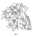
- the mechanism 20 illustrated in Figures 2-4 forms a disc brake which is automatically applied when the transmission is in geared neutral and released at other times.
- the brake mechanism 20 has been developed for use in a constructionally simple agricultural vehicle, specifically a "ride-on" lawnmower.
- this vehicle the left and right hand wheels are driven from a common engine through respective transmissions whose speed ratios (i.e. the ratio of engine speed to wheel speed) are independently and continuously variable.
- speed ratios i.e. the ratio of engine speed to wheel speed
- Such a vehicle may be steered merely by adjustment of the transmissions' ratios, and may be highly manoeuvrable. For instance by setting the transmissions to cause the vehicle wheels to rotate in opposite directions at equal speeds the vehicle can be caused to spin on the spot, an operation referred to as a "zero turn".
- Both of the vehicle's transmissions incorporate, in accordance with the present invention, a brake mechanism 20, which is to be mounted adjacent to a driven vehicle wheel (not shown) and incorporates a wheel shaft 22 which carries the vehicle wheel and is the final output of the transmission.
- the brake mechanism is mounted on a main housing 24, seen in Figure 6 to have at its front a mounting surface 26 to which a continuously variable transmission unit is to be secured with its output shaft protruding through an opening 28 in the housing wall to engage with a first gear 30 rotatably mounted within the main housing 24.
- the transmission unit is not shown in Figures 2 to 6 but Figures 7 and 8 show the main housing 24 mounted on the transmission unit 70 in this manner.
- main housing 24 Concealed within main housing 24 are a second, idler, gear (not seen) which meshes with the first gear 30, and a third, output, gear (not seen) which meshes with the idler gear and drives the wheel shaft 22.
- the first to third gears are of ascending sizes and form a gear train which provides a speed reduction at the wheel shaft 22.
- a brake disc 32 is seen in Figure 2 to have a splined central bore through which it is mounted upon a shaft (omitted from the drawing for clarity) which extends into and rotates along with the idler gear. Braking the disc 32 thus brakes the aforementioned gear train, and hence the wheel shaft 22.
- the brake could in principle act on a different transmission component, but in the particular example illustrated braking the idler gear provides the best compromise, neither rotational speed nor torque being excessive at this point.
- Brake pads are mounted on both sides of the brake disc 32, although both are hidden in the drawings.
- One is carried on a plate 34 secured to the main housing 24.
- the other is carried by an "L" shaped block 36 forming part of a brake lever 38, moving which causes the brake to be applied and released.
- the brake lever 38 further comprises an arm 40 secured to the block 36 e.g. by welding. It has a fulcrum formed by a pin 42 received by the "L" shaped block 36.
- the arm 40 is elbowed at 44 to pass through a clearance opening in a fixed pivot plate 46 secured to the main housing 24, and terminates in an upstanding end plate 48 which mounts a pivot pin 50.
- the pivot pin 50 extends through a bore in the pivot plate 46 and is rendered captive by a nut 52 on the opposite side of the pivot plate 46 from the end plate 48.
- the spring 56 is pre-stressed in compression between the pivot plate 46 and the control lever 54, and its force can be transferred through the control lever to the end plate 48 to apply the brake. However the spring force can be selectively relieved, to release the brake, as will now be explained.
- the control lever 54 cooperates with a cam pin 58 mounted in and radially protruding from the pivot pin 50 to form a cam mechanism controlling the brake lever 38.
- Its sleeve part 53 has a cam surface 59 (see Figures 3 and 4 in particular), formed in this embodiment within a slot 60, which runs upon the cam pin 58 and is biased against it by the action of the spring 56.
- the surface 59 may for example be formed with a detente 62, as in Figure 3 , or with a "V" shape, as in Figure 4 .
- the profile of the cam surface 59 is chosen to provide a desired brake characteristic.
- the profile of Figure 3 for example, gives a relatively abrupt application of the brake at geared neutral.
- the "V" profile at Figure 4 gives more progressive brake application and release.
- An adjuster 68 is threadedly received in the L shaped block 36 and acts on its adjacent brake pad, enabling the pad to be advanced e.g. to accommodate wear.
- the brake mechanism 20 is controlled by a mechanical arrangement in coordination with the vehicle's transmission.
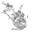
- the control arrangement will now be described with reference to Figures 7 to 9 .
- This arrangement has been developed for use in the agricultural vehicle mentioned above, although it must be understood that the invention could be applied in any of a wide range of vehicles.
- This particular vehicle is controlled through right and left driver operable hand levers 76, 76' each rotatable through a limited range about respective pivots 78, 78'.
- the driver controls the drive ratio provided by right and left continuously variable transmission units 70, 70'. Movement of either hand lever 76, 76' is transmitted through a respective first push rod 80, 80' to a respective crank 82, 82' rotatably mounted in a respective bearing block 84, 84'.
- Cranks 82, 82' are each coupled to a respective transmission push rod 86, 86' which in its turn is coupled to the corresponding transmission unit 70, 70' to control its ratio.
- each of the aforementioned control levers 54, 54' of the brake mechanisms 20, 20' is coupled to a respective brake push rod 88, 88', and each push rod is coupled to the corresponding crank 82, 82' to be moved as the crank turns.
- Push rod lengths are chosen such that the brake is applied when the corresponding hand lever 76, 76' is in the geared neutral position.
- release of the brake as the transmission is moved away from geared neutral may be gradual, so that the brake would be applied over a limited range of hand lever positions on either side of geared neutral.
- the brake mechanism can be adapted to additionally provide a user operable "parking brake” function. That is, a separate user operable control can be provided to apply the brake regardless of transmission ratio.
- this control is formed as a brake lever 100 carried on a rotatably mounted brake bar 102 which further carries actuating levers 104, 104' coupled to respective park brake push rods 106, 106'.
- park brake push rod 106 is seen to be coupled to one limb of an "T" planform lever 108 pivotally mounted on the brake's main housing 24, its other limb being coupled to a pull rod 110 which passes through the brake lever 38 and acts upon it through a helical spring 112 retained on the pull rod by its enlarged head 114.
- the brake lever 38 differs from the one depicted in Figure 2 in that it has been extended upwardly to meet the pull rod.
- To apply the parking brake the driver raises brake lever 100, causing pull rods 110 of both brake mechanisms to move to apply both brakes.
- the transmission units 70, 70' may take any of a number of different forms. They may for example be of "expanding pulley" type. However the preferred type of transmission unit uses a variator of toroidal race, rolling traction type, having a movable control member such as a lever whose position determines the variator's ratio. A suitable unit is described in GB 2423122 and in WO 2006084905 , and the attention of the reader is directed thereto for information on the construction of such a variator.
- the invention is however applicable particularly to transmissions whose variator is of "ratio control" type. That is to say that the ratio adopted by the variator is directly determined by its control system.
- Certain variators are instead “torque controlled” - they receive an input indicative of the torque to be reacted through the variator casing, and changes in ratio take place automatically as a result of the action of the resultant torque on system inertias.
Landscapes
- Engineering & Computer Science (AREA)
- Mechanical Engineering (AREA)
- Transportation (AREA)
- General Engineering & Computer Science (AREA)
- Chemical & Material Sciences (AREA)
- Combustion & Propulsion (AREA)
- Automation & Control Theory (AREA)
- Friction Gearing (AREA)
- Control Of Transmission Device (AREA)
Claims (15)
- Getriebe für ein Radfahrzeug, wobei das Getriebe einen Rotationseingang (14), der von einer Rotationskraftquelle angetrieben werden kann, einen Rotationsausgang (16), der ein Fahrzeugrad (22) antreiben kann, und eine zwischen den Rotationseingang und den Rotationsausgang geschaltete Getriebeeinheit (20) hat, um Antriebskraft zwischen diesen bei einem Drehzahlverhältnis zu übertragen, welches stufenlos über einen Bereich variabel ist, welcher umfasst: negative Verhältnisse, die für eine Umkehrung der Drehrichtung zwischen dem Rotationseingang und dem Rotationsausgang sorgen; positive Verhältnisse, in welchen der Rotationseingang und der Rotationsausgang in derselben Richtung rotieren; und ein Nulldurchgangs-("Geared Neutral")-Verhältnis, in welchem der Rotationsausgang steht; wobei das Getriebe dadurch gekennzeichnet ist, dass es ferner eine Bremse (32) zum Bremsen des Rotationsausgangs und eine Steueranordnung (59, 60) aufweist, die dafür angepasst ist, die Bremse zu betätigen, wenn das Drehzahlverhältnis auf das Nulldurchgangsverhältnis eingestellt ist, und die Bremse zu lösen, sobald das Drehzahlverhältnis von dem Nulldurchgangsverhältnis weg eingestellt ist.
- Getriebe nach Anspruch 1, welches ferner ein vom Benutzer betätigbares Steuerteil (86) aufweist, welches mechanisch mit der Getriebeeinheit dergestalt verbunden ist, dass die Position des Steuerteils das Drehzahlverhältnis vorgibt.
- Getriebe nach Anspruch 2, in welchem das von Benutzer betätigbare Steuerteil (88) mechanisch mit der Bremse dergestalt verbunden ist, dass es, wenn es so positioniert ist, dass die Getriebeeinheit auf Nulldurchgang gestellt ist, auch ein Betätigen der Bremse bewirkt.
- Getriebe nach Anspruch 2 oder Anspruch 3, in welchem die Bremse einen Nockenmechanismus (59, 60) aufweist, der mit dem Steuerteil verbunden ist, um die Bremse zu betätigen und zu lösen.
- Getriebe nach Anspruch 4, in welchem der Nockenmechanismus einen Nockenabschnitt aufweist, welcher eine Nockenoberfläche (62) hat, die so profiliert ist, dass sie eine vorbestimmte Veränderung der Bremskraft mit dem Drehzahlverhältnis bereitstellt.
- Getriebe nach einem der Ansprüche 2 bis 5, das eine vorgespannte Feder (56) aufweist, die dafür eingerichtet ist, eine Kraft zum Betätigen der Bremse auszuüben, und einen Mechanismus (88), der mit der vom Benutzer betätigbaren Steuerung verbunden ist, um selektiv die Federkraft zum Lösen der Bremse zu entspannen.
- Getriebe nach Anspruch 6, mit einem Bremshebel (44), welcher einen Hebeldrehpunkt (42) hat, und dafür eingerichtet ist, auf einen Bremsbelag (36) einzuwirken und durch die vorgespannte Feder betätigt zu werden, wobei der Bremsbelag näher an dem Hebeldrehpunkt als die Feder (56) liegt.
- Getriebe nach einem der vorstehenden Ansprüche, in welchem die Bremse eine Scheibenbremse (32) ist.
- Getriebe nach Anspruch 8, welches ferner Drehzahlreduzierungszahnräder (R3) zwischen der Getriebeeinheit und dem Rotationsausgang (32) aufweist, wobei die Bremse dafür eingerichtet ist, auf eine Scheibe (32) einzuwirken, welche zusammen mit einem der Drehzahlreduzierungszahnräder rotiert.
- Getriebe nach einem der vorstehenden Ansprüche, in welcher die vom Benutzer betätigbare Steuerung ein Hebel (100) ist, der mit der Getriebeeinheit über wenigstens eine Schiebestange (86) verbunden ist.
- Getriebe nach Anspruch 10, in welchem die vom Benutzer betätigbare Steuerung (100) mit der Bremse über wenigstens eine Schiebestange (88) verbunden ist.
- Getriebe nach Anspruch 10 oder Anspruch 11, in welchem die vom Benutzer betätigbare Steuerung (100) mit der ersten Schiebestange (80) verbunden ist, welche wiederum mit einer Kurbel (82) verbunden ist, wobei die Kurbel mit der Getriebeeinheit über eine Getriebeschiebestange (86) verbunden ist.
- Getriebe nach Anspruch 12, in welchem die Bremse (32) mit der Kurbel über eine Kurbelschiebestange (88) verbunden ist.
- Getriebe nach einem der vorstehenden Ansprüche, das ferner einen vom Benutzer betätigbaren Parkbremsensteuerabschnitt (76) aufweist, der zwischen einer Parkbremsenlöseposition, in welcher er den Bremsbetrieb nicht beeinflusst und einer Parkbremsenbetätigungsposition, in welcher er ein Betätigen der Bremse (32) bewirkt, unabhängig davon bewegt werden kann, ob sich das Drehzahlverhältnis bei dem Nulldurchgang befindet.
- Getriebeanordnung mit zwei Getriebeanordnungen (20, 20') gemäß einem der vorstehenden Ansprüche, deren Drehzahlverhältnisse und Bremsen unabhängig steuerbar sind (54, 54'), und deren Rotationsausgänge zur Verbindung mit Rädern auf gegenüberliegenden Seiten eines Fahrzeugs gedacht sind.
Applications Claiming Priority (2)
| Application Number | Priority Date | Filing Date | Title |
|---|---|---|---|
| GB0800826A GB2456543A (en) | 2008-01-17 | 2008-01-17 | CVT with brake. |
| PCT/US2009/031275 WO2009091993A2 (en) | 2008-01-17 | 2009-01-16 | Continuously variable transmission with brake |
Publications (3)
| Publication Number | Publication Date |
|---|---|
| EP2244904A2 EP2244904A2 (de) | 2010-11-03 |
| EP2244904A4 EP2244904A4 (de) | 2012-03-28 |
| EP2244904B1 true EP2244904B1 (de) | 2013-05-29 |
Family
ID=39165902
Family Applications (1)
| Application Number | Title | Priority Date | Filing Date |
|---|---|---|---|
| EP09701499.7A Active EP2244904B1 (de) | 2008-01-17 | 2009-01-16 | Stufenloses getriebe mit bremse |
Country Status (5)
| Country | Link |
|---|---|
| US (1) | US8950562B2 (de) |
| EP (1) | EP2244904B1 (de) |
| ES (1) | ES2425882T3 (de) |
| GB (1) | GB2456543A (de) |
| WO (1) | WO2009091993A2 (de) |
Families Citing this family (2)
| Publication number | Priority date | Publication date | Assignee | Title |
|---|---|---|---|---|
| CN103625454B (zh) * | 2013-12-12 | 2015-09-23 | 中国嘉陵工业股份有限公司(集团) | 一种无人驾驶车辆制动装置 |
| US20160186857A1 (en) * | 2016-03-10 | 2016-06-30 | Caterpillar Inc. | Method of controlling machines with continuously variable transmission |
Family Cites Families (12)
| Publication number | Priority date | Publication date | Assignee | Title |
|---|---|---|---|---|
| CH367396A (de) | 1957-08-29 | 1963-02-15 | Heinrich Dr Ing Ebert | Stufenlos verstellbares Flüssigkeitsgetriebe, insbesondere für schwere Fahrzeuge |
| GB1238121A (de) | 1968-10-01 | 1971-07-07 | ||
| US4600075A (en) * | 1985-02-11 | 1986-07-15 | Gilson Brothers Company | Transmission neutral return for lawn and garden vehicles |
| JP3600286B2 (ja) | 1994-12-02 | 2004-12-15 | 株式会社 神崎高級工機製作所 | 車両用トランスミッション |
| US5809755A (en) | 1994-12-16 | 1998-09-22 | Wright Manufacturing, Inc. | Power mower with riding platform for supporting standing operator |
| US5984431A (en) | 1996-12-31 | 1999-11-16 | Kelsey Hayes Company | Pumpless anti-lock braking system using six solenoid actuated valves |
| JP3464909B2 (ja) * | 1998-04-07 | 2003-11-10 | バンドー化学株式会社 | 変速機のニュートラル保持装置 |
| US6666793B2 (en) * | 2001-02-22 | 2003-12-23 | Nissan Motor Co., Ltd. | Control of infinitely variable transmission |
| ITBO20020443A1 (it) | 2002-07-05 | 2004-01-05 | Cnh Italia | Trasmissione cvt per autoveicoli , in particolare per trattori agricoli |
| US7451865B2 (en) * | 2005-01-18 | 2008-11-18 | Commercial Turf Products, Ltd. | Park brake and control lever interlock for ZTR vehicle |
| US7686108B2 (en) * | 2007-02-09 | 2010-03-30 | Great Plains Manufacturing, Inc. | Electrically released parking brake for zero turn radius mower |
| US20090266654A1 (en) * | 2008-04-25 | 2009-10-29 | Ronald Paul Holland | Elastomeric stabilizers for brake caliper assembly on utility vehicle |
-
2008
- 2008-01-17 GB GB0800826A patent/GB2456543A/en active Pending
-
2009
- 2009-01-16 US US12/863,427 patent/US8950562B2/en active Active
- 2009-01-16 ES ES09701499T patent/ES2425882T3/es active Active
- 2009-01-16 WO PCT/US2009/031275 patent/WO2009091993A2/en active Application Filing
- 2009-01-16 EP EP09701499.7A patent/EP2244904B1/de active Active
Also Published As
| Publication number | Publication date |
|---|---|
| US20110167942A1 (en) | 2011-07-14 |
| EP2244904A4 (de) | 2012-03-28 |
| EP2244904A2 (de) | 2010-11-03 |
| ES2425882T3 (es) | 2013-10-17 |
| WO2009091993A2 (en) | 2009-07-23 |
| US8950562B2 (en) | 2015-02-10 |
| GB2456543A (en) | 2009-07-22 |
| WO2009091993A3 (en) | 2009-10-08 |
| GB0800826D0 (en) | 2008-02-27 |
Similar Documents
| Publication | Publication Date | Title |
|---|---|---|
| US10323732B2 (en) | Continuously variable transmission | |
| US8087482B2 (en) | Wheelchair | |
| JP2548224B2 (ja) | ベルト式無段変速装置 | |
| US6637283B2 (en) | Control apparatus for a continuously variable transmission | |
| CN1241251A (zh) | 摩擦传动装置 | |
| US20150353131A1 (en) | Arrangements for Driving and Steering Of Motor Vehicles | |
| WO2005026577A2 (en) | Variable motion control device and method of use | |
| EP2244904B1 (de) | Stufenloses getriebe mit bremse | |
| US5957803A (en) | Clutch and continuously variable transmission | |
| US4192200A (en) | Variable ratio gear transmission | |
| US20080132376A1 (en) | Power transmission device | |
| JP2548258B2 (ja) | ベルト式無段変速装置 | |
| JPH03204443A (ja) | 無段変速機の制御方式 | |
| JP4035564B2 (ja) | 自動無段連続変速装置 | |
| JP2521298B2 (ja) | 無段変速機 | |
| KR100302770B1 (ko) | 무단변속기 | |
| JP2796968B2 (ja) | 変速機 | |
| KR200425278Y1 (ko) | 무단 변속기 | |
| JP3043948B2 (ja) | 作業車両の操向装置 | |
| CN1111328A (zh) | 自动无级变速器 | |
| JPS6253286A (ja) | 車両の制御装置 | |
| JP2003527548A (ja) | 変速ユニット | |
| US20080026899A1 (en) | Drive train for a tractor | |
| JPH07109235B2 (ja) | コンバインの走行無段変速装置 | |
| JP2001219829A (ja) | 車両の制動装置 |
Legal Events
| Date | Code | Title | Description |
|---|---|---|---|
| PUAI | Public reference made under article 153(3) epc to a published international application that has entered the european phase |
Free format text: ORIGINAL CODE: 0009012 |
|
| 17P | Request for examination filed |
Effective date: 20100813 |
|
| AK | Designated contracting states |
Kind code of ref document: A2 Designated state(s): AT BE BG CH CY CZ DE DK EE ES FI FR GB GR HR HU IE IS IT LI LT LU LV MC MK MT NL NO PL PT RO SE SI SK TR |
|
| AX | Request for extension of the european patent |
Extension state: AL BA RS |
|
| DAX | Request for extension of the european patent (deleted) | ||
| A4 | Supplementary search report drawn up and despatched |
Effective date: 20120227 |
|
| RIC1 | Information provided on ipc code assigned before grant |
Ipc: B60T 7/12 20060101ALI20120221BHEP Ipc: B60T 1/00 20060101ALI20120221BHEP Ipc: B60K 17/00 20060101ALI20120221BHEP Ipc: F16H 37/08 20060101ALI20120221BHEP Ipc: F16H 57/02 20120101ALI20120221BHEP Ipc: B60K 17/04 20060101AFI20120221BHEP Ipc: B60W 10/10 20120101ALI20120221BHEP Ipc: B60W 30/18 20120101ALI20120221BHEP Ipc: F16H 63/30 20060101ALI20120221BHEP Ipc: B60W 10/18 20120101ALI20120221BHEP Ipc: B60T 8/00 20060101ALI20120221BHEP |
|
| RAP1 | Party data changed (applicant data changed or rights of an application transferred) |
Owner name: TOROTRAK (DEVELOPMENT) LIMITED |
|
| GRAP | Despatch of communication of intention to grant a patent |
Free format text: ORIGINAL CODE: EPIDOSNIGR1 |
|
| GRAS | Grant fee paid |
Free format text: ORIGINAL CODE: EPIDOSNIGR3 |
|
| GRAA | (expected) grant |
Free format text: ORIGINAL CODE: 0009210 |
|
| AK | Designated contracting states |
Kind code of ref document: B1 Designated state(s): AT BE BG CH CY CZ DE DK EE ES FI FR GB GR HR HU IE IS IT LI LT LU LV MC MK MT NL NO PL PT RO SE SI SK TR |
|
| REG | Reference to a national code |
Ref country code: GB Ref legal event code: FG4D |
|
| REG | Reference to a national code |
Ref country code: CH Ref legal event code: EP |
|
| REG | Reference to a national code |
Ref country code: AT Ref legal event code: REF Ref document number: 614157 Country of ref document: AT Kind code of ref document: T Effective date: 20130615 |
|
| REG | Reference to a national code |
Ref country code: IE Ref legal event code: FG4D |
|
| REG | Reference to a national code |
Ref country code: DE Ref legal event code: R096 Ref document number: 602009015990 Country of ref document: DE Effective date: 20130725 |
|
| REG | Reference to a national code |
Ref country code: SE Ref legal event code: TRGR |
|
| REG | Reference to a national code |
Ref country code: AT Ref legal event code: MK05 Ref document number: 614157 Country of ref document: AT Kind code of ref document: T Effective date: 20130529 |
|
| REG | Reference to a national code |
Ref country code: ES Ref legal event code: FG2A Ref document number: 2425882 Country of ref document: ES Kind code of ref document: T3 Effective date: 20131017 |
|
| REG | Reference to a national code |
Ref country code: LT Ref legal event code: MG4D |
|
| PG25 | Lapsed in a contracting state [announced via postgrant information from national office to epo] |
Ref country code: AT Free format text: LAPSE BECAUSE OF FAILURE TO SUBMIT A TRANSLATION OF THE DESCRIPTION OR TO PAY THE FEE WITHIN THE PRESCRIBED TIME-LIMIT Effective date: 20130529 Ref country code: IS Free format text: LAPSE BECAUSE OF FAILURE TO SUBMIT A TRANSLATION OF THE DESCRIPTION OR TO PAY THE FEE WITHIN THE PRESCRIBED TIME-LIMIT Effective date: 20130929 Ref country code: NO Free format text: LAPSE BECAUSE OF FAILURE TO SUBMIT A TRANSLATION OF THE DESCRIPTION OR TO PAY THE FEE WITHIN THE PRESCRIBED TIME-LIMIT Effective date: 20130829 Ref country code: GR Free format text: LAPSE BECAUSE OF FAILURE TO SUBMIT A TRANSLATION OF THE DESCRIPTION OR TO PAY THE FEE WITHIN THE PRESCRIBED TIME-LIMIT Effective date: 20130830 Ref country code: PT Free format text: LAPSE BECAUSE OF FAILURE TO SUBMIT A TRANSLATION OF THE DESCRIPTION OR TO PAY THE FEE WITHIN THE PRESCRIBED TIME-LIMIT Effective date: 20130930 Ref country code: LT Free format text: LAPSE BECAUSE OF FAILURE TO SUBMIT A TRANSLATION OF THE DESCRIPTION OR TO PAY THE FEE WITHIN THE PRESCRIBED TIME-LIMIT Effective date: 20130529 Ref country code: FI Free format text: LAPSE BECAUSE OF FAILURE TO SUBMIT A TRANSLATION OF THE DESCRIPTION OR TO PAY THE FEE WITHIN THE PRESCRIBED TIME-LIMIT Effective date: 20130529 Ref country code: SI Free format text: LAPSE BECAUSE OF FAILURE TO SUBMIT A TRANSLATION OF THE DESCRIPTION OR TO PAY THE FEE WITHIN THE PRESCRIBED TIME-LIMIT Effective date: 20130529 |
|
| REG | Reference to a national code |
Ref country code: NL Ref legal event code: VDEP Effective date: 20130529 |
|
| PG25 | Lapsed in a contracting state [announced via postgrant information from national office to epo] |
Ref country code: HR Free format text: LAPSE BECAUSE OF FAILURE TO SUBMIT A TRANSLATION OF THE DESCRIPTION OR TO PAY THE FEE WITHIN THE PRESCRIBED TIME-LIMIT Effective date: 20130529 Ref country code: PL Free format text: LAPSE BECAUSE OF FAILURE TO SUBMIT A TRANSLATION OF THE DESCRIPTION OR TO PAY THE FEE WITHIN THE PRESCRIBED TIME-LIMIT Effective date: 20130529 Ref country code: BG Free format text: LAPSE BECAUSE OF FAILURE TO SUBMIT A TRANSLATION OF THE DESCRIPTION OR TO PAY THE FEE WITHIN THE PRESCRIBED TIME-LIMIT Effective date: 20130829 |
|
| PG25 | Lapsed in a contracting state [announced via postgrant information from national office to epo] |
Ref country code: LV Free format text: LAPSE BECAUSE OF FAILURE TO SUBMIT A TRANSLATION OF THE DESCRIPTION OR TO PAY THE FEE WITHIN THE PRESCRIBED TIME-LIMIT Effective date: 20130529 |
|
| PG25 | Lapsed in a contracting state [announced via postgrant information from national office to epo] |
Ref country code: BE Free format text: LAPSE BECAUSE OF FAILURE TO SUBMIT A TRANSLATION OF THE DESCRIPTION OR TO PAY THE FEE WITHIN THE PRESCRIBED TIME-LIMIT Effective date: 20130529 Ref country code: EE Free format text: LAPSE BECAUSE OF FAILURE TO SUBMIT A TRANSLATION OF THE DESCRIPTION OR TO PAY THE FEE WITHIN THE PRESCRIBED TIME-LIMIT Effective date: 20130529 Ref country code: DK Free format text: LAPSE BECAUSE OF FAILURE TO SUBMIT A TRANSLATION OF THE DESCRIPTION OR TO PAY THE FEE WITHIN THE PRESCRIBED TIME-LIMIT Effective date: 20130529 Ref country code: CZ Free format text: LAPSE BECAUSE OF FAILURE TO SUBMIT A TRANSLATION OF THE DESCRIPTION OR TO PAY THE FEE WITHIN THE PRESCRIBED TIME-LIMIT Effective date: 20130529 Ref country code: SK Free format text: LAPSE BECAUSE OF FAILURE TO SUBMIT A TRANSLATION OF THE DESCRIPTION OR TO PAY THE FEE WITHIN THE PRESCRIBED TIME-LIMIT Effective date: 20130529 |
|
| PG25 | Lapsed in a contracting state [announced via postgrant information from national office to epo] |
Ref country code: RO Free format text: LAPSE BECAUSE OF FAILURE TO SUBMIT A TRANSLATION OF THE DESCRIPTION OR TO PAY THE FEE WITHIN THE PRESCRIBED TIME-LIMIT Effective date: 20130529 Ref country code: NL Free format text: LAPSE BECAUSE OF FAILURE TO SUBMIT A TRANSLATION OF THE DESCRIPTION OR TO PAY THE FEE WITHIN THE PRESCRIBED TIME-LIMIT Effective date: 20130529 |
|
| PLBE | No opposition filed within time limit |
Free format text: ORIGINAL CODE: 0009261 |
|
| STAA | Information on the status of an ep patent application or granted ep patent |
Free format text: STATUS: NO OPPOSITION FILED WITHIN TIME LIMIT |
|
| 26N | No opposition filed |
Effective date: 20140303 |
|
| REG | Reference to a national code |
Ref country code: DE Ref legal event code: R097 Ref document number: 602009015990 Country of ref document: DE Effective date: 20140303 |
|
| PG25 | Lapsed in a contracting state [announced via postgrant information from national office to epo] |
Ref country code: LU Free format text: LAPSE BECAUSE OF FAILURE TO SUBMIT A TRANSLATION OF THE DESCRIPTION OR TO PAY THE FEE WITHIN THE PRESCRIBED TIME-LIMIT Effective date: 20140116 Ref country code: MC Free format text: LAPSE BECAUSE OF FAILURE TO SUBMIT A TRANSLATION OF THE DESCRIPTION OR TO PAY THE FEE WITHIN THE PRESCRIBED TIME-LIMIT Effective date: 20130529 |
|
| REG | Reference to a national code |
Ref country code: CH Ref legal event code: PL |
|
| PG25 | Lapsed in a contracting state [announced via postgrant information from national office to epo] |
Ref country code: CH Free format text: LAPSE BECAUSE OF NON-PAYMENT OF DUE FEES Effective date: 20140131 Ref country code: LI Free format text: LAPSE BECAUSE OF NON-PAYMENT OF DUE FEES Effective date: 20140131 |
|
| REG | Reference to a national code |
Ref country code: IE Ref legal event code: MM4A |
|
| PG25 | Lapsed in a contracting state [announced via postgrant information from national office to epo] |
Ref country code: IE Free format text: LAPSE BECAUSE OF NON-PAYMENT OF DUE FEES Effective date: 20140116 |
|
| REG | Reference to a national code |
Ref country code: FR Ref legal event code: PLFP Year of fee payment: 7 |
|
| PGFP | Annual fee paid to national office [announced via postgrant information from national office to epo] |
Ref country code: TR Payment date: 20150513 Year of fee payment: 7 Ref country code: SE Payment date: 20150520 Year of fee payment: 7 |
|
| REG | Reference to a national code |
Ref country code: FR Ref legal event code: PLFP Year of fee payment: 8 |
|
| PG25 | Lapsed in a contracting state [announced via postgrant information from national office to epo] |
Ref country code: MT Free format text: LAPSE BECAUSE OF FAILURE TO SUBMIT A TRANSLATION OF THE DESCRIPTION OR TO PAY THE FEE WITHIN THE PRESCRIBED TIME-LIMIT Effective date: 20130529 |
|
| PG25 | Lapsed in a contracting state [announced via postgrant information from national office to epo] |
Ref country code: CY Free format text: LAPSE BECAUSE OF FAILURE TO SUBMIT A TRANSLATION OF THE DESCRIPTION OR TO PAY THE FEE WITHIN THE PRESCRIBED TIME-LIMIT Effective date: 20130529 |
|
| PG25 | Lapsed in a contracting state [announced via postgrant information from national office to epo] |
Ref country code: HU Free format text: LAPSE BECAUSE OF FAILURE TO SUBMIT A TRANSLATION OF THE DESCRIPTION OR TO PAY THE FEE WITHIN THE PRESCRIBED TIME-LIMIT; INVALID AB INITIO Effective date: 20090116 |
|
| PG25 | Lapsed in a contracting state [announced via postgrant information from national office to epo] |
Ref country code: SE Free format text: LAPSE BECAUSE OF NON-PAYMENT OF DUE FEES Effective date: 20160117 |
|
| REG | Reference to a national code |
Ref country code: FR Ref legal event code: PLFP Year of fee payment: 9 |
|
| REG | Reference to a national code |
Ref country code: FR Ref legal event code: PLFP Year of fee payment: 10 |
|
| REG | Reference to a national code |
Ref country code: ES Ref legal event code: PC2A Owner name: ALLISON TRANSMISSION, INC. Effective date: 20180530 Ref country code: ES Ref legal event code: PC2A Effective date: 20180530 |
|
| PG25 | Lapsed in a contracting state [announced via postgrant information from national office to epo] |
Ref country code: MK Free format text: LAPSE BECAUSE OF FAILURE TO SUBMIT A TRANSLATION OF THE DESCRIPTION OR TO PAY THE FEE WITHIN THE PRESCRIBED TIME-LIMIT Effective date: 20130529 |
|
| REG | Reference to a national code |
Ref country code: FR Ref legal event code: TP Owner name: ALLISON TRANSMISSION, INC., US Effective date: 20181004 |
|
| REG | Reference to a national code |
Ref country code: DE Ref legal event code: R082 Ref document number: 602009015990 Country of ref document: DE Representative=s name: MITSCHERLICH, PATENT- UND RECHTSANWAELTE PARTM, DE Ref country code: DE Ref legal event code: R081 Ref document number: 602009015990 Country of ref document: DE Owner name: ALLISON TRANSMISSION, INC., INDIANAPOLIS, US Free format text: FORMER OWNER: TOROTRAK (DEVELOPMENT) LTD., LEYLAND, LANCASHIRE, GB |
|
| REG | Reference to a national code |
Ref country code: GB Ref legal event code: 732E Free format text: REGISTERED BETWEEN 20190117 AND 20190123 |
|
| PGFP | Annual fee paid to national office [announced via postgrant information from national office to epo] |
Ref country code: FR Payment date: 20230125 Year of fee payment: 15 |
|
| PGFP | Annual fee paid to national office [announced via postgrant information from national office to epo] |
Ref country code: IT Payment date: 20230120 Year of fee payment: 15 |
|
| P01 | Opt-out of the competence of the unified patent court (upc) registered |
Effective date: 20230521 |
|
| PGFP | Annual fee paid to national office [announced via postgrant information from national office to epo] |
Ref country code: ES Payment date: 20240201 Year of fee payment: 16 |
|
| PGFP | Annual fee paid to national office [announced via postgrant information from national office to epo] |
Ref country code: DE Payment date: 20240129 Year of fee payment: 16 Ref country code: GB Payment date: 20240129 Year of fee payment: 16 |