EP2244600B1 - Fingerring mit adaptervorrichtung zur automatischen anpassung der ringgrösse - Google Patents
Fingerring mit adaptervorrichtung zur automatischen anpassung der ringgrösse Download PDFInfo
- Publication number
- EP2244600B1 EP2244600B1 EP09706918A EP09706918A EP2244600B1 EP 2244600 B1 EP2244600 B1 EP 2244600B1 EP 09706918 A EP09706918 A EP 09706918A EP 09706918 A EP09706918 A EP 09706918A EP 2244600 B1 EP2244600 B1 EP 2244600B1
- Authority
- EP
- European Patent Office
- Prior art keywords
- arm
- ring according
- ring
- fixed
- seat
- Prior art date
- Legal status (The legal status is an assumption and is not a legal conclusion. Google has not performed a legal analysis and makes no representation as to the accuracy of the status listed.)
- Active
Links
- 230000000284 resting effect Effects 0.000 claims abstract description 4
- 238000003466 welding Methods 0.000 claims description 8
- 230000007547 defect Effects 0.000 claims description 2
- 239000010437 gem Substances 0.000 description 5
- 229910001751 gemstone Inorganic materials 0.000 description 2
- JHJNPOSPVGRIAN-SFHVURJKSA-N n-[3-[(1s)-1-[[6-(3,4-dimethoxyphenyl)pyrazin-2-yl]amino]ethyl]phenyl]-5-methylpyridine-3-carboxamide Chemical compound C1=C(OC)C(OC)=CC=C1C1=CN=CC(N[C@@H](C)C=2C=C(NC(=O)C=3C=C(C)C=NC=3)C=CC=2)=N1 JHJNPOSPVGRIAN-SFHVURJKSA-N 0.000 description 2
- 230000006978 adaptation Effects 0.000 description 1
- 230000009977 dual effect Effects 0.000 description 1
- 238000004519 manufacturing process Methods 0.000 description 1
Images


Classifications
-
- A—HUMAN NECESSITIES
- A44—HABERDASHERY; JEWELLERY
- A44C—PERSONAL ADORNMENTS, e.g. JEWELLERY; COINS
- A44C9/00—Finger-rings
- A44C9/02—Finger-rings adjustable
Definitions
- the present invention relates to a finger ring provided with an adapter device for automatically adjusting the ring size.
- US patent US6748764 describes a ring comprising a circular structure which defines an internal cavity which accommodates one or more springs. Such springs act against one or more arms hinged to the structure, so as to rotate the arms towards the interior of the ring against the finger on which the ring is worn. In such a manner, the position of the arms with respect to the centre of the ring may be automatically adapted according to the size of the finger on which the ring is worn.
- a ring defining a seat to be worn on a finger and comprising:
- numeral 1 indicates as a whole a ring defining a substantially circular seat 3, in which a finger may be inserted along an axis 6 for wearing the ring 1 on such a finger.
- the ring 1 comprises: an annular structure 2, which is shown in section according to a symmetry plane orthogonal to axis 6; a series of precious stones 5, which are set on the structure 2, in fixed positions along the external periphery of the structure 2 and are angularly spaced about the axis 6; and an adapter device 10 for automatically adjusting the diameter , of the seat 3, i.e. the size of the ring 1, according to the circumference of the finger on which the ring 1 is worn.
- the device 10 comprises five arms 11 arranged along the internal periphery of the structure 2 in order to delimit the seat 3.
- the arms 11 are equally spaced about the axis 6 and coupled to the structure 2 so as to rotate between a retracted position and an forward position with respect to the centre of the seat 3.
- the ends of the arms 11 are defined by bushings 12 coupled to respective hinge pins 13, which are parallel to axis 6 and define the rotation axes of the arms 11.
- the axial ends of the pins 13 protrude from the bushings 12 and engage respective circular through holes (not shown) of the structure 2.
- the arms 11 comprise respective intermediate portions 15, which extend in a substantially circumferential direction and have a U-shaped cross section, considering section planes passing through axis 6, so as to define respective compartments 16, on the rear side radially facing the structure 2.
- the portions 15 On the opposite side, i.e. towards the centre of the seat 3, the portions 15 have respective arched surfaces 17 which, in use, are in contact with the finger on which the ring 1 is fitted.
- each arm 11 comprises a corresponding tooth 18, which protrudes from the portion 15, both circumferentially in the opposite direction with respect to the bushing 12, and radially outwards.
- the teeth 18 are arranged resting against respective shoulders 19 of the structure 2 to define the stroke stop for adjusting the arms 11.
- the shoulders 19 are interposed between the arms 11 in the circumferential direction and define five windows 21 which are engaged by the arms 11, respectively.
- the device 10 For each arm 11, the device 10 comprises a corresponding pair of wire springs 22.
- the wire springs 22 of each pair are radially interposed between the structure 2 and the arm 11 to push the arm 11 to the forward position, are elongated in the circumferential direction, and are parallel and spaced from one another.
- the two wire springs 22 comprise respective substantially rectilinear portions 23, which are tangential to the arm 11, accommodated in the compartment 16, and fixed to the arm 11. Specifically, the ends of the portions 23 are fixed to the bushing 12 by means of welding zones 25 obtained by means of laser.
- the portions 23 engage respective passages 26 defined by the bottom surface of the compartment 16 and corresponding semi-cylindrical portions 27, which are fixed to the bottom surface of the compartment 16.
- the portions 23 have a diameter which approximates by defect the size of the passages 26, and therefore may be easily inserted into the portions .27 during the step of assembling.
- the two wire springs 22 comprise respective arched portions 28, which extends outside the compartment 16, have a concavity facing towards the arm 11, and rest against the structure 2.
- the end tips of the portions 28 are radially spaced from arm 11 and structure 2 when the arm 11 is in the forward position towards the centre of the seat 3.
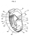
- FIG. 2 shows a ring 1a, in which the components are indicated by the same reference numbers used in figure 1 and are followed by the reference letter "a".
- the precious stones 5a are arranged only on one side of the structure 2a, and not along the entire periphery.
- the structure 2a defines an internal channel 40a, which accommodates the springs 22a and communicates with the seat 3a through the windows 21a.
- the windows 21a as well as the arms 11a are two, and diametrically opposite to each other.
- the hinge pins 13a are arranged in a zone which is diametrically opposite to the precious stone 5a, whereby the arms 11a secure the finger without pushing it towards the precious stone 5a when the ring 1 is worn.
- each arm 11a there are six wire springs 22a for each arm 11a.
- the ends of the portions 23a are arranged in the compartment 16a and are fixed through the welding zones 25a to the end of the portion 15a which is opposite, in the circumferential direction, to the bushing 12a, whereby the portions 28a are facing towards the bushings 12a.
- FIG. 3 shows a ring 1b, in which the components are indicated by the same reference numbers used in figures 1 and 2 and followed by the reference letter "b".
- the structure 2b is free from precious stones, defines an internal circular channel 40b and has an external shape similar to that of a wedding ring.
- the windows 21b as well as the arms 11b (only one of which is shown) are three and arranged at 120°.
- the wire springs are replaced with a flat spring 22b with a profile having a similar shape to that of the wire springs described above, when seen in the axial direction.
- the semi-cylindrical portions 27,27a are replaced with plate portions 27b parallel to the bottom surface of the compartments 16b so as to define rectangular section passages 26b.
- the type of springs used i.e. springs having a shape elongated in the circumferential direction, allows to achieve a compact structure in the radial direction. Furthermore, fixing one end of the springs 22 to either the arm 11 or the structure 2 allows the springs 22,22a,22b to be arranged in constantly fixed positions, both when assembling the arms 11, 11a, 11b to the structure 2,2a,2b, resulting in increased simplicity and speed for manufacturing the ring 1, and in use, resulting in an increased reliability of the device 10,10a,10b.
- the device 10,10a,10b is also reliable in virtue of the portions 27,27a,27b transmitting the elastic bias between the springs 22,22a,22b and the arm 11, 11a, 11b and avoid such an elastic bias from being directly released onto the welding zones 25,25a,25b.
- the portions 28,28a,28b have a concave shape which allows the springs 22,22a,22b to smoothly slide on the structure 2,2a,2b during the movement of the arms 11, 11a, 11b between the forward and retracted positions.
- the mode for fastening the springs 22,22a,22b could be different from welding (e.g. portions 23,23a,23b could be secured into the passages 26,26a,26b by crushing the portions 27,27a,27b); and/or the number of arms 11, 11a, 11b, could be different from that indicated by way of example.
- the number of wire springs 22,22a or flat springs 22b could be different from that shown in the appended figures; and/or one end could be fixed to the structure instead of to the arms, in a dual manner with respect to that shown above by way of example.
Landscapes
- Adornments (AREA)
Claims (11)
- Ring (1), der einen Sitz bzw. eine Auflage (3) definiert, um auf einem Finger getragen zu werden, und umfasst:- eine Struktur (2); und- eine Adapter bzw. Anpassungsvorrichtung (10) zum automatischen Einstellen des Durchmessers der Auflage (3), wobei die Anpassungsvorrichtung umfasst:dadurch gekennzeichnet, dass das längliche elastische Element (22) ein Profil hat, das sich im Wesentlichen in einer Umfangsrichtung erstreckt und umfasst:a) wenigstens einen Arm (11), der mit der Struktur (2) verbunden ist, um sich zwischen einer zurückgezogenen Position und einer Vorwärtsposition in Bezug auf die Mitte der Auflage (3) zu drehen, undb) elastische Mittel (22), die radial zwischen der Struktur (2) und dem Arm (11) eingefügt sind, um den Arm (11) in die Vorwärtsposition zu drücken; wobei die elastischen Mittel wenigstens ein längliches elastisches Element (22) umfassen;- einen ersten Endabschnitt (23) mit einem Ende, das durch eine Schweißzone (25) an der Struktur (2) oder dem Arm (11) befestigt ist, und- einen zweiten Endabschnitt (28), der entgegengesetzt zu dem ersten Endabschnitt (23) entlang der Umfangsrichtung und gegen die/den andere/n der Struktur und des Arms ruhend bzw. aufliegend angeordnet ist.
- Ring nach Anspruch 1, dadurch gekennzeichnet, dass das Ende mit Hilfe einer Laserschweißung fixiert ist.
- Ring nach Anspruch 1 oder 2, dadurch gekennzeichnet, dass das Ende an dem Arm (11) fixiert ist.
- Ring nach Anspruch 3, dadurch gekennzeichnet, dass der erste Endabschnitt durch einen im Wesentlichen geradlinigen Abschnitt (23) tangential zu dem Arm (11) definiert ist und in einen Durchgang (26) eingreift, der in Bezug auf den Arm (11) fixiert ist.
- Ring nach Anspruch 4, dadurch gekennzeichnet, dass die Größe des im Wesentlichen geradlinigen Abschnitts (23) die Größe des Durchgangs (26) durch eine fehlende Größe bzw. Störstelle annähert, um das Ende während der Montage in den Durchgang (26) einzusetzen.
- Ring nach Anspruch 5, dadurch gekennzeichnet, dass der Durchgang (26) durch eine hintere Fläche des Arms (11) und einen halbzylindrischen Abschnitt (27), der an der hinteren Oberfläche fixiert ist, definiert ist.
- Ring nach einem der Ansprüche 3 bis 6, dadurch gekennzeichnet, dass der Arm (11) einen U-förmigen Querschnitt hat und eine hintere Kammer (16) definiert, die das Ende unterbringt.
- Ring nach einem der Ansprüche 3 bis 7, dadurch gekennzeichnet, dass das Ende durch die Schweißzone (25) an einer Gelenkbuchse (12) des Arms (11) fixiert ist.
- Ring nach einem der Ansprüche 3 bis 8, dadurch gekennzeichnet, dass der zweite Endabschnitt (28) mit einer Höhlung gewölbt ist, die in Richtung des Arms (11) gewandt ist.
- Ring nach einem der vorhergehenden Ansprüche, dadurch gekennzeichnet, dass die elastischen Mittel eine Vielzahl der parallel und wechselseitig beabstandeten länglichen elastischen Elemente (22) umfassen.
- Ring nach einem der vorhergehenden Ansprüche, dadurch gekennzeichnet, dass die Struktur (2) einen Innenkanal (40) definiert, der die elastischen Mittel (22a) unterbringt und durch eine Öffnung (21 a), in die durch den Arm (11a) eingegriffen wird, mit der Auflage (3a) in Verbindung steht.
Applications Claiming Priority (2)
| Application Number | Priority Date | Filing Date | Title |
|---|---|---|---|
| IT000056A ITTO20080056A1 (it) | 2008-01-28 | 2008-01-28 | Anello da dita provvisto di un dispositivo adattatore per variare automaticamente la misura dell'anello |
| PCT/IB2009/000129 WO2009095761A2 (en) | 2008-01-28 | 2009-01-27 | Finger ring provided with an adapter device for automatically adjusting the ring size |
Publications (2)
| Publication Number | Publication Date |
|---|---|
| EP2244600A2 EP2244600A2 (de) | 2010-11-03 |
| EP2244600B1 true EP2244600B1 (de) | 2012-06-20 |
Family
ID=40290409
Family Applications (1)
| Application Number | Title | Priority Date | Filing Date |
|---|---|---|---|
| EP09706918A Active EP2244600B1 (de) | 2008-01-28 | 2009-01-27 | Fingerring mit adaptervorrichtung zur automatischen anpassung der ringgrösse |
Country Status (5)
| Country | Link |
|---|---|
| US (1) | US8573004B2 (de) |
| EP (1) | EP2244600B1 (de) |
| JP (1) | JP2011510729A (de) |
| IT (1) | ITTO20080056A1 (de) |
| WO (1) | WO2009095761A2 (de) |
Families Citing this family (8)
| Publication number | Priority date | Publication date | Assignee | Title |
|---|---|---|---|---|
| US20120180523A1 (en) * | 2011-01-17 | 2012-07-19 | Meyerhoff John E | Adjustable jewelry shank |
| RU2617381C2 (ru) * | 2012-07-20 | 2017-04-24 | Чинкве С.Р.Л. | Кольцо |
| US8960203B2 (en) * | 2012-08-27 | 2015-02-24 | Sabrina Temple | Hair implement with rotational bearing |
| ITUA20162012A1 (it) | 2016-03-24 | 2017-09-24 | Escobar Andres Mauricio Zuluaga | Anello ornamentale per dita |
| US10390591B2 (en) | 2017-10-27 | 2019-08-27 | Vittorio Bassan | Variable-sized finger ring |
| US10905207B2 (en) | 2018-02-15 | 2021-02-02 | Krainz Creations, Inc. | Jewelry ring having an automatic size adjusting device |
| US12082665B2 (en) | 2020-05-22 | 2024-09-10 | Barry Nisguretsky | Jewelry arrangement system |
| CN218635464U (zh) * | 2022-12-06 | 2023-03-17 | 曾成盛 | 一种环形饰品 |
Family Cites Families (25)
| Publication number | Priority date | Publication date | Assignee | Title |
|---|---|---|---|---|
| US486720A (en) * | 1892-11-22 | Finger-ring | ||
| US389292A (en) * | 1888-09-11 | flohr | ||
| US2582083A (en) * | 1946-12-27 | 1952-01-08 | Robert M Kaufman | Ring |
| US2615314A (en) * | 1952-07-11 | 1952-10-28 | Tru Fit Company | Self-adjusting finger ring |
| US2745265A (en) * | 1952-09-25 | 1956-05-15 | Axel Bros Inc | Detachable ring guard for finger rings |
| US2745266A (en) * | 1953-05-28 | 1956-05-15 | Axel Bros Inc | Ring guard with spring pressed pivoted member |
| US2873586A (en) * | 1953-10-29 | 1959-02-17 | Krandall Sidney | Finger ring having two internal finger gripping means with diverging ends |
| US2778207A (en) * | 1953-12-18 | 1957-01-22 | Fiddelman & Son Inc J | Self-adjusting finger ring having spring biased pivoted members |
| US2787142A (en) * | 1954-01-07 | 1957-04-02 | Axel Bros Inc | Resiliently retained finger ring guard |
| US3237426A (en) * | 1963-04-17 | 1966-03-01 | Jabel Ring Mfg Co | Self-adjusting guard for finger rings |
| US3423956A (en) * | 1967-06-02 | 1969-01-28 | Moe Manne | Expandible ring with means biasing it to contracted position |
| US3483718A (en) * | 1968-07-30 | 1969-12-16 | Albert C Lodrini | Device for narrowing the diameter of a finger ring |
| US4245485A (en) * | 1979-05-31 | 1981-01-20 | Bushong Robert N | Finger ring guard |
| US4471634A (en) * | 1983-01-26 | 1984-09-18 | Sol Kaplan | Plural section ring sizer |
| US4935977A (en) * | 1988-01-27 | 1990-06-26 | Yamada Co., Ltd. | Leaf spring |
| GB8830050D0 (en) * | 1988-12-23 | 1989-02-22 | Creates Allan | Finger ring |
| US5269497A (en) * | 1990-12-17 | 1993-12-14 | Flexsteel Industries, Inc. | Seat spring structure |
| US6003334A (en) * | 1994-07-29 | 1999-12-21 | Miller; Bryan J. | Finger ring size adjusting device and method |
| US5499430A (en) * | 1994-08-10 | 1996-03-19 | Strazar; Andrew A. | Hose clamp with supplemental holding fingers |
| GB2326920A (en) * | 1997-07-01 | 1999-01-06 | Rasmussen Gmbh | Clamp for clamping a hose on a pipe portion |
| US6748764B1 (en) | 2000-09-20 | 2004-06-15 | Thomas Bruce Roemer | Self-adjusting ring size reducer |
| JP3254450B1 (ja) | 2001-06-01 | 2002-02-04 | 株式会社大芝 | 指 輪 |
| CH695205A5 (de) | 2001-10-15 | 2006-01-31 | Guebelin Ag | Ringartiges Schmuckstück mit einer grössenvariablen Aufnahmeöffnung zur Aufnahme einer Extremität einer Person. |
| US7430879B2 (en) * | 2005-01-21 | 2008-10-07 | Hearts On Fire Company | Adjustable size ring |
| US7409836B2 (en) * | 2005-01-21 | 2008-08-12 | Hearts On Fire Company | Adjustable size ring |
-
2008
- 2008-01-28 IT IT000056A patent/ITTO20080056A1/it unknown
-
2009
- 2009-01-27 JP JP2010544805A patent/JP2011510729A/ja active Pending
- 2009-01-27 US US12/865,037 patent/US8573004B2/en not_active Expired - Fee Related
- 2009-01-27 WO PCT/IB2009/000129 patent/WO2009095761A2/en not_active Ceased
- 2009-01-27 EP EP09706918A patent/EP2244600B1/de active Active
Also Published As
| Publication number | Publication date |
|---|---|
| JP2011510729A (ja) | 2011-04-07 |
| WO2009095761A3 (en) | 2009-11-26 |
| US8573004B2 (en) | 2013-11-05 |
| ITTO20080056A1 (it) | 2009-07-29 |
| US20110048073A1 (en) | 2011-03-03 |
| WO2009095761A2 (en) | 2009-08-06 |
| EP2244600A2 (de) | 2010-11-03 |
Similar Documents
| Publication | Publication Date | Title |
|---|---|---|
| EP2244600B1 (de) | Fingerring mit adaptervorrichtung zur automatischen anpassung der ringgrösse | |
| US10251456B2 (en) | Annular piece of jewelry having movable coaxial ring elements | |
| US9188959B2 (en) | Watch case with orientable and indexed bezel | |
| JP5727059B2 (ja) | 耐衝撃性センターホイール | |
| JP6179595B2 (ja) | リング、および、リングの製造方法 | |
| US7293332B2 (en) | Device for fastening an extremity of a link to an object | |
| EA030281B1 (ru) | Ключ и цилиндрический замок с дисковыми кулачками | |
| RU2008132959A (ru) | Подшипник скольжения и рулевой механизм реечного типа для использования в автомобиле | |
| US8979688B2 (en) | Cushioning structure for a sprocket | |
| ITBO20030683A1 (it) | Tamburo centratore per macchine mettifiltro | |
| JP2023161566A (ja) | 軸受ローラを有するケージフリーホイール | |
| CN108697210A (zh) | 一种双重可微调表带长度的表带扣 | |
| US20220079303A1 (en) | Extensible jewelry items | |
| CN107002518A (zh) | 用于凸轮轴相位器中的弹簧导引件的支承销 | |
| KR20210135931A (ko) | 타임피스 인덱싱 요소 | |
| DE602004024425D1 (de) | Herstellungsverfahren für acylindrische optische einrichtungen | |
| EP3793393B1 (de) | Schmuckring mit automatischer grösseneinstellvorrichtung | |
| JP6631070B2 (ja) | 搬送チェーン | |
| EP1859175B1 (de) | Vorrichtung zur stütze einer drehwelle | |
| WO2014136828A1 (ja) | 一方向クラッチ | |
| US9506508B2 (en) | One-way transmission module | |
| JP5795271B2 (ja) | 中空部を有する歯車装置 | |
| JP2026013670A (ja) | 一方向クラッチ | |
| KR20230056634A (ko) | 탈착구조가 형성된 기능성 반지 및 그 제조방법 | |
| JP5477880B2 (ja) | 車両サンバイザ用シャフト |
Legal Events
| Date | Code | Title | Description |
|---|---|---|---|
| PUAI | Public reference made under article 153(3) epc to a published international application that has entered the european phase |
Free format text: ORIGINAL CODE: 0009012 |
|
| 17P | Request for examination filed |
Effective date: 20100820 |
|
| AK | Designated contracting states |
Kind code of ref document: A2 Designated state(s): AT BE BG CH CY CZ DE DK EE ES FI FR GB GR HR HU IE IS IT LI LT LU LV MC MK MT NL NO PL PT RO SE SI SK TR |
|
| AX | Request for extension of the european patent |
Extension state: AL BA RS |
|
| DAX | Request for extension of the european patent (deleted) | ||
| GRAP | Despatch of communication of intention to grant a patent |
Free format text: ORIGINAL CODE: EPIDOSNIGR1 |
|
| GRAS | Grant fee paid |
Free format text: ORIGINAL CODE: EPIDOSNIGR3 |
|
| GRAA | (expected) grant |
Free format text: ORIGINAL CODE: 0009210 |
|
| AK | Designated contracting states |
Kind code of ref document: B1 Designated state(s): AT BE BG CH CY CZ DE DK EE ES FI FR GB GR HR HU IE IS IT LI LT LU LV MC MK MT NL NO PL PT RO SE SI SK TR |
|
| REG | Reference to a national code |
Ref country code: GB Ref legal event code: FG4D |
|
| REG | Reference to a national code |
Ref country code: CH Ref legal event code: EP |
|
| REG | Reference to a national code |
Ref country code: AT Ref legal event code: REF Ref document number: 562519 Country of ref document: AT Kind code of ref document: T Effective date: 20120715 |
|
| REG | Reference to a national code |
Ref country code: IE Ref legal event code: FG4D |
|
| REG | Reference to a national code |
Ref country code: DE Ref legal event code: R096 Ref document number: 602009007713 Country of ref document: DE Effective date: 20120816 |
|
| PG25 | Lapsed in a contracting state [announced via postgrant information from national office to epo] |
Ref country code: NO Free format text: LAPSE BECAUSE OF FAILURE TO SUBMIT A TRANSLATION OF THE DESCRIPTION OR TO PAY THE FEE WITHIN THE PRESCRIBED TIME-LIMIT Effective date: 20120920 Ref country code: FI Free format text: LAPSE BECAUSE OF FAILURE TO SUBMIT A TRANSLATION OF THE DESCRIPTION OR TO PAY THE FEE WITHIN THE PRESCRIBED TIME-LIMIT Effective date: 20120620 Ref country code: SE Free format text: LAPSE BECAUSE OF FAILURE TO SUBMIT A TRANSLATION OF THE DESCRIPTION OR TO PAY THE FEE WITHIN THE PRESCRIBED TIME-LIMIT Effective date: 20120620 Ref country code: LT Free format text: LAPSE BECAUSE OF FAILURE TO SUBMIT A TRANSLATION OF THE DESCRIPTION OR TO PAY THE FEE WITHIN THE PRESCRIBED TIME-LIMIT Effective date: 20120620 |
|
| REG | Reference to a national code |
Ref country code: NL Ref legal event code: VDEP Effective date: 20120620 |
|
| REG | Reference to a national code |
Ref country code: AT Ref legal event code: MK05 Ref document number: 562519 Country of ref document: AT Kind code of ref document: T Effective date: 20120620 |
|
| REG | Reference to a national code |
Ref country code: LT Ref legal event code: MG4D Effective date: 20120620 |
|
| PG25 | Lapsed in a contracting state [announced via postgrant information from national office to epo] |
Ref country code: GR Free format text: LAPSE BECAUSE OF FAILURE TO SUBMIT A TRANSLATION OF THE DESCRIPTION OR TO PAY THE FEE WITHIN THE PRESCRIBED TIME-LIMIT Effective date: 20120921 Ref country code: SI Free format text: LAPSE BECAUSE OF FAILURE TO SUBMIT A TRANSLATION OF THE DESCRIPTION OR TO PAY THE FEE WITHIN THE PRESCRIBED TIME-LIMIT Effective date: 20120620 Ref country code: LV Free format text: LAPSE BECAUSE OF FAILURE TO SUBMIT A TRANSLATION OF THE DESCRIPTION OR TO PAY THE FEE WITHIN THE PRESCRIBED TIME-LIMIT Effective date: 20120620 Ref country code: HR Free format text: LAPSE BECAUSE OF FAILURE TO SUBMIT A TRANSLATION OF THE DESCRIPTION OR TO PAY THE FEE WITHIN THE PRESCRIBED TIME-LIMIT Effective date: 20120620 |
|
| REG | Reference to a national code |
Ref country code: CH Ref legal event code: NV Representative=s name: MOINAS AND SAVOYE SA, CH |
|
| PG25 | Lapsed in a contracting state [announced via postgrant information from national office to epo] |
Ref country code: EE Free format text: LAPSE BECAUSE OF FAILURE TO SUBMIT A TRANSLATION OF THE DESCRIPTION OR TO PAY THE FEE WITHIN THE PRESCRIBED TIME-LIMIT Effective date: 20120620 Ref country code: SK Free format text: LAPSE BECAUSE OF FAILURE TO SUBMIT A TRANSLATION OF THE DESCRIPTION OR TO PAY THE FEE WITHIN THE PRESCRIBED TIME-LIMIT Effective date: 20120620 Ref country code: CZ Free format text: LAPSE BECAUSE OF FAILURE TO SUBMIT A TRANSLATION OF THE DESCRIPTION OR TO PAY THE FEE WITHIN THE PRESCRIBED TIME-LIMIT Effective date: 20120620 Ref country code: AT Free format text: LAPSE BECAUSE OF FAILURE TO SUBMIT A TRANSLATION OF THE DESCRIPTION OR TO PAY THE FEE WITHIN THE PRESCRIBED TIME-LIMIT Effective date: 20120620 Ref country code: BE Free format text: LAPSE BECAUSE OF FAILURE TO SUBMIT A TRANSLATION OF THE DESCRIPTION OR TO PAY THE FEE WITHIN THE PRESCRIBED TIME-LIMIT Effective date: 20120620 Ref country code: CY Free format text: LAPSE BECAUSE OF FAILURE TO SUBMIT A TRANSLATION OF THE DESCRIPTION OR TO PAY THE FEE WITHIN THE PRESCRIBED TIME-LIMIT Effective date: 20120620 Ref country code: IS Free format text: LAPSE BECAUSE OF FAILURE TO SUBMIT A TRANSLATION OF THE DESCRIPTION OR TO PAY THE FEE WITHIN THE PRESCRIBED TIME-LIMIT Effective date: 20121020 Ref country code: RO Free format text: LAPSE BECAUSE OF FAILURE TO SUBMIT A TRANSLATION OF THE DESCRIPTION OR TO PAY THE FEE WITHIN THE PRESCRIBED TIME-LIMIT Effective date: 20120620 |
|
| PG25 | Lapsed in a contracting state [announced via postgrant information from national office to epo] |
Ref country code: PL Free format text: LAPSE BECAUSE OF FAILURE TO SUBMIT A TRANSLATION OF THE DESCRIPTION OR TO PAY THE FEE WITHIN THE PRESCRIBED TIME-LIMIT Effective date: 20120620 Ref country code: PT Free format text: LAPSE BECAUSE OF FAILURE TO SUBMIT A TRANSLATION OF THE DESCRIPTION OR TO PAY THE FEE WITHIN THE PRESCRIBED TIME-LIMIT Effective date: 20121022 |
|
| PG25 | Lapsed in a contracting state [announced via postgrant information from national office to epo] |
Ref country code: NL Free format text: LAPSE BECAUSE OF FAILURE TO SUBMIT A TRANSLATION OF THE DESCRIPTION OR TO PAY THE FEE WITHIN THE PRESCRIBED TIME-LIMIT Effective date: 20120620 |
|
| PLBE | No opposition filed within time limit |
Free format text: ORIGINAL CODE: 0009261 |
|
| STAA | Information on the status of an ep patent application or granted ep patent |
Free format text: STATUS: NO OPPOSITION FILED WITHIN TIME LIMIT |
|
| PG25 | Lapsed in a contracting state [announced via postgrant information from national office to epo] |
Ref country code: DK Free format text: LAPSE BECAUSE OF FAILURE TO SUBMIT A TRANSLATION OF THE DESCRIPTION OR TO PAY THE FEE WITHIN THE PRESCRIBED TIME-LIMIT Effective date: 20120620 Ref country code: ES Free format text: LAPSE BECAUSE OF FAILURE TO SUBMIT A TRANSLATION OF THE DESCRIPTION OR TO PAY THE FEE WITHIN THE PRESCRIBED TIME-LIMIT Effective date: 20121001 |
|
| 26N | No opposition filed |
Effective date: 20130321 |
|
| REG | Reference to a national code |
Ref country code: DE Ref legal event code: R097 Ref document number: 602009007713 Country of ref document: DE Effective date: 20130321 |
|
| PG25 | Lapsed in a contracting state [announced via postgrant information from national office to epo] |
Ref country code: BG Free format text: LAPSE BECAUSE OF FAILURE TO SUBMIT A TRANSLATION OF THE DESCRIPTION OR TO PAY THE FEE WITHIN THE PRESCRIBED TIME-LIMIT Effective date: 20120920 |
|
| PG25 | Lapsed in a contracting state [announced via postgrant information from national office to epo] |
Ref country code: MC Free format text: LAPSE BECAUSE OF NON-PAYMENT OF DUE FEES Effective date: 20130131 |
|
| REG | Reference to a national code |
Ref country code: CH Ref legal event code: PL |
|
| GBPC | Gb: european patent ceased through non-payment of renewal fee |
Effective date: 20130127 |
|
| REG | Reference to a national code |
Ref country code: IE Ref legal event code: MM4A |
|
| REG | Reference to a national code |
Ref country code: FR Ref legal event code: ST Effective date: 20130930 |
|
| PG25 | Lapsed in a contracting state [announced via postgrant information from national office to epo] |
Ref country code: CH Free format text: LAPSE BECAUSE OF NON-PAYMENT OF DUE FEES Effective date: 20130131 Ref country code: LI Free format text: LAPSE BECAUSE OF NON-PAYMENT OF DUE FEES Effective date: 20130131 |
|
| PG25 | Lapsed in a contracting state [announced via postgrant information from national office to epo] |
Ref country code: GB Free format text: LAPSE BECAUSE OF NON-PAYMENT OF DUE FEES Effective date: 20130127 Ref country code: FR Free format text: LAPSE BECAUSE OF NON-PAYMENT OF DUE FEES Effective date: 20130131 |
|
| PG25 | Lapsed in a contracting state [announced via postgrant information from national office to epo] |
Ref country code: IT Free format text: LAPSE BECAUSE OF NON-PAYMENT OF DUE FEES Effective date: 20130127 |
|
| PG25 | Lapsed in a contracting state [announced via postgrant information from national office to epo] |
Ref country code: IE Free format text: LAPSE BECAUSE OF NON-PAYMENT OF DUE FEES Effective date: 20130127 |
|
| PG25 | Lapsed in a contracting state [announced via postgrant information from national office to epo] |
Ref country code: MT Free format text: LAPSE BECAUSE OF FAILURE TO SUBMIT A TRANSLATION OF THE DESCRIPTION OR TO PAY THE FEE WITHIN THE PRESCRIBED TIME-LIMIT Effective date: 20120620 |
|
| PG25 | Lapsed in a contracting state [announced via postgrant information from national office to epo] |
Ref country code: TR Free format text: LAPSE BECAUSE OF FAILURE TO SUBMIT A TRANSLATION OF THE DESCRIPTION OR TO PAY THE FEE WITHIN THE PRESCRIBED TIME-LIMIT Effective date: 20120620 |
|
| PG25 | Lapsed in a contracting state [announced via postgrant information from national office to epo] |
Ref country code: MK Free format text: LAPSE BECAUSE OF FAILURE TO SUBMIT A TRANSLATION OF THE DESCRIPTION OR TO PAY THE FEE WITHIN THE PRESCRIBED TIME-LIMIT Effective date: 20120620 Ref country code: HU Free format text: LAPSE BECAUSE OF FAILURE TO SUBMIT A TRANSLATION OF THE DESCRIPTION OR TO PAY THE FEE WITHIN THE PRESCRIBED TIME-LIMIT; INVALID AB INITIO Effective date: 20090127 Ref country code: LU Free format text: LAPSE BECAUSE OF NON-PAYMENT OF DUE FEES Effective date: 20130127 |
|
| REG | Reference to a national code |
Ref country code: DE Ref legal event code: R082 Ref document number: 602009007713 Country of ref document: DE Representative=s name: MUELLER-BORE & PARTNER PATENTANWAELTE PARTG MB, DE Ref country code: DE Ref legal event code: R081 Ref document number: 602009007713 Country of ref document: DE Owner name: ROBERTO DEMEGLIO S.P.A., IT Free format text: FORMER OWNER: 1922 MANIFATTURE PREZIOSE TORINO S.P.A., TORINO, IT |
|
| PGFP | Annual fee paid to national office [announced via postgrant information from national office to epo] |
Ref country code: DE Payment date: 20250129 Year of fee payment: 17 |