EP2244276A2 - Système de déclenchement électromagnétique et commutateur d'installation doté d'un système de déclenchement électromagnétique - Google Patents
Système de déclenchement électromagnétique et commutateur d'installation doté d'un système de déclenchement électromagnétique Download PDFInfo
- Publication number
- EP2244276A2 EP2244276A2 EP10002205A EP10002205A EP2244276A2 EP 2244276 A2 EP2244276 A2 EP 2244276A2 EP 10002205 A EP10002205 A EP 10002205A EP 10002205 A EP10002205 A EP 10002205A EP 2244276 A2 EP2244276 A2 EP 2244276A2
- Authority
- EP
- European Patent Office
- Prior art keywords
- spring
- control lever
- lever
- contact
- coupling point
- Prior art date
- Legal status (The legal status is an assumption and is not a legal conclusion. Google has not performed a legal analysis and makes no representation as to the accuracy of the status listed.)
- Withdrawn
Links
Images


Classifications
-
- H—ELECTRICITY
- H01—ELECTRIC ELEMENTS
- H01H—ELECTRIC SWITCHES; RELAYS; SELECTORS; EMERGENCY PROTECTIVE DEVICES
- H01H71/00—Details of the protective switches or relays covered by groups H01H73/00 - H01H83/00
- H01H71/10—Operating or release mechanisms
- H01H71/12—Automatic release mechanisms with or without manual release
- H01H71/24—Electromagnetic mechanisms
- H01H71/2463—Electromagnetic mechanisms with plunger type armatures
-
- H—ELECTRICITY
- H01—ELECTRIC ELEMENTS
- H01H—ELECTRIC SWITCHES; RELAYS; SELECTORS; EMERGENCY PROTECTIVE DEVICES
- H01H71/00—Details of the protective switches or relays covered by groups H01H73/00 - H01H83/00
- H01H71/10—Operating or release mechanisms
- H01H71/12—Automatic release mechanisms with or without manual release
- H01H71/24—Electromagnetic mechanisms
- H01H71/32—Electromagnetic mechanisms having permanently magnetised part
- H01H2071/328—Electromagnetic mechanisms having permanently magnetised part using a spring for having minimal force on armature while maximal force on trip pin
Definitions
- the invention relates to an electromagnetic tripping system for a circuit breaker, comprising a magnet system with a striker, a contact lever rotatably mounted about a housing-fixed axis, with a pivotally mounted about a pivot axis control lever which has a first coupling point on which engages a fetlock spring with its first end , wherein the restraining force of the fetlock spring acts on the control lever on the rest position, and wherein the control lever is under the action of the striker from its rest position against the restraining force of the fetlock in its release position is pivoted, wherein there is a coupling between the contact lever and the control lever, which is a pivoting movement of the control lever transmits to a pivoting movement of the contact lever, according to the preamble of claim 1.
- the invention further relates to an installation switching device, in particular a circuit breaker or a main line circuit breaker, having a contact point which is formed between a fixed contact piece and a movable contact piece, comprising an electromagnetic release system with a magnetic system with striker, with a rotatably mounted on a housing-fixed axis contact lever, which carries the movable contact piece, with a pivotable about a pivot axis mounted control lever which has a first coupling point on which a fetlock spring engages with its first end, wherein the restraining force of the fetlock spring acts on the control lever on its rest position, and wherein the control lever under the action the striker from its rest position against the restraining force of the fetlock spring in its release position is pivotable, wherein between the contact lever and the control lever is a coupling, which is a pivoting movement of the control lever in a pivoting movement of the contact lever transmits to its open position, in which the fixed and movable contact piece
- a generic installation switching device is for example a selective main circuit breaker.
- Such main circuit breakers are mainly used in the lower terminal areas of meter locations, for example in a home installation system. They protect in cooperation with the downstream circuit breakers, each associated with individual load circuits, the electrical installation system against dangerous overcurrents and short-circuit currents by selectively and automatically shut off the downstream circuits in the event of overcurrent or short-circuit current.
- a generic service switching device For shutdown in the event of a short circuit, a generic service switching device has an electromagnetic release. The shutdown takes place within a few milliseconds by a current flowing through the electromagnet.
- a generic electromagnetic release is for example from the DE 10 2008 021 768 known. It comprises a magnetic core and a magnetic circuit with a movable armature, also referred to as impact armature, a coil assembly comprising a coil tube having a Kernjochplatte to which the magnetic core is fixed, and with a yoke anchor plate, as well as the core yoke plate and the yoke anchor plate connecting yoke -Thatnmaschine.
- a control lever is pivotally mounted.
- a shackle spring engages the control lever and the contact lever of the contact point.
- the restoring force of the fetlock spring acts on the control lever in the direction of its rest position and the contact lever in the direction of its closed position, in which the fixed and the movable contact piece are in contact with each other and the main contact point is thereby closed.
- the restraint spring simultaneously causes the contact pressure force and the bondage force for the control lever.
- the force with which the armature strikes against the striker and this against the control lever depends on the magnitude of the short-circuit current.
- the so-called tripping characteristic of a miniature circuit breaker indicates at which multiple of the rated current the fast short-circuit tripping occurs, thus indicating the threshold of the circuit breaker.
- selective miniature circuit breakers are produced according to the so-called E characteristic, in which the short-circuit current release can trigger at 5 to 6.25 times the rated current for alternating current, but must trigger at 6.25 times the rated current for alternating current.
- the electromagnetic release should not trip.
- the bondage mechanics the mechanical system comprising the control lever and the fetlock spring, is therefore designed so that the force of the armature only from a short-circuit current corresponding to the lower threshold of the respective tripping characteristic, this can be referred to as a threshold force, for example, sufficient to the control lever to pivot to its trigger position.
- the leverage ratios in coordination with the stiffness of the fetlock spring are chosen so that after exceeding the threshold force of the further force curve during the pivoting of the contact lever is as low and uniform.
- the object of providing an improved electromagnetic tripping system is achieved by an electromagnetic tripping system with the features of claim 1. With respect to the service switching device, the object is achieved by an installation switching device according to claim 7. Further developments of the aforementioned objects are set forth in the subclaims.
- control lever has a second coupling point, which is set up for fastening an additional spring, wherein the retaining force of the restraint spring is reinforced by the additional spring when attached to the second coupling point in the rest position of the control lever.
- the advantage of the invention is that the existing magnetic trip system of a generic service switching device is modified so that the existing Fessel spring between the control lever and the contact lever, which is also the contact force spring, an additional restraining spring can be installed, which then when installed is, in addition to the control lever attacks.
- the restraining force of the control lever is increased to the anchor, without the force on the contact lever is changed. It is only increases the operating current of the electromagnetic tripping system, the force profile at the opening of the movable contact remains unchanged.
- the magnet system has a third coupling point, wherein the additional spring is attached to the second and third coupling point.
- the other spring end of the additional spring may be fastened via a fastening angle to the core yoke plate.
- the existing core yoke plate can be used for both the E-characteristic, namely as known without additional spring, but also for a characteristic with increased triggering threshold, then with inserted auxiliary spring.
- the restraining spring engages with its second end on the contact lever.
- the additional spring is arranged in total so that the spring action line is quickly shifted by the response of the magnet system via rotation of the control lever in the axis of rotation of the control lever, so that the force in the contact opening movement is zero.
- the magnet system comprises a housing with a cover plate, and the cover plate carries a fastening web, at the free end of which the third coupling point is located.
- the cover plate corresponds for example to the core yoke plate in known electromagnetic release systems.
- the fastening web can be welded to the Kernjochplatte in the form of a mounting bracket.
- the existing core yoke plate can be used for both the E-characteristic, but also for a characteristic with increased triggering threshold, then the mounting angle for the auxiliary spring is welded.
- a spring-holding part is coupled to the housing-fixed axis, wherein the third coupling point is located on the spring-holding part.
- a basic unit which does not contain the auxiliary spring, can be used almost unchanged with additional spring.
- a spring-holding part must be coupled only with the housing-fixed axis, which then forms the third coupling point for the additional spring.
- the spring-holding part has a holding leg and a support leg, wherein the third coupling point is located on the holding leg.
- the retaining leg has a recess for receiving the housing-fixed axis.
- the support leg is coupled with a stop to prevent twisting of the spring-holding part on the housing-fixed axis.
- the magnet system comprises a housing with a cover plate, and the stopper is attached to the cover plate.
- the contact lever comprises a contact arm, which carries the movable contact piece, and a control arm, with which the coupling to the control lever, which are fixed on both sides of an axis aligned with the housing-fixed axis of rotation, and to the contact lever a tether is attached , at whose free end the second end of the fetlock spring attacks.
- control lever has a second coupling point, which is adapted for fastening an additional spring, wherein the retaining force of the fetlock spring is reinforced by the additional spring when attached to the second coupling point in the rest position of the control lever.
- the line of action of the additional spring on the control lever force with respect to the pivot axis on the same side as the line of action of the restoring force of the fetlock, and when unscrewing the control lever from the rest position intersects the line of action of force exerted by the auxiliary spring on the control lever force the pivot axis.
- FIG. 3 shows in schematic cross section an installation switching device 30, with an insulating housing 31.
- the service switching device 30 is here as an example a selective main line circuit breaker.
- a main current path which can be interrupted at a contact point 34.
- the contact point 34 is formed between a fixed contact piece 35 which is in conductive connection with the output terminal 33, and a movable contact piece 36.
- the movable contact piece 36 is located at the free end of a contact arm 20.
- the contact arm 20 is connected to a control arm 21 to a Double arm, the contact lever 5, composed.
- the contact lever 5 is pivotally mounted in an axis which is aligned with a housing fixed and mounted in the housing axis of rotation 4.
- the housing parts, ie side parts, base plate - also called yoke anchor plate, based on the in the DE 10 2008 021 768 A1 used terminology - and the cover plate - also called Kernjochplatte - the housing 17 of the magnet system 2 are at least partially made of metal.
- the current path extends from the access terminal 32 via a conductor strip 38, the magnetic coil 46, a further conductor strip, the contact lever 5 and the contact point 34 to the output terminal 33rd
- the magnet system 2 is fixed in the interior of the device housing 31.
- a holding web 39 is attached to the cover plate 18 of the magnet system 2.
- a pivot axis 6 is mounted, about which a control lever 7 is pivotally mounted.
- the control lever 7 is constructed substantially like a double-armed lever with a release arm 40 and a Fesselarm 41, wherein between the two partial arms, the trigger arm 40 and the Fesselarm 41, a slightly obtuse angle of slightly more than 90 °.
- the control lever 7 In the FIG. 1 the control lever 7 is in its rest position, the trigger arm 40 is approximately parallel to the cover plate 18. The free end of the control arm 21 and the free end of the trigger arm 40 partially overlap and abut each other in the overlapping zone. As a result, a coupling between the control lever 7 and the contact lever 5 is made.
- the contact lever 5 would be rotated counterclockwise due to this coupling, whereby the contact point 34 would be opened.
- a first coupling point 8 for a restraining spring 9 At the free end of the Fesselarms 41 is a first coupling point 8 for a restraining spring 9.
- a fetlock web 22 At the contact lever 5, in the vicinity of the axis 4, a fetlock web 22 is attached, which protrudes approximately perpendicular to the contact or control arm 20, 21.
- the coupling points are here hook in which the terminal lugs of a cylinder spring can be hung.
- the Fesselfeder 9 pulls in in the FIG. 1 or 3 shown position on the contact lever in a clockwise direction and on the control lever 7 in the counterclockwise direction.
- the restraining spring 9 causes a contact pressure force of the desired magnitude to act at the contact point 34 between the fixed and the movable contact piece 35, 36.
- a fastening web 19 is still attached to the cover plate 18.
- a third coupling point 13 in the form of a hook.
- a second coupling point 11 also in the form of a hook.
- an additional spring can be used.
- Such an additional spring 12 is used, also a cylindrical spring with eyelets at their ends, with which it is hooked into the hooks of the second and third coupling point.
- the magnet system 2 further comprises a striking pin 3 driven by a striking pin 45, which here in the FIG. 3 is shown slightly protruding from the cover plate 18.
- the striker pin 45 would continue to be driven out of the top plate 18, striking the free end of the trip arm 40 and thereby pivot the joystick clockwise out of its rest position into its trip position, counter to the restoring force of the shackle spring 9 and, if installed, the auxiliary spring 12.
- the impact armature acts on the striker 45, which in turn acts as a coupling member between the impact armature and control lever and presses or strikes the free end of the trigger arm 40.
- the striker is located in the through hole of the magnetic core.
- FIG. 3 Other parts and assemblies of the service switching device, such as a thermal release, an arc extinguishing device, a switching mechanism or an auxiliary contact point, are in the schematic representation after FIG. 3 Not shown. They correspond to those known in the art.
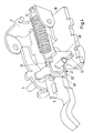
- FIG. 1 shows a concrete embodiment of an embodiment of the invention electromagnetic release system 1, as it is in Fig. 3 is shown schematically.
- Like reference numerals designate like elements, parts or assemblies.
- the Fig. 2 shows in a detailed view of the cover plate 18 of an electromagnetic tripping system according to the invention Fig. 1 .
- Like reference numerals designate like elements, parts or assemblies.
- the Fesselarm 41 of the control lever 7 is designed in the form of a plate and mounted transversely to the longitudinal direction of the trained as an elongated strip trigger arm 40 thereon. He wears at its free longitudinal edge an approximately rectangular recess, on the side walls, the two hooks of the first and second coupling point 8, 11 are formed by punching and bending.
- the support web 39 also carries such ears with expressed stub axles which serve as bearings, so that the control lever 7, can be pivotally connected.
- a fastening web 19 is welded to the cover plate 18 in the form of a bracket. This carries at its free end a hook which forms the third coupling point for the auxiliary spring 12.
- the attachment of the ear-shaped projections 42 for receiving the pivot axis has something to do with the mechanical design already described above.
- the ear-shaped extensions ensure that the line of action of the force exerted by the additional spring 12 on the control lever 7, is already shifted at a very small pivoting from the rest position clockwise in the axis of rotation of the pivot axis 6 and thus no further rotation of the control lever effective restoring force exerts more on the control lever.
- the auxiliary spring can even after overcoming the dead center, which is formed by the fact that the line of action of the force of the auxiliary spring 12 is located in the pivot axis 6, apply an additional torque and thus support a rotation of the control lever 7 in its release position in a clockwise direction ,
- the additional spring 12 counteracts due to this construction only in the first moment of the incipient rotation of the control part counterclockwise.
- it increases the restraint force on the control lever 12 only at the beginning of the triggering operation, in the further course of the contact opening process, it has no influence on the contact opening force.
- the electromagnetic tripping system would have the tripping characteristic, which is predetermined by the restraint spring 9 alone, for example, an E-characteristic.
- the attachment web 19 can either be basically welded to all cover plates, and then remains unused in the devices with E-characteristics. But it can also be welded to the mounting plate only on the cover plates of those electromagnetic tripping systems, which are provided for use with additional spring 12. Overall, an inventive electromagnetic trip system is thus highly variable configurable with minimal change intervention.
- FIG. 4 shows a further embodiment of an electromagnetic tripping system according to the invention.
- the same or equivalent components, assemblies or systems bear the same reference numerals as in the preceding figures.
- the cover plate 18 of the release system is shown, with the contact lever 5 and the housing-fixed axis 4, and the control lever 7.
- the fetlock spring, the pivot axis for the control lever and the retaining bar are in the FIG. 4 for the sake of clarity not shown.
- the embodiment according to Fig. 4 is different from the one in the FIGS. 1 and 2 and 3 is shown, characterized in that the third coupling point 13 is located on a spring-holding part 47.
- the spring-holding part 47 has a holding leg 48 in the form of a rectangular plate, on whose one narrow side a perpendicular thereto projecting support leg 49 is formed.
- the third coupling point 13 is formed in the form of an eye-like depression on an upper narrow side of the retaining leg 48, in which the end of the auxiliary spring 12 is hooked.
- the holding leg 48 carries a central recess 50, here a hole, with which it is pushed onto an end piece of the housing-fixed axis 4.
- the holding leg 48 of the spring-holding member 47 carries laterally perpendicular to the housing-fixed axis 4 in the direction of the cover plate 18 toward supporting legs 49. This is dimensioned so that it up to a stop 51, which attached to the top of the cover plate 18 is, extends and applies against this when the auxiliary spring 12, the spring-holding member 47 acts clockwise.
- the spring-holding member 47 may advantageously be made as a stamped and bent part, in which the hole 50 and the support leg 49 in one operation with or are attached.
- the stop 51 can also be punched or stamped out of the cover plate 18 in the production of the cover plate 18, or it is then glued as a small block on the cover plate, welded, soldered or screwed, or to another, known in principle, Art attached.
- the stop 51 is embossed from the cover plate 18, so it is designed as part of the cover plate 18.
Landscapes
- Physics & Mathematics (AREA)
- Electromagnetism (AREA)
- Breakers (AREA)
- Driving Mechanisms And Operating Circuits Of Arc-Extinguishing High-Tension Switches (AREA)
Applications Claiming Priority (4)
| Application Number | Priority Date | Filing Date | Title |
|---|---|---|---|
| DE102009018357 | 2009-04-23 | ||
| DE102009034335 | 2009-07-23 | ||
| DE102009048798 | 2009-10-08 | ||
| DE102010004641.8A DE102010004641B4 (de) | 2009-04-23 | 2010-01-13 | Elektromagnetisches Auslösesystem und Installationsschaltgerät mit einem elektromagnetischen Auslösesystem |
Publications (2)
| Publication Number | Publication Date |
|---|---|
| EP2244276A2 true EP2244276A2 (fr) | 2010-10-27 |
| EP2244276A3 EP2244276A3 (fr) | 2013-02-20 |
Family
ID=42269853
Family Applications (1)
| Application Number | Title | Priority Date | Filing Date |
|---|---|---|---|
| EP10002205A Withdrawn EP2244276A3 (fr) | 2009-04-23 | 2010-03-04 | Système de déclenchement électromagnétique et commutateur d'installation doté d'un système de déclenchement électromagnétique |
Country Status (3)
| Country | Link |
|---|---|
| EP (1) | EP2244276A3 (fr) |
| CN (1) | CN101872702B (fr) |
| DE (1) | DE102010004641B4 (fr) |
Cited By (1)
| Publication number | Priority date | Publication date | Assignee | Title |
|---|---|---|---|---|
| CN104851757A (zh) * | 2014-02-18 | 2015-08-19 | 通用电气公司 | 三重稳定挠曲机构 |
Citations (1)
| Publication number | Priority date | Publication date | Assignee | Title |
|---|---|---|---|---|
| DE102008021768A1 (de) | 2007-04-30 | 2008-11-27 | Abb Ag | Elektromagnetischer Auslöser |
Family Cites Families (7)
| Publication number | Priority date | Publication date | Assignee | Title |
|---|---|---|---|---|
| DE511452C (de) * | 1928-06-21 | 1930-11-01 | Siemens Schuckertwerke Akt Ges | Selbsttaetiger Schalter fuer Gleichstrom |
| DE3021867A1 (de) * | 1980-06-11 | 1981-12-17 | Brown, Boveri & Cie Ag, 6800 Mannheim | Selbstschalter |
| CH672036A5 (fr) * | 1986-12-23 | 1989-10-13 | Sprecher & Schuh Ag | |
| DE9408669U1 (de) * | 1994-05-26 | 1994-07-14 | Siemens AG, 80333 München | Haltemagnetauslöser für Schutzschaltgeräte, insbesondere für Fehlerstromschutzschalter |
| DE102005041231B4 (de) * | 2005-08-31 | 2009-11-26 | Abb Ag | Elektrisches Schaltgerät |
| DE102006011982B4 (de) * | 2005-10-26 | 2009-04-02 | Abb Ag | Elektrisches Schaltgerät |
| DE102006037225A1 (de) * | 2006-08-09 | 2008-02-14 | Siemens Ag | Schalt-Einheit |
-
2010
- 2010-01-13 DE DE102010004641.8A patent/DE102010004641B4/de active Active
- 2010-03-04 EP EP10002205A patent/EP2244276A3/fr not_active Withdrawn
- 2010-03-19 CN CN201010196122.4A patent/CN101872702B/zh active Active
Patent Citations (1)
| Publication number | Priority date | Publication date | Assignee | Title |
|---|---|---|---|---|
| DE102008021768A1 (de) | 2007-04-30 | 2008-11-27 | Abb Ag | Elektromagnetischer Auslöser |
Cited By (2)
| Publication number | Priority date | Publication date | Assignee | Title |
|---|---|---|---|---|
| CN104851757A (zh) * | 2014-02-18 | 2015-08-19 | 通用电气公司 | 三重稳定挠曲机构 |
| CN104851757B (zh) * | 2014-02-18 | 2019-06-11 | 通用电气公司 | 三重稳定挠曲机构 |
Also Published As
| Publication number | Publication date |
|---|---|
| DE102010004641A1 (de) | 2010-11-11 |
| DE102010004641B4 (de) | 2021-02-18 |
| EP2244276A3 (fr) | 2013-02-20 |
| CN101872702A (zh) | 2010-10-27 |
| CN101872702B (zh) | 2014-09-17 |
Similar Documents
| Publication | Publication Date | Title |
|---|---|---|
| DE102015213375B4 (de) | Thermische Überlast-Auslösevorrichtung und Schutzschaltgerät | |
| DE1588269C3 (de) | Stromunterbrecher | |
| DE102008039187B4 (de) | Leistungsschalter, insbesondere für Niederspannungen | |
| DE102010035857B4 (de) | Installationsschaltgerät mit einem Magnetsystem | |
| DE1588263A1 (de) | Einstellbarer Stromausloeser | |
| EP2634788B1 (fr) | Disioncteur avec serrure de verrouillage | |
| DE102011008833B4 (de) | Überstromauslöser und Installationsschaltgerät mit Überstromauslöser | |
| EP2479771A1 (fr) | Commutateur d'installation | |
| EP2479773A1 (fr) | Commutateur d'installation | |
| DE102016203506B4 (de) | Auslösevorrichtung und elektromechanisches Schutzschaltgerät | |
| DE102008016575A1 (de) | Voll-Schutzschalter | |
| DE102010004641B4 (de) | Elektromagnetisches Auslösesystem und Installationsschaltgerät mit einem elektromagnetischen Auslösesystem | |
| DE102011008829B4 (de) | Installationsschaltgerät | |
| EP2479770A1 (fr) | Commutateur d'installation | |
| DE102007010270B3 (de) | Fehlerstromschutzschalter | |
| DE102007040164A1 (de) | Schaltgerät mit einem doppelt unterbrechenden Drehkontaktsystem sowie mehrpolige Schaltgeräteanordnung | |
| EP3258231A1 (fr) | Appareil de protection électromécanique comprenant un dispositif de déclenchement contre la surcharge | |
| DE102011014061A1 (de) | Magnetsystem und Installationsschaltgerät | |
| DE102011018498A1 (de) | Elektrisches Installationsgerät und System umfassend ein Installationsschaltgerät und einen Hilfsschalter | |
| DE69833637T2 (de) | Selektiver Auslöser für Leistungsschalter | |
| EP0158241B1 (fr) | Interrupteur électrique | |
| DE102008050756A1 (de) | Auslöseeinheit für einen elektrischen Schutzschalter | |
| DE102016208578A1 (de) | Schutzeinrichtung mit einer Schmelzsicherung und Verfahren zur elektrischen Überwachung und Signalisierung der Auslösung einer Schutzeinrichtung, insbesondere einer Schmelzsicherung | |
| DE102005046640B4 (de) | Elektrisches Installationsgerät | |
| DE112024000290T5 (de) | Sofortauslösevorrichtung für einen kompaktleistungsschalter |
Legal Events
| Date | Code | Title | Description |
|---|---|---|---|
| PUAI | Public reference made under article 153(3) epc to a published international application that has entered the european phase |
Free format text: ORIGINAL CODE: 0009012 |
|
| AK | Designated contracting states |
Kind code of ref document: A2 Designated state(s): AT BE BG CH CY CZ DE DK EE ES FI FR GB GR HR HU IE IS IT LI LT LU LV MC MK MT NL NO PL PT RO SE SI SK SM TR |
|
| AX | Request for extension of the european patent |
Extension state: AL BA ME RS |
|
| PUAL | Search report despatched |
Free format text: ORIGINAL CODE: 0009013 |
|
| AK | Designated contracting states |
Kind code of ref document: A3 Designated state(s): AT BE BG CH CY CZ DE DK EE ES FI FR GB GR HR HU IE IS IT LI LT LU LV MC MK MT NL NO PL PT RO SE SI SK SM TR |
|
| AX | Request for extension of the european patent |
Extension state: AL BA ME RS |
|
| RIC1 | Information provided on ipc code assigned before grant |
Ipc: H01H 71/24 20060101AFI20130114BHEP |
|
| 17P | Request for examination filed |
Effective date: 20130807 |
|
| STAA | Information on the status of an ep patent application or granted ep patent |
Free format text: STATUS: THE APPLICATION IS DEEMED TO BE WITHDRAWN |
|
| 18D | Application deemed to be withdrawn |
Effective date: 20171003 |