EP2244225A1 - Procédé de balayage optique d'un objet et dispositif - Google Patents
Procédé de balayage optique d'un objet et dispositif Download PDFInfo
- Publication number
- EP2244225A1 EP2244225A1 EP09005787A EP09005787A EP2244225A1 EP 2244225 A1 EP2244225 A1 EP 2244225A1 EP 09005787 A EP09005787 A EP 09005787A EP 09005787 A EP09005787 A EP 09005787A EP 2244225 A1 EP2244225 A1 EP 2244225A1
- Authority
- EP
- European Patent Office
- Prior art keywords
- scanning
- images
- image
- scanned
- detection
- Prior art date
- Legal status (The legal status is an assumption and is not a legal conclusion. Google has not performed a legal analysis and makes no representation as to the accuracy of the status listed.)
- Granted
Links
- 238000000034 method Methods 0.000 title claims abstract description 37
- 238000001514 detection method Methods 0.000 claims abstract description 52
- 230000003287 optical effect Effects 0.000 claims abstract description 33
- 238000003384 imaging method Methods 0.000 claims abstract description 5
- 238000004590 computer program Methods 0.000 claims abstract description 4
- 239000002131 composite material Substances 0.000 claims description 26
- 238000012360 testing method Methods 0.000 claims description 20
- 210000001124 body fluid Anatomy 0.000 claims description 14
- 239000010839 body fluid Substances 0.000 claims description 14
- 238000005259 measurement Methods 0.000 claims description 11
- 238000012634 optical imaging Methods 0.000 claims description 5
- 238000006073 displacement reaction Methods 0.000 claims description 4
- 238000000354 decomposition reaction Methods 0.000 claims description 3
- 238000012545 processing Methods 0.000 claims description 3
- 238000004458 analytical method Methods 0.000 description 5
- 238000011161 development Methods 0.000 description 2
- 230000005284 excitation Effects 0.000 description 2
- 239000000203 mixture Substances 0.000 description 2
- 238000012935 Averaging Methods 0.000 description 1
- 230000002745 absorbent Effects 0.000 description 1
- 239000002250 absorbent Substances 0.000 description 1
- 238000010521 absorption reaction Methods 0.000 description 1
- 238000013459 approach Methods 0.000 description 1
- 239000008280 blood Substances 0.000 description 1
- 210000004369 blood Anatomy 0.000 description 1
- 230000001419 dependent effect Effects 0.000 description 1
- 230000000694 effects Effects 0.000 description 1
- 238000011156 evaluation Methods 0.000 description 1
- 239000000758 substrate Substances 0.000 description 1
Images


Classifications
-
- G—PHYSICS
- G06—COMPUTING; CALCULATING OR COUNTING
- G06T—IMAGE DATA PROCESSING OR GENERATION, IN GENERAL
- G06T3/00—Geometric image transformations in the plane of the image
- G06T3/40—Scaling of whole images or parts thereof, e.g. expanding or contracting
- G06T3/4038—Image mosaicing, e.g. composing plane images from plane sub-images
Definitions
- the invention relates to a method for optically scanning an object, in particular a test element for a body fluid, as well as a device for carrying out the method and a computer program product.
- Such methods are used to examine an object which is arranged on an object receptacle by means of an optical analysis.
- the optical scanning in this case regularly comprises a plurality of scanning steps, in which the object and a detection device used for optical analysis are displaced relative to each other into a plurality of scanning positions, in order to detect in this way a series of optical scanning images, which can be evaluated.
- an optical scanning method is used to optically analyze test or sample elements for a body fluid. Determining a test or sample element for a body fluid involves an analytical detection method in which the determination of one or more body fluids is accomplished by the optical detection of fluorescent and / or absorbent labels or molecules attached to the test or sample element for this purpose analytically specific structures bound, generated or destroyed on a substrate.
- the detection of body fluid for example blood, takes place in the region of one or more detection zones on the test element.
- the detection zones have, for example, a strip-shaped or circular extension on the sample or test element.
- test or excitation light is usually applied to the test element.
- region of the detection zone which is located in the object plane is then imaged onto a photosensitive detection surface in the image plane.
- a detection surface is provided for example by means of photodiodes or Fotomulitpliern.
- two-dimensional line sensors and three-dimensional image sensors are known with which an intensity distribution of received measuring light can be detected optically.
- the object of the invention is to provide an improved method for optically scanning an object, in particular a test element for a body fluid, and a device for carrying out the method, in which measurement uncertainties can be better addressed.
- the adjustment effort is to be reduced for the user.
- This object is achieved by a method for optically scanning an object, in particular a test element for a body fluid, according to independent claim 1 and an apparatus for performing the method according to independent claim 11.
- the invention further relates to a computer program product according to the independent claim 12.
- Advantageous embodiments of the invention are specified in dependent subclaims.
- an apparatus for optically scanning an object in particular a test element for a body fluid, with an object receptacle, an optical detection device, a displacement device that is configured, the object receptacle and the detection device is arranged on the object receptacle during optical scanning Object relative to each other in successive scanning positions to relocate, and provided to a control device which is configured to control the optical scanning according to the foregoing method.
- partial scanning regions are optically detected in the different scanning positions, the mapped partial scanning regions laterally overlapping in the object plane in which the object to be scanned overlaps, since the scanning step width is smaller than the extent of the partial scanning regions in the scanning direction the object level is.
- the scanning direction is preferably aligned substantially parallel to the sample plane.
- the scanned images can be provided in digitized form.
- the scanned images taken in adjacent scanning positions in the proposed method comprise double or multiple recorded portions of the partial scanning regions. This means that sections of the scanning range are recorded two or more times in scanned images become.
- this type of overlap is at least partially "canceled” again, in order finally to select an object measurement image in this way, which can then be further evaluated, for example to determine a body fluid. This determination is known as such in connection with the optical analysis of test or sample elements.
- a plurality of result images can be selected as object measurement images, if they are of similar good quality, for example. From this, an object measurement image can then be selected or derived, with the aid of an averaging.
- the imaging of sub-scan areas having a greater extent than the scan pitch in the object plane in the scan direction assists in imaging the object of interest or areas thereof, for example, a detection zone on a test or sample element, even in the case where the alignment of the Detection device is not optimal with respect to the object, so that, for example, comes to a lateral offset of the optical image in the image plane.
- the measurement procedure is facilitated, since not always an "optimal adjustment" is necessary, for example, after a change of a sample on the sample holder. Ultimately, this also leads to a time savings in determining multiple samples.
- a preferred embodiment of the invention provides that the respective overall brightness of the composite result images is used as a selection criterion.
- the composite result image is selected with the largest overall brightness, for which an optimized signal-to-noise ratio can be expected in order to further analyze this selected measurement image, for example with the aid of an image evaluation software.
- the composite result images are generated containing at least one scan subframe from each of the scanned images. In one embodiment, it is provided that the composite result images contain exactly one scan subframe from each of the scanned images.
- An advantageous embodiment of the invention provides that the disparate scanned images are each decomposed into stripe-shaped scanning sub-images having a stripe width which corresponds to an integer multiple of the scanning step width mapped from the object plane into the image plane.
- the stripe width of the stripe-shaped scanned images thus corresponds to a width that results when the length of the scanning step width from the object plane is imaged into the image plane by means of the optical imaging system of the detection device.
- a further development of the invention provides that the scan step width is set so that the scan step width mapped from the object plane into the image plane corresponds to an integer multiple of a width of a detection element in the detection area in the scanning direction.
- the width of a detection element corresponds, for example, to the pixel width of pixel elements which form the detection area.
- the scanned images are always imaged onto one and the same detection area area of the detection area.
- the scanned images are imaged in each scan position on the same group of detection elements of the detection surface.
- it may be a row array of detection elements. But also the image on a two-dimensional arrangement of detection elements can be provided.
- a preferred embodiment of the invention provides that the optical scanning essentially the Scheimpflug rule is performed accordingly.
- the Scheimpflug rule or Scheimpflug condition states that in an optical or photographic image, the image, lens and focus planes are either parallel to each other or intersect in a common intersection line.
- a further development of the invention can provide that during the optical scanning, the object plane and the image plane are arranged substantially parallel to each other. The scanning direction then runs essentially parallel to both planes.
- the plurality of scanned images when the plurality of scanned images are decomposed, at least part of the scanned image images are generated as scanning sub-images overlapping in a scanned image.
- two adjacent scan sub-images resulting from disassembling a scanned image include at least one scanned image area in common, which may be considered as a common image area.
- Such common image areas may be provided in one or more of the decomposed scan images.
- An advantageous embodiment of the invention provides that, when the plurality of scanned images are decomposed, at least part of the scanned image images are generated as scan sub-images that do not overlap in a scanned image.
- B block size
- the scanned image corresponding to the image area of the detection area in the image plane stored in each scanning step has the following structure: line 1 Block 1 line 2 Line 3 Block 2 Line 4 .......... .......... Line 2 (n-1) +1 Block n Line 2n ......... .......... Line 2 (N-1) +1 Block N Line 2N
- N 1.
- O 1 ⁇ 1 . 1 ⁇ ⁇ 1 . 2 ⁇ .... ⁇ 1 . n ⁇ .... ⁇ ⁇ 1 .
- O i ⁇ i . 1 ⁇ ⁇ i . 2 ⁇ .... ⁇ i . n ⁇ .... ⁇ ⁇ i . N
- O M ⁇ M . 1 ⁇ ⁇ M . 2 ⁇ .... ⁇ M . n ⁇ ... ⁇ ⁇ M . N
- ⁇ be the "join operator" where two blocks are merged by appending the first line of the second block after the last line of the first.
- the large image must be redistributed to the original scanned images before disassembling the scanned images.
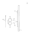
- Fig. 1 shows a schematic representation of a measuring system for optically scanning an object, in particular a test or sample element for a body fluid.
- An object 2 to be analyzed by means of optical scanning is arranged on an object receptacle 1.
- test or excitation light beams 3 are radiated onto the object 2 by a measuring light source 4, which is included together with a detector 5 by a detection device.
- the detector 5 which has an optical imaging system and a detection surface, measurement light in the form of fluorescence, reflection and / or absorption light from the sample 2 is detected, so that optical images are generated, namely scanning images, in particular as digital Image data can be captured.
- the captured image data can then be evaluated, for example for determining a body fluid.
- the sample holder 1 with the sample 2 arranged thereon and the detection device are displaced relative to one another along a scanning direction which is shown in FIG Fig. 1 is shown by an arrow A.
- scan positions a respective scan image is generated on the detector 5.
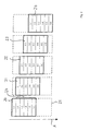
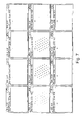
- Fig. 2 shows a schematic representation of five generated by means of optical scanning of a sample in the image plane scan images 20, ..., 24, which were generated in the optical scanning sequentially.
- the arrow A points in Fig. 2 schematic the scanning direction.
- the displacement between adjacent scanning positions was effected by a scanning step width, which corresponds in this embodiment in the image plane to the width of the partial strips of the scanning images shown.
- the scanning increment in the in Fig. 2 represented image plane in this embodiment corresponds to the width of a pixel line on the detection surface of the detector device.
- Schematically represented in Fig. 2 Furthermore, the entire scanning region 25, which is scanned in the object plane in this embodiment.
- the reference numerals 1-1, 1-2,.. Fig. 2 respective stripe-shaped portions of the scanned images 20, ..., 24 corresponding to an associated stripe on the used detection area in the image plane, that is, for example, the line width of a row array of pixels. In the illustrated embodiment, this stripe width is then also used in the decomposition of the scanned images 20, ..., 24, as described below with reference to FIG Fig. 3 will be described in more detail.
- Fig. 2 shows that at least adjacent scanned images each have an overlap region 26. This is a portion of the total sampled scan area 25 of the sample, shown in both adjacent scan images.
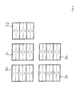
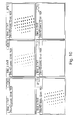
- each composite result image contains 30,..., 35 in FIG Fig. 3 exactly one stripe-shaped scanning part image from the five scanned images 20, ..., 24 in Fig. 2
- the composite result image 30 includes the respective first stripe portion from the scanned images 20, ..., 24, namely the stripe portions 1-1, 2-1, 3-1, 4-1 and 5-1.
- the composite result images 30, ..., 35 in Fig. 3 may then be analyzed for one or more selection criteria, in particular with the aid of image analysis software, to select one or more object measurement images corresponding to the one or more selection criteria.
- it can be provided from the six composite result images 30,..., 35 in FIG Fig. 3 to filter out the composite result image having the largest overall brightness.
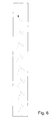
- the Fig. 4 and 5 illustrate the optical scanning method described above for a further embodiment.
- Fig. 4 were three in this embodiment Scanned images 40, 41, 42 recorded in successive scanning positions.
- the scanning increment in the in Fig. 4 represented image plane in this embodiment corresponds to the width of two rows of pixels on the detection surface of the detector device. Schematically shown in Fig. 4 also the entire scanning area 43.
- Fig. 5 shows the composition of the scanned images 40, 41, 42 in FIG Fig. 4 obtained stripe-shaped scanning part images to a plurality of composite result images 50, ..., 54, from which in turn one object measurement image can be selected according to one or more selection criteria.
Landscapes
- Physics & Mathematics (AREA)
- General Physics & Mathematics (AREA)
- Engineering & Computer Science (AREA)
- Theoretical Computer Science (AREA)
- Investigating Or Analysing Materials By Optical Means (AREA)
- Microscoopes, Condenser (AREA)
- Length Measuring Devices By Optical Means (AREA)
- Instruments For Measurement Of Length By Optical Means (AREA)
Priority Applications (8)
| Application Number | Priority Date | Filing Date | Title |
|---|---|---|---|
| EP09005787A EP2244225B1 (fr) | 2009-04-24 | 2009-04-24 | Procédé de balayage optique d'un objet et dispositif |
| AT09005787T ATE521047T1 (de) | 2009-04-24 | 2009-04-24 | Verfahren zum optischen scannen eines objektes sowie vorrichtung |
| ES09005787T ES2371721T3 (es) | 2009-04-24 | 2009-04-24 | Procedimiento y dispositivo para el escaneado óptico de un objeto. |
| CA2701310A CA2701310C (fr) | 2009-04-24 | 2010-04-23 | Methode de balayage optique d'un objet et appareil connexe |
| JP2010099818A JP5623118B2 (ja) | 2009-04-24 | 2010-04-23 | 物体を光学スキャンする方法及びその装置 |
| CN201010229188.9A CN101900669B (zh) | 2009-04-24 | 2010-04-23 | 用于光学扫描对象的方法和设备 |
| US12/766,482 US8451511B2 (en) | 2009-04-24 | 2010-04-23 | Method and device for optically scanning an object and device |
| HK11105292.1A HK1151348A1 (en) | 2009-04-24 | 2011-05-27 | Method for optical scanning an object and device |
Applications Claiming Priority (1)
| Application Number | Priority Date | Filing Date | Title |
|---|---|---|---|
| EP09005787A EP2244225B1 (fr) | 2009-04-24 | 2009-04-24 | Procédé de balayage optique d'un objet et dispositif |
Publications (2)
| Publication Number | Publication Date |
|---|---|
| EP2244225A1 true EP2244225A1 (fr) | 2010-10-27 |
| EP2244225B1 EP2244225B1 (fr) | 2011-08-17 |
Family
ID=41361205
Family Applications (1)
| Application Number | Title | Priority Date | Filing Date |
|---|---|---|---|
| EP09005787A Active EP2244225B1 (fr) | 2009-04-24 | 2009-04-24 | Procédé de balayage optique d'un objet et dispositif |
Country Status (8)
| Country | Link |
|---|---|
| US (1) | US8451511B2 (fr) |
| EP (1) | EP2244225B1 (fr) |
| JP (1) | JP5623118B2 (fr) |
| CN (1) | CN101900669B (fr) |
| AT (1) | ATE521047T1 (fr) |
| CA (1) | CA2701310C (fr) |
| ES (1) | ES2371721T3 (fr) |
| HK (1) | HK1151348A1 (fr) |
Families Citing this family (3)
| Publication number | Priority date | Publication date | Assignee | Title |
|---|---|---|---|---|
| JP2013247430A (ja) * | 2012-05-24 | 2013-12-09 | Ricoh Co Ltd | 画像処理装置および画像処理方法 |
| CN107438495B (zh) * | 2015-02-12 | 2021-02-05 | 格罗弗治公司 | 云控制激光制造 |
| TWI753865B (zh) * | 2015-11-03 | 2022-02-01 | 以色列商奧寶科技有限公司 | 用於高解析度電子圖案化的無針跡直接成像 |
Citations (4)
| Publication number | Priority date | Publication date | Assignee | Title |
|---|---|---|---|---|
| WO2001084209A2 (fr) | 2000-05-03 | 2001-11-08 | Dirk Soenksen | Numeriseur de lames de microscope rapide et entierement automatique |
| US20040051030A1 (en) | 2002-09-17 | 2004-03-18 | Artur Olszak | Method and apparatus for acquiring images from a multiple axis imaging system |
| WO2006023675A2 (fr) * | 2004-08-18 | 2006-03-02 | Tripath Imaging, Inc. | Systeme de microscopie dote de modes interactif et automatique pour former une image en mosaique agrandie et procede associe |
| EP1830218A2 (fr) * | 2006-03-01 | 2007-09-05 | Hamamatsu Photonics K.K. | Appareil de capture d'images, procédé de capture d'images et programme de capture d'images |
Family Cites Families (10)
| Publication number | Priority date | Publication date | Assignee | Title |
|---|---|---|---|---|
| US6128092A (en) * | 1999-07-13 | 2000-10-03 | National Research Council Of Canada | Method and system for high resolution ultrasonic imaging of small defects or anomalies. |
| DE10163351C1 (de) * | 2001-12-14 | 2003-06-26 | Heimann Biometric Systems Gmbh | Verfahren und Anordnung zur verzerrungsarmen Aufnahme von an einer Kontaktfläche durch gestörte Totalreflexion entstehenden Intensitätsmustern |
| US7268345B2 (en) * | 2002-04-16 | 2007-09-11 | Schultz Howard J | Optical scanner and method for 3-dimensional scanning |
| JP2004113390A (ja) * | 2002-09-25 | 2004-04-15 | Olympus Corp | 光プローブ装置 |
| US6993187B2 (en) * | 2003-02-14 | 2006-01-31 | Ikonisys, Inc. | Method and system for object recognition using fractal maps |
| JP4564768B2 (ja) * | 2004-03-23 | 2010-10-20 | 株式会社日立ハイテクノロジーズ | パターン検査方法及びその装置 |
| EP1869634B1 (fr) * | 2005-04-01 | 2008-09-10 | Koninklijke Philips Electronics N.V. | Procede, systeme et programme informatique de segmentation d'une structure dans un ensemble de donnees |
| JP2006337701A (ja) * | 2005-06-01 | 2006-12-14 | Olympus Corp | 走査型共焦点レーザ顕微鏡 |
| JP2009526272A (ja) * | 2006-02-10 | 2009-07-16 | モノジェン インコーポレイテッド | 顕微鏡媒体ベースの標本からデジタル画像データを収集するための方法および装置およびコンピュータプログラム製品 |
| US20090015875A1 (en) * | 2007-06-20 | 2009-01-15 | Ctb/Mcgraw-Hill Companies, Inc. | Image manipulation of digitized images of documents |
-
2009
- 2009-04-24 ES ES09005787T patent/ES2371721T3/es active Active
- 2009-04-24 AT AT09005787T patent/ATE521047T1/de active
- 2009-04-24 EP EP09005787A patent/EP2244225B1/fr active Active
-
2010
- 2010-04-23 JP JP2010099818A patent/JP5623118B2/ja active Active
- 2010-04-23 CN CN201010229188.9A patent/CN101900669B/zh active Active
- 2010-04-23 US US12/766,482 patent/US8451511B2/en active Active
- 2010-04-23 CA CA2701310A patent/CA2701310C/fr not_active Expired - Fee Related
-
2011
- 2011-05-27 HK HK11105292.1A patent/HK1151348A1/xx not_active IP Right Cessation
Patent Citations (4)
| Publication number | Priority date | Publication date | Assignee | Title |
|---|---|---|---|---|
| WO2001084209A2 (fr) | 2000-05-03 | 2001-11-08 | Dirk Soenksen | Numeriseur de lames de microscope rapide et entierement automatique |
| US20040051030A1 (en) | 2002-09-17 | 2004-03-18 | Artur Olszak | Method and apparatus for acquiring images from a multiple axis imaging system |
| WO2006023675A2 (fr) * | 2004-08-18 | 2006-03-02 | Tripath Imaging, Inc. | Systeme de microscopie dote de modes interactif et automatique pour former une image en mosaique agrandie et procede associe |
| EP1830218A2 (fr) * | 2006-03-01 | 2007-09-05 | Hamamatsu Photonics K.K. | Appareil de capture d'images, procédé de capture d'images et programme de capture d'images |
Also Published As
| Publication number | Publication date |
|---|---|
| EP2244225B1 (fr) | 2011-08-17 |
| CN101900669A (zh) | 2010-12-01 |
| JP5623118B2 (ja) | 2014-11-12 |
| ATE521047T1 (de) | 2011-09-15 |
| CN101900669B (zh) | 2013-01-16 |
| US8451511B2 (en) | 2013-05-28 |
| ES2371721T3 (es) | 2012-01-09 |
| HK1151348A1 (en) | 2012-01-27 |
| CA2701310C (fr) | 2014-02-18 |
| CA2701310A1 (fr) | 2010-10-24 |
| JP2010256358A (ja) | 2010-11-11 |
| US20100271670A1 (en) | 2010-10-28 |
Similar Documents
| Publication | Publication Date | Title |
|---|---|---|
| DE3726595C2 (fr) | ||
| DE102006000946B4 (de) | Verfahren und System zur Inspektion einer periodischen Struktur | |
| EP1943625B1 (fr) | Procede et dispositif de traitement d'image | |
| DE3505331C2 (de) | Verfahren und Gerät zur Vermessung des bei der Eindringhärteprüfung in einer Probe hinterlassenen Eindrucks | |
| EP1209622B1 (fr) | Méthode et dispositif pour recaler des images | |
| DE102006023843A1 (de) | Röntgen-CT-Bildrekonstruktionsverfahren und Röntgen-CT-System | |
| DE102006055408A1 (de) | Röntgen-CT-Vorrichtung | |
| WO2019229151A2 (fr) | Procédé de balayage de parties d'un échantillon au moyen d'un microscope à balayage, produit-programme informatique, support lisible par ordinateur et système de balayage de parties d'un échantillon au moyen d'un microscope à balayage | |
| DE10139832A1 (de) | Hohe-Ganghöhenrekonstruktion von Mehrfachschnitt-CT-Abtastungen | |
| EP2244225B1 (fr) | Procédé de balayage optique d'un objet et dispositif | |
| DE19748082A1 (de) | Verfahren und Vorrichtung zur Erfassung von Teilvolumen-Bildartefakten | |
| DE102008025535B4 (de) | Verfahren zur Sichtung tubulärer anatomischer Strukturen, insbesondere Gefäßstrukturen, in medizinischen 3D-Bildaufnahmen | |
| DE10009746B4 (de) | Verfahren zur Reduzierung von Strichartefakten in einem CT-Bild | |
| EP2054853B1 (fr) | Dispositif et procédé de réduction des artefacts de transition dans une image complète qui se compose d'images partielles | |
| EP2636019B1 (fr) | Procédé et dispositif d'évaluation servant à déterminer la position d'une structure se trouvant dans un objet à examiner au moyen d'une tomographie aux rayons x assistée par ordinateur | |
| DE19748081A1 (de) | Verfahren und Vorrichtung zur Bildrekonstruktion bei einem Mehrschnitt-Computer-Tomographie-System | |
| EP2131197A1 (fr) | Procédé de détermination d'une analyse dans un échantillon de liquide et dispositif d'analyse | |
| DE10307331B4 (de) | Bildgebendes Verfahren zur rechnergestützten Auswertung computer-tomographischer Messungen durch direkte iterative Rekonstruktion | |
| DE19844543A1 (de) | Zweischritt-Radon-Inversionsverarbeitung für phi-Ebenen mit lokalen Radon-Ursprüngen | |
| WO2020057849A1 (fr) | Procédé mis en œuvre par ordinateur pour la compression de données de mesure provenant d'une mesure d'un volume de mesure | |
| EP0658261B1 (fr) | Procede et dispositif de generation de donnees de lignes | |
| DE102005044652B4 (de) | Verfahren zur Erzeugung von 2D-Rekonstruktionsbildern aus einem insbesondere mittels einer Magnetresonanzeinrichtung aufgenommenen 3D-Bilddatensatz eines Untersuchungsobjekts im Rahmen der Bildnachverarbeitung | |
| DE112021007979T5 (de) | Elektrophoresedatenverarbeitungsvorrichtung und Elektrophoresedatenverarbeitungsverfahren | |
| DE102020118500A1 (de) | Mikroskop und Verfahren zum Generieren eines aus mehreren mikroskopischen Teilbildern zusammengesetzten Bildes | |
| DE102022211382A1 (de) | Röntgenprüfgerät, röntgenprüfsystem, bildverwaltungsverfahren und aufzeichnungsmedium |
Legal Events
| Date | Code | Title | Description |
|---|---|---|---|
| PUAI | Public reference made under article 153(3) epc to a published international application that has entered the european phase |
Free format text: ORIGINAL CODE: 0009012 |
|
| GRAJ | Information related to disapproval of communication of intention to grant by the applicant or resumption of examination proceedings by the epo deleted |
Free format text: ORIGINAL CODE: EPIDOSDIGR1 |
|
| GRAP | Despatch of communication of intention to grant a patent |
Free format text: ORIGINAL CODE: EPIDOSNIGR1 |
|
| 17P | Request for examination filed |
Effective date: 20100301 |
|
| AK | Designated contracting states |
Kind code of ref document: A1 Designated state(s): AT BE BG CH CY CZ DE DK EE ES FI FR GB GR HR HU IE IS IT LI LT LU LV MC MK MT NL NO PL PT RO SE SI SK TR |
|
| AX | Request for extension of the european patent |
Extension state: AL BA RS |
|
| RAP1 | Party data changed (applicant data changed or rights of an application transferred) |
Owner name: F.HOFFMANN-LA ROCHE AG Owner name: ROCHE DIAGNOSTICS GMBH |
|
| GRAS | Grant fee paid |
Free format text: ORIGINAL CODE: EPIDOSNIGR3 |
|
| GRAA | (expected) grant |
Free format text: ORIGINAL CODE: 0009210 |
|
| AK | Designated contracting states |
Kind code of ref document: B1 Designated state(s): AT BE BG CH CY CZ DE DK EE ES FI FR GB GR HR HU IE IS IT LI LT LU LV MC MK MT NL NO PL PT RO SE SI SK TR |
|
| REG | Reference to a national code |
Ref country code: GB Ref legal event code: FG4D Free format text: NOT ENGLISH |
|
| REG | Reference to a national code |
Ref country code: CH Ref legal event code: EP |
|
| REG | Reference to a national code |
Ref country code: IE Ref legal event code: FG4D Free format text: LANGUAGE OF EP DOCUMENT: GERMAN |
|
| REG | Reference to a national code |
Ref country code: DE Ref legal event code: R096 Ref document number: 502009001105 Country of ref document: DE Effective date: 20111020 |
|
| REG | Reference to a national code |
Ref country code: NL Ref legal event code: VDEP Effective date: 20110817 |
|
| REG | Reference to a national code |
Ref country code: ES Ref legal event code: FG2A Ref document number: 2371721 Country of ref document: ES Kind code of ref document: T3 Effective date: 20120109 |
|
| LTIE | Lt: invalidation of european patent or patent extension |
Effective date: 20110817 |
|
| PG25 | Lapsed in a contracting state [announced via postgrant information from national office to epo] |
Ref country code: FI Free format text: LAPSE BECAUSE OF FAILURE TO SUBMIT A TRANSLATION OF THE DESCRIPTION OR TO PAY THE FEE WITHIN THE PRESCRIBED TIME-LIMIT Effective date: 20110817 Ref country code: LT Free format text: LAPSE BECAUSE OF FAILURE TO SUBMIT A TRANSLATION OF THE DESCRIPTION OR TO PAY THE FEE WITHIN THE PRESCRIBED TIME-LIMIT Effective date: 20110817 Ref country code: IS Free format text: LAPSE BECAUSE OF FAILURE TO SUBMIT A TRANSLATION OF THE DESCRIPTION OR TO PAY THE FEE WITHIN THE PRESCRIBED TIME-LIMIT Effective date: 20111217 Ref country code: NL Free format text: LAPSE BECAUSE OF FAILURE TO SUBMIT A TRANSLATION OF THE DESCRIPTION OR TO PAY THE FEE WITHIN THE PRESCRIBED TIME-LIMIT Effective date: 20110817 Ref country code: SE Free format text: LAPSE BECAUSE OF FAILURE TO SUBMIT A TRANSLATION OF THE DESCRIPTION OR TO PAY THE FEE WITHIN THE PRESCRIBED TIME-LIMIT Effective date: 20110817 Ref country code: NO Free format text: LAPSE BECAUSE OF FAILURE TO SUBMIT A TRANSLATION OF THE DESCRIPTION OR TO PAY THE FEE WITHIN THE PRESCRIBED TIME-LIMIT Effective date: 20111117 Ref country code: PT Free format text: LAPSE BECAUSE OF FAILURE TO SUBMIT A TRANSLATION OF THE DESCRIPTION OR TO PAY THE FEE WITHIN THE PRESCRIBED TIME-LIMIT Effective date: 20111219 |
|
| PG25 | Lapsed in a contracting state [announced via postgrant information from national office to epo] |
Ref country code: LV Free format text: LAPSE BECAUSE OF FAILURE TO SUBMIT A TRANSLATION OF THE DESCRIPTION OR TO PAY THE FEE WITHIN THE PRESCRIBED TIME-LIMIT Effective date: 20110817 Ref country code: CY Free format text: LAPSE BECAUSE OF FAILURE TO SUBMIT A TRANSLATION OF THE DESCRIPTION OR TO PAY THE FEE WITHIN THE PRESCRIBED TIME-LIMIT Effective date: 20110817 Ref country code: GR Free format text: LAPSE BECAUSE OF FAILURE TO SUBMIT A TRANSLATION OF THE DESCRIPTION OR TO PAY THE FEE WITHIN THE PRESCRIBED TIME-LIMIT Effective date: 20111118 Ref country code: SI Free format text: LAPSE BECAUSE OF FAILURE TO SUBMIT A TRANSLATION OF THE DESCRIPTION OR TO PAY THE FEE WITHIN THE PRESCRIBED TIME-LIMIT Effective date: 20110817 Ref country code: PL Free format text: LAPSE BECAUSE OF FAILURE TO SUBMIT A TRANSLATION OF THE DESCRIPTION OR TO PAY THE FEE WITHIN THE PRESCRIBED TIME-LIMIT Effective date: 20110817 |
|
| REG | Reference to a national code |
Ref country code: IE Ref legal event code: FD4D |
|
| PG25 | Lapsed in a contracting state [announced via postgrant information from national office to epo] |
Ref country code: CZ Free format text: LAPSE BECAUSE OF FAILURE TO SUBMIT A TRANSLATION OF THE DESCRIPTION OR TO PAY THE FEE WITHIN THE PRESCRIBED TIME-LIMIT Effective date: 20110817 Ref country code: IE Free format text: LAPSE BECAUSE OF FAILURE TO SUBMIT A TRANSLATION OF THE DESCRIPTION OR TO PAY THE FEE WITHIN THE PRESCRIBED TIME-LIMIT Effective date: 20110817 Ref country code: SK Free format text: LAPSE BECAUSE OF FAILURE TO SUBMIT A TRANSLATION OF THE DESCRIPTION OR TO PAY THE FEE WITHIN THE PRESCRIBED TIME-LIMIT Effective date: 20110817 |
|
| PG25 | Lapsed in a contracting state [announced via postgrant information from national office to epo] |
Ref country code: RO Free format text: LAPSE BECAUSE OF FAILURE TO SUBMIT A TRANSLATION OF THE DESCRIPTION OR TO PAY THE FEE WITHIN THE PRESCRIBED TIME-LIMIT Effective date: 20110817 Ref country code: EE Free format text: LAPSE BECAUSE OF FAILURE TO SUBMIT A TRANSLATION OF THE DESCRIPTION OR TO PAY THE FEE WITHIN THE PRESCRIBED TIME-LIMIT Effective date: 20110817 |
|
| PLBE | No opposition filed within time limit |
Free format text: ORIGINAL CODE: 0009261 |
|
| STAA | Information on the status of an ep patent application or granted ep patent |
Free format text: STATUS: NO OPPOSITION FILED WITHIN TIME LIMIT |
|
| PG25 | Lapsed in a contracting state [announced via postgrant information from national office to epo] |
Ref country code: DK Free format text: LAPSE BECAUSE OF FAILURE TO SUBMIT A TRANSLATION OF THE DESCRIPTION OR TO PAY THE FEE WITHIN THE PRESCRIBED TIME-LIMIT Effective date: 20110817 |
|
| 26N | No opposition filed |
Effective date: 20120521 |
|
| PG25 | Lapsed in a contracting state [announced via postgrant information from national office to epo] |
Ref country code: HR Free format text: LAPSE BECAUSE OF FAILURE TO SUBMIT A TRANSLATION OF THE DESCRIPTION OR TO PAY THE FEE WITHIN THE PRESCRIBED TIME-LIMIT Effective date: 20120328 |
|
| REG | Reference to a national code |
Ref country code: DE Ref legal event code: R097 Ref document number: 502009001105 Country of ref document: DE Effective date: 20120521 |
|
| BERE | Be: lapsed |
Owner name: F.HOFFMANN-LA ROCHE A.G. Effective date: 20120430 Owner name: ROCHE DIAGNOSTICS G.M.B.H. Effective date: 20120430 |
|
| PG25 | Lapsed in a contracting state [announced via postgrant information from national office to epo] |
Ref country code: MC Free format text: LAPSE BECAUSE OF NON-PAYMENT OF DUE FEES Effective date: 20120430 |
|
| PG25 | Lapsed in a contracting state [announced via postgrant information from national office to epo] |
Ref country code: BE Free format text: LAPSE BECAUSE OF NON-PAYMENT OF DUE FEES Effective date: 20120430 |
|
| PG25 | Lapsed in a contracting state [announced via postgrant information from national office to epo] |
Ref country code: MK Free format text: LAPSE BECAUSE OF FAILURE TO SUBMIT A TRANSLATION OF THE DESCRIPTION OR TO PAY THE FEE WITHIN THE PRESCRIBED TIME-LIMIT Effective date: 20110817 |
|
| PG25 | Lapsed in a contracting state [announced via postgrant information from national office to epo] |
Ref country code: BG Free format text: LAPSE BECAUSE OF FAILURE TO SUBMIT A TRANSLATION OF THE DESCRIPTION OR TO PAY THE FEE WITHIN THE PRESCRIBED TIME-LIMIT Effective date: 20111117 |
|
| PG25 | Lapsed in a contracting state [announced via postgrant information from national office to epo] |
Ref country code: MT Free format text: LAPSE BECAUSE OF FAILURE TO SUBMIT A TRANSLATION OF THE DESCRIPTION OR TO PAY THE FEE WITHIN THE PRESCRIBED TIME-LIMIT Effective date: 20110817 |
|
| PG25 | Lapsed in a contracting state [announced via postgrant information from national office to epo] |
Ref country code: HR Free format text: LAPSE BECAUSE OF FAILURE TO SUBMIT A TRANSLATION OF THE DESCRIPTION OR TO PAY THE FEE WITHIN THE PRESCRIBED TIME-LIMIT Effective date: 20110817 |
|
| PG25 | Lapsed in a contracting state [announced via postgrant information from national office to epo] |
Ref country code: TR Free format text: LAPSE BECAUSE OF FAILURE TO SUBMIT A TRANSLATION OF THE DESCRIPTION OR TO PAY THE FEE WITHIN THE PRESCRIBED TIME-LIMIT Effective date: 20110817 |
|
| PG25 | Lapsed in a contracting state [announced via postgrant information from national office to epo] |
Ref country code: LU Free format text: LAPSE BECAUSE OF NON-PAYMENT OF DUE FEES Effective date: 20120424 |
|
| PG25 | Lapsed in a contracting state [announced via postgrant information from national office to epo] |
Ref country code: HU Free format text: LAPSE BECAUSE OF FAILURE TO SUBMIT A TRANSLATION OF THE DESCRIPTION OR TO PAY THE FEE WITHIN THE PRESCRIBED TIME-LIMIT Effective date: 20090424 |
|
| REG | Reference to a national code |
Ref country code: FR Ref legal event code: PLFP Year of fee payment: 8 |
|
| REG | Reference to a national code |
Ref country code: FR Ref legal event code: PLFP Year of fee payment: 9 |
|
| REG | Reference to a national code |
Ref country code: FR Ref legal event code: PLFP Year of fee payment: 10 |
|
| PGFP | Annual fee paid to national office [announced via postgrant information from national office to epo] |
Ref country code: CH Payment date: 20180425 Year of fee payment: 10 Ref country code: ES Payment date: 20180504 Year of fee payment: 10 |
|
| PGFP | Annual fee paid to national office [announced via postgrant information from national office to epo] |
Ref country code: IT Payment date: 20180412 Year of fee payment: 10 Ref country code: AT Payment date: 20180323 Year of fee payment: 10 |
|
| REG | Reference to a national code |
Ref country code: CH Ref legal event code: PL |
|
| REG | Reference to a national code |
Ref country code: AT Ref legal event code: MM01 Ref document number: 521047 Country of ref document: AT Kind code of ref document: T Effective date: 20190424 |
|
| PG25 | Lapsed in a contracting state [announced via postgrant information from national office to epo] |
Ref country code: AT Free format text: LAPSE BECAUSE OF NON-PAYMENT OF DUE FEES Effective date: 20190424 Ref country code: CH Free format text: LAPSE BECAUSE OF NON-PAYMENT OF DUE FEES Effective date: 20190430 Ref country code: LI Free format text: LAPSE BECAUSE OF NON-PAYMENT OF DUE FEES Effective date: 20190430 |
|
| PG25 | Lapsed in a contracting state [announced via postgrant information from national office to epo] |
Ref country code: IT Free format text: LAPSE BECAUSE OF NON-PAYMENT OF DUE FEES Effective date: 20190424 |
|
| REG | Reference to a national code |
Ref country code: ES Ref legal event code: FD2A Effective date: 20200901 |
|
| PG25 | Lapsed in a contracting state [announced via postgrant information from national office to epo] |
Ref country code: ES Free format text: LAPSE BECAUSE OF NON-PAYMENT OF DUE FEES Effective date: 20190425 |
|
| PGFP | Annual fee paid to national office [announced via postgrant information from national office to epo] |
Ref country code: FR Payment date: 20230320 Year of fee payment: 15 |
|
| PGFP | Annual fee paid to national office [announced via postgrant information from national office to epo] |
Ref country code: DE Payment date: 20230320 Year of fee payment: 15 |
|
| PGFP | Annual fee paid to national office [announced via postgrant information from national office to epo] |
Ref country code: GB Payment date: 20240320 Year of fee payment: 16 |