EP2244100A1 - Ultraschallempfangsmodul, Ultraschallerkennungssystem und Verfahren mit Dokumentkamera - Google Patents
Ultraschallempfangsmodul, Ultraschallerkennungssystem und Verfahren mit Dokumentkamera Download PDFInfo
- Publication number
- EP2244100A1 EP2244100A1 EP09167990A EP09167990A EP2244100A1 EP 2244100 A1 EP2244100 A1 EP 2244100A1 EP 09167990 A EP09167990 A EP 09167990A EP 09167990 A EP09167990 A EP 09167990A EP 2244100 A1 EP2244100 A1 EP 2244100A1
- Authority
- EP
- European Patent Office
- Prior art keywords
- ultrasonic signal
- ultrasonic
- threshold level
- time
- time point
- Prior art date
- Legal status (The legal status is an assumption and is not a legal conclusion. Google has not performed a legal analysis and makes no representation as to the accuracy of the status listed.)
- Withdrawn
Links
- 238000002604 ultrasonography Methods 0.000 title claims abstract description 61
- 238000000034 method Methods 0.000 title claims description 20
- 230000003247 decreasing effect Effects 0.000 claims abstract description 17
- 238000001914 filtration Methods 0.000 claims description 4
- 238000005259 measurement Methods 0.000 description 19
- 238000001514 detection method Methods 0.000 description 12
- 238000010586 diagram Methods 0.000 description 12
- 230000001737 promoting effect Effects 0.000 description 7
- 230000001902 propagating effect Effects 0.000 description 3
- 230000005540 biological transmission Effects 0.000 description 2
- 230000008859 change Effects 0.000 description 2
- 238000012986 modification Methods 0.000 description 2
- 230000004048 modification Effects 0.000 description 2
- 230000035945 sensitivity Effects 0.000 description 2
- 238000005516 engineering process Methods 0.000 description 1
- 230000007613 environmental effect Effects 0.000 description 1
- 230000002093 peripheral effect Effects 0.000 description 1
- 230000008569 process Effects 0.000 description 1
- 230000000644 propagated effect Effects 0.000 description 1
Images

Classifications
-
- G—PHYSICS
- G01—MEASURING; TESTING
- G01S—RADIO DIRECTION-FINDING; RADIO NAVIGATION; DETERMINING DISTANCE OR VELOCITY BY USE OF RADIO WAVES; LOCATING OR PRESENCE-DETECTING BY USE OF THE REFLECTION OR RERADIATION OF RADIO WAVES; ANALOGOUS ARRANGEMENTS USING OTHER WAVES
- G01S7/00—Details of systems according to groups G01S13/00, G01S15/00, G01S17/00
- G01S7/52—Details of systems according to groups G01S13/00, G01S15/00, G01S17/00 of systems according to group G01S15/00
- G01S7/523—Details of pulse systems
- G01S7/526—Receivers
- G01S7/529—Gain of receiver varied automatically during pulse-recurrence period
-
- G—PHYSICS
- G01—MEASURING; TESTING
- G01S—RADIO DIRECTION-FINDING; RADIO NAVIGATION; DETERMINING DISTANCE OR VELOCITY BY USE OF RADIO WAVES; LOCATING OR PRESENCE-DETECTING BY USE OF THE REFLECTION OR RERADIATION OF RADIO WAVES; ANALOGOUS ARRANGEMENTS USING OTHER WAVES
- G01S15/00—Systems using the reflection or reradiation of acoustic waves, e.g. sonar systems
- G01S15/02—Systems using the reflection or reradiation of acoustic waves, e.g. sonar systems using reflection of acoustic waves
- G01S15/06—Systems determining the position data of a target
- G01S15/08—Systems for measuring distance only
- G01S15/10—Systems for measuring distance only using transmission of interrupted, pulse-modulated waves
-
- G—PHYSICS
- G01—MEASURING; TESTING
- G01S—RADIO DIRECTION-FINDING; RADIO NAVIGATION; DETERMINING DISTANCE OR VELOCITY BY USE OF RADIO WAVES; LOCATING OR PRESENCE-DETECTING BY USE OF THE REFLECTION OR RERADIATION OF RADIO WAVES; ANALOGOUS ARRANGEMENTS USING OTHER WAVES
- G01S15/00—Systems using the reflection or reradiation of acoustic waves, e.g. sonar systems
- G01S15/88—Sonar systems specially adapted for specific applications
-
- G—PHYSICS
- G01—MEASURING; TESTING
- G01S—RADIO DIRECTION-FINDING; RADIO NAVIGATION; DETERMINING DISTANCE OR VELOCITY BY USE OF RADIO WAVES; LOCATING OR PRESENCE-DETECTING BY USE OF THE REFLECTION OR RERADIATION OF RADIO WAVES; ANALOGOUS ARRANGEMENTS USING OTHER WAVES
- G01S15/00—Systems using the reflection or reradiation of acoustic waves, e.g. sonar systems
- G01S15/003—Bistatic sonar systems; Multistatic sonar systems
-
- G—PHYSICS
- G01—MEASURING; TESTING
- G01S—RADIO DIRECTION-FINDING; RADIO NAVIGATION; DETERMINING DISTANCE OR VELOCITY BY USE OF RADIO WAVES; LOCATING OR PRESENCE-DETECTING BY USE OF THE REFLECTION OR RERADIATION OF RADIO WAVES; ANALOGOUS ARRANGEMENTS USING OTHER WAVES
- G01S7/00—Details of systems according to groups G01S13/00, G01S15/00, G01S17/00
- G01S7/02—Details of systems according to groups G01S13/00, G01S15/00, G01S17/00 of systems according to group G01S13/00
- G01S7/28—Details of pulse systems
- G01S7/285—Receivers
- G01S7/292—Extracting wanted echo-signals
- G01S7/2921—Extracting wanted echo-signals based on data belonging to one radar period
- G01S7/2922—Extracting wanted echo-signals based on data belonging to one radar period by using a controlled threshold
Definitions
- the present invention relates to an ultrasound detecting apparatus and an ultrasound detecting method. More particularly, the present invention relates to an apparatus and a method using an ultrasonic wave to detect a distance.
- a distance detection system uses ultrasonic waves as media for detecting a distance by using air as a transmission media, wherein a reflected ultrasonic wave is used to detect a distance from an object.
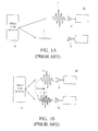
- FIG. 1A and FIG. 1B are schematic diagrams showing a conventional reflection-type ultrasound distance detection system 10.
- a conventional reflection-type ultrasound distance detection system 10 includes a transmitter 12, a receiver 14, an object 16 to be detected and a peripheral circuit (not shown).
- the object 16 to be detected is spaced from the transmitter and/or the receiver 14 at a distance desired to be measured.
- the transmitter 12 While being in operation, the transmitter 12 generates an incident wave f. A portion of incident wave f arrives at the object 16, and is reflected as a reflected wave r to the receiver 14.
- the distance desired to be detected between the object 16 and the transmitter 12 and/or the receiver 14, is computed by using a time difference value between the time point at which the incident wave f is transmitted and that at which the reflected wave r is received.
- the reflection-type ultrasound distance detection system 10 has many disadvantages.
- the signal of the reflected wave r is too weak to be detected.
- the amplitude strength of the ultrasonic wave traveling in the air will be greatly decreased with increasing traveling distance. Consequently, during a far-distance measurement, the amplitude strength of the ultrasonic wave is too weak, and the signal-to-noise ratio thereof is decreased rapidly, thus disadvantaging the measurement accuracy.
- the ultrasound receiving module includes an ultrasonic receiver, an amplifier and a detector.
- the ultrasonic receiver is used for receiving at least one ultrasonic signal.
- the amplifier is electrically connected to the ultrasonic receiver.
- the amplifier is used for providing a predetermined magnification ratio and changing an amplitude of the received ultrasonic signal with the predetermined magnification ratio, i.e., the amplifier will multiply the amplitude of the received ultrasonic signal by the predetermined magnification ratio, wherein the predetermined magnification ratio is increased with time.
- the predetermined magnification ratio provided by the amplifier is a time-varying function, and is increased with time.
- the detector is electrically connected to the amplifier for capturing a portion of the ultrasonic signal in accordance with a threshold level, wherein the portion of the ultrasonic signal captured is above the threshold level, and the threshold level is decreased with time.
- the threshold level provided by the detector also is a time-varying function, and is decreased with time.
- the ultrasound receiving module includes a processor electrically connected to the detector.
- the processor computes a transmitting distance of the ultrasonic signal in accordance with time spent for receiving the ultrasonic signal.
- the predetermined magnification ratio is a continuous time-varying function.
- the threshold level is a continuous time-varying function.
- the ultrasound detecting system has an ultrasonic transmitter, an ultrasonic receiver, an amplifier and a detector.
- the ultrasonic transmitter transmits at least one first ultrasonic signal
- the ultrasonic receiver receives at least one second ultrasonic signal, wherein the second ultrasonic signal includes the first ultrasonic signal and at least one interference signal.
- the amplifier is electrically connected to the ultrasonic receiver, and changes an amplitude of the second ultrasonic signal with a predetermined magnification ratio, wherein the predetermined magnification ratio is increased with time.
- the detector is electrically connected to the amplifier, and captures a portion of the second ultrasonic signal above a threshold level, wherein the threshold level is decreased with time.
- Another aspect of the present invention is to provide an ultrasound detecting method for promoting the measurement accuracy when the transmitting time of ultrasonic signal is shorter or longer.
- the first step of the ultrasound detecting method is to transmit at least one first ultrasonic signal.
- at least one second ultrasonic signal is received.
- a predetermined magnification ratio is used to change an amplitude of the second ultrasonic signal, wherein the predetermined magnification ratio is increased with time.
- a threshold level is used to capture a portion of the second ultrasonic signal above the threshold level, and the threshold level is decreased with time.
- a portion of the second ultrasonic signal of which a frequency is within a frequency range is filtered and obtained, wherein the frequency range contains a frequency of the first ultrasonic signal.
- a transmitting distance of the first ultrasonic signal is computed.
- Another aspect of the present invention is to provide a document camera comprising a base, a lens and an ultrasound detecting system.
- the lens is suspended on the base for capturing at least one image of at least one object to be photographed.
- the ultrasound detecting system is used for detecting a distance between the lens and the object to be photographed.
- the document camera includes a switcher.
- the switcher is electrically connected to the ultrasonic transmitter for switching between a near-distance mode and a far-distance mode, wherein the first ultrasonic signal has a first cycle number at a near-distance mode, and the first ultrasonic signal has a second cycle number at a far-distance mode, and the first cycle number is different from the second cycle number.
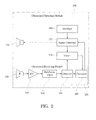
- FIG. 2 is a block diagram showing an ultrasound detecting system 100 according to an embodiment of the present invention.
- the ultrasound detecting system 100 includes an ultrasonic transmitter 110 and an ultrasound receiving module 120.
- the ultrasonic transmitter 110 is electrically connected to a signal generator 112.
- the signal generator 112 may generate an ultrasonic signal, and the ultrasonic signal is radiated into space via the ultrasonic transmitter 110.
- the ultrasonic signal transmitted from the ultrasonic transmitter 110 is referred to as a first ultrasonic signal hereinafter.
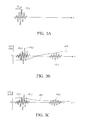
- FIG. 3A to FIG. 3C are diagrams showing the respective curves of ultrasonic signal vs. time; predetermined magnification ratio vs. time; and threshold level vs. time. Please refer to FIG. 2 and FIG. 3A simultaneously.
- the ultrasonic transmitter 110 issues a first ultrasonic signal f(t 1 ) into air space at a first time point t 1 .
- the ultrasound receiving module 120 can be used to receive and handle an ultrasonic signal.
- the ultrasound receiving module 120 includes an ultrasonic receiver 130 used for receiving ultrasonic signals.
- the ultrasonic signal received by the ultrasonic receiver 130 is referred to as a second ultrasonic signal hereinafter.
- the second ultrasonic signal includes a signal to be detected and an interference signal in an environment.
- the signal to be detected is the first ultrasonic signal f(t 1 ) which is issued from the ultrasonic transmitter 110 and received by the ultrasonic receiver 130 after propagating in space.
- the ultrasonic transmitter 110 and the ultrasonic receiver 130 can be disposed opposite to each other, and spaced at a distance, so that the ultrasonic transmitter 110 can transmit the first ultrasonic signal f(t 1 ) towards the ultrasonic receiver 130. Further, the ultrasonic transmitter 110 also can be disposed adjacent to and does not face towards the ultrasonic receiver 130. The first ultrasonic signal f(t 1 ) issued from the ultrasonic transmitter 110 is reflected by other objects to the ultrasonic receiver 130. In this embodiment, the ultrasonic transmitter 110 also can be disposed adjacent to the ultrasonic receiver 130, and the ultrasonic receiver 130 receives a returned signal reflected by other objects.
- the strength of the signal to be detected received by the ultrasonic receiver 130 will be decreased with time.
- the strength of the signal r(t 2 ) to be detected received at a second time point t 2 will be greater than the strength of the signal r(t 3 ) to be detected received at a third time point t 3 , wherein the third time point t 3 is greater than the second time point t 2 .
- the signal-to-noise ratio will decrease rapidly, thus disadvantaging the measurement accuracy.
- the ultrasonic receiver 130 will receive a crosstalk signal c(t 2 ) due to crosstalk phenomenon. Since the waveform and strength of the crosstalk signal c(t 2 ) are similar to those of the signal r(t 2 ) to be detected, thus easily causing a conventional ultrasound system to make an incorrect judgement.
- the ultrasound detecting system 100 of the present invention uses the following devices and method to resolve these problems, thereby promoting the measurement accuracy.
- An amplifier 140 is disposed in the ultrasound detecting system 100, and is electrically connected to the ultrasonic receiver 130 for changing the amplitude of the second ultrasonic signal, i.e., for enlarging or shrinking the amplitude of the second ultrasonic signal.
- the amplifier 140 uses a predetermined magnification ratio g(t) to change the amplitude of the second ultrasonic signal, wherein the predetermined magnification ratio g(t) is increased with time.
- the predetermined magnification ratio g(t) is a time-varying function and is increased with time.
- FIG. 3B is a diagram showing a curve of predetermined magnification ratio vs. time, wherein the horizontal axis stands for time, and the vertical axis stands for the predetermined magnification ratio g(t).
- the predetermined magnification ratio g(t) is a continuous time-varying function, and is increased with time. At a time point closer to the time point of origin of issuing the signal, such as at the second time point t 2 , the predetermined magnification ratio g(t) is smaller so as to suppress the interference of crosstalk signal c(t 2 ). On the other hand, at a time point farther from the time point of origin of issuing the signal, such as at the third time point t 3 , the predetermined magnification ratio g(t) is larger so as to amplify the strength of the signal r(t 3 ) to be detected.
- a detector 150 is further disposed in the ultrasound detecting system 100, and is electrically connected to the amplifier 140 for capturing a portion of the second ultrasonic signal.
- a threshold level d(t) is set in the detector 150, and the detector 150 will capture a portion of the amplified second ultrasonic signal above the threshold level d(t), wherein the threshold level d(t) is decreased with time.
- the threshold level d(t) provided by the detector 150 is a time-varying function and is decreased with time.
- FIG. 3C is a diagram showing a curve of threshold level d(t) vs. time for explaining the states of the threshold level d(t) changed with time, wherein the horizontal axis stands for time, and the vertical axis stands for the threshold level d(t).
- the threshold level d(t) is a continuous time-varying function, and is decreased with time. At a time point closer to the time point of origin of issuing the signal, such as at the second time point t 2 , the threshold level d(t) is larger so as to raise the reference value of detection, thereby preventing the crosstalk signal c(t 2 ). On the other hand, at a time point farther from the time point of origin of issuing the signal, such as at the third time point t 3 , the threshold level d(t) is smaller so as to increase the sensitivity of the signal r(t 3 ) to be detected.
- a band-pass filter 190 is further disposed in the ultrasound detecting system 100 for providing a frequency range and filtering and obtaining a portion of the second ultrasonic signal of which a frequency is within the frequency range.
- the band-pass filter 190 will set a frequency range, and keep the portion of the second ultrasonic signal of which a frequency is within the frequency range.
- the frequency range of the band-pass filter 190 includes the frequency of the first ultrasonic signal. In other words, the frequency of the first ultrasonic signal transmitted by the ultrasonic transmitter 110 falls within the frequency range.
- the frequency of the first ultrasonic signal can be 40KHZ
- the frequency range of the band-pass filter 190 can be around 40KHZ, such as between 38KHZ and 42 KHz. Accordingly, the portion of the second ultrasonic signal filtered and obtained is very likely to be the first ultrasonic signal after propagating in space.
- the band-pass filter 190 can be electrically connected to the amplifier 140 and/or the detector 150.
- the band-pass filter 190 is disposed between the amplifier 140 and the detector 150.
- the second ultrasonic signal sequentially passes through the amplifier 140 for changing its amplitude; then through the band-pass filter 190 for filtering and obtaining a portion of its frequency within a specific frequency range; and then through the detector 150 for capturing a portion of its amplitude above the threshold level d(t).
- the ultrasound detecting system 100 includes a processor 160 electrically connected to the detector 150. After the detector 150 captures the portion of the second ultrasonic signal, the processor 160 will compute a transmitting distance of the first ultrasonic signal f(t 1 ) by computing the time spent for receiving the ultrasonic signal.
- a timer 170 is disposed in the ultrasound detecting system 100. The timer 170 is electrically connected to the ultrasonic transmitter 110 for recording a time point, such as the first time point t 1 , at which the ultrasonic transmitter issues the first ultrasonic signal.
- the timer 170 is further electrically connected to the ultrasonic receiver 130 or the detector 150 for recording a time point for receiving the signal.
- the timer 170 can be electrically connected to the ultrasonic receiver 130 and record the time point at which the ultrasonic receiver 130 receives the signal.
- the timer 170 can be electrically connected to the detector 150 record the time point at which the signal including the signal r(t 2 ) to be detected is received.
- the detector 150 captures the second ultrasonic signal, meaning that the second ultrasonic signal including the signal r(t 2 ) to be detected is received, the current time point can be recorded as the second time point t 2 .
- the timer 170 is electrically connected to the detector 150.
- the process or 160 is electrically connected to the timer 170.
- the processor 160 calculates a difference value between the first time point t 1 and the second time point t 2 , and computes the transmitting distance of the first ultrasonic signal f(t 1 ) in accordance with the difference value.
- the processor 160 obtains the transmitting distance of the first ultrasonic signal f(t 1 ) by multiplying the difference value between the first time point t 1 and the second time point t 2 by the propagation speed of ultrasonic wave.
- the first ultrasonic signal f(t 1 ) issued by the ultrasonic transmitter 110 is first reflected by the object to be detected and then reaches the ultrasonic receiver 130.
- the transmitting distance of the first ultrasonic signal f(t 1 ) is the sum of the distance between the ultrasonic transmitter 110 and the object to be detected and that between the object to be detected and the ultrasonic receiver 130.
- the ultrasonic transmitter 110 is disposed tightly adjacent to the ultrasonic receiver 130, and thus the transmitting distance of the first ultrasonic signal f(t 1 ) is about twice as much as the distance between the ultrasonic transmitter 110 and the object to be detected.
- the ultrasonic transmitter 110 and the ultrasonic receiver 130 are disposed opposite to each other, and spaced at a distance.
- the transmitting distance of the first ultrasonic signal f(t 1 ) is the distance between the ultrasonic transmitter 110 and the ultrasonic receiver 130.
- the processor 160 can be electrically connected to the signal generator 112, thereby adjusting the time for generating a signal by the signal generator 112.
- the ultrasound detecting system 100 further includes a switcher 180 electrically connected to the ultrasonic transmitter 110.
- the switcher 180 is used to switch the ultrasonic transmitter 110 to the far-distance mode or the near-distance mode.
- the first ultrasonic signal f(t 1 ) issued by the ultrasonic transmitter 110 has a first cycle number.
- the first ultrasonic signal f(t 1 ) issued by the ultrasonic transmitter 110 has a second cycle number, wherein the first cycle number is different from the second cycle number.
- the situation of so-called “near-distance” or “shorter ultrasonic signal transmitting time” indicates the situation which is easily influenced by the crosstalk signal c(t 2 ). Further, the situation of so-called “far-distance” or “longer ultrasonic signal transmitting time” indicates the situation which is not easily influenced by the crosstalk signal c(t 2 ).
- the first cycle number is smaller than the second cycle number.
- the first cycle number of the first ultrasonic signal f(t 1 ) is smaller, and thus the duration of crosstalk interference can be shortened.
- the second cycle number of the first ultrasonic signal f(t 1 ) is larger, and thus the transmission energy accumulated may increase the possibility of detecting the first ultrasonic signal f(t 1 ).
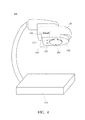
- FIG. 4 is a schematic diagram showing a document camera 400 according to another embodiment of the present invention. Please refer to FIG. 4 and FIG. 2 simultaneously.
- the document camera 400 includes a base 410, a lens 420 and the ultrasound detecting system 100.
- the description regarding the ultrasound detecting system 100 has been stated in the above, and is not repeated herein.
- the lens 420 is suspended above the base 410 for capturing an image of an object to be photographed.
- the lens 420 of the document camera 400 can be rotated to make the lens 420 face towards the base 410 or another direction for photography.
- the lens 420 may photograph an object (such as a book) lying on the base 410.
- the lens 420 also may photograph another object (such a picture hung on a wall) at the other end of the room.
- the ultrasonic transmitter 110 and the ultrasonic receiver 130 of the ultrasound detecting system 100 are disposed adjacent to the lens 420.
- the lens 420 is installed on a surface 432 of a housing 430, and the ultrasonic transmitter 110 and the ultrasonic receiver 130 are disposed on the same surface 430 and are adjacent to the lens 420, as shown in FIG. 4 . Consequently, the ultrasound detecting system 100 can be used to detect the distance between the lens 420 and the object to be photographed.
- the switcher 180 of the ultrasound detecting system 100 can be a manual switcher or an automatic switcher.
- the switcher 180 of the ultrasound detecting system 100 shown in FIG. 4 is a manual switcher, and a user may manually switch the switcher 180 to the near-distance or far-distance mode.
- the switcher 180 also can be an automatic switcher.
- a sensor is used to detect the current position of the lens 420, thereby automatically switching the switcher 180.
- sensors and their functions ap plicable to the embodiments of the present invention, which are not described in detail herein.
- the switcher 180 can be switched to the near-distance mode.
- the switcher 180 can be switched to the far-distance mode.
- the ultrasound detecting system 100 and its application such as the document camera 400 are applicable to the near-distance and far-distance measurements, thereby overcoming the restriction of the conventional measurement, promoting detection cleverness.
- FIG. 5 is a flow chart showing an ultrasound detecting method 500 according to another embodiment of the present invention.
- step 510 is performed to transmit at least one first ultrasonic signal.
- step 520 at least one second ultrasonic signal is received.
- the second ultrasonic signal includes a signal to be detected and an environmental interference signal such as a crosstalk interference signal.
- the signal to be detected means the first ultrasonic signal received after propagating in space since being transmitted at step 510.
- step 530 an amplitude of the second ultrasonic signal is changed by using a predetermined magnification ratio, wherein the predetermined magnification ratio is increased with time.
- step 540 a portion of the second ultrasonic signal of which a frequency is within a frequency range is filtered and obtained.
- a band-pass filter is used to filter the second ultrasonic signal so as to obtain the portion of the second ultrasonic signal of which a frequency is within the frequency range, wherein the frequency of the first ultrasonic signal falls within the frequency range.
- a threshold level is used to capture a portion of the second ultrasonic signal, wherein the amplitude of the second ultrasonic signal captured is greater than the threshold level, and the threshold level is decreased with time.
- step 560 is performed to compute a transmitting distance of the first ultrasonic signal.
- the transmitting distance of the first ultrasonic signal is obtained by computing the time for transmitting the first ultrasonic signal.
- the ultrasound detecting method 500 may record a first time point at which the first ultrasonic signal is issued when step 510 is performed. Then, the ultrasound detecting method 500 may record a second time point at which the second ultrasonic signal is received, or, in step 550, record a second time point at which the amplitude of the second ultrasonic signal greater than the threshold level is captured.
- the ultrasound detecting system 100 and its ultrasound detecting method 500 are suitable for use in near-distance and far-distance measurements.
- the time-varying predetermined magnification ratio, the time-varying threshold value and/or the ultrasonic signal with an adjustable cycle number the interference of crosstalk signal can be suppressed or prevented when a near-distance measurement is performed, and when a far-distance measurement is performed, the strength of the signal to be detected can be enhanced to overcome the restriction of the conventional measurement, thus promoting detection cleverness.
Landscapes
- Engineering & Computer Science (AREA)
- Radar, Positioning & Navigation (AREA)
- Remote Sensing (AREA)
- Physics & Mathematics (AREA)
- Computer Networks & Wireless Communication (AREA)
- General Physics & Mathematics (AREA)
- Acoustics & Sound (AREA)
- Measurement Of Velocity Or Position Using Acoustic Or Ultrasonic Waves (AREA)
- Focusing (AREA)
- Automatic Focus Adjustment (AREA)
- Studio Devices (AREA)
Applications Claiming Priority (1)
| Application Number | Priority Date | Filing Date | Title |
|---|---|---|---|
| TW098113773A TW201038959A (en) | 2009-04-24 | 2009-04-24 | Ultrasound-receiving module, application and detecting method thereof |
Publications (1)
| Publication Number | Publication Date |
|---|---|
| EP2244100A1 true EP2244100A1 (de) | 2010-10-27 |
Family
ID=41403888
Family Applications (1)
| Application Number | Title | Priority Date | Filing Date |
|---|---|---|---|
| EP09167990A Withdrawn EP2244100A1 (de) | 2009-04-24 | 2009-08-17 | Ultraschallempfangsmodul, Ultraschallerkennungssystem und Verfahren mit Dokumentkamera |
Country Status (4)
| Country | Link |
|---|---|
| US (1) | US20100271483A1 (de) |
| EP (1) | EP2244100A1 (de) |
| JP (1) | JP2010256317A (de) |
| TW (1) | TW201038959A (de) |
Families Citing this family (5)
| Publication number | Priority date | Publication date | Assignee | Title |
|---|---|---|---|---|
| JP2014085131A (ja) * | 2012-10-19 | 2014-05-12 | Denso Corp | 距離検出装置、および距離検出プログラム |
| TWI702595B (zh) * | 2018-03-30 | 2020-08-21 | 維呈顧問股份有限公司 | 移動噪音源的檢測系統與方法 |
| US10726863B2 (en) | 2015-04-27 | 2020-07-28 | Otocon Inc. | System and method for locating mobile noise source |
| WO2016187259A1 (en) * | 2015-05-19 | 2016-11-24 | Wal-Mart Stores, Inc. | Measurement system and method |
| CN108802740A (zh) * | 2018-06-11 | 2018-11-13 | 浙江国自机器人技术有限公司 | 一种超声波检测障碍物的方法、装置、设备及存储介质 |
Citations (4)
| Publication number | Priority date | Publication date | Assignee | Title |
|---|---|---|---|---|
| US3896411A (en) * | 1974-02-19 | 1975-07-22 | Westinghouse Electric Corp | Reverberation condition adaptive sonar receiving system and method |
| DE3937585A1 (de) * | 1989-11-11 | 1991-05-16 | Swf Auto Electric Gmbh | Einrichtung zur abstandsmessung |
| EP1139117A1 (de) * | 2000-03-14 | 2001-10-04 | Kabushiki Kaisha Toyoda Jidoshokki Seisakusho | Vorrichtung und Verfahren zur Bestimmung der Position eines beweglichen Körpers unter Verwendung von Ultraschallwellen |
| EP1783514A1 (de) * | 2005-11-01 | 2007-05-09 | Solar Wide Industrial Ltd. | Gerät und Verfahren zur Abstandsmessung mittels Ultraschall |
Family Cites Families (7)
| Publication number | Priority date | Publication date | Assignee | Title |
|---|---|---|---|---|
| US3856985A (en) * | 1973-05-17 | 1974-12-24 | Tokyo Shibaura Electric Co | Ultrasonic diagnostic apparatus |
| JPS62156587A (ja) * | 1985-12-27 | 1987-07-11 | Yokogawa Electric Corp | 超音波距離測定装置 |
| US5327894A (en) * | 1993-03-01 | 1994-07-12 | General Electric Company | Wall filter using circular convolution for a color flow imaging system |
| JPH0763845A (ja) * | 1993-08-31 | 1995-03-10 | Mazda Motor Corp | 車両の障害物検知装置 |
| JP3145592B2 (ja) * | 1994-12-16 | 2001-03-12 | カルソニックカンセイ株式会社 | 車両用障害物検知装置 |
| JPH1082855A (ja) * | 1996-09-05 | 1998-03-31 | Mazda Motor Corp | 物体測定装置 |
| JP2004045188A (ja) * | 2002-07-11 | 2004-02-12 | Matsushita Electric Ind Co Ltd | 距離測定装置 |
-
2009
- 2009-04-24 TW TW098113773A patent/TW201038959A/zh unknown
- 2009-06-17 JP JP2009144215A patent/JP2010256317A/ja active Pending
- 2009-08-17 EP EP09167990A patent/EP2244100A1/de not_active Withdrawn
- 2009-08-24 US US12/546,360 patent/US20100271483A1/en not_active Abandoned
Patent Citations (4)
| Publication number | Priority date | Publication date | Assignee | Title |
|---|---|---|---|---|
| US3896411A (en) * | 1974-02-19 | 1975-07-22 | Westinghouse Electric Corp | Reverberation condition adaptive sonar receiving system and method |
| DE3937585A1 (de) * | 1989-11-11 | 1991-05-16 | Swf Auto Electric Gmbh | Einrichtung zur abstandsmessung |
| EP1139117A1 (de) * | 2000-03-14 | 2001-10-04 | Kabushiki Kaisha Toyoda Jidoshokki Seisakusho | Vorrichtung und Verfahren zur Bestimmung der Position eines beweglichen Körpers unter Verwendung von Ultraschallwellen |
| EP1783514A1 (de) * | 2005-11-01 | 2007-05-09 | Solar Wide Industrial Ltd. | Gerät und Verfahren zur Abstandsmessung mittels Ultraschall |
Also Published As
| Publication number | Publication date |
|---|---|
| TW201038959A (en) | 2010-11-01 |
| US20100271483A1 (en) | 2010-10-28 |
| JP2010256317A (ja) | 2010-11-11 |
Similar Documents
| Publication | Publication Date | Title |
|---|---|---|
| EP2244100A1 (de) | Ultraschallempfangsmodul, Ultraschallerkennungssystem und Verfahren mit Dokumentkamera | |
| KR102157507B1 (ko) | 음향 거리 측정용 회로 | |
| HRP20221523T1 (hr) | Sustavi i postupci za otkrivanje oštećenja | |
| CN111413699A (zh) | 用于低频调制(lfm)啁啾信号的声学距离测量电路和方法 | |
| KR101850486B1 (ko) | 지능형 음원 수집 및 분석을 이용한 음원 방향 탐지 시스템 및 그 방법 | |
| JP6715456B2 (ja) | 検出装置、検出方法、および検出プログラム | |
| JP2534698B2 (ja) | 管内検査ピグ装置 | |
| JP2011112416A (ja) | 車両周辺監視装置 | |
| JP2019079188A (ja) | 物体検知装置 | |
| US20240004066A1 (en) | Method for characterising an object in an environment of a motor vehicle | |
| JP6309328B2 (ja) | 車両の速度監視方法および装置 | |
| CN101782648B (zh) | 超音波接收模块、侦测系统及其侦测方法和实物摄影机 | |
| CN107770519B (zh) | 一种基于光点检测的相机成像管理方法 | |
| CN214795189U (zh) | 测距装置、接收机及终端 | |
| CN115684352B (zh) | 一种集装箱空箱声学智能检测方法及系统 | |
| JP7634321B2 (ja) | 物体検出システムおよび物体検出方法 | |
| CN114720987A (zh) | 测距装置、接收机及终端 | |
| CN117916628A (zh) | 表征机动车辆周围环境中的对象的方法 | |
| JP4337421B2 (ja) | 移動する物体の位置計測方法及び位置計測システム | |
| KR101246732B1 (ko) | 수중 초음파 카메라 오작동 진단 장치 및 이를 이용한 진단 방법 | |
| JP2009270882A (ja) | 超音波流量計 | |
| KR100757102B1 (ko) | 로봇 청소기에서 거리 측정 방법 및 그 장치 | |
| CN114333394A (zh) | 一种车辆在位检测系统 | |
| CN205142411U (zh) | 倒车影像撷取装置及其系统 | |
| JPH07128347A (ja) | 光学式撮像処理型車両感知器 |
Legal Events
| Date | Code | Title | Description |
|---|---|---|---|
| PUAI | Public reference made under article 153(3) epc to a published international application that has entered the european phase |
Free format text: ORIGINAL CODE: 0009012 |
|
| 17P | Request for examination filed |
Effective date: 20090817 |
|
| AK | Designated contracting states |
Kind code of ref document: A1 Designated state(s): AT BE BG CH CY CZ DE DK EE ES FI FR GB GR HR HU IE IS IT LI LT LU LV MC MK MT NL NO PL PT RO SE SI SK SM TR |
|
| AX | Request for extension of the european patent |
Extension state: AL BA RS |
|
| RAP1 | Party data changed (applicant data changed or rights of an application transferred) |
Owner name: AVER INFORMATION INC. |
|
| STAA | Information on the status of an ep patent application or granted ep patent |
Free format text: STATUS: THE APPLICATION IS DEEMED TO BE WITHDRAWN |
|
| 18D | Application deemed to be withdrawn |
Effective date: 20140301 |