EP2243991B1 - Soupape et dispositif de commande hydraulique - Google Patents
Soupape et dispositif de commande hydraulique Download PDFInfo
- Publication number
- EP2243991B1 EP2243991B1 EP10008363.3A EP10008363A EP2243991B1 EP 2243991 B1 EP2243991 B1 EP 2243991B1 EP 10008363 A EP10008363 A EP 10008363A EP 2243991 B1 EP2243991 B1 EP 2243991B1
- Authority
- EP
- European Patent Office
- Prior art keywords
- valve
- piston
- control
- stop
- pin
- Prior art date
- Legal status (The legal status is an assumption and is not a legal conclusion. Google has not performed a legal analysis and makes no representation as to the accuracy of the status listed.)
- Not-in-force
Links
Images

Classifications
-
- F—MECHANICAL ENGINEERING; LIGHTING; HEATING; WEAPONS; BLASTING
- F15—FLUID-PRESSURE ACTUATORS; HYDRAULICS OR PNEUMATICS IN GENERAL
- F15B—SYSTEMS ACTING BY MEANS OF FLUIDS IN GENERAL; FLUID-PRESSURE ACTUATORS, e.g. SERVOMOTORS; DETAILS OF FLUID-PRESSURE SYSTEMS, NOT OTHERWISE PROVIDED FOR
- F15B11/00—Servomotor systems without provision for follow-up action; Circuits therefor
- F15B11/02—Systems essentially incorporating special features for controlling the speed or actuating force of an output member
- F15B11/04—Systems essentially incorporating special features for controlling the speed or actuating force of an output member for controlling the speed
- F15B11/044—Systems essentially incorporating special features for controlling the speed or actuating force of an output member for controlling the speed by means in the return line, i.e. "meter out"
-
- B—PERFORMING OPERATIONS; TRANSPORTING
- B22—CASTING; POWDER METALLURGY
- B22D—CASTING OF METALS; CASTING OF OTHER SUBSTANCES BY THE SAME PROCESSES OR DEVICES
- B22D17/00—Pressure die casting or injection die casting, i.e. casting in which the metal is forced into a mould under high pressure
- B22D17/20—Accessories: Details
- B22D17/32—Controlling equipment
-
- F—MECHANICAL ENGINEERING; LIGHTING; HEATING; WEAPONS; BLASTING
- F15—FLUID-PRESSURE ACTUATORS; HYDRAULICS OR PNEUMATICS IN GENERAL
- F15B—SYSTEMS ACTING BY MEANS OF FLUIDS IN GENERAL; FLUID-PRESSURE ACTUATORS, e.g. SERVOMOTORS; DETAILS OF FLUID-PRESSURE SYSTEMS, NOT OTHERWISE PROVIDED FOR
- F15B11/00—Servomotor systems without provision for follow-up action; Circuits therefor
- F15B11/02—Systems essentially incorporating special features for controlling the speed or actuating force of an output member
- F15B11/024—Systems essentially incorporating special features for controlling the speed or actuating force of an output member by means of differential connection of the servomotor lines, e.g. regenerative circuits
-
- F—MECHANICAL ENGINEERING; LIGHTING; HEATING; WEAPONS; BLASTING
- F16—ENGINEERING ELEMENTS AND UNITS; GENERAL MEASURES FOR PRODUCING AND MAINTAINING EFFECTIVE FUNCTIONING OF MACHINES OR INSTALLATIONS; THERMAL INSULATION IN GENERAL
- F16K—VALVES; TAPS; COCKS; ACTUATING-FLOATS; DEVICES FOR VENTING OR AERATING
- F16K31/00—Actuating devices; Operating means; Releasing devices
- F16K31/12—Actuating devices; Operating means; Releasing devices actuated by fluid
- F16K31/122—Actuating devices; Operating means; Releasing devices actuated by fluid the fluid acting on a piston
- F16K31/124—Actuating devices; Operating means; Releasing devices actuated by fluid the fluid acting on a piston servo actuated
-
- F—MECHANICAL ENGINEERING; LIGHTING; HEATING; WEAPONS; BLASTING
- F16—ENGINEERING ELEMENTS AND UNITS; GENERAL MEASURES FOR PRODUCING AND MAINTAINING EFFECTIVE FUNCTIONING OF MACHINES OR INSTALLATIONS; THERMAL INSULATION IN GENERAL
- F16K—VALVES; TAPS; COCKS; ACTUATING-FLOATS; DEVICES FOR VENTING OR AERATING
- F16K31/00—Actuating devices; Operating means; Releasing devices
- F16K31/12—Actuating devices; Operating means; Releasing devices actuated by fluid
- F16K31/16—Actuating devices; Operating means; Releasing devices actuated by fluid with a mechanism, other than pulling-or pushing-rod, between fluid motor and closure member
- F16K31/163—Actuating devices; Operating means; Releasing devices actuated by fluid with a mechanism, other than pulling-or pushing-rod, between fluid motor and closure member the fluid acting on a piston
-
- F—MECHANICAL ENGINEERING; LIGHTING; HEATING; WEAPONS; BLASTING
- F15—FLUID-PRESSURE ACTUATORS; HYDRAULICS OR PNEUMATICS IN GENERAL
- F15B—SYSTEMS ACTING BY MEANS OF FLUIDS IN GENERAL; FLUID-PRESSURE ACTUATORS, e.g. SERVOMOTORS; DETAILS OF FLUID-PRESSURE SYSTEMS, NOT OTHERWISE PROVIDED FOR
- F15B2211/00—Circuits for servomotor systems
- F15B2211/20—Fluid pressure source, e.g. accumulator or variable axial piston pump
- F15B2211/205—Systems with pumps
- F15B2211/2053—Type of pump
- F15B2211/20538—Type of pump constant capacity
-
- F—MECHANICAL ENGINEERING; LIGHTING; HEATING; WEAPONS; BLASTING
- F15—FLUID-PRESSURE ACTUATORS; HYDRAULICS OR PNEUMATICS IN GENERAL
- F15B—SYSTEMS ACTING BY MEANS OF FLUIDS IN GENERAL; FLUID-PRESSURE ACTUATORS, e.g. SERVOMOTORS; DETAILS OF FLUID-PRESSURE SYSTEMS, NOT OTHERWISE PROVIDED FOR
- F15B2211/00—Circuits for servomotor systems
- F15B2211/20—Fluid pressure source, e.g. accumulator or variable axial piston pump
- F15B2211/205—Systems with pumps
- F15B2211/20576—Systems with pumps with multiple pumps
-
- F—MECHANICAL ENGINEERING; LIGHTING; HEATING; WEAPONS; BLASTING
- F15—FLUID-PRESSURE ACTUATORS; HYDRAULICS OR PNEUMATICS IN GENERAL
- F15B—SYSTEMS ACTING BY MEANS OF FLUIDS IN GENERAL; FLUID-PRESSURE ACTUATORS, e.g. SERVOMOTORS; DETAILS OF FLUID-PRESSURE SYSTEMS, NOT OTHERWISE PROVIDED FOR
- F15B2211/00—Circuits for servomotor systems
- F15B2211/30—Directional control
- F15B2211/305—Directional control characterised by the type of valves
- F15B2211/30505—Non-return valves, i.e. check valves
-
- F—MECHANICAL ENGINEERING; LIGHTING; HEATING; WEAPONS; BLASTING
- F15—FLUID-PRESSURE ACTUATORS; HYDRAULICS OR PNEUMATICS IN GENERAL
- F15B—SYSTEMS ACTING BY MEANS OF FLUIDS IN GENERAL; FLUID-PRESSURE ACTUATORS, e.g. SERVOMOTORS; DETAILS OF FLUID-PRESSURE SYSTEMS, NOT OTHERWISE PROVIDED FOR
- F15B2211/00—Circuits for servomotor systems
- F15B2211/30—Directional control
- F15B2211/305—Directional control characterised by the type of valves
- F15B2211/30525—Directional control valves, e.g. 4/3-directional control valve
- F15B2211/3053—In combination with a pressure compensating valve
- F15B2211/3054—In combination with a pressure compensating valve the pressure compensating valve is arranged between directional control valve and output member
-
- F—MECHANICAL ENGINEERING; LIGHTING; HEATING; WEAPONS; BLASTING
- F15—FLUID-PRESSURE ACTUATORS; HYDRAULICS OR PNEUMATICS IN GENERAL
- F15B—SYSTEMS ACTING BY MEANS OF FLUIDS IN GENERAL; FLUID-PRESSURE ACTUATORS, e.g. SERVOMOTORS; DETAILS OF FLUID-PRESSURE SYSTEMS, NOT OTHERWISE PROVIDED FOR
- F15B2211/00—Circuits for servomotor systems
- F15B2211/30—Directional control
- F15B2211/31—Directional control characterised by the positions of the valve element
- F15B2211/3105—Neutral or centre positions
- F15B2211/3111—Neutral or centre positions the pump port being closed in the centre position, e.g. so-called closed centre
-
- F—MECHANICAL ENGINEERING; LIGHTING; HEATING; WEAPONS; BLASTING
- F15—FLUID-PRESSURE ACTUATORS; HYDRAULICS OR PNEUMATICS IN GENERAL
- F15B—SYSTEMS ACTING BY MEANS OF FLUIDS IN GENERAL; FLUID-PRESSURE ACTUATORS, e.g. SERVOMOTORS; DETAILS OF FLUID-PRESSURE SYSTEMS, NOT OTHERWISE PROVIDED FOR
- F15B2211/00—Circuits for servomotor systems
- F15B2211/30—Directional control
- F15B2211/31—Directional control characterised by the positions of the valve element
- F15B2211/3122—Special positions other than the pump port being connected to working ports or the working ports being connected to the return line
- F15B2211/3133—Regenerative position connecting the working ports or connecting the working ports to the pump, e.g. for high-speed approach stroke
-
- F—MECHANICAL ENGINEERING; LIGHTING; HEATING; WEAPONS; BLASTING
- F15—FLUID-PRESSURE ACTUATORS; HYDRAULICS OR PNEUMATICS IN GENERAL
- F15B—SYSTEMS ACTING BY MEANS OF FLUIDS IN GENERAL; FLUID-PRESSURE ACTUATORS, e.g. SERVOMOTORS; DETAILS OF FLUID-PRESSURE SYSTEMS, NOT OTHERWISE PROVIDED FOR
- F15B2211/00—Circuits for servomotor systems
- F15B2211/30—Directional control
- F15B2211/32—Directional control characterised by the type of actuation
- F15B2211/327—Directional control characterised by the type of actuation electrically or electronically
-
- F—MECHANICAL ENGINEERING; LIGHTING; HEATING; WEAPONS; BLASTING
- F15—FLUID-PRESSURE ACTUATORS; HYDRAULICS OR PNEUMATICS IN GENERAL
- F15B—SYSTEMS ACTING BY MEANS OF FLUIDS IN GENERAL; FLUID-PRESSURE ACTUATORS, e.g. SERVOMOTORS; DETAILS OF FLUID-PRESSURE SYSTEMS, NOT OTHERWISE PROVIDED FOR
- F15B2211/00—Circuits for servomotor systems
- F15B2211/40—Flow control
- F15B2211/405—Flow control characterised by the type of flow control means or valve
- F15B2211/40507—Flow control characterised by the type of flow control means or valve with constant throttles or orifices
-
- F—MECHANICAL ENGINEERING; LIGHTING; HEATING; WEAPONS; BLASTING
- F15—FLUID-PRESSURE ACTUATORS; HYDRAULICS OR PNEUMATICS IN GENERAL
- F15B—SYSTEMS ACTING BY MEANS OF FLUIDS IN GENERAL; FLUID-PRESSURE ACTUATORS, e.g. SERVOMOTORS; DETAILS OF FLUID-PRESSURE SYSTEMS, NOT OTHERWISE PROVIDED FOR
- F15B2211/00—Circuits for servomotor systems
- F15B2211/40—Flow control
- F15B2211/405—Flow control characterised by the type of flow control means or valve
- F15B2211/40515—Flow control characterised by the type of flow control means or valve with variable throttles or orifices
-
- F—MECHANICAL ENGINEERING; LIGHTING; HEATING; WEAPONS; BLASTING
- F15—FLUID-PRESSURE ACTUATORS; HYDRAULICS OR PNEUMATICS IN GENERAL
- F15B—SYSTEMS ACTING BY MEANS OF FLUIDS IN GENERAL; FLUID-PRESSURE ACTUATORS, e.g. SERVOMOTORS; DETAILS OF FLUID-PRESSURE SYSTEMS, NOT OTHERWISE PROVIDED FOR
- F15B2211/00—Circuits for servomotor systems
- F15B2211/40—Flow control
- F15B2211/415—Flow control characterised by the connections of the flow control means in the circuit
- F15B2211/41509—Flow control characterised by the connections of the flow control means in the circuit being connected to a pressure source and a directional control valve
-
- F—MECHANICAL ENGINEERING; LIGHTING; HEATING; WEAPONS; BLASTING
- F15—FLUID-PRESSURE ACTUATORS; HYDRAULICS OR PNEUMATICS IN GENERAL
- F15B—SYSTEMS ACTING BY MEANS OF FLUIDS IN GENERAL; FLUID-PRESSURE ACTUATORS, e.g. SERVOMOTORS; DETAILS OF FLUID-PRESSURE SYSTEMS, NOT OTHERWISE PROVIDED FOR
- F15B2211/00—Circuits for servomotor systems
- F15B2211/40—Flow control
- F15B2211/415—Flow control characterised by the connections of the flow control means in the circuit
- F15B2211/41527—Flow control characterised by the connections of the flow control means in the circuit being connected to an output member and a directional control valve
-
- F—MECHANICAL ENGINEERING; LIGHTING; HEATING; WEAPONS; BLASTING
- F15—FLUID-PRESSURE ACTUATORS; HYDRAULICS OR PNEUMATICS IN GENERAL
- F15B—SYSTEMS ACTING BY MEANS OF FLUIDS IN GENERAL; FLUID-PRESSURE ACTUATORS, e.g. SERVOMOTORS; DETAILS OF FLUID-PRESSURE SYSTEMS, NOT OTHERWISE PROVIDED FOR
- F15B2211/00—Circuits for servomotor systems
- F15B2211/40—Flow control
- F15B2211/42—Flow control characterised by the type of actuation
- F15B2211/428—Flow control characterised by the type of actuation actuated by fluid pressure
-
- F—MECHANICAL ENGINEERING; LIGHTING; HEATING; WEAPONS; BLASTING
- F15—FLUID-PRESSURE ACTUATORS; HYDRAULICS OR PNEUMATICS IN GENERAL
- F15B—SYSTEMS ACTING BY MEANS OF FLUIDS IN GENERAL; FLUID-PRESSURE ACTUATORS, e.g. SERVOMOTORS; DETAILS OF FLUID-PRESSURE SYSTEMS, NOT OTHERWISE PROVIDED FOR
- F15B2211/00—Circuits for servomotor systems
- F15B2211/40—Flow control
- F15B2211/45—Control of bleed-off flow, e.g. control of bypass flow to the return line
-
- F—MECHANICAL ENGINEERING; LIGHTING; HEATING; WEAPONS; BLASTING
- F15—FLUID-PRESSURE ACTUATORS; HYDRAULICS OR PNEUMATICS IN GENERAL
- F15B—SYSTEMS ACTING BY MEANS OF FLUIDS IN GENERAL; FLUID-PRESSURE ACTUATORS, e.g. SERVOMOTORS; DETAILS OF FLUID-PRESSURE SYSTEMS, NOT OTHERWISE PROVIDED FOR
- F15B2211/00—Circuits for servomotor systems
- F15B2211/40—Flow control
- F15B2211/46—Control of flow in the return line, i.e. meter-out control
-
- F—MECHANICAL ENGINEERING; LIGHTING; HEATING; WEAPONS; BLASTING
- F15—FLUID-PRESSURE ACTUATORS; HYDRAULICS OR PNEUMATICS IN GENERAL
- F15B—SYSTEMS ACTING BY MEANS OF FLUIDS IN GENERAL; FLUID-PRESSURE ACTUATORS, e.g. SERVOMOTORS; DETAILS OF FLUID-PRESSURE SYSTEMS, NOT OTHERWISE PROVIDED FOR
- F15B2211/00—Circuits for servomotor systems
- F15B2211/50—Pressure control
- F15B2211/505—Pressure control characterised by the type of pressure control means
- F15B2211/50509—Pressure control characterised by the type of pressure control means the pressure control means controlling a pressure upstream of the pressure control means
- F15B2211/50518—Pressure control characterised by the type of pressure control means the pressure control means controlling a pressure upstream of the pressure control means using pressure relief valves
-
- F—MECHANICAL ENGINEERING; LIGHTING; HEATING; WEAPONS; BLASTING
- F15—FLUID-PRESSURE ACTUATORS; HYDRAULICS OR PNEUMATICS IN GENERAL
- F15B—SYSTEMS ACTING BY MEANS OF FLUIDS IN GENERAL; FLUID-PRESSURE ACTUATORS, e.g. SERVOMOTORS; DETAILS OF FLUID-PRESSURE SYSTEMS, NOT OTHERWISE PROVIDED FOR
- F15B2211/00—Circuits for servomotor systems
- F15B2211/50—Pressure control
- F15B2211/555—Pressure control for assuring a minimum pressure, e.g. by using a back pressure valve
-
- F—MECHANICAL ENGINEERING; LIGHTING; HEATING; WEAPONS; BLASTING
- F15—FLUID-PRESSURE ACTUATORS; HYDRAULICS OR PNEUMATICS IN GENERAL
- F15B—SYSTEMS ACTING BY MEANS OF FLUIDS IN GENERAL; FLUID-PRESSURE ACTUATORS, e.g. SERVOMOTORS; DETAILS OF FLUID-PRESSURE SYSTEMS, NOT OTHERWISE PROVIDED FOR
- F15B2211/00—Circuits for servomotor systems
- F15B2211/60—Circuit components or control therefor
- F15B2211/63—Electronic controllers
- F15B2211/6303—Electronic controllers using input signals
- F15B2211/634—Electronic controllers using input signals representing a state of a valve
-
- F—MECHANICAL ENGINEERING; LIGHTING; HEATING; WEAPONS; BLASTING
- F15—FLUID-PRESSURE ACTUATORS; HYDRAULICS OR PNEUMATICS IN GENERAL
- F15B—SYSTEMS ACTING BY MEANS OF FLUIDS IN GENERAL; FLUID-PRESSURE ACTUATORS, e.g. SERVOMOTORS; DETAILS OF FLUID-PRESSURE SYSTEMS, NOT OTHERWISE PROVIDED FOR
- F15B2211/00—Circuits for servomotor systems
- F15B2211/60—Circuit components or control therefor
- F15B2211/635—Circuits providing pilot pressure to pilot pressure-controlled fluid circuit elements
- F15B2211/6355—Circuits providing pilot pressure to pilot pressure-controlled fluid circuit elements having valve means
-
- F—MECHANICAL ENGINEERING; LIGHTING; HEATING; WEAPONS; BLASTING
- F15—FLUID-PRESSURE ACTUATORS; HYDRAULICS OR PNEUMATICS IN GENERAL
- F15B—SYSTEMS ACTING BY MEANS OF FLUIDS IN GENERAL; FLUID-PRESSURE ACTUATORS, e.g. SERVOMOTORS; DETAILS OF FLUID-PRESSURE SYSTEMS, NOT OTHERWISE PROVIDED FOR
- F15B2211/00—Circuits for servomotor systems
- F15B2211/70—Output members, e.g. hydraulic motors or cylinders or control therefor
- F15B2211/705—Output members, e.g. hydraulic motors or cylinders or control therefor characterised by the type of output members or actuators
- F15B2211/7051—Linear output members
- F15B2211/7053—Double-acting output members
-
- F—MECHANICAL ENGINEERING; LIGHTING; HEATING; WEAPONS; BLASTING
- F15—FLUID-PRESSURE ACTUATORS; HYDRAULICS OR PNEUMATICS IN GENERAL
- F15B—SYSTEMS ACTING BY MEANS OF FLUIDS IN GENERAL; FLUID-PRESSURE ACTUATORS, e.g. SERVOMOTORS; DETAILS OF FLUID-PRESSURE SYSTEMS, NOT OTHERWISE PROVIDED FOR
- F15B2211/00—Circuits for servomotor systems
- F15B2211/70—Output members, e.g. hydraulic motors or cylinders or control therefor
- F15B2211/75—Control of speed of the output member
Definitions
- the invention relates to a valve according to the preamble of patent claim 1.
- Valves which predominantly control a flow cross-section between two fluid connections, can be constructed very simply and are usually used to control hydraulic consumers with a high volume flow requirement.
- An example of such valves are the 2/2-way cartridge valves - also referred to as logic valves - the company Bosch Rexroth AG, in the data sheet RE 21010 / 03.05 regarding the realization of directional valve functions and in the data sheet RE 21050 / 02.03 regarding the realization of Printing functions are described.
- a throttling of the flow rate for example, in the decompression of a press cylinder or for adjusting a speed of a hydraulic load, such as a casting cylinder of a die-casting machine.
- a stop pin is inserted into a control cover of the cartridge valve, which covers the mounting hole, which protrudes into a spring chamber of the cartridge valve and thus limits the stroke of the closing member.
- the immersion depth of the stop pin in the spring chamber and thus the maximum stroke of the closing member can be adjusted manually via a screw thread.
- valve (.150) / (.151) becomes e.g. in addition to the inlet valve (.110) / (111), although both valves are connected to the same end of the cylinder.
- the valves (.520) / (. 521) or (.510) / (. 511) are provided in addition to the inlet valve (.120) / (. 121).
- a hydraulic 2/2-way cartridge valve is in the CH 660 512 A5 described.
- the main stage has a control piston which has a back cavity. The bottom of the cavity abuts a piston-like insert.
- the insert is connected via a spindle with the hollow piston of a pilot valve. By turning the spindle of the hollow piston is deflected relative to the insert. As a result of this, the pilot valve allows pressure medium to escape from the rear space of the control piston, so that the insert moves until the hollow piston is returned to the central position due to this movement.
- the EP 0 384 157 A2 shows a 2/2-way cartridge valve with a valve piston and an actuating piston, which are supported directly or via an actuating pin to each other.
- the back of the valve piston is relieved to the tank.
- the actuating piston has an end face facing away from the valve piston. This is acted upon by the inlet pressure and a spring.
- the actuating piston follows the valve piston constantly and can not be adjusted to a predetermined position.
- the GB 2 162 340 A discloses a 2/2-way cartridge valve with a valve piston and with an actuator which limits an opening of the valve piston.
- the position of the actuator can be adjusted by adjusting the supply throttle valve via a pressure equilibrium, which is established between an inlet throttle valve and an outlet throttle valve.
- the valve is provided with two fluid ports and a movably guided closure member switchable between a first position in which it releases a flow area between the two fluid ports and a second position in which it blocks a fluidic communication between the two fluid ports ,
- a stop member of the closing member By a stop member of the closing member by the maximum releasable flow cross-section can be limited.
- a special feature of the present invention is that the stop member is adjustable by a remote-controlled adjusting device between different, in particular two, stop positions.
- a limitation of the flow cross-section of the valve and thus a throttling of the volume flow can be arbitrarily and in particular automatically connected via a controller.
- the limitation of the flow cross-section can be adjusted in each operating cycle of a hydraulic control, possibly even several times.
- the valve can perform other functions, such as the function of a check valve or the function of a large flow cross-section controlling switching-way valve.
- valve according to the invention is used.
- valve in addition to its ways or possibly pressure-switching function still has a remote control adjustable limit of the flow cross-section, conventional existing additional flow control valves or throttle valves can be omitted.
- a decompression function or speed control can be incorporated into valves which are needed anyway, e.g. in directional control valves or in safety valves.
- the adjusting device has a coupled to the stop member actuator, which is movable between predetermined setting positions.
- the definition of predetermined setting positions, which are approached by the actuator, allows the reproducible specification of releasable flow cross sections. Thereby, for example, assuming known pressure specifications or force specifications, a decompression time or a speed of a consumer easily and precisely be set.
- a particularly simple embodiment of the adjusting device allows a switching of the actuator between two predetermined parking positions.
- the predetermined setting position can be determined in advance in the context of manufacturing uniform and regardless of the later application. A corresponding flow cross-section can then be determined during commissioning according to the desired application.
- a stop position of the stop member which position is assumed at the predetermined setting position, can be adjusted by means of the adjustment of the pin. This allows a particularly simple adjustment of operating parameters of a hydraulic control arrangement, e.g. a speed, directly at the relevant valve.
- the stop member is adjustable by a hydraulically actuated piston.
- the hydraulically controllable piston is a very simple actuator, which has two mechanically predetermined actuating positions, in particular with the piston stops.
- the hydraulic actuation of the actuator ensures reliable control of the various parking positions.
- the control can be carried out directly from the hydraulic circuit, in particular by means of pilot valves.
- a control surface is provided on the closing member, against which a pressure prevailing in one of the fluid connections acts on the closing member in the sense of an enlargement of the flow cross-section.
- a control surface of the piston, to which it can be acted upon in the sense of a stronger limitation of the flow cross-section, is larger than the said control surface of the closing member. This ensures a secure holding of the stop position even when counteracting high pressures from the fluid connections.
- the valve has a closure member comprising the kit and a control cover, which covers a mounting kit receiving mounting hole. Between the closing member and the control cover, a spring chamber is formed, the piston is movably guided in a cylindrical cavity in the control cover, and the stop member protrudes from the piston into the spring chamber.
- a closure member comprising the kit and a control cover, which covers a mounting kit receiving mounting hole.
- a spring chamber is formed, the piston is movably guided in a cylindrical cavity in the control cover, and the stop member protrudes from the piston into the spring chamber.
- the actuator for the stop - i. the cylindrical cavity and the piston - in the control cover extends the range of application of such installation valves again in the sense of a combination of different valve functions in a valve.
- the stop can be moved far enough in the direction of the closing member, the closing member can also be kept closed against a pressure acting in the opening direction. Likewise, in a seat valve in this way a seal on the valve seat could be strengthened.
- a particularly simple and efficient construction of the control cover which also allows adjustment of the stop position, provides that a piston rod is provided on the piston, which is guided on a side facing away from the mounting hole of the control cover to the outside, that the piston and the piston rod with a continuous axial bore are provided, and that a pin is screwed into the axial bore, which projects into the spring chamber.
- a valve which is open in the normal position can be realized with little effort if a plate is provided on the stop member, against which a spring acting upon the closing member in the sense of enlarging the flow cross-section is supported.
- the valve is designed in a poppet design. This allows a simple production and a leakage oil-free barrier of one of the fluid connections.
- a further embodiment provides a measuring device with which a position of the stop member can be detected, in particular a displacement sensor or a limit switch.
- the limit switch is e.g. a stop position can be detected, in which a predetermined minimum value of the maximum releasable flow cross-section is guaranteed.
- safety regulations can be taken into account, e.g. require unrestricted valve opening in certain operating conditions.
- the stop position can be set very precisely and flexibly by means of a position measuring system in the context of a position control.
- a pilot control arrangement is provided by which a predetermined stop position of the stop member in response to a pressure in one of the fluid connections can be controlled.
- a valve can be used to avoid decompression shocks.
- the flow cross-section is limited by the stop to a low value, as long as the pressure in the consumer port is high.
- a larger, releasable flow cross-section can be set via the stop to rapidly reduce the remaining pressure.
- a pilot valve is provided for this purpose, which, depending on a pressure in one of the fluid ports, controls a connection between said fluid port and a control pressure chamber bounded by the piston.
- a pilot control valve by means of which a control pressure chamber bounded by the piston and / or the spring chamber of the closing member can each be loaded with control fluid, permits efficient control of the valve. If both the control chamber limited by the piston pressure chamber and the spring chamber are controlled via the same valve, the component cost is reduced.
- the valve according to the invention can be opened within a short time to any predetermined, reliably adjustable flow cross-section, when the stop member is designed as a hydraulic actuator and is subjected to using a displacement sensor for detecting its position of a position control.
- the at opening of the Valve available flow cross section can be specified efficiently and easily by a reference signal.
- the adjacent to the actuator oil volume dampens any vibrations.
- the damping behavior can be influenced via the position control loop.
- Such a valve is very advantageous in the control of the casting cylinder of a die-casting machine, in particular the shot phase, in which the casting cylinder is to be accelerated within a very short time to a predetermined speed.
- the closing member is designed as a stepped piston, the stepped piston bounded with an annular surface an annular space and is acted upon on the annular surface in the opening direction with a control pressure. Furthermore, by driving the annular space, the closing member can be brought to the stop member to the plant and adjusted positionally controlled via the stop member.
- valve may be configured as a lockable check valve in addition to the arbitrary limit of the degree of opening.
- two further control surfaces on opposite ends are formed on the stepped piston, both control surfaces are acted upon by a pressure in an output port and have a total surplus area in the sense of blocking the fluidic connection.
- a hydromechanical stop damping is provided between the stop member and the closing member.
- a transient process is shortened and a load of the stop member is reduced.
- the stop member can also be adjusted by an electric actuator, in particular by an electric motor in conjunction with a screw drive. Hydraulic forces, in particular bearing forces acting on bearings and translation drives can be minimized if the stop member is coupled by means of a hydraulic sequence control to the electric actuator.
- the electric drive only has to apply low actuating and holding forces in accordance with the flow forces occurring at the sequential control. It can be an electrical Drive can be used with low power and small size.
- the bearings and translation drives can be dimensioned smaller.
- Hydraulic forces occurring at the stop element can also be reduced by subjecting the stop element to a pressure prevailing in one of the fluid connections in the direction of a limitation of the releasable flow cross section.
- both the pressure forces acting on the abutment member in a spring chamber of the closing member and the hydrostatic forces acting on an abutment member on the abutment member on the abutment member can be at least partially compensated for.
- a compact design is achieved in that the electric motor is arranged laterally of the stop member, and that the closing member is connected via a guided through a longitudinal bore in the stop member pin with a position sensor.
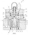
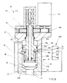
- FIG. 1 comprises a so-called logic valve, so a 2/2-way cartridge valve 10, a kit 12, which is inserted into a mounting hole 14 of a valve block 11, and a control cover 30, which covers the mounting hole 14 and the kit 12 inserted therein.
- a fluid channel 26 in the valve block 11 opens laterally into the mounting hole 14.
- a further fluid channel (not shown) in the valve block 11 opens into a bottom region of the mounting hole 14th
- the kit 12 includes a sleeve 16.
- a closing cone 18 is movably guided.
- the closing cone 18 has a blind hole-like depression 17.
- a spring 19 is inserted.
- the spring 19 is further supported on the control cover 30 and acts upon the closing cone 18 in the direction of a seat surface 20 formed in the sleeve 16.
- a control surface 23 on the closing cone 18 is acted upon by the pressure in the opening 21 with a force in the opening direction of the closing cone 18.
- Another control surface 24 is acted upon by the pending in the bores 22 pressure with a force in the opening direction.
- the closing cone 18 and the control cover 30 define a spring chamber 25.
- the closing cone 18 can be acted upon in the closing direction at its rear surface facing the opening of the installation bore 14.
- a control fluid channel 32 is provided which leads from a connection surface 31 of the control cover 30 in the spring chamber 25. Furthermore, a control fluid removal channel extends with the channel sections 27 and 34 from the fluid channel 26 to the terminal surface 31.
- the control cover 30 further comprises a cylindrical cavity is formed. This is divided by a piston 40 into a valve block 11 facing annular space 42 and a valve block 11 facing away from the annular space 44.
- the annular space 44 bounded by the piston with a control surface 65.
- the piston 40 forms a annular surface 64 of an upper stop of the piston 40.
- the bottom surface 62 of the annular space 42 forms a lower stop of the piston 40.
- the piston 40 continues into a piston rod 46, which is led out on the valve block 11 facing away from the outer surface 35 of the control cover.
- the removable cap 36 is arranged.
- the bore 48 is threaded.
- a pin 50 is screwed.
- the pin 50 is provided on a side facing away from the valve block 11 with a threaded portion through which it is fixed in the bore 48.
- a lock nut 52 secures the screw-in position of the pin 50.
- the pin 50 is guided through a bore 38 in the valve block 11 facing portion of the control cover 30 into the spring chamber 25.
- the passage of the pin 50 from the annular space 42 in the spring chamber 25 is secured by a seal 54 against an overflow of pressure medium. With a position switch 60, the position of the pin 50 can be detected.
- control fluid channel 56 leads to the connection surface 31.
- the annular space 42 is connected to the control fluid channel 58. This is continued in the valve block 11 through the control fluid channel 28.
- a spring 43 is arranged, which acts on the piston 40 with a directed away from the valve block 11 force.
- valve 10 With the closing cone 18, the fluidic connection between the opening 21 and the radial bores 22 in the sleeve 16 is controlled.
- the flow cross-section, which is released by the closing cone 18, depends on the stroke of the closing cone 18 relative to the seat surface 20.
- By acting on the spring chamber 25 with a control pressure of the closing cone 18 is controlled in per se known. For this reference is made to the already mentioned textbook “The Hydraulic Trainer Volume 4, Technology of 2-way cartridge valves”. Due to the arrangement of the spring 19, the illustrated valve 10 is closed in the unactuated normal position.
- the piston 40 can be moved in the control cover 30 between its two end stops 62 and 64 formed by the timing cover housing.
- the spring 43 moves the piston 40 at the unloaded annular space 44 to the end stop 64.
- the piston 40 can be moved against the action of the spring 43 to the end stop 62.
- the stroke of the closing cone 18 is limited by the fact that the bottom surface of the blind hole 17 on the pin 50 comes to a stop.
- the position of the piston 40 determines how far the pin 50 projects into the spring space 25.
- the stroke that the closing cone 18 can perform is minimal.
- the limitation of the stroke results in a limitation of the flow cross section, the closing cone 18 can release at most.
- the position of the pin 50 and the corresponding maximum achievable stroke of the closing cone 18 are thus arbitrarily adjustable by the control of the annular space 44 with control fluid.
- the annulus 42 is connected by channels 58 and 28 to a control fluid return line. However, it could also be the annular space 42 pressurized with control fluid.
- the piston 40 may be e.g. be biased hydraulically in the direction of the stop 64 by a pressure continuously applied in the annular space 42.
- the control surface 65 on the piston 40 is greater than the sum of the control surfaces 23 and 24 on the closing cone 18. This ensures that the piston 40 by hydraulic pressurization of the annular space 44 can be held securely against the stop 62, even if the closing cone 18 on the pin 50th is applied and transmits a force acting on the control surfaces 23 and / or 24 hydrostatic counterforce on the piston 40.
- the arrangement of the piston 40 and the pin 50 can also be used to assist in closing the closing cone 18.
- the speed can the closing movement can be increased. If the piston 40 is moved from the stop 64 to the stop 62 and is the closing cone 18 while the pin 50, so he is taken by the extension movement of the pin 50 until the piston 40 abuts against the stop 62. A remaining stroke of the closing cone 18 is usually very small. This is quickly closed due to the inertia of the moving in the closing direction closing cone 18 and by the action of the spring 19.
- the pin 50 can be adjusted so that it is applied with the closing cone 18 closed and directed in the direction of the closing cone 18 pressurization of the piston 40 on the closing cone 18 before or just when the piston 40 reaches its stop 62.
- a force acting in the closing direction of the closing cone 18 force is amplified by the pressurization of the control surface 65 of the piston 40.
- the force with which the closing cone 18 rests on the seat surface 20 can be increased.
- the sealing properties in the closed valve position can be improved.
- the valve 10 can be reliably kept closed against a pressure in the connection 21 or 22, which exceeds the available control pressure for acting on the spring chamber 19.
- the position switch 60 mechanically detects the position of the pin 50.
- the position switch 60 is shown only schematically.
- a suitable embodiment is e.g. a microswitch which is actuated by a plate attached to the pin 50.
- the position of the pin 50 can also be detected and possibly additionally with a displacement sensor. On the one hand, the reliable operation of the valve 10 can be checked. On the other hand, the position of the pin 50 can be subjected to a position control.
- the corresponding control loop includes the displacement sensor of the pin, a controller, a proportional valve that controls the control pressure chamber 44 and possibly 42, and the piston 40. This allows any stop positions for the closing cone 18 specify with high accuracy. In particular, the stop positions are no longer limited by the fact that they are predetermined by the position of the two stops 62 and 64 of the piston 40. Instead, there can be arbitrary positions within the movement scope of the piston 40 can be specified. The adjustment can also be done purely electronically by means of the setpoint specification.
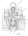
- FIG. 2 shown A further, second embodiment of the present invention is disclosed in FIG. 2 shown.
- This in FIG. 2 shown 2/2-way cartridge valve 10 largely corresponds to the in FIG. 1 illustrated 2/2-way cartridge valve. It will therefore be used for matching components the same reference numerals and omitted a repetition of the corresponding description.
- FIG. 2 shown 2/2-way cartridge valve 10 is opened in contrast to the previous embodiment in the neutral position.
- a plate 70 is provided on the pin 50, on which a spring 74 is supported.
- the spring 74 bears against a ring 72 fastened to the closing cone 18.
- the type of attachment of the ring 72 on the closing cone 18 is not shown in detail. It can be, for example, a screw connection, a press-fit, an adhesive connection or a welded connection.
- the voltage applied to the ring 72 spring 74 acts on the closing cone 18 with a force acting in the opening direction. If the spring chamber 25 is depressurized, the closing cone 18 moves in the opening direction until it comes to rest on the pin 50 or the plate 70. As in the first embodiment, the maximum achievable opening stroke of the closing cone 18 can be adjusted by the length with which the pin 50 protrudes into the spring chamber 25.
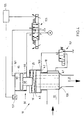
- FIG. 3 shows an application of the 2/2-way cartridge valves described in the first and second embodiments using the example of a simple press control 80.
- a press cylinder 81 With the press control 80, a press cylinder 81 is driven.
- the press cylinder 81 has a piston provided with a piston rod, which divides the cylinder interior into an annular space 82 and a cylinder space 83.
- the cylinder chamber 83 is connected via a suction valve 85 to a tank 84.
- the basic function of a press control is described in the already mentioned data sheet RD 63147 / 01.94 from Bosch Rexroth AG. In the following, especially the peculiarities that are at Use of the valves according to the invention according to the first and second embodiments, described in more detail.
- the press controller 80 includes a main pressure supply port 86 and a pilot pressure supply port 87. About tank connections 88 pressure medium is discharged. From the pump connection 86, a first branch leads to a first valve arrangement 101.
- the valve arrangement 101 consists of a mounting set 102 and a control cover 103.
- a pressure limiting valve is provided in the control cover 103 with which the pressure in the spring chamber of the installation set 102 is limited. In addition, can be relieved via a switching valve 104, the spring chamber to the tank. Accordingly, the valve assembly 101 has the function of a pilot-operated pressure relief valve to protect the pump port 86 and the function of a switching valve for switching a non-pressurized circulation.
- a further branch leads from the pump port 86 to a 4/3-way valve 105.
- This valve is used to control the direction of the press cylinder 81.
- a fluid path 106 extends to the cylinder chamber 83 of the press cylinder 81.
- From the fluid path 106 leads a branch 107 via another valve assembly 108 to the tank.
- the valve assembly 108 corresponds to the 2/2-way cartridge valve 10 according to the second exemplary embodiment (cf. Fig. 2 ).
- two pilot valves 111 and 112 are connected.
- a shuttle valve 113 selects to supply the pilot valve 112 between an internal pilot fluid tap 114 from the fluid path 106 and an external pilot pressure supply.
- the pilot valve 111 is acted upon by a spring in the direction of a first switching position, in which it the pressure chamber 44 (see. Fig. 2 ) of the arranged in the control cover 110 piston 40 relieved to the tank. In this switching position, the piston 40 (see. Fig. 2 ) on stop 64 at.
- a pressure present in the control fluid tap 114 pressurizes the pilot valve 111 in the direction of a second switching position, in which the pressure chamber 44 (cf. Fig. 2 ) is supplied with control fluid from the Steuerfluidabgriff 114.
- the piston 40 in this second switching position of the pilot valve 111, the piston 40 (see. Fig. 2 ) on the stop 62.
- the decompression of the cylinder space 83 is controlled after a pressing operation.
- the pilot valve 112 is actuated, and the kit 109 is in the closed valve position.
- the closing cone of the kit 109 (see FIG Fig. 2 ) and the decompression process begins.
- the pilot valve 111 controls the process of decompression automatically. First, the full pressing pressure is applied to the control fluid tap 114. Accordingly, the pilot valve 111 is in the second switching position.
- the piston 40 see. Fig. 2
- the pin 50 see. Fig.
- the flow rate of the pressure medium from the cylinder chamber 83 can be adjusted by adjusting the depth of engagement of the pin 50 (see. Fig. 2 ) in the bore 48 fixed.
- the pilot valve 111 switches to the first switching position and relieves the pressure chamber 44 (see. Fig. 2 ). Thereafter, the pin 50 (see. Fig. 2 ) is withdrawn from the spring chamber 25 in accordance with the movement of the piston 40, and the valve 108 releases a large flow area for rapidly reducing the residual pressure existing in the cylinder space 83.
- valve assembly 108 serves as a safety valve.
- a pressure in the cylinder chamber 83 of the press cylinder 81 can only be constructed if, on the one hand, the valve arrangement 108 is closed by actuation of the pilot control valve 112 and, on the other hand, the actuation of the switching valve 104 prevents the valve arrangement 101 from depressurized circulation.
- the pin 50 (see FIG. Fig. 2 ) of the valve assembly 108 limits the opening of the closing cone only during the decompression phase and possibly the pressing phase.
- a limit switch (see 60 in Fig. 2 ) having a retracted position of the pin 50 (see FIG. Fig. 2 ) detected.
- the annular space 82 of the press cylinder 81 is connected to the second consumer port of the directional control valve 105 through a fluid path 116 which extends in series via the valve assemblies 120 and 130.
- the valve assembly 120 has the function of a pilot-operated check valve. The unlocking takes place by actuation of the pilot valve 121.
- the valve arrangement 130 corresponds with its installation kit 131 and its control cover 132 according to the valve 10 FIG. 1 , To the control cover 132, a 4/3-way pilot valve 134 is connected. This can be electrically operated. In the neutral position of the pilot valve 134, the pressure chamber 44 (see. Fig. 1 ) and the spring chamber 25 connected to the Steuerfluidabgriff 135 of the valve assembly 130. Accordingly, the valve assembly 130 acts as a check valve. A pressure fluid flow in the direction of the pressure chamber 82 is not provided and could possibly be throttled.
- valve assembly 130 acts as a check valve.
- the piston 40 (see. Fig. 1 ) is located at its stop 64.
- the closing cone 18 (see. Fig. 1 ) can release a large flow area.
- This valve position of the pilot valve 134 is switched during a retraction phase of the piston rod of the press cylinder 81. Via the valve arrangements 130 and 120, a low-loss supply of fluid into the annular space 82 takes place.
- the series connection of the two valve arrangements 120 and 130 ensures that a technical defect in a valve arrangement does not lead to an uncontrolled lowering of the press cylinder piston.
- the position of the closing cone of the valve assembly 120 is additionally monitored by a limit switch.
- the valve arrangement 130 embodies the function of a pilot-operated check valve, with a flow restriction switched on in the unlocked state.
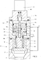
- FIG. 4 a 2/2-way cartridge valve 10 is shown.
- the 2/2-way cartridge valve 10 according to Fig. 4 has a closing cone 18 in the form of a stepped piston. This closing cone 18 controls the connection between the terminal 22 and the terminal 21.
- three control surfaces A1, A2 and A3 are present.
- the control surfaces A1 and A3 are formed by the respective end faces of the closing cone.
- the control surface A2 is the annular surface formed at a piston stage.
- the control surface A1 faces the connection 21, the control surface A3 limits the spring chamber 25.
- the control surface A2 limits an independently controllable control chamber 160, which can be acted on by a switching valve 151 with a control pressure.
- an adjustable stop is provided in the control cover 30 of the 2/2-way cartridge valve.
- This consists essentially of a piston-cylinder arrangement of the piston 40, which is movably guided in a cylindrical installation space 161.
- the pin 50 protrudes into the spring chamber 25.
- the piston 40 can be acted on at a circular surface 65 and at an annular surface 66 with a control pressure.
- the position of the piston 40 can be detected by a position sensor 157.
- the position value is fed to an electronic control unit 155.
- a proportional valve 153 By means of a proportional valve 153, the control surfaces 65 and 66 of the piston 40 can be controlled.
- the proportional valve 153 in turn is controlled by the control electronics 155.
- the regulating circuit 155 formed by the control electronics 155 the proportional valve 153, the piston 40 and the position sensor 157, the pin 50 can be adjusted in a position-controlled manner.
- switching valve 151 can be a connection between the terminal 22 and the control pressure chamber 160 to pressurize the control surface A2 produced. In the unactuated position of the switching valve 151, the control pressure chamber 160 is depressurized.
- 2/2-way cartridge valve 10 can be very quickly - within a few milliseconds - open to a predetermined by the adjustable stop 40, 50 opening cross-section.
- a preferred application is the control of the feed to a casting cylinder of a die casting machine (hot chamber die casting machine, cold chamber die casting machine), a Tixomouldingmaschine, a plastic injection molding machine or similar machines in which liquid molding material must be introduced into a mold.
- the connection 22 is connected as an input connection to a low-pressure accumulator.
- the terminal 21 is connected as an output to the casting cylinder.
- the use of a similarly constructed 2/2-way cartridge valve, but without an adjustable stop 40, 50 is in the patent application DE 10 2005 035 170.0 described. With regard to the sequence of the casting process and the non-return function of the 2/2-way cartridge valve 10, reference is made to the aforementioned application.
- a critical phase in the die casting process is the acceleration of the casting cylinder to a predetermined speed at the beginning of the firing phase.
- the adjustable stop 40, 50 can advance -. before the shooting phase - a maximum opening cross-section of the valve 10 can be adjusted.
- To initiate the firing phase of the closing cone 18 is then opened by pressing the switching valve 151 very quickly to the predetermined position by the pin 50.
- the acceleration time is in the range of about 10-20 milliseconds.
- controlled die casting machines in which the speed of the casting cylinder is controlled via the inlet, can be realized simply, cost-effectively and with high accuracy.
- the hydraulic, position-controlled adjustment of the stop allows a reliable adjustment of the opening degree with a high repeatability.
- the adjustment can be carried out efficiently from a control panel.
- the damping properties can be influenced by the control parameters in the control electronics 155.
- the damping can be improved by means of a hydraulic stop damping, which is effective between the closing cone 18 and the pin 50. For this, e.g. a known per se damping mechanism based on a hydraulic displacement use find.
- the valve 10 can also be operated as a proportionally adjustable 2-way diaphragm.
- the space 160 is subjected to a control pressure, so that the closing cone 18 bears against the pin 50.
- the opening degree can now be set arbitrarily and continuously. That's it Valve 10 - possibly in a small nominal size - also suitable to control the Vorhellphase a die-casting machine on the inlet side.
- FIG. 5 a 2/2-way cartridge valve 10 is shown with an adjustable stop pin 50.
- the 2/2-way cartridge valve 10 according to the fourth embodiment differs mainly by the type of the adjustable stop of the cartridge valves according to the first or second embodiment. Therefore, only the stop will be described below.
- the adjustable stop according to this embodiment can also be used without difficulty in the 2/2-way cartridge valve 10 according to the third embodiment.
- the maximum opening stroke of the closing cone 18 is predetermined by the stop pin 50.
- the pin 50 is designed as a piston rod and connects to the piston 40.
- the piston 40 is movably guided in a control cover 30 in a cylinder space and divides the cylinder space into the two pressure chambers 177 and 179.
- the piston 40 is provided with a central, blind hole-like bore 180.
- In the bore 180 is a pilot piston 175 before.
- the pilot piston 175 is mounted on a screw thread 173.
- the pilot piston 175 can rotate and thus adjust axially.
- a longitudinal toothing (not shown), the motor shaft 183 and the pilot piston 175 are axially decoupled.
- the pilot piston 175 has a plurality of elevations, through which the bore 180 is divided into a plurality of chambers.
- One of the chambers is connected via a radial bore in the piston 40 to a control pressure port 174.
- a further chamber Separated from this chamber by the elevation 184, there is a further chamber, which is connected via a further bore in the piston 40 to the pressure chamber 179.
- the pressure chamber 179 communicates with a discharge port 176 and also receives the spring 185 on.
- the elevation 184 forms two control edges 181 and 182.
- the radial bore 186 is connected via an axial bore 187 with the pressure chamber 177.
- the piston 40 is coupled to the pilot spool 175 in the manner of a hydraulic sequencer.
- About the control edges 181 and 182 can be the pressure chamber 177 supply pressure medium or remove pressure medium therefrom.
- the piston 40 follows the pilot piston because of the pressurization or the discharge of the pressure chamber 177.
- a pressure which compensates for the force of the spring 185 and optionally a force acting on the pin 50 by the closing cone 18 force.
- the control surface with which the piston 40 limits the pressure chamber 177 is greater than the total effective in the opening direction surface of the closing cone 18.
- the electric motor 171 and the thread 173 are exposed to only a small load in the axial direction, which is caused mainly by flow forces at the control edges 181 and 182. Therefore, the electric drive can be dimensioned comparatively weak.
- the position of the pin 50 and the piston 40 may be e.g. be detected directly by a coupled to the piston 40 position sensor. Alternatively, it can be closed by a rotation angle sensor on the engine to the position of the pin 50.
- FIG. 6 Another design of an adjustable by means of an electric drive stop for a directional control valve according to a fifth embodiment is described below FIG. 6 shown.
- the adjustable stop according to this embodiment can be easily used in the 2/2-way cartridge valves 10 according to the preceding embodiments.
- the 2/2-way cartridge valve 10 has a closing cone 18, which controls the fluidic connection between the ports 21 and 22.
- a closing cone 18 In the spring chamber 25 of the pin 50 is available. This is designed as a piston rod and is applied to a piston 194, which is movably guided in a cylinder space of the control cover 30.
- a piston 194 Along the central axis of the pin 50 extends an axial bore.
- another pin 208 is movably guided.
- the pin 208 goes over at its end facing the closing cone 18 in a plate portion 210 on.
- the plate portion 210 is brought to the closing cone 18 by the action of the spring 19 which is clamped between the plate portion 210 and a support ring 204.
- the spring 19 acts on the closing cone 18 in the closing direction.
- the pin 208 serves to couple the closing cone 18 with a position sensor 212.
- the position sensor 212 is arranged coaxially in extension of the stop pin 50 on the side of the control cover 30 facing away from the closing element 18.
- the pin 50 is adjustable by a thread 173 of a screw drive in the axial direction. Via a transmission gear with two gears 191 and 192, the pin 50 is coupled to an electric motor 171.
- the transmission gear allows a laterally offset arrangement of the electric motor 171 with respect to the axis of the pin 50 and thus a simple coupling of the position sensor 212 to the closing cone 18th
- the piston 194 located on the pin 50 delimits an annular space 206 in the control cover 30.
- the annular space 206 is connected to the connection 21 of the valve 10 via a channel 198.
- On the annular surface 196 of the piston 194 thus prevails the same pressure as in the terminal 21st
- An annular space 202 formed on the annular surface 197 of the piston 194 facing the closing cone 18 is in fluid communication with the spring chamber 25 via the central opening of the support ring 204.
- the spring chamber 25 can be acted upon either the pressure in the terminal 21 or relieved.
- the closing cone 18 opens under the action of pressure on its control surfaces 23 or 24, until it rests against the stop pin 50.
- the applied to the control surfaces 23 and 24 by the hydrostatic pressure on the pin forces are at least partially compensated by the pressure applied to the annular surface 196.
- the annular surface 196 of the control surface corresponds to 23.
- the closing cone 18 closes under the action of the spring 19 and due to the excess area of the spring chamber 25 facing control surface of the closing cone 18.
- the total sides of the spring chamber 25 on the pin 50th and the compressive forces acting on the piston 40 are compensated in part by the pressurization of the annular surface 196 of the piston 40.
- the thread 173, the bearings of the transmission gear 191 and 192 and the electric motor 171 a reduced load and can be designed comparatively weak and thus cost.
Landscapes
- Engineering & Computer Science (AREA)
- General Engineering & Computer Science (AREA)
- Mechanical Engineering (AREA)
- Physics & Mathematics (AREA)
- Fluid Mechanics (AREA)
- Fluid-Driven Valves (AREA)
- Fluid-Pressure Circuits (AREA)
Claims (11)
- Soupape avec deux raccords fluidiques (21, 22) et un organe de fermeture (18) guidé de manière mobile, qui peut être commuté entre une première position dans laquelle il libère un section transversale d'écoulement entre les deux raccords fluidiques (21, 22) et une deuxième position dans laquelle il bloque une liaison fluidique entre les deux raccords fluidiques (21, 22), et comprenant un organe de butée qui permet de limiter la section transversale d'écoulement pouvant être libérée au maximum par l'organe de fermeture (18), l'organe de butée pouvant être déplacé par un dispositif de réglage à commande à distance (30, 40) entre différentes positions de butée, caractérisée en ce que
le dispositif de réglage (30, 40) présente un actionneur (40) accouplé à l'organe de butée, lequel peut être déplacé entre des positions de réglage prédéfinies (62, 64), et lequel est réalisé sous forme de piston (40) pouvant être sollicité par voie hydraulique, une position de butée de l'organe de butée adoptée dans la position de réglage prédéfinie (62) pouvant être ajustée au moyen du déplacement de la goupille (50), afin d'ajuster la section transversale d'écoulement pouvant être libérée au maximum pour la position de réglage prédéfinie (62).
l'organe de butée présentant une goupille (50) qui est kissée de façon déplaçable dans un alesage (48) de l'actionneur, et - Soupape selon la revendication 1, caractérisée en ce qu'une surface de commande (23, 24) est prévue sur l'organe de fermeture (18), au niveau de laquelle une pression appliquée dans l'un des raccords fluidiques (21, 22) sollicite l'organe de fermeture (18) dans le sens d'une augmentation de la section transversale d'écoulement, et en ce qu'une surface de commande (65) du piston (40), au niveau de laquelle celui-ci peut être sollicité dans le sens d'une plus forte limitation de la section transversale d'écoulement, est supérieure à ladite surface de commande (23, 24) de l'organe de fermeture (18).
- Soupape selon la revendication 1 ou 2, caractérisée en ce que la soupape présente un ensemble de montage (12) comprenant l'organe de fermeture (18) et un couvercle de commande (30) qui recouvre un alésage de montage (14) recevant l'ensemble de montage (12), en ce qu'entre l'organe de fermeture (18) et le couvercle de commande (30) est formé un espace de ressort (25), en ce que le piston (40) est guidé de manière déplaçable dans une cavité cylindrique (42, 44) dans le couvercle de commande (30) et en ce que l'organe de butée fait saillie à partir du piston (40) dans l'espace de ressort (25).
- Soupape selon la revendication 3, caractérisée en ce qu'une tige de piston (46) est prévue sur le piston (40), laquelle est guidée vers l'extérieur au niveau d'un côté (35) du couvercle de commande (30) opposé à l'alésage de montage (14), en ce que le piston (40) et la tige de piston (46) sont pourvus d'un alésage axial traversant (48) et en ce que la goupille (50) est vissée dans l'alésage axial (48) et fait saillie dans l'espace de ressort (25).
- Soupape selon l'une quelconque des revendications 1 à 4, caractérisée en ce qu'une coupelle (70) est prévue sur l'organe de butée, au niveau de laquelle s'appuie un ressort (74) sollicitant l'organe de fermeture (18) dans le sens d'une augmentation de la section transversale d'écoulement.
- Soupape selon l'une quelconque des revendications 1 à 5, caractérisée en ce qu'elle est réalisée suivant une construction de soupape à siège.
- Soupape selon l'une quelconque des revendications 1 à 6, caractérisée en ce qu'il est prévu un dispositif de mesure avec lequel une position de l'organe de butée peut être détectée, en particulier un capteur de position ou un commutateur de fin de course (60).
- Soupape selon l'une quelconque des revendications 1 à 7, caractérisée en ce qu'un agencement de commande pilote (111 dans la figure 3) est prévu, au moyen duquel une position de butée prédéfinie de l'organe de butée peut être commandée en fonction d'une pression dans l'un des raccords fluidiques (107 dans la figure 3).
- Soupape selon l'une quelconque des revendications 1 à 8, caractérisée en ce qu'une soupape pilote (111 dans la figure 3) est prévue, laquelle commande une liaison entre ledit raccord fluidique (107) et un espace de pression de commande (44) limité par le piston (40) en fonction d'une pression dans l'un des raccords fluidiques (107 dans la figure 3).
- Soupape selon l'une quelconque des revendications 3 à 8, caractérisée en ce qu'il est prévu une soupape pilote (134) au moyen de laquelle un espace de pression de commande (44) limité par le piston (40) et/ou l'espace de ressort (25) de l'organe de fermeture (18) peuvent respectivement être sollicités par du fluide de commande.
- Soupape selon l'une quelconque des revendications 1 à 10, caractérisée en ce qu'entre l'organe de butée et l'organe de fermeture (18) est prévu un amortissement de butée hydromécanique.
Applications Claiming Priority (3)
| Application Number | Priority Date | Filing Date | Title |
|---|---|---|---|
| DE102006020982 | 2006-05-05 | ||
| DE102006055393A DE102006055393A1 (de) | 2006-05-05 | 2006-11-22 | Ventil und hydraulische Steueranordnung |
| EP07724597.5A EP2018498B1 (fr) | 2006-05-05 | 2007-04-26 | Vanne et arrangement de commande hydraulique |
Related Parent Applications (2)
| Application Number | Title | Priority Date | Filing Date |
|---|---|---|---|
| EP07724597.5 Division | 2007-04-26 | ||
| EP07724597.5A Division EP2018498B1 (fr) | 2006-05-05 | 2007-04-26 | Vanne et arrangement de commande hydraulique |
Publications (2)
| Publication Number | Publication Date |
|---|---|
| EP2243991A1 EP2243991A1 (fr) | 2010-10-27 |
| EP2243991B1 true EP2243991B1 (fr) | 2015-01-07 |
Family
ID=38565006
Family Applications (2)
| Application Number | Title | Priority Date | Filing Date |
|---|---|---|---|
| EP10008363.3A Not-in-force EP2243991B1 (fr) | 2006-05-05 | 2007-04-26 | Soupape et dispositif de commande hydraulique |
| EP07724597.5A Not-in-force EP2018498B1 (fr) | 2006-05-05 | 2007-04-26 | Vanne et arrangement de commande hydraulique |
Family Applications After (1)
| Application Number | Title | Priority Date | Filing Date |
|---|---|---|---|
| EP07724597.5A Not-in-force EP2018498B1 (fr) | 2006-05-05 | 2007-04-26 | Vanne et arrangement de commande hydraulique |
Country Status (5)
| Country | Link |
|---|---|
| EP (2) | EP2243991B1 (fr) |
| CN (1) | CN101438087B (fr) |
| DE (1) | DE102006055393A1 (fr) |
| TW (1) | TWI457512B (fr) |
| WO (1) | WO2007128420A1 (fr) |
Families Citing this family (12)
| Publication number | Priority date | Publication date | Assignee | Title |
|---|---|---|---|---|
| CN102713149B (zh) | 2009-07-16 | 2015-04-01 | 迪芬巴赫控制系统股份有限公司 | 用于工作面支架的液压回路 |
| US8876218B2 (en) | 2009-07-16 | 2014-11-04 | Tiefenbach Control Systems Gmbh | Hydraulic circuit for longwall support |
| JP5508875B2 (ja) | 2010-01-26 | 2014-06-04 | 株式会社フジキン | 流体制御器および流量制御装置 |
| DE102010006196A1 (de) * | 2010-01-29 | 2011-08-04 | Robert Bosch GmbH, 70469 | Hydraulisches Vorsteuergerät |
| DE102012016838B4 (de) * | 2012-08-27 | 2023-12-28 | Robert Bosch Gmbh | Hydraulische Steuerschaltung für eine hydraulisch betätigte Gießeinheit |
| CN103671363A (zh) * | 2012-08-31 | 2014-03-26 | 苏州立注机械有限公司 | 一种立式注塑机充液阀 |
| ITMI20131314A1 (it) * | 2013-08-02 | 2015-02-03 | Tai Milano S P A | Dispositivo per ridurre i tempi di apertura e stabilizzare l'alzata di una valvola di sicurezza comandata da pilota |
| CN103775414B (zh) * | 2014-01-15 | 2016-07-13 | 无锡华宇精密机械有限公司 | 一种充液阀及其工作方法 |
| CN105179347A (zh) * | 2015-08-13 | 2015-12-23 | 广东伊之密精密机械股份有限公司 | 可自动调节插装阀开度的装置 |
| TWI608179B (zh) * | 2015-12-09 | 2017-12-11 | Prec Machinery Research&Development Center | Intelligent hydrostatic pressure throttling module, hydrostatic pressure throttling system and method |
| DE102017123664A1 (de) * | 2017-10-11 | 2019-04-11 | Man Truck & Bus Ag | Ventil zum Einstellen eines Kühlfluidflusses zur Kolbenkühlung |
| DE102022204211A1 (de) | 2022-04-29 | 2023-11-02 | Robert Bosch Gesellschaft mit beschränkter Haftung | Verfahren zum Betreiben eines hydraulischen Systems mit mindestens einem hydraulisch betätigbaren Steller |
Family Cites Families (8)
| Publication number | Priority date | Publication date | Assignee | Title |
|---|---|---|---|---|
| IT1005917B (it) * | 1974-04-02 | 1976-09-30 | Italpresse Spa | Dispositivo di comando della valvola di chiusura dell accumula tore in un pressa oleodinamica per lo stampaggio ad iniezione di corpi metallici |
| US4624443A (en) * | 1982-07-16 | 1986-11-25 | Integrated Flow Systems, Inc. | Fluid-flow control valve |
| CH660512A5 (en) * | 1982-09-23 | 1987-04-30 | Sig Schweiz Industrieges | Hydraulic control element |
| GB2162340B (en) * | 1984-07-28 | 1988-04-07 | Felix Andreas Rexer | Valve arrangement |
| DE3905015A1 (de) * | 1989-02-18 | 1990-08-23 | Bosch Gmbh Robert | Hydraulisch vorsteuerbares 2-wege-einbauventil in sitzventilbauweise |
| CN2295093Y (zh) * | 1996-04-25 | 1998-10-21 | 朴龙奎 | 水力气控式增压控制阀 |
| TWM255915U (en) * | 2004-04-19 | 2005-01-21 | Chau-Rung Lan | Structure for servo type hydraulic flow rate regulating valve |
| DE102005035170B4 (de) * | 2004-10-15 | 2013-11-21 | Bosch Rexroth Ag | Hydraulisch betätigte Gießeinheit |
-
2006
- 2006-11-22 DE DE102006055393A patent/DE102006055393A1/de not_active Withdrawn
-
2007
- 2007-04-19 TW TW096113769A patent/TWI457512B/zh not_active IP Right Cessation
- 2007-04-26 WO PCT/EP2007/003667 patent/WO2007128420A1/fr active Application Filing
- 2007-04-26 EP EP10008363.3A patent/EP2243991B1/fr not_active Not-in-force
- 2007-04-26 EP EP07724597.5A patent/EP2018498B1/fr not_active Not-in-force
- 2007-04-26 CN CN2007800161567A patent/CN101438087B/zh not_active Expired - Fee Related
Also Published As
| Publication number | Publication date |
|---|---|
| TW200809122A (en) | 2008-02-16 |
| EP2243991A1 (fr) | 2010-10-27 |
| WO2007128420A1 (fr) | 2007-11-15 |
| DE102006055393A1 (de) | 2007-11-08 |
| CN101438087A (zh) | 2009-05-20 |
| EP2018498B1 (fr) | 2013-08-28 |
| CN101438087B (zh) | 2012-11-14 |
| TWI457512B (zh) | 2014-10-21 |
| EP2018498A1 (fr) | 2009-01-28 |
Similar Documents
| Publication | Publication Date | Title |
|---|---|---|
| EP2243991B1 (fr) | Soupape et dispositif de commande hydraulique | |
| DE2249181C3 (de) | Hydraulische Lenkbegrenzung für Servolenkanlagen, insbesondere für Kraftfahrzeuge | |
| EP2220377B1 (fr) | Mécanisme à soupape | |
| DE19754828C2 (de) | Hydraulische Steueranordnung für eine mobile Arbeitsmaschine, insbesondere für einen Radlader, zur Dämpfung von Nickschwingungen | |
| DE112005002529B4 (de) | Hydraulisch betätigte Giesseinheit | |
| EP2384834B1 (fr) | Coussin de serre-flan hydraulique avec un vérin hydraulique | |
| EP2294331B1 (fr) | Dispositif de vanne hydraulique | |
| EP3077674B1 (fr) | Système hydraulique | |
| EP2722165A2 (fr) | Circuit hydraulique pour un axe hydraulique et axe hydraulique | |
| DE102020201216B4 (de) | Hydraulische Gießeinheit | |
| DE102005052755A1 (de) | Hydraulisch betätigte Klemmeinheit und damit ausgeführte hydraulische Regelachse | |
| DE102012016838B4 (de) | Hydraulische Steuerschaltung für eine hydraulisch betätigte Gießeinheit | |
| DE102016124118B4 (de) | Hydraulischer Antrieb mit Eil- und Lasthub | |
| EP1843048B1 (fr) | Dispositif de vérin | |
| EP0975856B1 (fr) | Soupape avec dispositif de commande hydraulique | |
| EP1699727B1 (fr) | Systeme de levage servant a lever et abaisser et/ou deplacer de grosses charges | |
| DE2945911C2 (fr) | ||
| DE102004044962B4 (de) | Druckmittelbetätigte Stellvorrichtung | |
| EP2496867A1 (fr) | Ensemble soupape | |
| DE2554594A1 (de) | Steuerventil fuer hydraulisch betaetigte kippfahrzeuge | |
| DE102008058589A1 (de) | Modulares Ventil- und Kennlinienkonzept | |
| EP0815361B1 (fr) | Clapet d'arret automatique | |
| DE102021006222B3 (de) | Pressenvorrichtung und 2/2-Wege-Proportional-Sitzventil | |
| DE4304796A1 (de) | Vorgesteuertes Druckbegrenzungsventil | |
| DE102005052692B3 (de) | Elektrohydraulische Überwachungseinrichtung |
Legal Events
| Date | Code | Title | Description |
|---|---|---|---|
| PUAI | Public reference made under article 153(3) epc to a published international application that has entered the european phase |
Free format text: ORIGINAL CODE: 0009012 |
|
| AC | Divisional application: reference to earlier application |
Ref document number: 2018498 Country of ref document: EP Kind code of ref document: P |
|
| AK | Designated contracting states |
Kind code of ref document: A1 Designated state(s): AT BE BG CH CY CZ DE DK EE ES FI FR GB GR HU IE IS IT LI LT LU LV MC MT NL PL PT RO SE SI SK TR |
|
| AX | Request for extension of the european patent |
Extension state: AL BA HR MK RS |
|
| 17P | Request for examination filed |
Effective date: 20110427 |
|
| 17Q | First examination report despatched |
Effective date: 20120903 |
|
| GRAP | Despatch of communication of intention to grant a patent |
Free format text: ORIGINAL CODE: EPIDOSNIGR1 |
|
| INTG | Intention to grant announced |
Effective date: 20141021 |
|
| GRAS | Grant fee paid |
Free format text: ORIGINAL CODE: EPIDOSNIGR3 |
|
| GRAA | (expected) grant |
Free format text: ORIGINAL CODE: 0009210 |
|
| AC | Divisional application: reference to earlier application |
Ref document number: 2018498 Country of ref document: EP Kind code of ref document: P |
|
| AK | Designated contracting states |
Kind code of ref document: B1 Designated state(s): AT BE BG CH CY CZ DE DK EE ES FI FR GB GR HU IE IS IT LI LT LU LV MC MT NL PL PT RO SE SI SK TR |
|
| REG | Reference to a national code |
Ref country code: GB Ref legal event code: FG4D Free format text: NOT ENGLISH |
|
| REG | Reference to a national code |
Ref country code: CH Ref legal event code: EP |
|
| REG | Reference to a national code |
Ref country code: IE Ref legal event code: FG4D Free format text: LANGUAGE OF EP DOCUMENT: GERMAN |
|
| REG | Reference to a national code |
Ref country code: AT Ref legal event code: REF Ref document number: 705972 Country of ref document: AT Kind code of ref document: T Effective date: 20150215 |
|
| REG | Reference to a national code |
Ref country code: DE Ref legal event code: R096 Ref document number: 502007013680 Country of ref document: DE Effective date: 20150226 |
|
| REG | Reference to a national code |
Ref country code: NL Ref legal event code: VDEP Effective date: 20150107 |
|
| REG | Reference to a national code |
Ref country code: LT Ref legal event code: MG4D |
|
| PG25 | Lapsed in a contracting state [announced via postgrant information from national office to epo] |
Ref country code: LT Free format text: LAPSE BECAUSE OF FAILURE TO SUBMIT A TRANSLATION OF THE DESCRIPTION OR TO PAY THE FEE WITHIN THE PRESCRIBED TIME-LIMIT Effective date: 20150107 Ref country code: SE Free format text: LAPSE BECAUSE OF FAILURE TO SUBMIT A TRANSLATION OF THE DESCRIPTION OR TO PAY THE FEE WITHIN THE PRESCRIBED TIME-LIMIT Effective date: 20150107 Ref country code: FI Free format text: LAPSE BECAUSE OF FAILURE TO SUBMIT A TRANSLATION OF THE DESCRIPTION OR TO PAY THE FEE WITHIN THE PRESCRIBED TIME-LIMIT Effective date: 20150107 Ref country code: BG Free format text: LAPSE BECAUSE OF FAILURE TO SUBMIT A TRANSLATION OF THE DESCRIPTION OR TO PAY THE FEE WITHIN THE PRESCRIBED TIME-LIMIT Effective date: 20150407 Ref country code: ES Free format text: LAPSE BECAUSE OF FAILURE TO SUBMIT A TRANSLATION OF THE DESCRIPTION OR TO PAY THE FEE WITHIN THE PRESCRIBED TIME-LIMIT Effective date: 20150107 |
|
| PG25 | Lapsed in a contracting state [announced via postgrant information from national office to epo] |
Ref country code: LV Free format text: LAPSE BECAUSE OF FAILURE TO SUBMIT A TRANSLATION OF THE DESCRIPTION OR TO PAY THE FEE WITHIN THE PRESCRIBED TIME-LIMIT Effective date: 20150107 Ref country code: GR Free format text: LAPSE BECAUSE OF FAILURE TO SUBMIT A TRANSLATION OF THE DESCRIPTION OR TO PAY THE FEE WITHIN THE PRESCRIBED TIME-LIMIT Effective date: 20150408 Ref country code: IS Free format text: LAPSE BECAUSE OF FAILURE TO SUBMIT A TRANSLATION OF THE DESCRIPTION OR TO PAY THE FEE WITHIN THE PRESCRIBED TIME-LIMIT Effective date: 20150507 Ref country code: PL Free format text: LAPSE BECAUSE OF FAILURE TO SUBMIT A TRANSLATION OF THE DESCRIPTION OR TO PAY THE FEE WITHIN THE PRESCRIBED TIME-LIMIT Effective date: 20150107 Ref country code: NL Free format text: LAPSE BECAUSE OF FAILURE TO SUBMIT A TRANSLATION OF THE DESCRIPTION OR TO PAY THE FEE WITHIN THE PRESCRIBED TIME-LIMIT Effective date: 20150107 |
|
| REG | Reference to a national code |
Ref country code: DE Ref legal event code: R097 Ref document number: 502007013680 Country of ref document: DE |
|
| PG25 | Lapsed in a contracting state [announced via postgrant information from national office to epo] |
Ref country code: RO Free format text: LAPSE BECAUSE OF FAILURE TO SUBMIT A TRANSLATION OF THE DESCRIPTION OR TO PAY THE FEE WITHIN THE PRESCRIBED TIME-LIMIT Effective date: 20150107 Ref country code: CZ Free format text: LAPSE BECAUSE OF FAILURE TO SUBMIT A TRANSLATION OF THE DESCRIPTION OR TO PAY THE FEE WITHIN THE PRESCRIBED TIME-LIMIT Effective date: 20150107 Ref country code: SK Free format text: LAPSE BECAUSE OF FAILURE TO SUBMIT A TRANSLATION OF THE DESCRIPTION OR TO PAY THE FEE WITHIN THE PRESCRIBED TIME-LIMIT Effective date: 20150107 Ref country code: DK Free format text: LAPSE BECAUSE OF FAILURE TO SUBMIT A TRANSLATION OF THE DESCRIPTION OR TO PAY THE FEE WITHIN THE PRESCRIBED TIME-LIMIT Effective date: 20150107 Ref country code: EE Free format text: LAPSE BECAUSE OF FAILURE TO SUBMIT A TRANSLATION OF THE DESCRIPTION OR TO PAY THE FEE WITHIN THE PRESCRIBED TIME-LIMIT Effective date: 20150107 |
|
| PLBE | No opposition filed within time limit |
Free format text: ORIGINAL CODE: 0009261 |
|
| STAA | Information on the status of an ep patent application or granted ep patent |
Free format text: STATUS: NO OPPOSITION FILED WITHIN TIME LIMIT |
|
| PG25 | Lapsed in a contracting state [announced via postgrant information from national office to epo] |
Ref country code: LU Free format text: LAPSE BECAUSE OF FAILURE TO SUBMIT A TRANSLATION OF THE DESCRIPTION OR TO PAY THE FEE WITHIN THE PRESCRIBED TIME-LIMIT Effective date: 20150426 Ref country code: MC Free format text: LAPSE BECAUSE OF FAILURE TO SUBMIT A TRANSLATION OF THE DESCRIPTION OR TO PAY THE FEE WITHIN THE PRESCRIBED TIME-LIMIT Effective date: 20150107 |
|
| REG | Reference to a national code |
Ref country code: CH Ref legal event code: PL |
|
| 26N | No opposition filed |
Effective date: 20151008 |
|
| GBPC | Gb: european patent ceased through non-payment of renewal fee |
Effective date: 20150426 |
|
| REG | Reference to a national code |
Ref country code: IE Ref legal event code: MM4A |
|
| PG25 | Lapsed in a contracting state [announced via postgrant information from national office to epo] |
Ref country code: LI Free format text: LAPSE BECAUSE OF NON-PAYMENT OF DUE FEES Effective date: 20150430 Ref country code: GB Free format text: LAPSE BECAUSE OF NON-PAYMENT OF DUE FEES Effective date: 20150426 Ref country code: CH Free format text: LAPSE BECAUSE OF NON-PAYMENT OF DUE FEES Effective date: 20150430 |
|
| REG | Reference to a national code |
Ref country code: FR Ref legal event code: ST Effective date: 20151231 |
|
| PG25 | Lapsed in a contracting state [announced via postgrant information from national office to epo] |
Ref country code: SI Free format text: LAPSE BECAUSE OF FAILURE TO SUBMIT A TRANSLATION OF THE DESCRIPTION OR TO PAY THE FEE WITHIN THE PRESCRIBED TIME-LIMIT Effective date: 20150107 Ref country code: FR Free format text: LAPSE BECAUSE OF NON-PAYMENT OF DUE FEES Effective date: 20150430 |
|
| PG25 | Lapsed in a contracting state [announced via postgrant information from national office to epo] |
Ref country code: IE Free format text: LAPSE BECAUSE OF NON-PAYMENT OF DUE FEES Effective date: 20150426 |
|
| REG | Reference to a national code |
Ref country code: AT Ref legal event code: MM01 Ref document number: 705972 Country of ref document: AT Kind code of ref document: T Effective date: 20150426 |
|
| PG25 | Lapsed in a contracting state [announced via postgrant information from national office to epo] |
Ref country code: AT Free format text: LAPSE BECAUSE OF NON-PAYMENT OF DUE FEES Effective date: 20150426 |
|
| PG25 | Lapsed in a contracting state [announced via postgrant information from national office to epo] |
Ref country code: MT Free format text: LAPSE BECAUSE OF FAILURE TO SUBMIT A TRANSLATION OF THE DESCRIPTION OR TO PAY THE FEE WITHIN THE PRESCRIBED TIME-LIMIT Effective date: 20150107 |
|
| PG25 | Lapsed in a contracting state [announced via postgrant information from national office to epo] |
Ref country code: HU Free format text: LAPSE BECAUSE OF FAILURE TO SUBMIT A TRANSLATION OF THE DESCRIPTION OR TO PAY THE FEE WITHIN THE PRESCRIBED TIME-LIMIT; INVALID AB INITIO Effective date: 20070426 |
|
| PG25 | Lapsed in a contracting state [announced via postgrant information from national office to epo] |
Ref country code: CY Free format text: LAPSE BECAUSE OF FAILURE TO SUBMIT A TRANSLATION OF THE DESCRIPTION OR TO PAY THE FEE WITHIN THE PRESCRIBED TIME-LIMIT Effective date: 20150107 |
|
| PG25 | Lapsed in a contracting state [announced via postgrant information from national office to epo] |
Ref country code: PT Free format text: LAPSE BECAUSE OF FAILURE TO SUBMIT A TRANSLATION OF THE DESCRIPTION OR TO PAY THE FEE WITHIN THE PRESCRIBED TIME-LIMIT Effective date: 20150507 Ref country code: BE Free format text: LAPSE BECAUSE OF NON-PAYMENT OF DUE FEES Effective date: 20150430 |
|
| PG25 | Lapsed in a contracting state [announced via postgrant information from national office to epo] |
Ref country code: TR Free format text: LAPSE BECAUSE OF FAILURE TO SUBMIT A TRANSLATION OF THE DESCRIPTION OR TO PAY THE FEE WITHIN THE PRESCRIBED TIME-LIMIT Effective date: 20150107 |
|
| PGFP | Annual fee paid to national office [announced via postgrant information from national office to epo] |
Ref country code: IT Payment date: 20190419 Year of fee payment: 13 |
|
| PGFP | Annual fee paid to national office [announced via postgrant information from national office to epo] |
Ref country code: DE Payment date: 20190627 Year of fee payment: 13 |
|
| REG | Reference to a national code |
Ref country code: DE Ref legal event code: R119 Ref document number: 502007013680 Country of ref document: DE |
|
| PG25 | Lapsed in a contracting state [announced via postgrant information from national office to epo] |
Ref country code: DE Free format text: LAPSE BECAUSE OF NON-PAYMENT OF DUE FEES Effective date: 20201103 |
|
| PG25 | Lapsed in a contracting state [announced via postgrant information from national office to epo] |
Ref country code: IT Free format text: LAPSE BECAUSE OF NON-PAYMENT OF DUE FEES Effective date: 20200426 |