EP2243976A1 - Gaszylinderaktuator mit Sicherheitsvorrichtung für kontrollierten Ausstoß der Kolbenstange - Google Patents
Gaszylinderaktuator mit Sicherheitsvorrichtung für kontrollierten Ausstoß der Kolbenstange Download PDFInfo
- Publication number
- EP2243976A1 EP2243976A1 EP10160032A EP10160032A EP2243976A1 EP 2243976 A1 EP2243976 A1 EP 2243976A1 EP 10160032 A EP10160032 A EP 10160032A EP 10160032 A EP10160032 A EP 10160032A EP 2243976 A1 EP2243976 A1 EP 2243976A1
- Authority
- EP
- European Patent Office
- Prior art keywords
- jacket
- piston
- gas cylinder
- cylinder actuator
- stem
- Prior art date
- Legal status (The legal status is an assumption and is not a legal conclusion. Google has not performed a legal analysis and makes no representation as to the accuracy of the status listed.)
- Granted
Links
- 238000000926 separation method Methods 0.000 claims abstract description 3
- 238000007789 sealing Methods 0.000 claims description 20
- 230000006835 compression Effects 0.000 claims description 8
- 238000007906 compression Methods 0.000 claims description 8
- 230000003068 static effect Effects 0.000 claims description 6
- 230000000717 retained effect Effects 0.000 claims description 4
- 230000000670 limiting effect Effects 0.000 description 4
- 238000005516 engineering process Methods 0.000 description 2
- 238000004880 explosion Methods 0.000 description 1
- 230000007257 malfunction Effects 0.000 description 1
- 238000012986 modification Methods 0.000 description 1
- 230000004048 modification Effects 0.000 description 1
- 238000000465 moulding Methods 0.000 description 1
- 230000021715 photosynthesis, light harvesting Effects 0.000 description 1
- 230000000630 rising effect Effects 0.000 description 1
- 238000013022 venting Methods 0.000 description 1
Images


Classifications
-
- F—MECHANICAL ENGINEERING; LIGHTING; HEATING; WEAPONS; BLASTING
- F16—ENGINEERING ELEMENTS AND UNITS; GENERAL MEASURES FOR PRODUCING AND MAINTAINING EFFECTIVE FUNCTIONING OF MACHINES OR INSTALLATIONS; THERMAL INSULATION IN GENERAL
- F16F—SPRINGS; SHOCK-ABSORBERS; MEANS FOR DAMPING VIBRATION
- F16F9/00—Springs, vibration-dampers, shock-absorbers, or similarly-constructed movement-dampers using a fluid or the equivalent as damping medium
- F16F9/02—Springs, vibration-dampers, shock-absorbers, or similarly-constructed movement-dampers using a fluid or the equivalent as damping medium using gas only or vacuum
- F16F9/0209—Telescopic
- F16F9/0218—Mono-tubular units
-
- B—PERFORMING OPERATIONS; TRANSPORTING
- B21—MECHANICAL METAL-WORKING WITHOUT ESSENTIALLY REMOVING MATERIAL; PUNCHING METAL
- B21D—WORKING OR PROCESSING OF SHEET METAL OR METAL TUBES, RODS OR PROFILES WITHOUT ESSENTIALLY REMOVING MATERIAL; PUNCHING METAL
- B21D24/00—Special deep-drawing arrangements in, or in connection with, presses
- B21D24/02—Die-cushions
-
- B—PERFORMING OPERATIONS; TRANSPORTING
- B21—MECHANICAL METAL-WORKING WITHOUT ESSENTIALLY REMOVING MATERIAL; PUNCHING METAL
- B21D—WORKING OR PROCESSING OF SHEET METAL OR METAL TUBES, RODS OR PROFILES WITHOUT ESSENTIALLY REMOVING MATERIAL; PUNCHING METAL
- B21D55/00—Safety devices protecting the machine or the operator, specially adapted for apparatus or machines dealt with in this subclass
-
- F—MECHANICAL ENGINEERING; LIGHTING; HEATING; WEAPONS; BLASTING
- F16—ENGINEERING ELEMENTS AND UNITS; GENERAL MEASURES FOR PRODUCING AND MAINTAINING EFFECTIVE FUNCTIONING OF MACHINES OR INSTALLATIONS; THERMAL INSULATION IN GENERAL
- F16F—SPRINGS; SHOCK-ABSORBERS; MEANS FOR DAMPING VIBRATION
- F16F9/00—Springs, vibration-dampers, shock-absorbers, or similarly-constructed movement-dampers using a fluid or the equivalent as damping medium
- F16F9/32—Details
- F16F9/3207—Constructional features
- F16F9/3235—Constructional features of cylinders
- F16F9/3242—Constructional features of cylinders of cylinder ends, e.g. caps
-
- F—MECHANICAL ENGINEERING; LIGHTING; HEATING; WEAPONS; BLASTING
- F16—ENGINEERING ELEMENTS AND UNITS; GENERAL MEASURES FOR PRODUCING AND MAINTAINING EFFECTIVE FUNCTIONING OF MACHINES OR INSTALLATIONS; THERMAL INSULATION IN GENERAL
- F16F—SPRINGS; SHOCK-ABSORBERS; MEANS FOR DAMPING VIBRATION
- F16F2230/00—Purpose; Design features
- F16F2230/24—Detecting or preventing malfunction, e.g. fail safe
Definitions
- the present invention relates to a gas cylinder actuator with safety device for controlled ejection of the piston stem.
- Gas cylinder actuators in general are formed by a tubular jacket for gas containment that is sealed hermetically at one end by a bottom provided with a gas filling valve, and at the opposite end by a head portion, which is provided with a hole for the passage of a stem with a piston, which performs a translational motion inside the jacket; the jacket, the bottom and the head portion form the stroke chamber for the piston, while the piston itself, with the jacket and the bottom, forms the gas compression and expansion chamber.
- Such gas cylinder actuators are used typically, but not exclusively, also in situations, such as molds, molding presses and the like, in which they can be subjected to such operational conditions that they might be damaged; such damage can render the gas cylinder actuator itself unusable, with the need to replace it and interrupt the work of the machine or plant in which it is arranged to work, but it can also injure an operator who is in the vicinity, as in the case of an explosion caused by overpressure, or in the case of ejection of the stem due to breaking of the piston, caused by an unexpected and uncontrolled rising thrust caused by the pressurized gas.
- a first type of such devices is provided with an auxiliary safety shoulder, formed on the stem proximately to the piston, so that if there is a fracture between the piston and the stem in the junction region, the stem is retained inside the jacket thanks to the abutment of its auxiliary shoulder against a corresponding extraction-preventing shoulder provided on the head portion of the gas cylinder actuator.
- a predetermined part of the piston or of the stem is separated as a consequence of an impact of predefined strength, and this part damages the sealing gasket of the piston or of the stem, allowing the external discharge of the pressurized gas and preventing the violent and uncontrolled ejection of the stem.
- the aim of the present invention is to provide a gas cylinder actuator with a safety device for controlled ejection of the piston stem that is capable of obviating the limitations of currently known gas cylinder actuators with safety devices for overpressure.
- an object of the invention is to provide a gas cylinder actuator that ensures the safe escape of the overpressurized gas.
- Another object of the invention is to devise a gas cylinder actuator in which any overpressure in the compression and expansion chamber never causes the uncontrolled ejection of the piston stem.
- Another object of the invention is to devise a gas cylinder actuator whose performance is not inferior to similar gas cylinder actuators of the known type.
- Another object of the invention is to devise a gas cylinder actuator that can be easily installed in machines and equipment of a known type without particular refinements.
- Another object of the invention is to propose a gas cylinder actuator with a safety device for controlled ejection of the piston stem that is simple in structure and can be manufactured at low cost with known systems and technologies.
- a gas cylinder actuator with a safety device for controlled ejection of the piston stem which comprises a tubular jacket for gas containment, which is closed hermetically at one end by a bottom provided with a gas filling valve and at the opposite end by a head portion which is provided with a hole for the passage of a stem with a piston, the jacket, the bottom and the piston defining the gas compression and expansion chamber, said gas cylinder actuator being characterized in that it has, on the side of the region for fixing the head portion to the jacket, a region in low relief on the inner face of the jacket, designed to interrupt the seal provided selectively either by the gasket means associated with said piston or by the gasket means associated with said head portion, and normally operating against said inner face of the jacket, in case of separation of said head portion with an outward movement of said piston.
- a gas cylinder actuator with a safety device for controlled ejection of the piston stem is designated by the reference numeral 10.
- the gas cylinder actuator 10 comprises a tubular jacket 11 for gas containment, which is closed hermetically at one end by a bottom 12 provided with a gas filling valve 13 and at the opposite end by a head portion 14, which is provided with a hole for the passage of a stem 15 with a piston 16.
- the jacket 11, the bottom 12 and the piston 16 define the gas compression and expansion chamber 17, while the jacket 11, the piston 16 and the head portion 14 form the stroke chamber 18 for the piston 16 itself.
- the gas cylinder actuator 10 is provided, on the side of the region 19 for fixing the head portion 14 to the jacket 11, with a region in low relief 21, on the inner face 22 of the jacket 11, which is designed to interrupt the seal provided by the gasket means 23 which are associated with the piston 16 and operate against the inner face 22 of the jacket 11.
- the region 21 in low relief is adapted to allow the pressurized gas to escape from the compression and expansion chamber 17 before the piston 16 is ejected completely out of the jacket 11.
- the jacket 11 has a portion 20 with a reduced cross-section which according to the many tests performed is the portion most highly predisposed to break in case of an impact exceeding a predefined limit of the piston 16 with the head portion 14.
- the region in low relief 21 is provided with a series of recesses 24, arranged laterally on an arc of the same perimetric band of the inner face 22 of the jacket 11.
- such region in low relief can be formed by a threaded portion of the inner surface of the jacket, or by an annular slot that lies on a perimeter of the inner face 22.
- the head portion 14 is constituted by an annular gasket supporting body 25 and by a closure ring 26, to be screwed onto a corresponding threaded collar 27 of the annular body 25 so as to lock it.
- the annular body 25 is retained in the jacket 11 by a locking ring 29, which is inserted so as to protrude in an annular slot 30 formed on the inner face 22 of the jacket 11 proximately to the end portion 31 of the jacket itself; the ring 29, on the opposite side, is pressed into a perimetric hollow 33 formed in the annular body 25.
- the gasket means 23 are constituted, in this first embodiment, by a sealing ring 28 with a V-shaped lip.
- the portion with reduced cross-section 20, in this example of embodiment of the invention, is located between the annular slot 30 for the locking ring 29 of the annular body 25 and an outer slot 36 provided on the outer surface of the jacket 11 at the inner annular slot 30.
- the connecting portion 38 between the stem 15 and the piston 16 is provided with a relatively large radius of curvature, such that in case of impact between the piston 16 and the annular body 25, or in case of an unexpected load, the end portion 31 of the jacket 11 is the one that yields.
- the piston 16 and the stem 15 that carries it have, if they exit completely from the jacket 11, a low speed which is not dangerous.
- the region in low relief 21 forms the device for controlled ejection of the piston stem that ensures the safety of the gas cylinder actuator 10 for situations with the risk of uncontrolled ejection of the stem 15 with the piston 16.
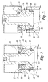
- the gas cylinder actuator according to the invention is shown in a second embodiment thereof in Figures 4 to 7 and designated therein by the reference numeral 110.
- the head portion 114 is formed by a sleeve 140, which is provided axially with a hole for the passage of the stem 115 with the piston 116.
- the sealing means 123 associated with the sleeve 140 are constituted by an inner sealing ring 141 for providing the dynamic seal with the stem 115 and by a static outer sealing ring 127, which is pressed against the inner face 122 of the jacket 111, as shown in Figure 4 and in the detail of Figure 5 .
- the sleeve 140 is coupled, in the fixing region 119, inside the jacket 111 by means of an extraction-preventing ring 143 that is interposed between two mutually opposite shoulders, a first shoulder 144, formed on the outside of the sleeve 140, and a second shoulder 145 on the inner face 122 of the jacket 111.
- the region in low relief 121 interrupts the seal provided by the gasket means 123 associated with the sleeve 140, or by the static sealing ring 127 that operates against the inner face 122 of the jacket 111, if the first shoulder 144 yields, as a consequence of a sudden overload (for example, an uncontrolled return stroke of the stem 15), and the sleeve 140, propelled outward by the gas, rises, bringing the static sealing ring 127 to the region in low relief 121, as shown in Figure 6 and in the detail of Figure 7 .
- the first shoulder 144 is provided in a cantilever fashion, providing a preferred yielding point.
- the sleeve 140 is provided with a third shoulder 146 having an outside diameter that is larger than the inside diameter of the extraction-preventing ring 143, designed to prevent the exit of the sleeve 140 from the jacket 11, obviously if the extraction-preventing ring 143 remains in its seat during the impact or malfunction in general.
- the region in low relief 121 is formed by recesses or by an annular slot that lies on a perimeter of the inner face 122.
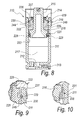
- the gas cylinder actuator according to the invention is illustrated in a third embodiment thereof in Figures 8 to 10 and designated therein by the reference numeral 210.
- the head portion 214 is formed by an annular gasket supporting body 225 and by a closure ring 226, to be screwed onto a corresponding threaded collar 227 of the annular body 225 so as to lock it.
- the annular body 225 is retained in the jacket 211 by a locking ring 229, which is inserted so as to protrude, at the fixing region 219, in an annular slot 230 formed on the inner face 222 of the jacket 211 proximately to the end portion 231 of the jacket.
- the ring 229 on the opposite side, is pressed into a perimetric hollow 233 formed in the annular body 225.
- the gasket means 223 are constituted, in this third embodiment, by a sealing ring 228 with a V-shaped lip, which is fitted on the piston 216 carried by the stem 215.
- the sealing ring 228 operates, during normal operation of the gas cylinder actuator 210, against the internal face 222 of the jacket 211.
- a first shoulder 244 is provided in a cantilever fashion at the perimetric hollow 233 formed in the annular body 225.
- a second shoulder 246, for limiting the stroke of the annular body 225, is formed below the first shoulder 244.
- the region in low relief 221 interrupts the seal provided by the gasket means 223 associated with the piston 216, or by the sealing ring 228, that operates against the inner face 222 of the jacket 211, if the first shoulder 244 yields, as exemplified in Figure 9 , and the annular body 225, pushed by the piston 216 in turn propelled by the gas, rises, bringing the sealing ring 228 to the region in low relief 221, as shown in Figure 10 .
- the first shoulder 244 is provided in a cantilever fashion, providing a preferred yielding point.
- the second shoulder 246 has an outside diameter that is larger than the inside diameter of the locking ring 229, and is designed to prevent the escape of the annular body 225 from the jacket 211.
- the region in low relief 221 is formed by recesses or by an annular slot that lies on a perimeter of the inner face 222.
- the present invention provides a gas cylinder actuator 10 and 110 which, thanks to the region in low relief 21 and 121, ensures the safe venting of the pressurized gas, avoiding any uncontrolled ejection of the stem 15 and 115 and of the piston 16, 116 and 216.
- the invention provides a gas cylinder actuator in which any overload in the compression and expansion chamber 17 and 117 never causes the uncontrolled ejection of the piston 16 and 116, because in case of impact due to uncontrolled rise the piston 16 and 116 and the stem 15 and 115 are designed to resist, while the portion 20 with reduced cross-section, as well as the first shoulder 144 of the sleeve 140, is such as to yield and allow the piston or sleeve to continue the stroke until its sealing means 23 and 123 meet the corresponding region in low relief 21 and 121, causing the discharge of the gas and the sudden decrease of the ejection speed of the stem with the piston.
- the invention provides a gas cylinder actuator whose performance is not inferior to that of similar gas cylinder actuators of the known type.
- the invention provides a gas cylinder actuator that is easy to install in machines and equipment of a known type without particular refinement.
- the invention provides a gas cylinder actuator with a safety device for controlled ejection of the piston stem that is structurally simple and can be manufactured at low cost with known systems and technologies.
- the materials used may be any according to requirements and to the state of the art.
Landscapes
- Engineering & Computer Science (AREA)
- General Engineering & Computer Science (AREA)
- Mechanical Engineering (AREA)
- Actuator (AREA)
- Fluid-Damping Devices (AREA)
Applications Claiming Priority (1)
| Application Number | Priority Date | Filing Date | Title |
|---|---|---|---|
| ITPD2009A000100A IT1393971B1 (it) | 2009-04-21 | 2009-04-21 | Molla a gas con dispositivo di sicurezza per l'eiezione controllata dello stelo pistone |
Publications (2)
| Publication Number | Publication Date |
|---|---|
| EP2243976A1 true EP2243976A1 (de) | 2010-10-27 |
| EP2243976B1 EP2243976B1 (de) | 2015-09-23 |
Family
ID=41228217
Family Applications (1)
| Application Number | Title | Priority Date | Filing Date |
|---|---|---|---|
| EP10160032.8A Active EP2243976B1 (de) | 2009-04-21 | 2010-04-15 | Gaszylinderaktuator mit Sicherheitsvorrichtung für kontrollierten Ausstoß der Kolbenstange |
Country Status (9)
| Country | Link |
|---|---|
| US (1) | US9157500B2 (de) |
| EP (1) | EP2243976B1 (de) |
| JP (1) | JP5480366B2 (de) |
| KR (1) | KR101663144B1 (de) |
| CN (1) | CN102405360B (de) |
| BR (1) | BRPI1013414B1 (de) |
| ES (1) | ES2557677T3 (de) |
| IT (1) | IT1393971B1 (de) |
| WO (1) | WO2010121946A1 (de) |
Cited By (4)
| Publication number | Priority date | Publication date | Assignee | Title |
|---|---|---|---|---|
| EP2778438A1 (de) | 2013-03-13 | 2014-09-17 | Airbus Helicopters | Verschluss eines Hydrauliksystems, Hydrauliksystem und Flugzeu |
| EP3061540A1 (de) * | 2015-02-27 | 2016-08-31 | Special Springs S.r.l. | Gasbetätigte befestigungsvorrichtung für stanzvorrichtungen und stanzvorrichtung mit solcher befestigungsvorrichtung |
| CN109312803A (zh) * | 2016-06-22 | 2019-02-05 | 斯特朗肖曼有限公司 | 有保护布置的活塞缸装置及保护活塞缸装置防止活塞缸装置过载或故障的方法 |
| EP3158215B1 (de) * | 2014-06-19 | 2019-02-06 | Strömsholmen AB | Gasfeder |
Families Citing this family (17)
| Publication number | Priority date | Publication date | Assignee | Title |
|---|---|---|---|---|
| EP2634451B1 (de) * | 2012-03-01 | 2018-05-23 | Special Springs S.r.l. | Gaszylinderaktuator mit Nachlaufschutzvorrichtung |
| CN103375455B (zh) * | 2012-04-24 | 2015-12-02 | 东莞市欣悦模具有限公司 | 一种推杆机构 |
| US9347510B2 (en) | 2013-03-15 | 2016-05-24 | Dadco, Inc. | Overtravel pressure relief for a gas spring |
| US9551394B2 (en) | 2013-03-15 | 2017-01-24 | Dadco, Inc. | Overtravel pressure relief for a gas spring |
| US9447834B2 (en) | 2013-09-19 | 2016-09-20 | Dadco, Inc. | Overtravel pressure relief for a gas spring |
| CN105276057B (zh) * | 2014-07-04 | 2019-12-17 | 宁波裕盛家居科技有限公司 | 一种气动阻尼缓冲器 |
| ITUB20159302A1 (it) * | 2015-12-21 | 2017-06-21 | Special Springs Srl | Molla a gas con dispositivo di sicurezza per ritorno incontrollato dello stelo-pistone |
| ITUB20159608A1 (it) | 2015-12-21 | 2017-06-21 | Special Springs Srl | Molla a gas con dispositivo di sicurezza extra-corsa |
| ES2638539B1 (es) * | 2016-04-18 | 2018-07-31 | Nitrogas Group, S.L. | Cilindro de gas |
| ITUA20164635A1 (it) * | 2016-06-24 | 2017-12-24 | Special Springs Srl | Molla a gas con dispositivo di sicurezza |
| US10113605B2 (en) * | 2016-09-29 | 2018-10-30 | Dadco, Inc. | Overtravel relief assembly for a gas spring |
| EP3364066B1 (de) | 2017-02-17 | 2020-06-24 | Special Springs S.r.l. | Gaszylinderaktuator mit sicherheitsvorrichtung zur unkontrollierten rückstellung des kolbenschafts |
| DE102017103925A1 (de) * | 2017-02-24 | 2018-08-30 | Thyssenkrupp Ag | Verschlusspaket, Schwingungsdämpfer und Verwendung eines Dichtungshalters |
| GB2566332B (en) * | 2017-09-12 | 2019-12-11 | Metrol Springs Ltd | Seal housing |
| US20210140510A1 (en) * | 2019-11-12 | 2021-05-13 | Joyson Safety Systems Acquisition Llc | Energy damping linear actuator |
| CA3131743A1 (en) | 2020-10-20 | 2022-04-20 | Special Springs S.R.L. | Gas-filled cylinder with overtravel safety device |
| WO2024194843A1 (en) * | 2023-03-22 | 2024-09-26 | Special Springs S.R.L. | Filling method a gas spring and machine implementing such method |
Citations (2)
| Publication number | Priority date | Publication date | Assignee | Title |
|---|---|---|---|---|
| EP0427468A1 (de) * | 1989-11-08 | 1991-05-15 | Bernard Joseph Wallis | Gasfeder |
| EP0496324A1 (de) * | 1991-01-21 | 1992-07-29 | Stabilus GmbH | Kolben- und Zylinder-Vorrichtung |
Family Cites Families (8)
| Publication number | Priority date | Publication date | Assignee | Title |
|---|---|---|---|---|
| JPH07158612A (ja) * | 1993-10-01 | 1995-06-20 | Ckd Corp | ロッドレスシリンダ |
| US6086059A (en) * | 1998-02-13 | 2000-07-11 | Strolsholmen Ab | Gas spring device |
| FR2778956B1 (fr) * | 1998-05-22 | 2000-08-04 | Orflam Ind | Ressort a gaz incorporant un organe de securite |
| US6199838B1 (en) * | 1998-10-27 | 2001-03-13 | Diebolt International, Inc. | Gas spring filler valve |
| AT414033B (de) * | 2001-01-09 | 2006-08-15 | Blum Gmbh Julius | Dämpfer, insbesondere für möbel |
| DE10325357B4 (de) * | 2003-06-05 | 2005-08-04 | Schuler Pressen Gmbh & Co. Kg | Pneumatische Krafterzeugungseinrichtung mit Sicherheitseinrichtung |
| JP2005291470A (ja) * | 2004-04-05 | 2005-10-20 | Nhk Spring Co Ltd | ガスクッション装置 |
| DE102004026356B4 (de) * | 2004-05-26 | 2008-07-31 | Stabilus Gmbh | Zugfederanordnung |
-
2009
- 2009-04-21 IT ITPD2009A000100A patent/IT1393971B1/it active
-
2010
- 2010-04-15 EP EP10160032.8A patent/EP2243976B1/de active Active
- 2010-04-15 KR KR1020117027390A patent/KR101663144B1/ko active IP Right Grant
- 2010-04-15 WO PCT/EP2010/054982 patent/WO2010121946A1/en active Application Filing
- 2010-04-15 BR BRPI1013414-0A patent/BRPI1013414B1/pt active IP Right Grant
- 2010-04-15 CN CN201080018139.9A patent/CN102405360B/zh active Active
- 2010-04-15 US US13/138,882 patent/US9157500B2/en active Active
- 2010-04-15 ES ES10160032.8T patent/ES2557677T3/es active Active
- 2010-04-15 JP JP2012506448A patent/JP5480366B2/ja active Active
Patent Citations (2)
| Publication number | Priority date | Publication date | Assignee | Title |
|---|---|---|---|---|
| EP0427468A1 (de) * | 1989-11-08 | 1991-05-15 | Bernard Joseph Wallis | Gasfeder |
| EP0496324A1 (de) * | 1991-01-21 | 1992-07-29 | Stabilus GmbH | Kolben- und Zylinder-Vorrichtung |
Cited By (8)
| Publication number | Priority date | Publication date | Assignee | Title |
|---|---|---|---|---|
| EP2778438A1 (de) | 2013-03-13 | 2014-09-17 | Airbus Helicopters | Verschluss eines Hydrauliksystems, Hydrauliksystem und Flugzeu |
| FR3003327A1 (fr) * | 2013-03-13 | 2014-09-19 | Eurocopter France | Dispositif d obturation d un systeme hydraulique systeme hydraulique et aeronef |
| EP3158215B1 (de) * | 2014-06-19 | 2019-02-06 | Strömsholmen AB | Gasfeder |
| EP3061540A1 (de) * | 2015-02-27 | 2016-08-31 | Special Springs S.r.l. | Gasbetätigte befestigungsvorrichtung für stanzvorrichtungen und stanzvorrichtung mit solcher befestigungsvorrichtung |
| KR20160105336A (ko) * | 2015-02-27 | 2016-09-06 | 스페셜 스프링스 에스.알.엘. | 펀칭 장치를 위한 가스 작동식 홀드 다운 및 이러한 홀드 다운을 갖는 펀칭 장치 |
| CN109312803A (zh) * | 2016-06-22 | 2019-02-05 | 斯特朗肖曼有限公司 | 有保护布置的活塞缸装置及保护活塞缸装置防止活塞缸装置过载或故障的方法 |
| US11226022B2 (en) | 2016-06-22 | 2022-01-18 | Stromsholmen Ab | Piston cylinder device with protection arrangement and method of protecting a piston cylinder device against overload or failure of the piston cylinder device |
| US11761504B2 (en) | 2016-06-22 | 2023-09-19 | Stromsholmen Ab | Piston cylinder device with protection arrangement and method of protecting a piston cylinder device against overload or failure of the piston cylinder device |
Also Published As
| Publication number | Publication date |
|---|---|
| CN102405360A (zh) | 2012-04-04 |
| WO2010121946A1 (en) | 2010-10-28 |
| BRPI1013414A2 (pt) | 2016-04-05 |
| IT1393971B1 (it) | 2012-05-17 |
| ITPD20090100A1 (it) | 2010-10-22 |
| EP2243976B1 (de) | 2015-09-23 |
| KR20120007053A (ko) | 2012-01-19 |
| CN102405360B (zh) | 2014-01-01 |
| BRPI1013414B1 (pt) | 2020-07-07 |
| JP2012524875A (ja) | 2012-10-18 |
| ES2557677T3 (es) | 2016-01-27 |
| US9157500B2 (en) | 2015-10-13 |
| US20120042770A1 (en) | 2012-02-23 |
| JP5480366B2 (ja) | 2014-04-23 |
| KR101663144B1 (ko) | 2016-10-06 |
Similar Documents
| Publication | Publication Date | Title |
|---|---|---|
| US9157500B2 (en) | Gas cylinder actuator with safety system for controlled ejection of the piston stem | |
| EP2406520B1 (de) | Gaszylinderaktuator mit überhubsicherheitsvorrichtung | |
| EP2634451B1 (de) | Gaszylinderaktuator mit Nachlaufschutzvorrichtung | |
| EP2980438B1 (de) | Gasbetriebene feder | |
| EP3364066B1 (de) | Gaszylinderaktuator mit sicherheitsvorrichtung zur unkontrollierten rückstellung des kolbenschafts | |
| EP3260726B1 (de) | Gaszylinderaktuator mit sicherheitsvorrichtung | |
| EP3184847B1 (de) | Gaszylinderaktuator mit sicherheitsvorrichtung | |
| US10907663B2 (en) | Gas cylinder actuator with overtravel indicator device | |
| EP3184848B1 (de) | Gaszylinderaktuator mit nachlaufschutzvorrichtung |
Legal Events
| Date | Code | Title | Description |
|---|---|---|---|
| PUAI | Public reference made under article 153(3) epc to a published international application that has entered the european phase |
Free format text: ORIGINAL CODE: 0009012 |
|
| AK | Designated contracting states |
Kind code of ref document: A1 Designated state(s): AT BE BG CH CY CZ DE DK EE ES FI FR GB GR HR HU IE IS IT LI LT LU LV MC MK MT NL NO PL PT RO SE SI SK SM TR |
|
| AX | Request for extension of the european patent |
Extension state: AL BA ME RS |
|
| 17P | Request for examination filed |
Effective date: 20110427 |
|
| 17Q | First examination report despatched |
Effective date: 20131002 |
|
| GRAP | Despatch of communication of intention to grant a patent |
Free format text: ORIGINAL CODE: EPIDOSNIGR1 |
|
| INTG | Intention to grant announced |
Effective date: 20150414 |
|
| RAP1 | Party data changed (applicant data changed or rights of an application transferred) |
Owner name: SPECIAL SPRINGS S.R.L. |
|
| GRAS | Grant fee paid |
Free format text: ORIGINAL CODE: EPIDOSNIGR3 |
|
| GRAA | (expected) grant |
Free format text: ORIGINAL CODE: 0009210 |
|
| AK | Designated contracting states |
Kind code of ref document: B1 Designated state(s): AT BE BG CH CY CZ DE DK EE ES FI FR GB GR HR HU IE IS IT LI LT LU LV MC MK MT NL NO PL PT RO SE SI SK SM TR |
|
| REG | Reference to a national code |
Ref country code: GB Ref legal event code: FG4D |
|
| REG | Reference to a national code |
Ref country code: CH Ref legal event code: EP |
|
| REG | Reference to a national code |
Ref country code: AT Ref legal event code: REF Ref document number: 751434 Country of ref document: AT Kind code of ref document: T Effective date: 20151015 |
|
| REG | Reference to a national code |
Ref country code: IE Ref legal event code: FG4D |
|
| REG | Reference to a national code |
Ref country code: DE Ref legal event code: R096 Ref document number: 602010027677 Country of ref document: DE |
|
| REG | Reference to a national code |
Ref country code: SE Ref legal event code: TRGR |
|
| REG | Reference to a national code |
Ref country code: ES Ref legal event code: FG2A Ref document number: 2557677 Country of ref document: ES Kind code of ref document: T3 Effective date: 20160127 Ref country code: NL Ref legal event code: MP Effective date: 20150923 |
|
| PG25 | Lapsed in a contracting state [announced via postgrant information from national office to epo] |
Ref country code: LV Free format text: LAPSE BECAUSE OF FAILURE TO SUBMIT A TRANSLATION OF THE DESCRIPTION OR TO PAY THE FEE WITHIN THE PRESCRIBED TIME-LIMIT Effective date: 20150923 Ref country code: LT Free format text: LAPSE BECAUSE OF FAILURE TO SUBMIT A TRANSLATION OF THE DESCRIPTION OR TO PAY THE FEE WITHIN THE PRESCRIBED TIME-LIMIT Effective date: 20150923 Ref country code: FI Free format text: LAPSE BECAUSE OF FAILURE TO SUBMIT A TRANSLATION OF THE DESCRIPTION OR TO PAY THE FEE WITHIN THE PRESCRIBED TIME-LIMIT Effective date: 20150923 Ref country code: NO Free format text: LAPSE BECAUSE OF FAILURE TO SUBMIT A TRANSLATION OF THE DESCRIPTION OR TO PAY THE FEE WITHIN THE PRESCRIBED TIME-LIMIT Effective date: 20151223 Ref country code: GR Free format text: LAPSE BECAUSE OF FAILURE TO SUBMIT A TRANSLATION OF THE DESCRIPTION OR TO PAY THE FEE WITHIN THE PRESCRIBED TIME-LIMIT Effective date: 20151224 |
|
| REG | Reference to a national code |
Ref country code: LT Ref legal event code: MG4D |
|
| REG | Reference to a national code |
Ref country code: AT Ref legal event code: MK05 Ref document number: 751434 Country of ref document: AT Kind code of ref document: T Effective date: 20150923 |
|
| PG25 | Lapsed in a contracting state [announced via postgrant information from national office to epo] |
Ref country code: HR Free format text: LAPSE BECAUSE OF FAILURE TO SUBMIT A TRANSLATION OF THE DESCRIPTION OR TO PAY THE FEE WITHIN THE PRESCRIBED TIME-LIMIT Effective date: 20150923 |
|
| REG | Reference to a national code |
Ref country code: FR Ref legal event code: PLFP Year of fee payment: 7 |
|
| PG25 | Lapsed in a contracting state [announced via postgrant information from national office to epo] |
Ref country code: NL Free format text: LAPSE BECAUSE OF FAILURE TO SUBMIT A TRANSLATION OF THE DESCRIPTION OR TO PAY THE FEE WITHIN THE PRESCRIBED TIME-LIMIT Effective date: 20150923 |
|
| PG25 | Lapsed in a contracting state [announced via postgrant information from national office to epo] |
Ref country code: IS Free format text: LAPSE BECAUSE OF FAILURE TO SUBMIT A TRANSLATION OF THE DESCRIPTION OR TO PAY THE FEE WITHIN THE PRESCRIBED TIME-LIMIT Effective date: 20160123 Ref country code: CZ Free format text: LAPSE BECAUSE OF FAILURE TO SUBMIT A TRANSLATION OF THE DESCRIPTION OR TO PAY THE FEE WITHIN THE PRESCRIBED TIME-LIMIT Effective date: 20150923 Ref country code: EE Free format text: LAPSE BECAUSE OF FAILURE TO SUBMIT A TRANSLATION OF THE DESCRIPTION OR TO PAY THE FEE WITHIN THE PRESCRIBED TIME-LIMIT Effective date: 20150923 Ref country code: SK Free format text: LAPSE BECAUSE OF FAILURE TO SUBMIT A TRANSLATION OF THE DESCRIPTION OR TO PAY THE FEE WITHIN THE PRESCRIBED TIME-LIMIT Effective date: 20150923 |
|
| PG25 | Lapsed in a contracting state [announced via postgrant information from national office to epo] |
Ref country code: AT Free format text: LAPSE BECAUSE OF FAILURE TO SUBMIT A TRANSLATION OF THE DESCRIPTION OR TO PAY THE FEE WITHIN THE PRESCRIBED TIME-LIMIT Effective date: 20150923 Ref country code: PT Free format text: LAPSE BECAUSE OF FAILURE TO SUBMIT A TRANSLATION OF THE DESCRIPTION OR TO PAY THE FEE WITHIN THE PRESCRIBED TIME-LIMIT Effective date: 20160125 Ref country code: RO Free format text: LAPSE BECAUSE OF FAILURE TO SUBMIT A TRANSLATION OF THE DESCRIPTION OR TO PAY THE FEE WITHIN THE PRESCRIBED TIME-LIMIT Effective date: 20150923 Ref country code: PL Free format text: LAPSE BECAUSE OF FAILURE TO SUBMIT A TRANSLATION OF THE DESCRIPTION OR TO PAY THE FEE WITHIN THE PRESCRIBED TIME-LIMIT Effective date: 20150923 |
|
| REG | Reference to a national code |
Ref country code: DE Ref legal event code: R097 Ref document number: 602010027677 Country of ref document: DE |
|
| PLBE | No opposition filed within time limit |
Free format text: ORIGINAL CODE: 0009261 |
|
| STAA | Information on the status of an ep patent application or granted ep patent |
Free format text: STATUS: NO OPPOSITION FILED WITHIN TIME LIMIT |
|
| 26N | No opposition filed |
Effective date: 20160624 |
|
| PG25 | Lapsed in a contracting state [announced via postgrant information from national office to epo] |
Ref country code: DK Free format text: LAPSE BECAUSE OF FAILURE TO SUBMIT A TRANSLATION OF THE DESCRIPTION OR TO PAY THE FEE WITHIN THE PRESCRIBED TIME-LIMIT Effective date: 20150923 Ref country code: BE Free format text: LAPSE BECAUSE OF NON-PAYMENT OF DUE FEES Effective date: 20160430 |
|
| PG25 | Lapsed in a contracting state [announced via postgrant information from national office to epo] |
Ref country code: SI Free format text: LAPSE BECAUSE OF FAILURE TO SUBMIT A TRANSLATION OF THE DESCRIPTION OR TO PAY THE FEE WITHIN THE PRESCRIBED TIME-LIMIT Effective date: 20150923 |
|
| REG | Reference to a national code |
Ref country code: CH Ref legal event code: PL |
|
| PG25 | Lapsed in a contracting state [announced via postgrant information from national office to epo] |
Ref country code: BE Free format text: LAPSE BECAUSE OF FAILURE TO SUBMIT A TRANSLATION OF THE DESCRIPTION OR TO PAY THE FEE WITHIN THE PRESCRIBED TIME-LIMIT Effective date: 20150923 Ref country code: LU Free format text: LAPSE BECAUSE OF FAILURE TO SUBMIT A TRANSLATION OF THE DESCRIPTION OR TO PAY THE FEE WITHIN THE PRESCRIBED TIME-LIMIT Effective date: 20160415 |
|
| REG | Reference to a national code |
Ref country code: IE Ref legal event code: MM4A |
|
| PG25 | Lapsed in a contracting state [announced via postgrant information from national office to epo] |
Ref country code: CH Free format text: LAPSE BECAUSE OF NON-PAYMENT OF DUE FEES Effective date: 20160430 Ref country code: LI Free format text: LAPSE BECAUSE OF NON-PAYMENT OF DUE FEES Effective date: 20160430 |
|
| REG | Reference to a national code |
Ref country code: FR Ref legal event code: PLFP Year of fee payment: 8 |
|
| PG25 | Lapsed in a contracting state [announced via postgrant information from national office to epo] |
Ref country code: IE Free format text: LAPSE BECAUSE OF NON-PAYMENT OF DUE FEES Effective date: 20160415 |
|
| REG | Reference to a national code |
Ref country code: FR Ref legal event code: PLFP Year of fee payment: 9 |
|
| PG25 | Lapsed in a contracting state [announced via postgrant information from national office to epo] |
Ref country code: CY Free format text: LAPSE BECAUSE OF FAILURE TO SUBMIT A TRANSLATION OF THE DESCRIPTION OR TO PAY THE FEE WITHIN THE PRESCRIBED TIME-LIMIT Effective date: 20150923 Ref country code: SM Free format text: LAPSE BECAUSE OF FAILURE TO SUBMIT A TRANSLATION OF THE DESCRIPTION OR TO PAY THE FEE WITHIN THE PRESCRIBED TIME-LIMIT Effective date: 20150923 Ref country code: HU Free format text: LAPSE BECAUSE OF FAILURE TO SUBMIT A TRANSLATION OF THE DESCRIPTION OR TO PAY THE FEE WITHIN THE PRESCRIBED TIME-LIMIT; INVALID AB INITIO Effective date: 20100415 |
|
| PG25 | Lapsed in a contracting state [announced via postgrant information from national office to epo] |
Ref country code: MC Free format text: LAPSE BECAUSE OF FAILURE TO SUBMIT A TRANSLATION OF THE DESCRIPTION OR TO PAY THE FEE WITHIN THE PRESCRIBED TIME-LIMIT Effective date: 20150923 Ref country code: MT Free format text: LAPSE BECAUSE OF NON-PAYMENT OF DUE FEES Effective date: 20160430 Ref country code: MK Free format text: LAPSE BECAUSE OF FAILURE TO SUBMIT A TRANSLATION OF THE DESCRIPTION OR TO PAY THE FEE WITHIN THE PRESCRIBED TIME-LIMIT Effective date: 20150923 |
|
| PG25 | Lapsed in a contracting state [announced via postgrant information from national office to epo] |
Ref country code: BG Free format text: LAPSE BECAUSE OF FAILURE TO SUBMIT A TRANSLATION OF THE DESCRIPTION OR TO PAY THE FEE WITHIN THE PRESCRIBED TIME-LIMIT Effective date: 20150923 |
|
| P01 | Opt-out of the competence of the unified patent court (upc) registered |
Effective date: 20230529 |
|
| PGFP | Annual fee paid to national office [announced via postgrant information from national office to epo] |
Ref country code: GB Payment date: 20240320 Year of fee payment: 15 |
|
| PGFP | Annual fee paid to national office [announced via postgrant information from national office to epo] |
Ref country code: FR Payment date: 20240327 Year of fee payment: 15 |
|
| PGFP | Annual fee paid to national office [announced via postgrant information from national office to epo] |
Ref country code: DE Payment date: 20240419 Year of fee payment: 15 |
|
| PGFP | Annual fee paid to national office [announced via postgrant information from national office to epo] |
Ref country code: ES Payment date: 20240508 Year of fee payment: 15 |
|
| PGFP | Annual fee paid to national office [announced via postgrant information from national office to epo] |
Ref country code: IT Payment date: 20240422 Year of fee payment: 15 |
|
| PGFP | Annual fee paid to national office [announced via postgrant information from national office to epo] |
Ref country code: TR Payment date: 20240404 Year of fee payment: 15 Ref country code: SE Payment date: 20240416 Year of fee payment: 15 |