EP2243910A2 - Einsteckverriegelung mit Rollfalle - Google Patents
Einsteckverriegelung mit Rollfalle Download PDFInfo
- Publication number
- EP2243910A2 EP2243910A2 EP09460045A EP09460045A EP2243910A2 EP 2243910 A2 EP2243910 A2 EP 2243910A2 EP 09460045 A EP09460045 A EP 09460045A EP 09460045 A EP09460045 A EP 09460045A EP 2243910 A2 EP2243910 A2 EP 2243910A2
- Authority
- EP
- European Patent Office
- Prior art keywords
- roller
- lock
- cutout
- face plate
- axis
- Prior art date
- Legal status (The legal status is an assumption and is not a legal conclusion. Google has not performed a legal analysis and makes no representation as to the accuracy of the status listed.)
- Withdrawn
Links
- 239000012634 fragment Substances 0.000 claims abstract description 20
- 239000007787 solid Substances 0.000 claims abstract 3
- 239000002184 metal Substances 0.000 claims description 6
- 238000009434 installation Methods 0.000 description 3
- 238000000034 method Methods 0.000 description 3
- 230000010354 integration Effects 0.000 description 2
- 229910001220 stainless steel Inorganic materials 0.000 description 2
- 239000010935 stainless steel Substances 0.000 description 2
- 238000005266 casting Methods 0.000 description 1
- 238000010276 construction Methods 0.000 description 1
- 230000006735 deficit Effects 0.000 description 1
- 238000005553 drilling Methods 0.000 description 1
- 230000002349 favourable effect Effects 0.000 description 1
- 239000000463 material Substances 0.000 description 1
- 230000008439 repair process Effects 0.000 description 1
- 238000007493 shaping process Methods 0.000 description 1
Images

Classifications
-
- E—FIXED CONSTRUCTIONS
- E05—LOCKS; KEYS; WINDOW OR DOOR FITTINGS; SAFES
- E05C—BOLTS OR FASTENING DEVICES FOR WINGS, SPECIALLY FOR DOORS OR WINDOWS
- E05C19/00—Other devices specially designed for securing wings, e.g. with suction cups
- E05C19/02—Automatic catches, i.e. released by pull or pressure on the wing
- E05C19/04—Ball or roller catches
-
- E—FIXED CONSTRUCTIONS
- E05—LOCKS; KEYS; WINDOW OR DOOR FITTINGS; SAFES
- E05B—LOCKS; ACCESSORIES THEREFOR; HANDCUFFS
- E05B63/00—Locks or fastenings with special structural characteristics
- E05B63/06—Locks or fastenings with special structural characteristics with lengthwise-adjustable bolts ; with adjustable backset, i.e. distance from door edge
-
- E—FIXED CONSTRUCTIONS
- E05—LOCKS; KEYS; WINDOW OR DOOR FITTINGS; SAFES
- E05B—LOCKS; ACCESSORIES THEREFOR; HANDCUFFS
- E05B15/00—Other details of locks; Parts for engagement by bolts of fastening devices
- E05B15/10—Bolts of locks or night latches
- E05B15/102—Bolts having movable elements
Definitions
- a subject matter of the present invention is a mortise roller lock particularly applied in the furniture doors and in joinery as well as incorporating a roller with rotable fastening on a slide block performing to - and - fro movement; being under the influence of spring and incorporating a mechanism for non-loaded roller position adjustment.
- roller locks are generally known, particularly those applied for the doors. Said roller locks are usually mounted in the recesses provided in the doors or door frames.
- the lock consists of the lock box constituting the enclosure of the roller mechanism, usually consisting of the roller, slide block of the roller and rivet or bolt constituting the rotation axis of roller as well as of the mechanism for non-loaded roller position adjustment and spring.
- the adjustment mechanism always incorporates an adjustment screw and bearing surface directly or indirectly supporting the slide block of the roller.
- the lock box usually consists of two metal sheets characterized by proper shape and screwed or riveted together.
- the face plate of the lock is fastened onto one of said metal sheets constituting the lock box elements.
- Said face plate of the lock is screwed or riveted to the lock box element in known solutions.
- face plate and lock box of the lock casted in the form of an integral element or in the form of two elements with one of said elements used for screwing of lock box cover.
- the mechanism for non-loaded roller position adjustment applied in known solutions incorporates the adjustment screw with the axis perpendicular to the face plate of the lock and always located on the plane passing through the roller axis and perpendicular to the face plate of the lock.
- the axis of the adjustment screw is located under the roll when looking at the lock mounted in the door.
- the aim of the invention is to elaborate the construction of a mortise roller lock to be mounted in a cylindrical recess i.e. which can be prepared by means of a drilling tool. Therefore the installation will be simple. Owing to the width of the door said lock shall be extremely compact with the diameter ensuring its correct functioning. Furthermore said lock shall provide the option in the form of the face plate made of stainless steel sheet.
- the aim of the invention has been accomplished in the mortise roller lock solution pursuant to the invention, incorporating the roller with rotable fastening on the slide block performing to - and - fro movement in course of the lock operation; being under the influence of spring with one end supported on the bottom of the box and another end on the latter wall of the slider block and incorporating the mechanism for non-loaded roller position adjustment.
- the distinctive feature of the mortise roller lock solution pursuant to the invention is the fact that the axis of adjustment screw intersects the face plate of the lock in the proximity of a clearance between the central part of the rotating surface of the roller and opening for the roller provided on the face surface of the lock.
- a cutout has been provided in the roller on the level of said axis and opening for the roller in the face plate has been enlarged i.e. provided with similar cutouts, favourably consisting a fragment of circle, enlargements of opening.
- the cutout on the roller has not to be provided on the whole circumference of the roller.
- the purpose of said cutout and enlargement of opening for the roller is to enable the inserting of adjustment tool into the adjustment screw.
- the advantage of this solution consists in space saving.
- the adjustment provisions and roller are contained in cylinder with adequate diameter, maintaining sufficiently large diameter of the roller and correct bearings system of the roller.
- Another distinctive feature of the lock pursuant to the invention is the method of the connection of the lock face plate made of metal sheet. Two fragments of this plate have been bent from a part of metal sheet behind the opening for the roller, while said fragments in the part more distant from the face surface of the lock are wider than those in the part closer to the face surface of the lock, and the lock box consisting of at least two elements, is characterized by favourably shaped seat in the form of bent fragments of the face surface of the lock, while the bent fragments of the face surface of the lock are locked by said elements of the lock box after final assembling of the lock.
- the shaping of bent fragments of the lock in the form of "T' letter is favourable.
- Another distinctive feature of the lock pursuant to the invention is the method of the integration of individual elements of the lock box together. It is accomplished by means of a round sleeve to be slided over onto the lock box elements. In order to prevent any unintended sliding the sleeve off the box, a fragment said sleeve is crimped on the box after its positioning in proper position.
- Fig. 1 illustrates the front view of the roller lock pursuant to the invention
- Fig. 2 illustrates the longitudinal section along the line B-B of the roller lock set up behind the line in top view
- Fig. 3 illustrates the longitudinal section of the roller lock C-C in side view
- Fig. 4 illustrates the lock roller in the variants in half section in top view
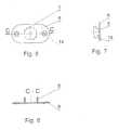
- Fig. 5 illustrates the face plate in front view
- Fig. 6 illustrates the section of the same face plate in top view
- Fig. 7 illustrates the plate of the lock in side view
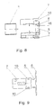
- Fig. 8 illustrates detached lock box consisting of two parts with adhering face plate of the lock and with sleeve closing the lock
- Fig. 8 illustrates the lock box with the face plate of the lock in top view.
Landscapes
- Engineering & Computer Science (AREA)
- Structural Engineering (AREA)
- Mechanical Engineering (AREA)
- Connection Of Plates (AREA)
- Soil Working Implements (AREA)
- Valve-Gear Or Valve Arrangements (AREA)
- Ticket-Dispensing Machines (AREA)
- Clamps And Clips (AREA)
- Support Devices For Sliding Doors (AREA)
Applications Claiming Priority (1)
| Application Number | Priority Date | Filing Date | Title |
|---|---|---|---|
| PL387841A PL219617B1 (pl) | 2009-04-20 | 2009-04-20 | Zamek rolkowy wpuszczany |
Publications (2)
| Publication Number | Publication Date |
|---|---|
| EP2243910A2 true EP2243910A2 (de) | 2010-10-27 |
| EP2243910A3 EP2243910A3 (de) | 2011-05-18 |
Family
ID=42557012
Family Applications (1)
| Application Number | Title | Priority Date | Filing Date |
|---|---|---|---|
| EP09460045A Withdrawn EP2243910A3 (de) | 2009-04-20 | 2009-10-16 | Einsteckverriegelung mit Rollfalle |
Country Status (2)
| Country | Link |
|---|---|
| EP (1) | EP2243910A3 (de) |
| PL (1) | PL219617B1 (de) |
Cited By (1)
| Publication number | Priority date | Publication date | Assignee | Title |
|---|---|---|---|---|
| GB2588428A (en) * | 2019-10-23 | 2021-04-28 | Era Home Security Ltd | Locking assembly |
Citations (4)
| Publication number | Priority date | Publication date | Assignee | Title |
|---|---|---|---|---|
| DE1678159A1 (de) | 1967-03-29 | 1971-06-09 | Gust Kuhs Fa | Rollenschnaepper |
| DE4218733A1 (de) | 1992-06-06 | 1993-12-09 | Fuhr Carl Gmbh & Co | Falle, insbesondere an Treibstangenbeschlägen |
| EP0785321B1 (de) | 1996-01-19 | 2003-04-16 | Roto Frank Eisenwarenfabrik Aktiengesellschaft | Rollfalle mit einem Rollfallenschaft |
| FR2844820A1 (fr) | 2002-09-21 | 2004-03-26 | Fuhr Carl Gmbh & Co Kg | Serrure a tiges de commande |
Family Cites Families (3)
| Publication number | Priority date | Publication date | Assignee | Title |
|---|---|---|---|---|
| DE1055395B (de) * | 1954-07-15 | 1959-04-16 | Smith And Davis Ltd | Federnde, mit einem Schliessblech zusammenwirkende Falle |
| GB875650A (en) * | 1959-02-19 | 1961-08-23 | Tonks Birmingham Ltd | Latch bolts |
| GB979038A (en) * | 1963-03-19 | 1965-01-01 | Jones | Improvements in or relating to door catches |
-
2009
- 2009-04-20 PL PL387841A patent/PL219617B1/pl unknown
- 2009-10-16 EP EP09460045A patent/EP2243910A3/de not_active Withdrawn
Patent Citations (4)
| Publication number | Priority date | Publication date | Assignee | Title |
|---|---|---|---|---|
| DE1678159A1 (de) | 1967-03-29 | 1971-06-09 | Gust Kuhs Fa | Rollenschnaepper |
| DE4218733A1 (de) | 1992-06-06 | 1993-12-09 | Fuhr Carl Gmbh & Co | Falle, insbesondere an Treibstangenbeschlägen |
| EP0785321B1 (de) | 1996-01-19 | 2003-04-16 | Roto Frank Eisenwarenfabrik Aktiengesellschaft | Rollfalle mit einem Rollfallenschaft |
| FR2844820A1 (fr) | 2002-09-21 | 2004-03-26 | Fuhr Carl Gmbh & Co Kg | Serrure a tiges de commande |
Cited By (4)
| Publication number | Priority date | Publication date | Assignee | Title |
|---|---|---|---|---|
| GB2588428A (en) * | 2019-10-23 | 2021-04-28 | Era Home Security Ltd | Locking assembly |
| IE20200231A3 (en) * | 2019-10-23 | 2021-04-28 | Era Home Security Ltd | Locking assembly |
| GB2588428B (en) * | 2019-10-23 | 2024-05-15 | Era Home Security Ltd | Locking assembly |
| IE87572B1 (en) * | 2019-10-23 | 2025-01-01 | Era Home Security Limited | Locking assembly |
Also Published As
| Publication number | Publication date |
|---|---|
| PL219617B1 (pl) | 2015-06-30 |
| EP2243910A3 (de) | 2011-05-18 |
| PL387841A1 (pl) | 2010-10-25 |
Similar Documents
| Publication | Publication Date | Title |
|---|---|---|
| US9145721B2 (en) | Door hinge | |
| US8336349B2 (en) | Lock assembly | |
| US8413299B2 (en) | Hinge for door or window | |
| CN114382341A (zh) | 无装饰盖门窗把手 | |
| AU3347001A (en) | Quick release door for a vending machine | |
| EP2243910A2 (de) | Einsteckverriegelung mit Rollfalle | |
| CA2941596C (en) | Adjustable hinge for vertically hanging panel | |
| RU2509854C2 (ru) | Замковое устройство полотна пассивной двери двупольной двери | |
| EP2927407B1 (de) | Scharnier | |
| CN201170011Y (zh) | 松紧式合页 | |
| NO316789B1 (no) | Sikret hengsel, fortrinnsvis for vinduer og dorer | |
| KR20160115362A (ko) | 슬라이딩 도어 | |
| EP1713992B1 (de) | Anordnung zur befestigung einer schaltsteuerwelle an einer schaltrohrwelle | |
| ES2684991T5 (es) | Herraje con zona de sujeción ajustable | |
| EP2530224A2 (de) | Manipulationssicheres Schloss | |
| CN219012290U (zh) | 可调节明铰链 | |
| KR20170104250A (ko) | 방화문 힌지 | |
| GB2476486A (en) | A block member for locating on the shaft of a locking pin of a multipoint lock | |
| ITBS20090168A1 (it) | Dispositivo di interconnessione meccanica con un elemento cavo | |
| EP4692494A1 (de) | Nachtverriegelungsanordnung | |
| CN218991193U (zh) | 活动锁鼻结构以及门锁组件 | |
| CN204876835U (zh) | 一种可调节锁具挡片 | |
| JP4299097B2 (ja) | ゲーム機の施錠装置 | |
| JPH09137662A (ja) | 蝶番および蝶番装置 | |
| WO2005103420A1 (en) | Face plate assembly for door latch or lock |
Legal Events
| Date | Code | Title | Description |
|---|---|---|---|
| PUAI | Public reference made under article 153(3) epc to a published international application that has entered the european phase |
Free format text: ORIGINAL CODE: 0009012 |
|
| AK | Designated contracting states |
Kind code of ref document: A2 Designated state(s): AT BE BG CH CY CZ DE DK EE ES FI FR GB GR HR HU IE IS IT LI LT LU LV MC MK MT NL NO PL PT RO SE SI SK SM TR |
|
| AX | Request for extension of the european patent |
Extension state: AL BA RS |
|
| PUAL | Search report despatched |
Free format text: ORIGINAL CODE: 0009013 |
|
| AK | Designated contracting states |
Kind code of ref document: A3 Designated state(s): AT BE BG CH CY CZ DE DK EE ES FI FR GB GR HR HU IE IS IT LI LT LU LV MC MK MT NL NO PL PT RO SE SI SK SM TR |
|
| AX | Request for extension of the european patent |
Extension state: AL BA RS |
|
| 17P | Request for examination filed |
Effective date: 20111109 |
|
| RAP1 | Party data changed (applicant data changed or rights of an application transferred) |
Owner name: GAWRON, WOJCIECH |
|
| RIN1 | Information on inventor provided before grant (corrected) |
Inventor name: GAWRON, WOJCIECH |
|
| 17Q | First examination report despatched |
Effective date: 20130409 |
|
| GRAP | Despatch of communication of intention to grant a patent |
Free format text: ORIGINAL CODE: EPIDOSNIGR1 |
|
| INTG | Intention to grant announced |
Effective date: 20141008 |
|
| STAA | Information on the status of an ep patent application or granted ep patent |
Free format text: STATUS: THE APPLICATION IS DEEMED TO BE WITHDRAWN |
|
| 18D | Application deemed to be withdrawn |
Effective date: 20150219 |