EP2242912B1 - Variabler ventilbetätigungsmechanismus mit hebedeaktivierung - Google Patents
Variabler ventilbetätigungsmechanismus mit hebedeaktivierung Download PDFInfo
- Publication number
- EP2242912B1 EP2242912B1 EP08871486A EP08871486A EP2242912B1 EP 2242912 B1 EP2242912 B1 EP 2242912B1 EP 08871486 A EP08871486 A EP 08871486A EP 08871486 A EP08871486 A EP 08871486A EP 2242912 B1 EP2242912 B1 EP 2242912B1
- Authority
- EP
- European Patent Office
- Prior art keywords
- summation lever
- valve
- internal combustion
- combustion engine
- lever
- Prior art date
- Legal status (The legal status is an assumption and is not a legal conclusion. Google has not performed a legal analysis and makes no representation as to the accuracy of the status listed.)
- Not-in-force
Links
- 230000007246 mechanism Effects 0.000 title claims description 38
- 230000009849 deactivation Effects 0.000 title claims description 25
- 230000033001 locomotion Effects 0.000 claims description 30
- 238000002485 combustion reaction Methods 0.000 claims description 18
- 230000009471 action Effects 0.000 description 4
- 238000005553 drilling Methods 0.000 description 3
- 230000006870 function Effects 0.000 description 3
- 230000004913 activation Effects 0.000 description 2
- 230000000994 depressogenic effect Effects 0.000 description 2
- 238000000034 method Methods 0.000 description 2
- 230000008901 benefit Effects 0.000 description 1
- 230000005540 biological transmission Effects 0.000 description 1
- 230000008859 change Effects 0.000 description 1
- 230000008878 coupling Effects 0.000 description 1
- 238000010168 coupling process Methods 0.000 description 1
- 238000005859 coupling reaction Methods 0.000 description 1
- 230000006872 improvement Effects 0.000 description 1
- 238000004806 packaging method and process Methods 0.000 description 1
- 230000000717 retained effect Effects 0.000 description 1
- 230000001360 synchronised effect Effects 0.000 description 1
- 230000007704 transition Effects 0.000 description 1
- 238000013022 venting Methods 0.000 description 1
Images


Classifications
-
- F—MECHANICAL ENGINEERING; LIGHTING; HEATING; WEAPONS; BLASTING
- F01—MACHINES OR ENGINES IN GENERAL; ENGINE PLANTS IN GENERAL; STEAM ENGINES
- F01L—CYCLICALLY OPERATING VALVES FOR MACHINES OR ENGINES
- F01L13/00—Modifications of valve-gear to facilitate reversing, braking, starting, changing compression ratio, or other specific operations
- F01L13/0015—Modifications of valve-gear to facilitate reversing, braking, starting, changing compression ratio, or other specific operations for optimising engine performances by modifying valve lift according to various working parameters, e.g. rotational speed, load, torque
- F01L13/0036—Modifications of valve-gear to facilitate reversing, braking, starting, changing compression ratio, or other specific operations for optimising engine performances by modifying valve lift according to various working parameters, e.g. rotational speed, load, torque the valves being driven by two or more cams with different shape, size or timing or a single cam profiled in axial and radial direction
- F01L13/0047—Modifications of valve-gear to facilitate reversing, braking, starting, changing compression ratio, or other specific operations for optimising engine performances by modifying valve lift according to various working parameters, e.g. rotational speed, load, torque the valves being driven by two or more cams with different shape, size or timing or a single cam profiled in axial and radial direction the movement of the valves resulting from the sum of the simultaneous actions of at least two cams, the cams being independently variable in phase in respect of each other
-
- F—MECHANICAL ENGINEERING; LIGHTING; HEATING; WEAPONS; BLASTING
- F01—MACHINES OR ENGINES IN GENERAL; ENGINE PLANTS IN GENERAL; STEAM ENGINES
- F01L—CYCLICALLY OPERATING VALVES FOR MACHINES OR ENGINES
- F01L1/00—Valve-gear or valve arrangements, e.g. lift-valve gear
- F01L1/12—Transmitting gear between valve drive and valve
- F01L1/18—Rocking arms or levers
-
- F—MECHANICAL ENGINEERING; LIGHTING; HEATING; WEAPONS; BLASTING
- F01—MACHINES OR ENGINES IN GENERAL; ENGINE PLANTS IN GENERAL; STEAM ENGINES
- F01L—CYCLICALLY OPERATING VALVES FOR MACHINES OR ENGINES
- F01L1/00—Valve-gear or valve arrangements, e.g. lift-valve gear
- F01L1/26—Valve-gear or valve arrangements, e.g. lift-valve gear characterised by the provision of two or more valves operated simultaneously by same transmitting-gear; peculiar to machines or engines with more than two lift-valves per cylinder
- F01L1/267—Valve-gear or valve arrangements, e.g. lift-valve gear characterised by the provision of two or more valves operated simultaneously by same transmitting-gear; peculiar to machines or engines with more than two lift-valves per cylinder with means for varying the timing or the lift of the valves
-
- F—MECHANICAL ENGINEERING; LIGHTING; HEATING; WEAPONS; BLASTING
- F01—MACHINES OR ENGINES IN GENERAL; ENGINE PLANTS IN GENERAL; STEAM ENGINES
- F01L—CYCLICALLY OPERATING VALVES FOR MACHINES OR ENGINES
- F01L13/00—Modifications of valve-gear to facilitate reversing, braking, starting, changing compression ratio, or other specific operations
- F01L13/0005—Deactivating valves
-
- F—MECHANICAL ENGINEERING; LIGHTING; HEATING; WEAPONS; BLASTING
- F01—MACHINES OR ENGINES IN GENERAL; ENGINE PLANTS IN GENERAL; STEAM ENGINES
- F01L—CYCLICALLY OPERATING VALVES FOR MACHINES OR ENGINES
- F01L2305/00—Valve arrangements comprising rollers
Definitions
- the invention relates to an internal combustion engine having a valve actuating mechanism that comprises two cams mounted coaxially, a summation lever having at least one cam follower in contact with each respective cam and movable in proportion to the instantaneous sum of the lifts of the two cams, a control spring acting to maintain one cam in contact with each follower associated therewith, and a valve actuating rocker serving to open an engine valve in dependence upon the movement of the summation lever, the timing, lift and duration of each valve event being adjustable by varying the phases of the two cams.
- Figure 1a is a perspective view of a valve actuating mechanism as described in the latter patent application and Figure 1b is a section through the same mechanism.
- a poppet valve 10 is urged towards its closed position against its valve seat in the engine cylinder head by a valve spring 12.
- a downwards force to open the valve 10 is applied by an actuating rocker 14 of which the opposite end is pivoted on an adjustable articulated link 16.
- Valve actuation is effected by a camshaft driven in synchronism with the engine crankshaft which carries two cams 20 and 22 that can be phase shifted in relation to one another.
- the cam 20 is formed from two identical parts that straddle the other cam 22.
- a summation lever 24, which is pivotably carried by the actuating rocker 14 has roller followers 26, 27 at its opposite ends one of which is maintained in contact with a respective one of the two cams 20 and 22 by a control spring 28.
- the control spring 28 is required in a cam summation system of this type in order to control the motion of the summation lever 24 and to maintain contact between the actuating rocker 14 and the valve tip whilst the valve is closed. It can be seen from Figure 1b that the control spring 28 acts in a downward direction to force the adjacent cam follower 26 away from its cam lobe 22, and this forces the two followers 27 on the opposite side of the summation lever into contact with their respective cam lobes 20.
- the present invention seeks to provide an improvement of the valve actuating mechanism described above which additionally enables the valve 10 to be deactivated.
- valve deactivation system requires a lost motion spring to control the position of the valve train system and maintain contact between each cam lobe and its follower during the cam lift event when it is being operated with the valve deactivated.
- WO03/016684 is silent on how such a spring is incorporated in the valve deactivation system.
- an internal combustion engine having a valve mechanism that comprises two cams mounted coaxially, a summation lever having cam followers in contact with both cams, the summation lever being moveable in proportion to the instantaneous sum of the lifts of the respective cams, a control spring to maintain contact between one cam profile and its respective follower(s), and a valve actuating rocker having a stationary pivot and rotatably connected to the summation lever serving to open the engine valve in dependence upon the movement of the summation lever, so as to enable the valve timing, valve lift and valve event duration to be adjusted by varying the phases of the two cams, wherein the summation lever is constructed in two parts that can be selectively locked and unlocked to allow the valve lift to be deactivated and the motion of both parts is controlled by the control spring when the two parts of the summation lever are unlocked from one another.
- the invention employs a two part summation lever design, which allows the followers for the two different cam profiles to move independently from one another. It also provides a latch mechanism for locking the two parts together.
- the key feature of the design is that it allows the control spring to act as a lost motion spring whilst the valve lift is deactivated, as well as controlling the movement of the summation lever to ensure that its cam follower(s) maintain contact with one of the cam profiles at all times.
- Incorporating a valve deactivation system into the summation lever is advantageous in that it allows the mass of the moving components to be minimised whilst the valve is deactivated.
- the disadvantage of using the summation lever is that it is difficult to find space for a sufficiently strong lost motion spring, and if such a spring were to be integrated with the actuating rocker, it would significantly add to the valve train mass during normal operation when the valve lift is activated.
- an element of the valve actuating mechanism transmitting force from one of the cams to the valve stem is formed in two parts, one part movable by the associated cam and the other transmitting force to the valve stem.
- a latching mechanism is provided for selectively locking the two parts of the element for movement in unison with one another and disconnecting the two parts of the element from one another to inhibit transmission of force from the associated cam to the valve stem.
- Such a mechanism is of a fundamentally different design from that of the present invention where the followers of both cams are mounted on the same summation lever and the motion of the summation lever is relayed to the valve through a rocker having a fixed pivot.
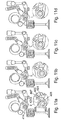
- FIGS 3 , 4 and 5 show a first embodiment of the invention which demonstrates how the invention may be applied to the valve train of Figure 1 .
- the summation lever is constructed in two parts 124a and 124b, that can move relative to one another.
- the first part 124a is supported by the valve actuating rocker 114 by means of a pivot 160 and carries a pair of cam followers 127 that contact the cam profiles 120.
- the second part 124b of the summation lever is connected to the first 124a by a pivot pin 130 received in holes 130a in the first part 124a and a hole 130b in the second part.
- the second part 124b carries a single cam follower roller 126, which is rotatable about an axle pin 129 and contacts the second cam profile 122.
- the second part 124b of the summation lever is also connected by a pin 128a received in holes in the second part 124b to the control spring 128 which controls the motion of the summation lever while the valve is closed
- the summation lever assembly also contains a latch mechanism for selectively preventing relative movement between the two parts of the summation lever.
- the latch mechanism is composed of a nose 150 on the second part 124b of the summation lever and a recess 152 in a latch pin 132 mounted in holes 132a in the first part 124a of the summation lever. By rotating the latch pin 132 to engage or disengage it from the nose 150, the two parts 124a and 124b of the summation lever can either be locked together or allowed to move independently.
- valve lift will occur in the normal manner, as shown in the views of Figures 4a to 4d .
- Figures 3 to 5 uses a rotating latch pin 132 but no means have been shown for rotating the latch pin 132 to switch between valve activation modes. It is important that any changeover between operating modes should take place only while the valve is closed.
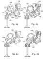
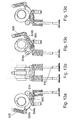
- FIG. 6 to 8 A suitable operating mechanism for rotating the latch pin of the embodiment shown in Figures 3 to 5 is shown in Figures 6 to 8 .
- the previously described components have all been allocated the same reference numerals, but in the 200 series, and only the operating mechanism used to rotate the latch pin 232 need now be described.
- the latch operating mechanism comprises a deactivation lever 262 that is used to rotate the pivot 260 connecting the first part 224a of the summation lever to the valve actuating rocker 214.
- the pivot pin 260 has a recess 261 defining an eccentric that is engaged by a small rod 263 guided for sliding movement in the actuating rocker 214 and urged into the recess 261 by means a U-shaped spring clip 267.
- the opposite end of the rod 263 engages a shoulder on the opposite side of the latch pin 232 from the recess 252.
- the spring 268 used to bias the latch pin 232 is also used to bias the deactivation lever 262.
- the deactivation lever 262 is retained on the end of the pivot pin 260 by a fastener 272 and is coupled for rotation with it by a spring biased lost motion coupling consisting of a narrow key 264 on the deactivation lever 262 engaged in a wider recess 266 in the pivot pin 260, the biasing spring of the pivot pin 260 being designated 265 in Figure 6a .
- the surface of a curved pad on the deactivation lever 262 is concentric with the pivot axis of the actuating rocker 214 and hence the surface maintains the same position throughout the valve lift cycle.
- the spring 268 acts on the lever 262 such that it will return to this position in the absence of any control input.
- the lever 262 may be depressed by a solenoid actuator, or by a hydraulic or mechanical actuator to the position shown in the Figure 7b . This will not immediately move the pivot pin 260 but will move the key 264 to a new position.
- the key acts as a stop limiting the rotation of the pivot pin 260 by the spring 265.
- the pivot pin 260 will be rotated to its new position by the spring 265.
- Figures 6 to 8 thus uses the motion of the summation lever in between valve events to ensure that the transition between valve activation and deactivation will always occur just after the valve has closed, regardless of when the motion of the deactivation lever takes place.
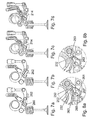
- Figures 9 and 10 show an alternative embodiment which, in place of a rotating latch pin, uses a sliding latch pin 383 engageable in a pair of notches 385 in the second part 324b of the summation lever.
- the system is mechanically operated by moving one of two deactivation levers 381 (only one is shown in Figure 9a ) pivotable about the pivot pin 315 of the actuating rocker 314.
- Each deactivation lever 381 has a projecting spigot 382 that engages between two arms of a torque spring 384 that is itself also free to rotate about the pivot pin 315.
- the ends of the latch pin 383 are straddled by the free ends of the arms of the torque springs 384.
- the springs 384 act as biased lost motion mechanisms connecting the deactivation levers 381 to the ends of the latch pin 383.
- the levers 381 tension the springs 384 and these in turn act to move the latch pin 383 at the first occasion when it is in line with the notches 385 and free to be moved by the force of the springs 384.
- the latch pin 383 is shown in the engaged position from which it can be released to deactivate the associated valve by rotating the levers 381 counter clockwise.
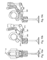
- FIG. 11 uses a similar latching pin 483 to the third embodiment described above, but the deactivation lever 481 forms part of an interlock mechanism such that it can only move at one point in the valve lift cycle.
- forked members 487 straddling the ends of the pin 483 are secured for rotation with the deactivation levers 481.
- the pivot shaft 460 connecting the valve actuating rocker 414 to the summation lever 424a is fixed for rotation with the summation lever 424a and has a profiled cut-out 491 in one end that engages with an interlock pin 489 on the deactivating lever 481.
- Figure 11a shows the interlock pin positioned outside the cut-out 491 in the pivot shaft such that the valve lift is activated.
- Figure 11d shows the interlock pin 489 engaged in the cut-out 491 in the pivot shaft 460 such that the valve lift is deactivated.
- the profile of the cut-out 491 in the pivot shaft 460 prevents the interlock pin 489 from moving freely between these two positions, and it may only do so when the valve has just closed and the summation lever 424a is rotated to its furthest anti-clockwise position as shown in Figures 11b and 11c . Once the summation lever moves away from this position, the deactivation lever is locked in position until after the next valve lift event.
- the latching pins 383 and 483 could be a graded component and this would allow the activated position of the second parts 324b and 424b to be adjusted relative to the main parts 324a and 424a of the summation lever.
- the single roller follower 526 has a hollow axle in which there is received a spring biased latch pin 583a.
- An actuator pin 583b is mounted on the first part 524a of the summation lever and is used to push in the latch pin 583a.
- both of the pins (583a, 583b) that form the latching mechanism act to lock the two parts of the summation lever to one another through the engagement of the latch pin 583a in a hole in one of the cheeks of the first part 524a of the summation lever and through engagement of the actuator pin 583b in the second part 524b of the summation lever.
- the latch is released and the valve is deactivated because the actuator pin 583b is retracted and the latch pin 583b does not project beyond the axle of the roller follower 526.
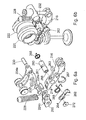
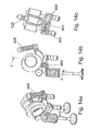
- Figures 13 and 14 show how the latch may be designed to operate hydraulically and also depict how the concept may be applied to a pair of valves rather than a single valve.
- the latching of the two summation lever parts 624a and 624b is achieved by a retractable pin 683 (see Figure 13c ) contained in the first part 624a of the summation lever that can be engaged into a receiving hole or slot in the second part 624b of the summation lever to lock the two parts together.
- the latching pin 683 has a return spring to disengage it from the second part of the summation lever, but the application of oil pressure to the pin will overcome the spring and connect the two parts of the summation lever so that valve lift is enabled. It can be appreciated that a latch could also be designed such that the return spring caused the two parts to be locked together and the application of oil pressure would deactivate the valve lift.
- Oil is supplied to the latch pin 683 via the pivot shaft 660 connecting the summation lever 624a to the valve actuating rocker 614, and this pivot shaft 660 also contains a spool 601 to control the timing of the latching and unlatching events, as shown in Figure 14c .
- Oil under pressure is fed into the pivot shaft 660 from one of the valve actuating rockers 614 and acts to move the spool 601 and compress its return spring 602.
- the spool 601 may only move if there is a vent in the cavity containing the spool return spring, otherwise the position of the spool 601 is maintained via a hydraulic lock.
- the venting of the cavity is achieved via a drilled hole in the pivot shaft 660 and a corresponding hole in the second valve actuating rocker 614 (see Figures 13a ).
Landscapes
- Engineering & Computer Science (AREA)
- Mechanical Engineering (AREA)
- General Engineering & Computer Science (AREA)
- Valve Device For Special Equipments (AREA)
Claims (15)
- Ein Verbrennungsmotor, der Folgendes beinhaltet: einen Ventilmechanismus, welcher zwei Nocken umfasst ('20, '22), die koaxial montiert sind, einen Summierhebel ('24) mit Nockenstößein ('26, '27) in Kontakt mit beiden Nocken ('20, '22), wobei der Summierhebel ('24) im Verhältnis zur momentanen Summe der Hübe der jeweiligen Nocken bewegbar ist, eine Kontrollfeder ('28), um zwischen einem Nockenprofil und seinem/n betreffenden Folgeprofil(en) Kontakt zu halten, und einen das Ventil betätigenden Kipphebel ('14), der einen stationären Drehzapfen aufweist und drehbar mit dem Summierhebel ('24) verbunden ist, welcher dazu dient, das Motorventil abhängig von der Bewegung des Summierhebels ('24) zu öffnen, sodass die Ventilsteuerung, der Ventilhub und die f7auer des Ventilereignisses durch das Variieren der Phasen der beiden Nocken angepasst werden können, dadurch gekennzeichnet, dass der Summierhebel ('24) in zwei Teilen ('24a, '24b) konstruiert ist, die selektiv versperrt und entsperrt werden können, wodurch es möglich ist, den Ventilhub zu deaktivieren, und dass die Bewegung der beiden Teile durch die Kontrollfeder ('28) gesteuert wird, wenn die beiden Teile ('24a, '24b) des Summierhebels voneinander entsperrt werden.
- Ein Verbrennungsmotor, wie in Anspruch 1 beansprucht, worin ein Paar Ventile ('10) mit Hilfe desselben Summierhebels ('24) betrieben werden und beide Ventile ('10) gleichzeitig deaktiviert werden können.
- Ein Verbrennungsmotor, wie in Anspruch 1 oder 2 beansprucht, worin ein Riegelmechanismus zum selektiven Versperren und Entsperren der beiden Teile des Summierhebels ('24a, '24b) einen Verriegelungsbolzen ('32) umfasst, der rotierbar in einem der beiden Teile montiert ist und eine Vertiefung ('52) zur Aufnahme einer Ausbuchtung ('50) aufweist, die von der anderen Seite der beiden Teile ausgeht, wobei der Verriegelungsmechanismus durch Drehung des Verriegelungsbolzens ('32) versperrt und entsperrt wird.
- Ein Verbrennungsmotor, wie in Anspruch 1 oder 2 beansprucht, worin ein Riegelmechanismus zum selektiven Versperren und Entsperren der beiden Teile des Summierhebels ('24a, '24b) einen oder mehrere verschiebbare Stifte ('83) umfasst, die selektiv in einen oder beide Teile des Summierhebels ('24) eingreifen.
- Ein Verbrennungsmotor, wie in Anspruch 4 beansprucht, worin ein Gleitstift (583a, 583b) innerhalb einer Hohlachse eines der Nockenstöf3el ('26, '27) montiert ist.
- Ein Verbrennungsmotor, wie in einem der vorhergehenden Ansprüche beansprucht, worin der Riegelmechanismus zum selektiven Versperren und Entsperren der beiden Teile des Summierhebels ('24a, '24b) mechanisch zwischen seinen versperrten und unversperrten Positionen hin und her bewegt werden kann.
- Ein Verbrennungsmotor, wie in Anspruch 6 beansprucht, worin der Riegelmechanismus durch einen deaktivierungshebel ('81) betrieben wird, der um eine gemeinsame Achse mit jener des Kipphebels ('14), der das Ventil betätigt, rotierbar ist.
- Ein Verbrennungsmotor, wie in Anspruch 6 beansprucht, worin der Riegelmechanismus durch die Rotation der Schwingenachse ('60) gesteuert wird, welche den Kipphebel ('14), der das Ventil betätigt, sowie den Summierhebel ('24) verbindet.
- Ein Verbrennungsmotor, wie in einem der Ansprüche 6 bis 8 beansprucht, worin die Steuerung der Veränderung des Riegelstatus durch die Bewegung des Summierhebels ('24) vorgeschrieben wird.
- Ein Verbrennungsmotor, wie in Anspruch 9 beansprucht, worin die Bewegung des Summierhebels ('24) direkt verwendet wird, um das Verriegelungselement ('32, '83) zu bewegen.
- Ein Verbrennungsmotor, wie in Anspruch 9 beansprucht, worin ein Sperrmechanismus verwendet wird, um den Verriegelungsmechanismus mit der Bewegung des Summierhebels ('24) zu koordinieren.
- Ein Verbrennungsmotor, wie in einem der Ansprüche 1 bis 5 beansprucht, worin der Riegelmechanismus hydraulisch betrieben wird.
- Ein Verbrennungsmotor, wie in Anspruch 12 beansprucht, worin die Steuerung der Veränderung des Riegelstatus durch die Bewegung des Summierhebels ('24) vorgeschrieben wird und eine Spule (601) verwendet wird, um die Riegelsteuerung unabhängig von jener der Öldruckversorgung zu kontrollieren.
- Ein Verbrennungsmotor, wie in Anspruch 12 beansprucht, worin die Steuerung der Veränderung des Riegelstatus durch die Bewegung des Summierhebels ('24) vorgeschrieben wird und eine hydraulische Sperre verwendet wird, um den Verriegelungsmechanismus mit der Bewegung des Summierhebels ('24) zu koordinieren.
- Ein Verbrennungsmotor, wie in einem der vorhergehenden Ansprüche beansprucht, worin der Abstand im Kipphebelsystem justierbar ist, indem die relativen Positionen der beiden Teile des Summierhebels ('24a, '24b) verändert werden, wenn der Hebel in dem Zustand, in dem das Ventil betätigt wird, verriegelt wird.
Applications Claiming Priority (2)
| Application Number | Priority Date | Filing Date | Title |
|---|---|---|---|
| GB0801050.6A GB2456760B (en) | 2008-01-22 | 2008-01-22 | Variable valve actuating mechanism with lift deactivation |
| PCT/GB2008/051198 WO2009092995A1 (en) | 2008-01-22 | 2008-12-18 | Variable valve actuating mechanism with lift deactivation |
Publications (2)
| Publication Number | Publication Date |
|---|---|
| EP2242912A1 EP2242912A1 (de) | 2010-10-27 |
| EP2242912B1 true EP2242912B1 (de) | 2012-10-31 |
Family
ID=39166090
Family Applications (1)
| Application Number | Title | Priority Date | Filing Date |
|---|---|---|---|
| EP08871486A Not-in-force EP2242912B1 (de) | 2008-01-22 | 2008-12-18 | Variabler ventilbetätigungsmechanismus mit hebedeaktivierung |
Country Status (4)
| Country | Link |
|---|---|
| US (1) | US8365691B2 (de) |
| EP (1) | EP2242912B1 (de) |
| GB (1) | GB2456760B (de) |
| WO (1) | WO2009092995A1 (de) |
Families Citing this family (12)
| Publication number | Priority date | Publication date | Assignee | Title |
|---|---|---|---|---|
| GB2473250A (en) * | 2009-09-07 | 2011-03-09 | Mechadyne Plc | Variable valve actuating system for i.c. engines |
| GB2480638A (en) * | 2010-05-26 | 2011-11-30 | Mechadyne Plc | Assembly of a valve operating system incorporating a cam summation mechanism |
| EP2762692B1 (de) * | 2013-02-04 | 2015-04-08 | Mechadyne International Limited | Nockenprofil-Summierungsmechanismus |
| DE102013109414A1 (de) * | 2013-08-29 | 2015-03-05 | Fev Gmbh | Ventilsteuerung für eine Brennkraftmaschine sowie Brennkraftmaschine |
| CN103790669B (zh) * | 2014-01-23 | 2017-07-28 | 长城汽车股份有限公司 | 用于发动机的配气机构及具有其的车辆 |
| KR101575339B1 (ko) | 2014-10-21 | 2015-12-07 | 현대자동차 주식회사 | 비대칭 cda 엔진 |
| WO2018038757A1 (en) * | 2016-08-23 | 2018-03-01 | Eaton Corporation | Two step rocker arm having side by side roller configuration |
| EP3296531A1 (de) * | 2016-09-14 | 2018-03-21 | Mechadyne International Limited | Motorventilsystem |
| US11566544B2 (en) | 2018-08-09 | 2023-01-31 | Eaton Intelligent Power Limited | Rocker arm assembly with lost motion spring |
| WO2020030298A1 (en) | 2018-08-09 | 2020-02-13 | Eaton Intelligent Power Limited | Deactivating rocker arm having two-stage latch pin |
| WO2020211981A1 (en) * | 2019-04-17 | 2020-10-22 | Eaton Intelligent Power Limited | Rocker arm assembly with lost motion spring capsule |
| US11047267B2 (en) * | 2019-04-25 | 2021-06-29 | Mechadyne International Ltd. | Variable valve lift system |
Family Cites Families (17)
| Publication number | Priority date | Publication date | Assignee | Title |
|---|---|---|---|---|
| US4203397A (en) * | 1978-06-14 | 1980-05-20 | Eaton Corporation | Engine valve control mechanism |
| JP2890236B2 (ja) * | 1994-02-28 | 1999-05-10 | 本田技研工業株式会社 | 内燃機関の動弁制御装置 |
| DE19701201A1 (de) | 1997-01-15 | 1998-07-23 | Daimler Benz Ag | Variable Ventilsteuerung für Brennkraftmaschinen |
| DE19802738A1 (de) | 1998-01-26 | 1999-07-29 | Opel Adam Ag | Vorrichtung zur variablen Steuerung eines Ventils einer Brennkraftmaschine |
| JP3799944B2 (ja) * | 2000-03-21 | 2006-07-19 | トヨタ自動車株式会社 | 内燃機関の可変動弁機構および吸気量制御装置 |
| GB2378729A (en) | 2001-08-18 | 2003-02-19 | Mechadyne Plc | Adjustable engine valve control system |
| EP1426596B1 (de) | 2002-11-28 | 2006-05-31 | STMicroelectronics S.r.l. | Architektur einer elektronischen Vorrichtung zum Ermitteln der Betriebsphase einer Brennkraftmaschine |
| DE10326238A1 (de) * | 2002-12-24 | 2005-02-03 | Levon Grigorjan | Vollvariable Ventilsteuerung für Brennkraftmaschinen |
| DE10303601A1 (de) | 2003-01-30 | 2004-08-12 | Mahle Ventiltrieb Gmbh | Ventilsteuerung |
| DE10316189A1 (de) * | 2003-04-09 | 2004-10-28 | Ina-Schaeffler Kg | Schlepphebel eines Ventiltriebs einer Brennkraftmaschine |
| JP2007526423A (ja) * | 2004-03-03 | 2007-09-13 | ティムケン ユーエス コーポレーション | 切換え式フィンガ従動子アセンブリ |
| WO2006007817A1 (de) | 2004-07-17 | 2006-01-26 | Mahle Ventiltrieb Gmbh | Steuereinrichtung für ein ventil, insbesondere ein gaswechselventil eines verbrennungsmotors |
| US7121241B1 (en) * | 2006-01-10 | 2006-10-17 | Eaton Corporation | Valve control system including deactivating rocker arm |
| US7162983B1 (en) * | 2006-02-22 | 2007-01-16 | Gm Global Technology Operations, Inc. | Valve actuator assembly for variable displacement of an engine valve |
| GB2438208A (en) * | 2006-05-19 | 2007-11-21 | Mechadyne Plc | I.c. engine poppet valve actuating mechanism |
| GB2438628A (en) * | 2006-05-31 | 2007-12-05 | Mechadyne Plc | Engine with variable valve actuating mechanism |
| GB2449096A (en) * | 2007-05-10 | 2008-11-12 | Mechadyne Plc | Variable valve actuating system for i.c. engines |
-
2008
- 2008-01-22 GB GB0801050.6A patent/GB2456760B/en not_active Expired - Fee Related
- 2008-12-18 EP EP08871486A patent/EP2242912B1/de not_active Not-in-force
- 2008-12-18 US US12/864,042 patent/US8365691B2/en not_active Expired - Fee Related
- 2008-12-18 WO PCT/GB2008/051198 patent/WO2009092995A1/en not_active Ceased
Also Published As
| Publication number | Publication date |
|---|---|
| WO2009092995A1 (en) | 2009-07-30 |
| GB2456760A (en) | 2009-07-29 |
| GB2456760B (en) | 2012-05-23 |
| US8365691B2 (en) | 2013-02-05 |
| EP2242912A1 (de) | 2010-10-27 |
| GB0801050D0 (en) | 2008-02-27 |
| US20100294222A1 (en) | 2010-11-25 |
Similar Documents
| Publication | Publication Date | Title |
|---|---|---|
| EP2242912B1 (de) | Variabler ventilbetätigungsmechanismus mit hebedeaktivierung | |
| EP2839123B1 (de) | Schaltbarer kipphebel | |
| RU2723650C2 (ru) | Регулируемый клапанный механизм, имеющий коромысло | |
| US6615782B1 (en) | Two-step finger follower rocker arm | |
| CN108699926B (zh) | 致动装置 | |
| US4726332A (en) | Variable valve mechanism for internal combustion engines | |
| US6668775B2 (en) | Lock-pin cartridge for a two-step finger follower rocker arm | |
| EP1857642A1 (de) | Ventilbetätigungsmechanismus | |
| US4690110A (en) | Variable valve mechanism for internal combustion engines | |
| GB2237326A (en) | I.c.engine rocker valve gear | |
| WO2002049873A3 (en) | Operating mechanism for control of recliner assembly | |
| WO2017060496A1 (en) | Rocker arm assembly for an internal combustion engine | |
| EP1544423A2 (de) | Rollenschlepphebel zur Ventilabschaltung | |
| US6655331B2 (en) | Piston-type internal-combustion engine having activatable, mechanically actuated cylinder valves | |
| US4617880A (en) | Valve actuating apparatus for optionally resting the operation of a valve in internal combustion engine | |
| US6382150B1 (en) | Desmodromic oscillating cam actuator with hydraulic lash adjuster | |
| US6640759B1 (en) | Two-step finger follower rocker arm | |
| WO2008153191A2 (en) | Variable valve apparatus | |
| EP1669559B1 (de) | Ventiltriebmechanismus | |
| CN100451404C (zh) | 齿轮选择器机构 | |
| CN113356958B (zh) | 摇臂 | |
| JPH0550561B2 (de) | ||
| EP1568859B1 (de) | Kipphebeleinrichtung für Ventilsteuerung | |
| GB2448167A (en) | I.c. engine valve actuating system | |
| JPS61250318A (ja) | エンジンの動弁装置 |
Legal Events
| Date | Code | Title | Description |
|---|---|---|---|
| PUAI | Public reference made under article 153(3) epc to a published international application that has entered the european phase |
Free format text: ORIGINAL CODE: 0009012 |
|
| 17P | Request for examination filed |
Effective date: 20100709 |
|
| AK | Designated contracting states |
Kind code of ref document: A1 Designated state(s): AT BE BG CH CY CZ DE DK EE ES FI FR GB GR HR HU IE IS IT LI LT LU LV MC MT NL NO PL PT RO SE SI SK TR |
|
| AX | Request for extension of the european patent |
Extension state: AL BA MK RS |
|
| DAX | Request for extension of the european patent (deleted) | ||
| GRAP | Despatch of communication of intention to grant a patent |
Free format text: ORIGINAL CODE: EPIDOSNIGR1 |
|
| GRAS | Grant fee paid |
Free format text: ORIGINAL CODE: EPIDOSNIGR3 |
|
| GRAA | (expected) grant |
Free format text: ORIGINAL CODE: 0009210 |
|
| AK | Designated contracting states |
Kind code of ref document: B1 Designated state(s): AT BE BG CH CY CZ DE DK EE ES FI FR GR HR HU IE IS IT LI LT LU LV MC MT NL NO PL PT RO SE SI SK TR |
|
| RBV | Designated contracting states (corrected) |
Designated state(s): AT BE BG CH CY CZ DE DK EE ES FI FR GR HR HU IE IS IT LI LT LU LV MC MT NL NO PL PT RO SE SI SK TR |
|
| REG | Reference to a national code |
Ref country code: CH Ref legal event code: EP |
|
| REG | Reference to a national code |
Ref country code: AT Ref legal event code: REF Ref document number: 582141 Country of ref document: AT Kind code of ref document: T Effective date: 20121115 |
|
| REG | Reference to a national code |
Ref country code: IE Ref legal event code: FG4D |
|
| REG | Reference to a national code |
Ref country code: DE Ref legal event code: R096 Ref document number: 602008019879 Country of ref document: DE Effective date: 20121227 |
|
| REG | Reference to a national code |
Ref country code: AT Ref legal event code: MK05 Ref document number: 582141 Country of ref document: AT Kind code of ref document: T Effective date: 20121031 |
|
| REG | Reference to a national code |
Ref country code: LT Ref legal event code: MG4D |
|
| REG | Reference to a national code |
Ref country code: NL Ref legal event code: VDEP Effective date: 20121031 |
|
| PG25 | Lapsed in a contracting state [announced via postgrant information from national office to epo] |
Ref country code: SE Free format text: LAPSE BECAUSE OF FAILURE TO SUBMIT A TRANSLATION OF THE DESCRIPTION OR TO PAY THE FEE WITHIN THE PRESCRIBED TIME-LIMIT Effective date: 20121031 Ref country code: HR Free format text: LAPSE BECAUSE OF FAILURE TO SUBMIT A TRANSLATION OF THE DESCRIPTION OR TO PAY THE FEE WITHIN THE PRESCRIBED TIME-LIMIT Effective date: 20121031 Ref country code: LT Free format text: LAPSE BECAUSE OF FAILURE TO SUBMIT A TRANSLATION OF THE DESCRIPTION OR TO PAY THE FEE WITHIN THE PRESCRIBED TIME-LIMIT Effective date: 20121031 Ref country code: ES Free format text: LAPSE BECAUSE OF FAILURE TO SUBMIT A TRANSLATION OF THE DESCRIPTION OR TO PAY THE FEE WITHIN THE PRESCRIBED TIME-LIMIT Effective date: 20130211 Ref country code: NL Free format text: LAPSE BECAUSE OF FAILURE TO SUBMIT A TRANSLATION OF THE DESCRIPTION OR TO PAY THE FEE WITHIN THE PRESCRIBED TIME-LIMIT Effective date: 20121031 Ref country code: NO Free format text: LAPSE BECAUSE OF FAILURE TO SUBMIT A TRANSLATION OF THE DESCRIPTION OR TO PAY THE FEE WITHIN THE PRESCRIBED TIME-LIMIT Effective date: 20130131 Ref country code: FI Free format text: LAPSE BECAUSE OF FAILURE TO SUBMIT A TRANSLATION OF THE DESCRIPTION OR TO PAY THE FEE WITHIN THE PRESCRIBED TIME-LIMIT Effective date: 20121031 Ref country code: IS Free format text: LAPSE BECAUSE OF FAILURE TO SUBMIT A TRANSLATION OF THE DESCRIPTION OR TO PAY THE FEE WITHIN THE PRESCRIBED TIME-LIMIT Effective date: 20130228 |
|
| PG25 | Lapsed in a contracting state [announced via postgrant information from national office to epo] |
Ref country code: PT Free format text: LAPSE BECAUSE OF FAILURE TO SUBMIT A TRANSLATION OF THE DESCRIPTION OR TO PAY THE FEE WITHIN THE PRESCRIBED TIME-LIMIT Effective date: 20130228 Ref country code: GR Free format text: LAPSE BECAUSE OF FAILURE TO SUBMIT A TRANSLATION OF THE DESCRIPTION OR TO PAY THE FEE WITHIN THE PRESCRIBED TIME-LIMIT Effective date: 20130201 Ref country code: LV Free format text: LAPSE BECAUSE OF FAILURE TO SUBMIT A TRANSLATION OF THE DESCRIPTION OR TO PAY THE FEE WITHIN THE PRESCRIBED TIME-LIMIT Effective date: 20121031 Ref country code: SI Free format text: LAPSE BECAUSE OF FAILURE TO SUBMIT A TRANSLATION OF THE DESCRIPTION OR TO PAY THE FEE WITHIN THE PRESCRIBED TIME-LIMIT Effective date: 20121031 Ref country code: BE Free format text: LAPSE BECAUSE OF FAILURE TO SUBMIT A TRANSLATION OF THE DESCRIPTION OR TO PAY THE FEE WITHIN THE PRESCRIBED TIME-LIMIT Effective date: 20121031 Ref country code: PL Free format text: LAPSE BECAUSE OF FAILURE TO SUBMIT A TRANSLATION OF THE DESCRIPTION OR TO PAY THE FEE WITHIN THE PRESCRIBED TIME-LIMIT Effective date: 20121031 |
|
| PG25 | Lapsed in a contracting state [announced via postgrant information from national office to epo] |
Ref country code: AT Free format text: LAPSE BECAUSE OF FAILURE TO SUBMIT A TRANSLATION OF THE DESCRIPTION OR TO PAY THE FEE WITHIN THE PRESCRIBED TIME-LIMIT Effective date: 20121031 |
|
| PG25 | Lapsed in a contracting state [announced via postgrant information from national office to epo] |
Ref country code: DK Free format text: LAPSE BECAUSE OF FAILURE TO SUBMIT A TRANSLATION OF THE DESCRIPTION OR TO PAY THE FEE WITHIN THE PRESCRIBED TIME-LIMIT Effective date: 20121031 Ref country code: MC Free format text: LAPSE BECAUSE OF NON-PAYMENT OF DUE FEES Effective date: 20121231 Ref country code: BG Free format text: LAPSE BECAUSE OF FAILURE TO SUBMIT A TRANSLATION OF THE DESCRIPTION OR TO PAY THE FEE WITHIN THE PRESCRIBED TIME-LIMIT Effective date: 20130131 Ref country code: SK Free format text: LAPSE BECAUSE OF FAILURE TO SUBMIT A TRANSLATION OF THE DESCRIPTION OR TO PAY THE FEE WITHIN THE PRESCRIBED TIME-LIMIT Effective date: 20121031 Ref country code: EE Free format text: LAPSE BECAUSE OF FAILURE TO SUBMIT A TRANSLATION OF THE DESCRIPTION OR TO PAY THE FEE WITHIN THE PRESCRIBED TIME-LIMIT Effective date: 20121031 Ref country code: CZ Free format text: LAPSE BECAUSE OF FAILURE TO SUBMIT A TRANSLATION OF THE DESCRIPTION OR TO PAY THE FEE WITHIN THE PRESCRIBED TIME-LIMIT Effective date: 20121031 |
|
| REG | Reference to a national code |
Ref country code: CH Ref legal event code: PL |
|
| PG25 | Lapsed in a contracting state [announced via postgrant information from national office to epo] |
Ref country code: IT Free format text: LAPSE BECAUSE OF FAILURE TO SUBMIT A TRANSLATION OF THE DESCRIPTION OR TO PAY THE FEE WITHIN THE PRESCRIBED TIME-LIMIT Effective date: 20121031 Ref country code: RO Free format text: LAPSE BECAUSE OF FAILURE TO SUBMIT A TRANSLATION OF THE DESCRIPTION OR TO PAY THE FEE WITHIN THE PRESCRIBED TIME-LIMIT Effective date: 20121031 |
|
| PLBE | No opposition filed within time limit |
Free format text: ORIGINAL CODE: 0009261 |
|
| STAA | Information on the status of an ep patent application or granted ep patent |
Free format text: STATUS: NO OPPOSITION FILED WITHIN TIME LIMIT |
|
| REG | Reference to a national code |
Ref country code: IE Ref legal event code: MM4A |
|
| REG | Reference to a national code |
Ref country code: FR Ref legal event code: ST Effective date: 20130830 |
|
| 26N | No opposition filed |
Effective date: 20130801 |
|
| PG25 | Lapsed in a contracting state [announced via postgrant information from national office to epo] |
Ref country code: CH Free format text: LAPSE BECAUSE OF NON-PAYMENT OF DUE FEES Effective date: 20121231 Ref country code: LI Free format text: LAPSE BECAUSE OF NON-PAYMENT OF DUE FEES Effective date: 20121231 Ref country code: IE Free format text: LAPSE BECAUSE OF NON-PAYMENT OF DUE FEES Effective date: 20121218 |
|
| REG | Reference to a national code |
Ref country code: DE Ref legal event code: R097 Ref document number: 602008019879 Country of ref document: DE Effective date: 20130801 |
|
| PG25 | Lapsed in a contracting state [announced via postgrant information from national office to epo] |
Ref country code: FR Free format text: LAPSE BECAUSE OF NON-PAYMENT OF DUE FEES Effective date: 20130102 Ref country code: CY Free format text: LAPSE BECAUSE OF FAILURE TO SUBMIT A TRANSLATION OF THE DESCRIPTION OR TO PAY THE FEE WITHIN THE PRESCRIBED TIME-LIMIT Effective date: 20121031 Ref country code: MT Free format text: LAPSE BECAUSE OF FAILURE TO SUBMIT A TRANSLATION OF THE DESCRIPTION OR TO PAY THE FEE WITHIN THE PRESCRIBED TIME-LIMIT Effective date: 20121031 |
|
| REG | Reference to a national code |
Ref country code: DE Ref legal event code: R082 Ref document number: 602008019879 Country of ref document: DE Representative=s name: PATENTANWAELTE TER SMITTEN EBERLEIN RUETTEN PA, DE Ref country code: DE Ref legal event code: R082 Ref document number: 602008019879 Country of ref document: DE Representative=s name: PATENTANWAELTE TER SMITTEN EBERLEIN-VAN HOOF R, DE |
|
| PG25 | Lapsed in a contracting state [announced via postgrant information from national office to epo] |
Ref country code: TR Free format text: LAPSE BECAUSE OF FAILURE TO SUBMIT A TRANSLATION OF THE DESCRIPTION OR TO PAY THE FEE WITHIN THE PRESCRIBED TIME-LIMIT Effective date: 20121031 |
|
| PG25 | Lapsed in a contracting state [announced via postgrant information from national office to epo] |
Ref country code: LU Free format text: LAPSE BECAUSE OF NON-PAYMENT OF DUE FEES Effective date: 20121218 |
|
| PG25 | Lapsed in a contracting state [announced via postgrant information from national office to epo] |
Ref country code: HU Free format text: LAPSE BECAUSE OF FAILURE TO SUBMIT A TRANSLATION OF THE DESCRIPTION OR TO PAY THE FEE WITHIN THE PRESCRIBED TIME-LIMIT Effective date: 20081218 |
|
| REG | Reference to a national code |
Ref country code: DE Ref legal event code: R082 Ref document number: 602008019879 Country of ref document: DE Representative=s name: TERPATENT PATENTANWAELTE TER SMITTEN EBERLEIN-, DE |
|
| PGFP | Annual fee paid to national office [announced via postgrant information from national office to epo] |
Ref country code: DE Payment date: 20211220 Year of fee payment: 14 |
|
| REG | Reference to a national code |
Ref country code: DE Ref legal event code: R119 Ref document number: 602008019879 Country of ref document: DE |
|
| PG25 | Lapsed in a contracting state [announced via postgrant information from national office to epo] |
Ref country code: DE Free format text: LAPSE BECAUSE OF NON-PAYMENT OF DUE FEES Effective date: 20230701 |