EP2242201B1 - Method and device for transmitting uplink signal including data and control information via uplink channel - Google Patents
Method and device for transmitting uplink signal including data and control information via uplink channel Download PDFInfo
- Publication number
- EP2242201B1 EP2242201B1 EP10171033.3A EP10171033A EP2242201B1 EP 2242201 B1 EP2242201 B1 EP 2242201B1 EP 10171033 A EP10171033 A EP 10171033A EP 2242201 B1 EP2242201 B1 EP 2242201B1
- Authority
- EP
- European Patent Office
- Prior art keywords
- data
- control information
- uplink signal
- pusch
- cqi
- Prior art date
- Legal status (The legal status is an assumption and is not a legal conclusion. Google has not performed a legal analysis and makes no representation as to the accuracy of the status listed.)
- Active
Links
- 238000000034 method Methods 0.000 title claims abstract description 75
- 230000005540 biological transmission Effects 0.000 claims description 44
- 238000003908 quality control method Methods 0.000 claims description 17
- 125000004122 cyclic group Chemical group 0.000 claims description 6
- 239000011159 matrix material Substances 0.000 claims description 6
- 101000741965 Homo sapiens Inactive tyrosine-protein kinase PRAG1 Proteins 0.000 claims 4
- 102100038659 Inactive tyrosine-protein kinase PRAG1 Human genes 0.000 claims 4
- 230000006870 function Effects 0.000 description 17
- 238000013507 mapping Methods 0.000 description 11
- 238000013139 quantization Methods 0.000 description 11
- 238000004891 communication Methods 0.000 description 8
- 239000000470 constituent Substances 0.000 description 7
- 238000010586 diagram Methods 0.000 description 6
- 238000004364 calculation method Methods 0.000 description 5
- 230000011218 segmentation Effects 0.000 description 4
- 206010009944 Colon cancer Diseases 0.000 description 3
- FFBHFFJDDLITSX-UHFFFAOYSA-N benzyl N-[2-hydroxy-4-(3-oxomorpholin-4-yl)phenyl]carbamate Chemical compound OC1=C(NC(=O)OCC2=CC=CC=C2)C=CC(=C1)N1CCOCC1=O FFBHFFJDDLITSX-UHFFFAOYSA-N 0.000 description 2
- 230000015556 catabolic process Effects 0.000 description 2
- 230000001413 cellular effect Effects 0.000 description 2
- 238000006731 degradation reaction Methods 0.000 description 2
- 230000001419 dependent effect Effects 0.000 description 2
- 230000010363 phase shift Effects 0.000 description 2
- 208000031481 Pathologic Constriction Diseases 0.000 description 1
- 238000003491 array Methods 0.000 description 1
- 238000001514 detection method Methods 0.000 description 1
- 239000004973 liquid crystal related substance Substances 0.000 description 1
- 230000007774 longterm Effects 0.000 description 1
- 238000010295 mobile communication Methods 0.000 description 1
- 230000003595 spectral effect Effects 0.000 description 1
- 239000013598 vector Substances 0.000 description 1
Images


Classifications
-
- H—ELECTRICITY
- H04—ELECTRIC COMMUNICATION TECHNIQUE
- H04L—TRANSMISSION OF DIGITAL INFORMATION, e.g. TELEGRAPHIC COMMUNICATION
- H04L1/00—Arrangements for detecting or preventing errors in the information received
- H04L1/0001—Systems modifying transmission characteristics according to link quality, e.g. power backoff
- H04L1/0023—Systems modifying transmission characteristics according to link quality, e.g. power backoff characterised by the signalling
- H04L1/0028—Formatting
- H04L1/0031—Multiple signaling transmission
-
- H—ELECTRICITY
- H04—ELECTRIC COMMUNICATION TECHNIQUE
- H04L—TRANSMISSION OF DIGITAL INFORMATION, e.g. TELEGRAPHIC COMMUNICATION
- H04L1/00—Arrangements for detecting or preventing errors in the information received
- H04L1/004—Arrangements for detecting or preventing errors in the information received by using forward error control
- H04L1/0056—Systems characterized by the type of code used
- H04L1/0071—Use of interleaving
-
- H—ELECTRICITY
- H04—ELECTRIC COMMUNICATION TECHNIQUE
- H04L—TRANSMISSION OF DIGITAL INFORMATION, e.g. TELEGRAPHIC COMMUNICATION
- H04L1/00—Arrangements for detecting or preventing errors in the information received
- H04L1/004—Arrangements for detecting or preventing errors in the information received by using forward error control
- H04L1/0072—Error control for data other than payload data, e.g. control data
-
- H—ELECTRICITY
- H04—ELECTRIC COMMUNICATION TECHNIQUE
- H04L—TRANSMISSION OF DIGITAL INFORMATION, e.g. TELEGRAPHIC COMMUNICATION
- H04L1/00—Arrangements for detecting or preventing errors in the information received
- H04L1/12—Arrangements for detecting or preventing errors in the information received by using return channel
- H04L1/16—Arrangements for detecting or preventing errors in the information received by using return channel in which the return channel carries supervisory signals, e.g. repetition request signals
- H04L1/1607—Details of the supervisory signal
- H04L1/1671—Details of the supervisory signal the supervisory signal being transmitted together with control information
-
- H—ELECTRICITY
- H04—ELECTRIC COMMUNICATION TECHNIQUE
- H04L—TRANSMISSION OF DIGITAL INFORMATION, e.g. TELEGRAPHIC COMMUNICATION
- H04L1/00—Arrangements for detecting or preventing errors in the information received
- H04L1/12—Arrangements for detecting or preventing errors in the information received by using return channel
- H04L1/16—Arrangements for detecting or preventing errors in the information received by using return channel in which the return channel carries supervisory signals, e.g. repetition request signals
- H04L1/18—Automatic repetition systems, e.g. Van Duuren systems
- H04L1/1812—Hybrid protocols; Hybrid automatic repeat request [HARQ]
- H04L1/1819—Hybrid protocols; Hybrid automatic repeat request [HARQ] with retransmission of additional or different redundancy
-
- H—ELECTRICITY
- H04—ELECTRIC COMMUNICATION TECHNIQUE
- H04L—TRANSMISSION OF DIGITAL INFORMATION, e.g. TELEGRAPHIC COMMUNICATION
- H04L1/00—Arrangements for detecting or preventing errors in the information received
- H04L1/12—Arrangements for detecting or preventing errors in the information received by using return channel
- H04L1/16—Arrangements for detecting or preventing errors in the information received by using return channel in which the return channel carries supervisory signals, e.g. repetition request signals
- H04L1/18—Automatic repetition systems, e.g. Van Duuren systems
- H04L1/1822—Automatic repetition systems, e.g. Van Duuren systems involving configuration of automatic repeat request [ARQ] with parallel processes
-
- H—ELECTRICITY
- H04—ELECTRIC COMMUNICATION TECHNIQUE
- H04L—TRANSMISSION OF DIGITAL INFORMATION, e.g. TELEGRAPHIC COMMUNICATION
- H04L65/00—Network arrangements, protocols or services for supporting real-time applications in data packet communication
- H04L65/10—Architectures or entities
- H04L65/1016—IP multimedia subsystem [IMS]
-
- H—ELECTRICITY
- H04—ELECTRIC COMMUNICATION TECHNIQUE
- H04L—TRANSMISSION OF DIGITAL INFORMATION, e.g. TELEGRAPHIC COMMUNICATION
- H04L65/00—Network arrangements, protocols or services for supporting real-time applications in data packet communication
- H04L65/1066—Session management
- H04L65/1069—Session establishment or de-establishment
-
- H—ELECTRICITY
- H04—ELECTRIC COMMUNICATION TECHNIQUE
- H04L—TRANSMISSION OF DIGITAL INFORMATION, e.g. TELEGRAPHIC COMMUNICATION
- H04L65/00—Network arrangements, protocols or services for supporting real-time applications in data packet communication
- H04L65/60—Network streaming of media packets
- H04L65/61—Network streaming of media packets for supporting one-way streaming services, e.g. Internet radio
- H04L65/612—Network streaming of media packets for supporting one-way streaming services, e.g. Internet radio for unicast
-
- H—ELECTRICITY
- H04—ELECTRIC COMMUNICATION TECHNIQUE
- H04W—WIRELESS COMMUNICATION NETWORKS
- H04W72/00—Local resource management
-
- H—ELECTRICITY
- H04—ELECTRIC COMMUNICATION TECHNIQUE
- H04W—WIRELESS COMMUNICATION NETWORKS
- H04W72/00—Local resource management
- H04W72/04—Wireless resource allocation
-
- H—ELECTRICITY
- H04—ELECTRIC COMMUNICATION TECHNIQUE
- H04W—WIRELESS COMMUNICATION NETWORKS
- H04W72/00—Local resource management
- H04W72/20—Control channels or signalling for resource management
- H04W72/21—Control channels or signalling for resource management in the uplink direction of a wireless link, i.e. towards the network
-
- H—ELECTRICITY
- H04—ELECTRIC COMMUNICATION TECHNIQUE
- H04L—TRANSMISSION OF DIGITAL INFORMATION, e.g. TELEGRAPHIC COMMUNICATION
- H04L65/00—Network arrangements, protocols or services for supporting real-time applications in data packet communication
- H04L65/1066—Session management
- H04L65/1101—Session protocols
- H04L65/1104—Session initiation protocol [SIP]
Definitions
- the present invention relates to a method for transmitting an uplink signal including control information and data through an uplink channel.
- a downlink physical channel includes a physical downlink shared channel (PDSCH), a physical broadcast channel (PBCH), a physical multicast channel (PMCH), a physical control format indicator channel (PCFICH), a physical downlink control channel (PDCCH), and a physical hybrid ARQ indicator channel (PHICH).
- An uplink physical channel includes a physical uplink shared channel (PUSCH), a physical uplink control channel (PUCCH), and a physical random access channel (PRACH).
- a downlink transport channel includes a broadcast channel (BCH), a downlink shared channel (DL-SCH), a paging channel (PCH), and a multicast channel (MCH).
- An uplink transport channel includes an uplink shared channel (UL-SCH) and a random access channel (RACH).
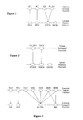
- FIG. 1 illustrates a mapping relationship between a downlink physical channel and a downlink transport channel.
- FIG. 2 illustrates a mapping relationship between an uplink physical channel and an uplink transport channel. The above-described physical channels and transport channels are mapped to each other as illustrated in FIGs. 1 and 2 .
- a logical channel classified as a control channel includes a broadcast control channel (BCCH), a paging control channel (PCCH), a common control channel (CCCH), a multicast control channel (MCCH), and a dedicated control channel (DCCH).
- a logical channel classified as a traffic channel includes a dedicated traffic channel (DTCH) and a multicast traffic channel (MTCH).
- FIG. 3 illustrates a mapping relationship between a downlink transport channel and a downlink logical channel.
- FIG. 4 illustrates a mapping relationship between an uplink transport channel and an uplink logical channel.
- an uplink/downlink data packet is transmitted in units of subframes.
- One subframe is defined as a prescribed time duration including a plurality of OFDM symbols.
- the 3GPP supports radio frame structure type 1 applicable to frequency division duplex (FDD) and radio frame structure type 2 applicable to time division duplex (TDD).
- FDD frequency division duplex
- TDD time division duplex
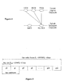
- FIG. 5 illustrates the radio frame structure type 1.
- the radio frame type 1 consists of 10 subframes.
- One subframe consists of 2 slots.
- FIG. 6 illustrates the radio frame structure type 2.
- the radio frame type 2 is comprised of two half-frames. Each half-frame consists of 5 subframes, a downlink pilot time slot (DwPTS), a guard period (GP), and an uplink pilot time slot (UpPTS).
- DwPTS downlink pilot time slot
- GP guard period
- UpPTS uplink pilot time slot
- One subframe consists of two slots.
- the DwPTS is used for an initial cell search, for synchronization or for channel estimation.
- the UpPTS is used for channel estimation in an evolved Node B (eNB), uplink transmission synchronization of a User Equipment (UE).
- eNB evolved Node B
- UE User Equipment
- the GP is an interval for eliminating interference caused by multi-path delay of downlink signal between uplink and downlink. Namely, irrespective of a radio frame type, one subframe consists of two slots.
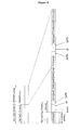
- FIG. 7 illustrates a downlink slot structure of LTE.
- a signal transmitted in each slot may be represented by a resource grid comprised of subcarriers and OFDM symbols.
- denotes the number of resource blocks (RBs) in a downlink denotes the number of subcarriers constituting one RB, and denotes the number of OFDM symbols in one downlink slot.
- RBs resource blocks
- FIG. 8 illustrates an uplink slot structure of LTE.
- a signal transmitted in each slot may be represented by a resource grid comprised of subcarriers and OFDM symbols.
- denotes the number of resource blocks (RBs) in an uplink denotes the number of subcarriers constituting one RB, and denotes the number of OFDM symbols in one uplink slot.
- a resource element refers to one subcarrier and one OFDM symbol as a resource unit defined by indexes (a, b) (where a is an index on a frequency domain and b is an index on a time domain) within the uplink slot and the downlink slot.
- the eNB transmits control information to a downlink to control a UL-SCH which is an uplink transport channel.
- the control information transmitted to the downlink informs the UE of the number of RBs transmitted through the UL-SCH and a modulation order.
- the control information informs the UE of a payload size of the data.
- the payload size may be defined as the sum of the size of information (e.g., the size of data, or the size of control information) transmitted from a medium access control (MAC) layer and the size of cyclic redundancy check (CRC) attached arbitrarily to the information in a physical layer.
- MAC medium access control
- CRC cyclic redundancy check
- the payload of the control information may not include the size of the CRC because the CRC cannot be attached to the control information according to the size of the control information before the CRC is attached to the control information. Specifically, if the size of the control information to which the CRC is not attached is smaller than or equal to 11 bits, the CRC is not attached to the control information. In addition, if the size of the control information to which the CRC is not attached is greater than or equal to 12 bits, the CRC is attached to the control information.
- Data and control information may be multiplexed together and transmitted through the UL-SCH.
- CQI Channel Quality Information
- PMI Precoding Matrix Indicator
- RI Rank Indication
- a scheme for encoding the data differs from a scheme for encoding the control information.
- a block error rate (BLER) of the data and a BLER of the control information, demanded by the eNB may differ from each other.
- the conventional system was upgraded such that the code rate of the control information is compensated for by an offset that can be changed by the eNB as compared with the code rate of the data.
- the code rate of the data may be varied by information multiplexed with the data. Moreover, if the data is not transmitted, the UE cannot estimate a code rate of CQI/PMI or rank indication for example. Accordingly, a method for calculating a code rate of transmitted information (e.g., CQI/PMI or rank indication) according to a combination of information transmitted through the UL-SCH is demanded.
- a code rate of transmitted information e.g., CQI/PMI or rank indication
- a success probability of receiving the data packet is increased even though not all resources employed when the data packet is initially transmitted are used.
- the communication system when the communication system operates such that the initial data packet is transmitted without errors with a probability of 90%, the system does not encounter any problem even when the data packet is re-transmitted at a code rate higher than a code rate of the initial data packet. Transmitting a data packet at a high code rate means that less physical transmission resources are used than during the initial transmission of the data packet.
- a code rate of CQI/PMI or rank indication is calculated using the total number of symbols of the data when re-transmitting the data packet, a code rate for stably transmitting the CQI/PMI or rank indication may not be set. Therefore, when data is re-transmitted, a code rate setting method for stably transmitting the CQI/PMI or rank indication is demanded.
- a conventional mobile is commanded by a base station to reduce the amount of total information bits (i.e., data and control bits) that are retransmitted. This does not result in an increased error rate for the data bits because the retransmitted payload data is soft combined with the original payload data.
- corresponding control data of the two signals are not combined for decoding/demodulation. That is, in the conventional system, the truncated control bits of the retransmitted signal are used for code rate setting, resulting in degraded performance.
- the present invention compensates for this degradation in performance by reusing the original control data in a novel fashion.
- EP 0 944 199 A1 discloses a method of generating a data sequence suitable for transmission of variable length frames having payload data of variable length in an environment where a code error may occur.
- a code rate of CQI/PMI or rank indication is calculated using the total number of symbols of the data when re-transmitting the data packet, a code rate for stably transmitting the CQI/PMI or rank indication may not be set. Therefore, when data is re-transmitted, a code rate setting method for stably transmitting the CQI/PMI or rank indication is demanded.
- a conventional mobile is commanded by a base station to reduce the amount of total information bits (i.e., data and control bits) that are retransmitted. This does not result in an increased error rate for the data bits because the retransmitted payload data is soft combined with the original payload data.
- corresponding control data of the two signals are not combined for decoding/demodulation. That is, in the conventional system, the truncated control bits of the retransmitted signal are used for code rate setting, resulting in degraded performance.
- the present invention compensates for this degradation in performance by reusing the original control data in a novel fashion.
- the present invention is directed to a method and apparatus for transmitting first and second uplink signals, each having data and control information.
- the method is according to claim 1 and the apparatus according to claim 9. Particular embodiments are further defined in dependent claims.
- the present invention is also directed to a method and apparatus for processing received first and a second uplink signals as set out in claims 5 and 11, with particular embodiments further defined in dependent claims.
- the method for transmitting may include channel encoding the control information of the second uplink signal based on a number of symbols of control information to produce.
- the channel encoding includes determining the number of symbols in accordance with a payload size of the data of the first uplink signal and a total number of transmissible symbols of a Physical Uplink Shared Channel (PUSCH) of the first uplink signal.
- PUSCH Physical Uplink Shared Channel
- the step of determining includes determining the number of symbols in accordance with a payload size of the control informathion of the second uplink signal and an offset value applied to the control information of the second uplink signal.
- the method may further include channel encoding the data of the second uplink signal to produce second channel encoded data; channel interleaving the first and second channel encoded data to generate the second uplink signal; and transmitting the second uplink signal.
- control information may be one of channel quality control information and a rank indication
- channel quality control information may include at least one of Channel Quality Information (CQI) and a Precoding Matrix Indicator (PMI).
- CQI Channel Quality Information
- PMI Precoding Matrix Indicator
- control information may be one of channel quality control information and a rank indication, and a payload size of the channel quality control information includes a size of Cyclic Redundancy Check (CRC) attached to the channel quality control information.
- CRC Cyclic Redundancy Check
- the method may further include retrieving the payload size of the data of the first uplink signal and the total number of transmissible symbols of the Physical Uplink Shared Channel (PUSCH) of the first uplink signal from a memory or a cache.
- PUSCH Physical Uplink Shared Channel
- Q ' is the number of the symbols of the control information of the second uplink signal
- O is the payload size of the control information of the second uplink signal
- N symb PUSCH - initial is a number of SC-FDMA symbols per subframe for Physical Uplink Shared Channel (PUSCH) transmission of the first uplink signal
- M sc PUSCH - initial is the number of scheduled subcarriers representing a scheduled bandwidth PUSCH transmission for Physical Uplink Shared Channel (PUSCH) transmission of the first uplink signal
- ⁇ offset PUSCH is the offset value
- r is code block number of the data of the
- the method includes channel decoding channel encoded data with a payload size of the data of the first uplink signal and a total number of transmissible symbols of a PUSCH of the first uplink signal to produce the control information of the second uplink signal.
- the step of channel decoding includes channel decoding the channel encoded data with a payload size of the control information of the second uplink signal and an offset value applied to the control information of the second uplink signal.
- Q' is the number of the symbols of the control information of the second uplink signal
- O is the payload size of the control information of the second uplink signal
- N symb PUSCH - initial is a number of SC-FDMA symbols per subframe for Physical Uplink Shared Channel (PUSCH) transmission of the first uplink signal
- M sc PUSCH - initial is the number of scheduled subcarriers representing a scheduled bandwidth PUSCH transmission for Physical Uplink Shared Channel (PUSCH) transmission of the first uplink signal
- ⁇ offset PUSCH is the offset value
- r is
- an uplink signal including the data and control information can be transmitted by accurately calculating code rates of the data and control information.
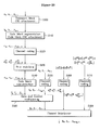
- FIG. 9 illustrates processing of data and control information transmitted through a UL-SCH which is an uplink transport channel.
- a transport block (TB) CRC is attached to the TB of data transmitted to an uplink in step S901.
- the data is to be multiplexed with control information (CQI/PMI or rank indication).
- the CRC attached data is segmented into multiple code blocks (CBs) according to the size of the TB in step S902 and a CB CRC is attached to the CBs in step S903.
- Channel coding is performed upon the CRC-attached CBs in step S904.
- the channel coded data is rate-matched in step S905 and CBs are concatenated in step S906.
- the concatenated CBs are multiplexed with control information in step S907.
- a CRC is attached to CQI/PMI in step S908 and channel coding is performed upon the CRC-attached CQI/PMI in step S909.
- the channel-coded CQI/PMI is rate-matched in step S910 and multiplexed with the data in step S907.
- the channel coding process and the rate matching process are described as separate processes, the channel coding process may include the rate matching process in some cases.
- Rank indication is channel-coded in step S911 separately from the data.
- the channel-coded rank indication is rate-matched in step S912.
- the channel coding process and the rate matching process are described as separate processes, the channel coding process may include the rate matching process in some cases.
- a channel interleaving process is performed upon the multiplexed data, CQI/PMI, and rank indication in step S913.
- Channel coding is performed upon acknowledgement (ACK)/negative acknowledgement (NACK) information in step S914 separately from the data, CQI/PMI, and rank indication.
- ACK acknowledgement
- NACK negative acknowledgement
- the ACK/NACK information is inserted through puncturing a part of the channel-interleaved signal.
- the interleaved signal into which the ACK/NACK information is inserted is transmitted to the uplink after physical resource mapping in step S915.
- the channel coded data, CQI/PMI, and rank indication of specific sizes are converted into data, CQI/PMI, and rank indication having prescribed numbers of symbols or bits transmitted in a physical layer through rate matching.
- the number of symbols or bits transmitted in the physical layer should be present with respect to each of the data, CQI/PMI, and rank indication.
- FIG. 10 illustrates an alternative processing of data and control information transmitted through a UL-SCH which is an uplink transport channel.
- the entire transport block is used to calculate the CRC parity bits.
- the bits in a transport block delivered to layer 1 are denoted by a 0 , a 1 , a 2 , a 3 ,..., a A -1 .
- the parity bits are denoted by p 0 , p 1 , p 2 , p 3 ,..., p L -1 .
- A is the size of the transport block and L is the number of parity bits.
- Code block segmentation and code block CRC attachment are performed after transport block CRC attachment in step 110.
- the bits input to the code block segmentation are denoted by b 0 , b 1 , b 2 , b 3 ,..., b B -1 where B is the number of bits in the transport block (including CRC).
- the bits after code block segmentation are denoted by c r 0 , c r 1 , c r 2 , c r 3 ,..., c r ( K r -1) , where r is the code block number and K r is the number of bits for code block number r.
- Channel coding is performed after code block segmentation and code block CRC in step 120.
- Rate matching is performed on Turbo coded blocks after channel coding in step 130.
- the bits are denoted by e r 0 , e r 1 , e r 2 , e r 3 ,..., e r ( E r -1 ), where r is the coded block number, and where E r is the number of rate matched bits for code block number r .
- Code block concatenation is performed after rate matching in step 140.
- the bits after code block concatenation are denoted by f 0 , f 1 , f 2 , f 3 ,..., f G-1 , where G is the total number of coded bits for transmission excluding the bits used for control transmission, when control information is multiplexed with the UL-SCH transmission.
- the channel coding of the channel quality information is performed with input sequence o 0 , o 1 , o 2 ,..., o o -1 in step 150.
- the output sequence for the channel coding of channel quality information is denoted by q 0 , q 1 , q 2 , q 3 ,..., q Q CQI -1.
- the channel coding of the RI is preformed with input sequence o 0 RI or o 0 RI o 1 RI in step 160.
- o 0 RI and o 0 RI o 1 RI denotes 1-bit RI and denotes 2-bits RI, respectively.
- the channel coding of the HARQ-ACK is performed with input sequence o 0 ACK , o 0 ACK o 1 ACK or o 0 ACK o 1 ACK ⁇ o O ACK - 1 ACK in step 170.
- Each positive acknowledgement (ACK) is encoded as a binary '1' and each negative acknowledgement (NAK) is encoded as a binary '0'.
- HARQ-ACK can consist of 1-bit of information, i.e., o 0 ACK or 2-bits of information, i.e., o 0 ACK o 1 ACK with o 0 ACK corresponding to ACK/NACK bit for codeword 0 and o 1 ACK corresponding to that for codeword 1.
- HARQ-ACK can consist of more than two bits information, i.e. o 0 ACK o 1 ACK ⁇ o O ACK - 1 ACK with O ACK > 2.
- the bit sequence q 0 ACK , q 1 ACK , q 2 ACK , ... , q Q ACK - 1 ACK is obtained by concatenation of multiple encoded HARQ-ACK blocks where Q ACK is the total number of coded bits for all the encoded HARQ-ACK blocks.
- the inputs to the data and control multiplexing are the coded bits of the control information denoted by q 0 , q 1 , q 2 , q 3 ,..., q Q CQI -1 and the coded bits of the UL-SCH denoted by f 0 , f 1 , f 2 , f 3 ,..., f G -1 in step 180.
- H is the total number of coded bits allocated for UL-SCH data and CQI/PMI information.
- the channel interleaving is performed with the output of the data and control multiplexing operation denoted by g 0 , g 1 , g 2 , g 3 ,..., g H' -1 , the encoded rank indication denoted by the q 0 , q 1 , q 2 , q 3 ,...,qQ Q CQI -1 and the encoded HARQ-ACK denoted by q 0 ACK , q 1 ACK , q 2 ACK , ... , q Q ACK - 1 ACK .
- the bits after channel interleaving are denoted by h 0 , h 1 , h 2 ,..., h H+ QRI -1 .
- FIG. 11 illustrates a subframe structure after data and control information are multiplexed.
- the subframe after data, CQI/PMI, rank indication, and ACK/NACK information are appropriately multiplexed in a physical layer is as shown in FIG. 11 .
- the number of transmitted symbols means the number of symbols output through rate matching. Therefore, in the present invention, "the number of transmitted symbols” is referred to as the number of symbols output through rate matching.
- a payload size may be defined as the sum of the size of information (e.g., the size of data, or the size of control information) transmitted from a medium access control (MAC) layer and the size of cyclic redundancy check (CRC) attached arbitrarily to the information in a physical layer.
- the payload of the control information may not include the size of the CRC because the CRC may not be attached to the control information according to the size of the control information before the CRC is attached to the control information. Specifically, if the size of the control information to which the CRC is not attached is smaller than or equal to 11 bits, the CRC is not attached to the control information. In addition, if the size of the control information to which the CRC is not attached is greater than or equal to 12 bits, the CRC is attached to the control information.
- a reference modulation and coding scheme may be defined using the code rate and modulation order of the data.
- An MCS of the control information transmitted together with the data may be estimated using the reference MCS and using offset information of the control information.
- MCS data 1 CodeRate ⁇ ModulationOrder
- a reference MCS is MCS ref
- a payload size of CQI/PMI is N CQI
- a parameter expressing, in dB, an offset value for compensating for a difference between a block error rate of data and a block error rate of CQI/PMI and a difference between a data encoding scheme and a CQI/PMI encoding scheme is ⁇ CQI
- the number M CQI of transmitted symbols of CQI/PMI may be calculated using the following Equation 2.
- ⁇ ⁇ denotes a ceiling function.
- the ceiling function represents a function whose value is the smallest integer not less than a value within the symbol. For example, ⁇ 2.3 ⁇ indicates 3 because the smallest integer not less than 2.3 is 3.
- a payload size of rank indication is N RI
- a parameter expressing, in dB, an offset value for compensating for a difference between a block error rate of data and a block error rate of rank indication and a difference between a data encoding scheme and a rank indication encoding scheme is ⁇ RI
- the number M RI of transmitted symbols of rank indication may be expressed by the following Equation 3.
- the number of transmitted symbols of CQI/PMI and the number of transmitted symbols of rank indication may be calculated.
- the eNB commands transmission of data on an UL-SCH, the eNB informs a UE of only the total number of symbols which can be transmitted when the data and other information are multiplexed, a payload size of the data, and the modulation order of the data. Therefore, agreement between the eNB and the UE is required to calculate the reference MCS.
- the method for calculating the reference MCS uses the code rate and modulation order of data under the assumption that only the data is transmitted on the UL-SCH without transmitting the CQI/PMI or rank indication.
- a reference code rate may be calculated using the following Equation 4.
- CR data N data Q data ⁇ M RE PUSCH
- N data denotes a payload size of data
- Q data denotes a modulation order of data which is a reference modulation order
- M RE PUSCH is the total number of symbols which can be transmitted through a physical channel when transmitting data through the UL-SCH.
- the M RE PUSCH is correspond to M sc PUSCH .
- the reference MCS MCS ref may be calculated using the following Equation 5.
- CR data denotes a reference code rate
- N data denotes a payload size of data
- Q data denotes a modulation order of data which is a reference modulation order
- M RE PUSCH denotes the total number of symbols which can be transmitted through a physical channel when transmitting data through the UL-SCH.
- Equation 4 the payload size N data of data is defined as a value including the CRC but may not include the CRC for simple approximation.
- Example 1-A in the case where data and CQI/PMI are transmitted together
- the reference MCS is calculated using the payload size N data of data.
- the number of finally transmitted symbols of the CQI/PMI may be calculated using the following Equation 6.
- M CQI ⁇ N CQI ⁇ 10 ⁇ CQI 10 ⁇ MCS ref ⁇
- N CQI denotes a payload size of CQI/PMI
- ⁇ CQI denotes a parameter expressing, in dB, an offset value for compensating for a difference between the block error rate of data and the block error rate of CQI/PMI and a difference between a data encoding scheme and a CQI/PMI encoding scheme
- M CQI denotes the number of transmitted symbols of CQI/PMI after rate matching.
- the number M data of transmitted symbols of data may be calculated using the following Equation 7.
- M data M RE PUSCH - M CQI
- M RE PUSCH denotes the total number of symbols which can be transmitted through a physical channel when transmitting data on a UL-SCH. Since the data and CQI/PMI are multiplexed after they are rate-matched, the number of symbols obtained by subtracting M CQI from M RE PUSCH is the number M data of symbols of data.
- Example 1-A in the case where data and rank indication are transmitted together
- the number M RI of transmitted symbols of the rank indication may be calculated using the following Equation 8, similarly to when the data and CQI/PMI are transmitted.
- M RI ⁇ N RI ⁇ 10 ⁇ RI 10 ⁇ MCS ref ⁇
- N RI denotes a payload size of rank indication
- ⁇ RI denotes a parameter expressing, in dB, an offset value for compensating for a difference between the block error rate of data and the block error rate of rank indication and a difference between a data encoding scheme and a rank indication encoding scheme
- M RI denotes the number of transmitted symbols of rank indication.
- M data M RE PUSCH - M RI
- M RE PUSCH denotes the total number of symbols which can be transmitted through a physical channel when transmitting data on a UL-SCH. Since the data and rank indication are multiplexed after they are rate-matched, the number of symbols obtained by subtracting M RI from M RE PUSCH is the number M data of symbols of the data.
- Example 1-A in the case where data CQI/PMI, and rank indication are transmitted together
- M data M RE PUSCH - M CQI - M RI
- a calculation result in the UE and the eNB may vary according to calculation methods of multiplication, division, and 10 ⁇ CQI 10 and 10 ⁇ RI 10 in the UE and eNB.
- a method is proposed for calculating the numbers of transmitted symbols of CQI/PMI and rank indication such that a calculation result of division does not generate a remainder.
- M X ⁇ N X ⁇ 10 ⁇ X 10 ⁇ MCS ref ⁇
- N X denotes a payload size of information X
- ⁇ X denotes a parameter expressing, in dB, an offset value for compensating for a difference between the block error rate of data and the block error rate of the information X and a difference between a data decoding scheme and an information X decoding scheme
- M X denotes the number of transmitted symbols of information X.
- 10 ⁇ X 10 , and MCS ref defined in Equation 5 may be differently calculated in the UE and the eNB.
- the UE and eNB may promise to previously define 10 ⁇ X 10 as a quantized value.
- Table 1 listed below shows a result of quantizing 10 ⁇ X 10 .
- the UE and the eNB may define 10 ⁇ X 10 as a quantized value as shown in Table 1.
- a quantized result of ⁇ X is shown such that a fractional part thereof can be expressed by 6 bits.
- Table 2 and 3 listed below show a result of calculating ⁇ X when the information X is CQI/PMI or rank indication.
- MCS ref may have various values
- the UE and eNB should store large quantities of values in order to define MCS ref as a quantized value between the UE and the eNB.
- division which may generate a non-integer calculation result should be eliminated.
- the number M X of transmitted symbols of information X can be as follows.
- Equation 14 a denominator of MCS ref may be transposed towards M X .
- ⁇ ⁇ Y X ⁇
- an equation for calculating the number of transmitted symbols of information X transmitted through a physical channel to solve a quantization problem may be defined as follows.
- M RE PUSCH denotes the total number of symbols which can be transmitted through a physical channel when transmitting data through a UL-SCH
- N data denotes a payload size of data
- N X denotes the payload size of the information X
- M X denotes the number of transmitted symbols of the information X
- ⁇ X denotes a value of quantizing 10 ⁇ X 10 .
- Equation 15 for calculating the number of transmitted symbols of the information X through a physical channel to solve the quantization problem may be defined as follows. M X ⁇ ⁇ X ⁇ ⁇ N data ⁇ N X ⁇ M RE PUSCH
- M X is the smallest integer satisfying Equation 16.
- the reference MCS is calculated using a code rate and a modulation order of data under the assumption that only the data is transmitted on a UL-SCH without transmitting CQI/PMI or rank indication. Therefore, the reference MCS may not be an accurate value.
- an accurate code rate may not be applied to information (i.e., data, CQI/PMI and rank indication).
- the reference code rate is a code rate of data
- the code rate of data can be determined only when an occupied ratio of CQI/PMI and rank indication among the entire amount of information should be determined.
- the occupied ratio of CQI/PMI and rank indication among the entire amount can be known only when the code rate of data should be determined.
- Example 1-B of the present invention a method is proposed for simultaneously calculating reference code rates of data, CQI/PMI and rank indication in a closed form using the fact that the total number of transmitted symbols is the sum of the numbers of transmitted symbols of the data, CQI/PMI and rank indication on a UL-SCH.
- a reference MCS is an unknown parameter and the numbers of transmitted symbols of CQI/PMI and rank indication are expressed as a function of the reference MCS, since the total number of transmitted symbols of the data, CQI/PMI and rank indication is known, an accurate reference MCS can be obtained.
- Example 1-B in the case where data and CQI/PMI are transmitted together
- the total number of transmitted symbols may be indicated by the sum of the number of transmitted symbols of the CQI/PMI and the number of transmitted symbols of the data. Accordingly, a reference MCS is calculated using the equation for calculating the number of transmitted symbols of the CQI/PMI and the equation for calculating the number of transmitted symbols of the data. Next, the number of transmitted symbols of the data is calculated using the calculated reference MCS and the number of transmitted symbols of the CQI/PMI are calculated.
- the number of transmitted symbols of the data is calculated using the following Equation 17.
- the number of transmitted symbols of the CQI/PMI is expressed by a function of the number of transmitted symbols of the data and a closed-form equation is obtained as shown in the following Equation 18.
- M RE PUSCH ⁇ N CQI ⁇ 10 ⁇ CQI 10 ⁇ M data N data ⁇ + M data
- N data denotes a payload size of data
- M data denotes the number of transmitted symbols of the date
- M RE PUSCH denotes the total number of symbols which can be transmitted through a physical channel
- MCS ref denotes a reference MCS
- N CQI denotes a payload size of CQI/PMI
- ⁇ CQI denotes a parameter expressing, in dB, an offset value for compensating for a difference between a block error rate of data and a block error rate of CQI/PMI and a difference between a data encoding scheme and a CQI/PMI encoding scheme
- M CQI denotes the number of transmitted symbols of CQI/PMI.
- Equation 18 may be replaced with the following Equation 19.
- M RE PUSCH - M data ⁇ N data ⁇ N CQI ⁇ ⁇ CQI ⁇ M data
- ⁇ CQI denotes a value obtained by quantizing 10 ⁇ CQI 10 .
- N data , N CQI , ⁇ CQI , and M RE PUSCH are given, M data is the smallest integer satisfying Equation 19.
- M CQI M RE PUSCH - M data
- Example 1-B in the case where data and rank indication are transmitted together
- the number of transmitted symbols of the rank indication is calculated similarly to the case where only the data and CQI/PMI are transmitted.
- a reference MCS is calculated using the equation for calculating the number of transmitted symbols of the rank indication and the equation for calculating the number of transmitted symbols of the data.
- the number of transmitted symbols of the data is calculated using the calculated reference MCS and the number of transmitted symbols of the rank indication is calculated.
- the number of transmitted symbols of the data is calculated using the following Equation 21.
- the number of transmitted symbols of the rank indication is expressed by a function of the number of transmitted symbols of the data and a closed-form equation is obtained as shown in the following Equation 22.
- M RE PUSCH ⁇ N RI ⁇ 10 ⁇ RI 10 ⁇ M data N data ⁇ + M data
- N data denotes a payload size of data
- M data denotes the number of transmitted symbols of the date
- M RE PUSCH denotes the total number of symbols which can be transmitted through a physical channel
- MCS ref denotes a reference MCS
- N RI denotes a payload size of rank indication
- ⁇ RI denotes a parameter expressing, in dB, an offset value for compensating for a difference between a block error rate of data and a block error rate of rank indication and a difference between a data encoding scheme and a rank indication encoding scheme
- M RI denotes the number of transmitted symbols of rank indication.
- Equation 22 may be replaced with the following Equation 23.
- N data , N RI , ⁇ RI , and M RE PUSCH are given, M data is the smallest integer satisfying Equation 23.
- M RI M RE PUSCH - M data
- Example 1-B in the case where data, CQI/PMI, and rank indication are transmitted together
- the total number of transmitted symbols on a UL-SCH may be indicated by the sum of the number of transmitted symbols of the CQI/PMI, the number of transmitted symbols of the rank indication, and the number of transmitted symbols of the data. Therefore, a reference MCS may be calculated using the equation for calculating the number of transmitted symbols of the CQI/PMI, the equation for calculating the number of transmitted symbols of the rank indication, and the equation for calculating the number of transmitted symbols of the data.
- the number of transmitted symbols of the data may be calculated using the calculated reference MCS and the numbers of transmitted symbols of the CQI/PMI and the rank indication may be calculated.
- the number of transmitted symbols of the data is calculated using the following Equation 25.
- the numbers of transmitted symbols of the CQI/PMI and the rank indication are expressed by a function of the number of transmitted symbols of the data and a closed-form equation is obtained as shown in the following Equation 26.
- N data denotes a payload size of data
- M data denotes the number of transmitted symbols of the date
- M RE PUSCH denotes the total number of symbols which can be transmitted through a physical channel
- MCS ref denotes a reference MCS
- N CQI denotes a payload size of CQI/PMI
- ⁇ CQI denotes a parameter expressing, in dB, an offset value for compensating for a difference between a block error rate of data and a block error rate of CQI/PMI and a difference between a data encoding scheme and a CQI/PMI encoding scheme
- M CQI denotes the number of transmitted symbols of CQI/PMI
- N RI denotes a payload size of rank indication
- ⁇ RI denotes a parameter expressing, in dB, an offset value for compensating for a difference between a block error rate of data and a block error rate of rank indication and a difference between a data
- Equation 26 may be replaced with the following Equation 27.
- ⁇ CQI denotes a value obtained by quantizing 10 ⁇ CQI 10
- ⁇ RI denotes a value obtained by quantizing 10 ⁇ RI 10
- N data , N RI , ⁇ RI , N CQI , ⁇ CQI , and M RE PUSCH are given, M data is the smallest integer satisfying Equation 27.
- M RE PUSCH - M data M CQI + ⁇ N RI ⁇ 10 ⁇ RI 10 ⁇ M CQI N CQI ⁇
- Equation 28 may be replaced with Equation 29.
- M CQI is the smallest integer satisfying Equation 29.
- M RI M RE PUSCH - M data - M CQI
- M RE PUSCH - M data M RI + ⁇ N CQI ⁇ 10 ⁇ CQI 10 ⁇ M RI N RI ⁇
- Equation 31 may be replaced with Equation 32.
- M RI is the smallest integer satisfying Equation 32.
- M CQI M RE PUSCH - M data - M RI
- M CQI or M RI is calculated after calculating M data by the above methods is that values of M data N data , M CQI N CQI , and M RI N RI used as a reference MCS are determined to be almost equal.
- Equation 28 may be expressed by the following Equation 34.
- M RE PUSCH - M data M CQI + ⁇ N RI ⁇ 10 ⁇ RI 10 ⁇ M data N data ⁇
- Equation 34 may be replaced with Equation 35.
- M CQI is the smallest integer satisfying Equation 35.
- M RI M RE PUSCH - M data - M CQI
- Equation 31 may be expressed by the following Equation 37.
- M data , M CQI , and M RI are calculated using Equation 37.
- M RE PUSCH - M data M RI + ⁇ N CQI ⁇ 10 ⁇ CQI 10 ⁇ M data N data ⁇
- Equation 37 may be replaced with the following Equation 38.
- M RI is the smallest integer satisfying Equation 38.
- M CQI M RE PUSCH - M data - M RI
- Example 1-B an order for calculating M data , M RI , and M CQI are as follows.
- Example 1-A the reference MCS does not actually consider an accurate code rate and modulation order of information when data, CQI/PMI, and rank indication are transmitted.
- Example 1-B the method for calculating each information field is complicated.
- Example 1-C a method for expressing the reference MCS as a function of a variety of information is proposed using the fact that an MCS of information most approximates to the reference MCS when utilizing Example 1-B. That is, an approximated equation is used as follows. MCS ref ⁇ M data N data ⁇ M CQI N CQI ⁇ M RI N RI where reference symbol " ⁇ " indicates that a left value and a right vale are approximately equal.
- the reference MCS may be obtained using the following Equation 41 without calculating the number of transmitted symbols of information.
- an approximate reference MCS may be calculated using the fact that the sum of the numbers of transmitted symbols of corresponding information is equal to the total number of symbols transmitted on an UL-SCH.
- the reference MCS since the number of transmitted symbols of corresponding information is determined by an offset value for compensating for a difference in a coding gain or an operation block error rate with respect to data, the reference MCS may be defined as follows.
- the reference MCS is defined as a value obtained by dividing the total number of symbols transmitted on a UL-SCH by the sum of payload sizes of transmitted information.
- offset values for compensating for a difference with the reference MCS of data such as a difference in an encoding scheme, in an operation block error rate, etc. are multiplied to the payload size of corresponding information.
- the numbers of actually transmitted symbols of CQI/PMI and rank indication may be calculated using the following Equation 46.
- N X denotes a payload size of information X
- ⁇ X denotes a parameter expressing, in dB, an offset value for compensating for a difference between a data decoding scheme and an information (X) decoding scheme
- M X denotes the number of transmitted symbols of information X.
- the information X may be CQI/PMI or rank indication.
- the number of transmitted symbols of data is a value obtained by subtracting the numbers of transmitted symbols of CQI/PMI and rank indication from the total number of symbols which can be transmitted.
- CQI/PMI and rank indication may be transmitted on the UL-SCH without transmitting the data.
- an eNB informs a UE of only the total number of symbols transmitted on the UL-SCH. Therefore, a reference MCS is not present.
- a method is proposed for calculating the reference MCS when CQI/PMI and rank indication are transmitted on the UL-SCH.
- Example 2-A a method is proposed for calculating a reference MCS using the code rate and modulation order of CQI/PMI under the assumption that only the CQI/PMI is transmitted on a UL-SCH when the CQI/PMI and rank indication are transmitted.
- the code rate of the CQI/PMI may be defined as follows.
- CR CQI N CQI Q CQI ⁇ M RE PUSCH
- CR CQI denotes a reference code rate
- N CQI denotes a payload size of CQI/PMI
- Q CQI denotes a modulation order of CQI/PMI which is a reference modulation order
- M RE PUSCH denotes the number of symbols which can be transmitted through a physical channel when transmitting CQI/PMI on a UL-SCH.
- the reference MCS may be calculated as follows.
- Example 2-A in the case where CQI/PMI and rank indication are present
- the number of transmitted symbols of the rank indication is calculated first using a reference MCS as shown in the following Equation 52.
- the number of transmitted symbols of the CQI/PMI is calculated by subtracting the number of transmitted symbols of the rank indication from the total number of symbols which can be transmitted through a physical channel.
- N RI denotes a payload size of rank indication
- ⁇ RI denotes a parameter expressing, in dB, an offset value for compensating for a difference between a block error rate of data and a block error rate of rank indication and a difference between a data encoding scheme and a rank indication encoding scheme
- M RI denotes the number of transmitted symbols of rank indication
- M RE PUSCH denotes the total number of symbols which can be transmitted through a physical channel
- M CQI denotes the number of transmitted symbols of CQI/PMI.
- Example 2-A may be differently implemented in a UE and an eNB as described in Examples 1-A and 1-B.
- Equation 52 may be replaced with the following Equation 54.
- Equation 54 M RI ⁇ N CQI ⁇ N RI ⁇ ⁇ RI ⁇ M RE PUSCH
- M RI is the smallest integer satisfying Equation 54.
- M CQI is calculated using Equation 53.
- an accurate code rate is not applied to information (i.e., CQI/PMI and rank indication).
- a reference code rate is a code rate of the CQI/PMI
- the code rate of the CQI/PMI can be determined only when an occupied ratio of rank indication among the entire amount of information should be determined.
- the method described in Example 2-A assumes the code rate of the CQI/PMI in an ideal state as the reference code rate under the assumption that only the CQI/PMI is transmitted.
- Example 2-B a method is proposed for simultaneously calculating reference code rates of CQI/PMI and rank indication in a closed form using the fact that the total number of transmitted symbols is the sum of the numbers of transmitted symbols of the CQI/PMI and rank indication on a UL-SCH.
- a reference MCS is an unknown parameter and the numbers of transmitted symbols of CQI/PMI and rank indication are expressed as a function of the reference MCS, since the total number of transmitted symbols of the CQI/PMI and rank indication is known, an accurate reference MCS can be obtained.
- the total number of symbols transmitted on the UL-SCH may be indicated by the sum of the number of transmitted symbols of the CQI/PMI and the number of transmitted symbols of the rank indication. Accordingly, a reference MCS is calculated using the equation for calculating the number of transmitted symbols of the rank indication and the equation for calculating the number of finally transmitted symbols of the CQI/PMI. The number of transmitted symbols of the rank indication is calculated using the calculated reference MCS and then the number of transmitted symbols of the CQI/PMI is calculated.
- the number of transmitted symbols of the rank indication is calculated using the following Equation 55.
- the number of transmitted symbols of the CQI/PMI is expressed as a function of the number of transmitted symbols of the rank indication and a closed-form equation is obtained as shown in the following Equation 56.
- M RE PUSCH M CQI + M RI
- N RI denotes a payload size of rank indication
- ⁇ RI denotes a parameter expressing, in dB, an offset value for compensating for a difference between a block error rate of data and a block error rate of rank indication and a difference between a data encoding scheme and a rank indication encoding scheme
- M RI denotes the number of transmitted symbols of rank indication
- M RE PUSCH denotes the total number of symbols which can be transmitted through a physical channel
- M CQI denotes the number of transmitted symbols of CQI/PMI.
- Equation 56 may be replaced with the following Equation 57.
- the number of transmitted symbols of the rank indication is calculated using the following Equation 59.
- the number of transmitted symbols of the CQI/PMI is a calculated by subtracting the number of transmitted symbols of the rank indication from the total number of symbols transmitted on the UL-SCH.
- N X denotes a payload size of information X
- ⁇ X denotes a parameter expressing, in dB, an offset value for compensating for a difference between a data decoding scheme and an information (X) decoding scheme
- M X denotes the number of transmitted symbols of information X.
- the information X may correspond to the rank indication.
- ACK/NACK information is inserted through puncturing multiplexed data, CQI/PMI, and rank indication and thus a code rate of the information can be changed.
- an eNB does not always know whether or not a UE transmits ACK/NACK information, the number of transmitted symbols of ACK/NACK information is independently calculated using a reference MCS after the number of occupied symbols on a UL-SCH.
- N A / N denotes a payload size of ACK/NACK information
- ⁇ A / N denotes a parameter expressing, in dB, an offset value for compensating for a difference between a block error rate of data and a block error rate of ACK/NACK information and a difference between a data encoding scheme and a ACK/NACK information encoding scheme
- M A / N denotes the number of finally transmitted symbols of ACK/NACK information.
- a method for calculating the number of transmitted symbols of ACK/NACK information through a physical channel is as follows.
- ⁇ A / N denotes a value obtained by quantizing 10 ⁇ A / N 10 .
- M A / N is the smallest integer satisfying Equation 61.
- ACK/NACK information and rank indication transmitted on a UL-SCH always use quadrature phase shift keying (QPSK) or binary phase shift keying (BPSK) modulation.
- QPSK quadrature phase shift keying
- BPSK binary phase shift keying
- the ACK/NACK and rank indication may use only 4 outermost coordinates (2 outermost coordinates when BPSK is used) of a modulation constellation of the data or CQI/PMI.
- FIG. 12 illustrates an example of modulation constellation coordinates used by ACK/NACK information and rank indication when data and CQI/PMI use a 16 quadrature amplitude modulation (QAM) scheme.
- FIG. 13 illustrates an example of modulation constellation coordinates used by ACK/NACK information and rank indication when data and CQI/PMI use a 64 QAM scheme.
- M A / N and M RI are calculated using the above-described Embodiments 1-A, 1-B, 2-A, and 2-B.
- the modulation order of the data or CQI/PMI is 16 QAM
- the maximum numbers of transmissible symbols of rank indication and ACK/NACK information may be limited.
- M A / N which is the numbers of transmitted symbols of the ACK/NACK information
- M A / N is set to the maximum numbers of transmissible symbols of the ACK/NACK information.
- M RI which is the numbers of transmitted symbols of the ACK/NACK information
- M RI is set to the maximum numbers of transmissible symbols of the rank indication.
- the maximum numbers or values of M A / N and M RI may be 12 ⁇ N RB ⁇ 4.
- N RB denotes the number of resource blocks (RBs) transmitted through a physical uplink shared channel (PUSCH). If one RB is transmitted through the PUSCH, the maximum values of M A / N and M RI are 48.
- the number of transmitted symbols of the rank indication may be calculated last according to circumstances. Then it is confirmed whether the number M RI of transmitted symbols of the rank indication exceeds a maximum transmissible value. If M RI exceeds the maximum value, M RI is limited to the maximum value and symbols of the data or CQI/PMI corresponding to a difference between the calculated M RI and the maximum transmissible value are further transmitted.
- a reference code rate greater than 1 may be set or calculated. If the reference code rate is greater than 1, CQI/PMI, rank indication, and ACK/NACK information are not decoded in an eNB and a UE may transmit unnecessary information. In this case, the number of transmitted symbols of the CQI/PMI, rank indication, and ACK/NACK information may be set to 0 and only data may be transmitted.
- an eNB may not generate a circumstance having a code rate greater than 1. If a UE senses such a circumstance, it is determined that the eNB has made a mistake or the UE has read different control information so that no information may be transmitted to the uplink.
- Retransmission may be commended by eNB or may be performed via a predetermined schedule.
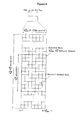
- FIG. 14 shows a HARQ process for explaining data retransmission. As shown in FIG. 14 , it is configured that maximum process is set to be 8 processes and maximum retransmission time is set to be 4. In each process, when the UE receives UL_Grant from the eNB at n th subframe timing, the UE start to transmit data in n+4 th subframe.
- Process 1 if the UE does not receive ACK from the eNB during 3 times retransmission of data (e.g., denoted by '1' in FIG. 14 ) stored in a buffer after starting to transmit data in a n+4 th subframe, the UE performs buffer flush, reconstructs the data and transmits the reconstructed data (e.g., denoted by 1 re in FIG. 14 ).
- Process 2 is an identical case to the process 1.
- Process 3 if the UE receives ACK from the eNB after retransmitting data (e.g., dented by 3 in FIG. 14 ) 2 times, the UE transmits new data (e.g., denoted by 3' in FIG.
- Process 3 if the UE does not receive ACK from the eNB after transmitting the new data, the UE retransmits the new data at 5 th transmission timing.
- Processes 4 to 6 can be explained as described above. In addition, each of processes 1 to 8 is operated independently.
- the communication system when the communication system operates such that the initial data packet is transmitted without errors with a probability of 90%, the system does not encounter any problem even when the data packet is re-transmitted at a code rate higher than a code rate of the initial data packet. Transmitting a data packet at a high code rate means that less physical transmission resources are used than during the initial transmission of the data packet.
- a method for calculating a reference MCS using a packet size of data and the total number of symbols which can be transmitted through a PUSCH and a method for calculating the number of transmitted symbols of CQI/PMI and rank indication using the reference MCS have been proposed.
- CQI/PMI and/or rank indication may be multiplexed with re-transmitted data and then may be transmitted.
- FIG. 15 is a diagram explaining a use relationship of a reference MCS during re-transmission of data. As illustrated in FIC. 15, while data is re-transmitted through a PUSCH, a method for calculating the numbers of transmitted symbols of CQI/PMI, rank indication, and ACK/NACK information is proposed using a code rate used during the initial transmission of data.
- a reference MCS in the following Equation 62 to calculate the number of transmitted symbols of information X employs a reference MCS used when data is initially transmitted.
- MCS ref denotes a reference MCS when the data is initially transmitted
- N x denotes a payload size of information X
- ⁇ x denotes a parameter expressing, in dB, an offset value for compensating for a difference between the decoding scheme of data and the decoding scheme of the information X
- M x denotes the number of transmitted symbols of information X.
- the information X can be CQI/PMI, rank indication or ACK/NACK information.
- the equation 62 can be expressed by the following equation 63.
- Q ' is the number of transmitted symbols of the control information (e.g., CQI/PMI, rank indication or ACK/NACK information) when the data is retransmitted
- O is the payload size of the control information when the data is retransmitted.
- N symb PUSCH - initial is a number of SC-FDMA symbols per subframe for Physical Uplink Shared Channel (PUSCH) transmission when the data is initially transmitted and M sc PUSCH - initial is a scheduled bandwidth PUSCH transmission when the data is initially transmitted.
- M sc PUSCH - initial ⁇ N symb PUSCH - initial is the total number of transmissible symbols of Physical Uplink Shared Channel (PUSCH) when the data is initially transmitted.
- ⁇ offset PUSCH is the offset value.
- K r is the payload size of the data when the data is initially transmitted, r is code block number of the data before channel coding, Kr is a number of bits in code block number r, and C is a total number of code blocks.
- RV redundancy version
- a function of each module of a UE during re-transmission of the data is as follows.
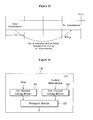
- FIG. 16 is a block diagram of a UE according to an exemplary embodiment of the present invention.
- a UE 130 includes a first channel coding module 131, a second channel coding module 132, and a transport module 133.
- the UE 130 may further include modules such as a multiplexing module, a transport module, and an interleaving module but these are omitted for convenience of description.
- the first channel coding module 131 performs channel coding upon data to be retransmitted.
- the second channel coding module 132 performs channel coding upon control information.
- the second channel coding module 132 calculates the number of transmitted symbols of the control channel by using the Equation 63.
- the transport module 133 performs channel interleaving upon the first channel-coded data and the second channel-coded control information and transmits the interleaved uplink signal to an uplink.
- a code rate for stably transmitting the CQI/PMI and/or rank indication during re-transmission of data can be set.
- an uplink signal including the data and control information can be transmitted by accurately calculating code rates of the data and control information.
- the present invention may be applied to a UE, an eNB or other equipment of a radio mobile communication system. If applied to an eNB, the eNB performs a deinterleaving and decoding operation to derive the signal from the encoded/interleaved signal sent by the UE.
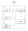
- FIG. 17 is a block diagram showing constitutional elements of a device 50, that can be either a UE or an eNB, and that can perform the methods described above.
- Device 50 includes a processor 51, a memory 52, a radio frequency (RF) unit 53, a display unit 54, and a user interface unit 55. Layers of the radio interface protocol are implemented in the processor 51.
- the processor 51 provides the control plane and the user plane. The function of each layer can be implemented in the processor 51.
- the processor 51 may also include a contention resolution timer.
- the memory 52 is coupled to the processor 51 and stores an operating system, applications, and general files.
- the display unit 54 displays a variety of information and may use a well-known element such as a liquid crystal display (LCD), an organic light emitting diode (OLED), etc.
- the user interface unit 55 can be configured with a combination of well-known user interfaces such as a keypad, a touch screen, etc.
- the RF unit 53 is coupled to the processor 51 and transmits and/or receives radio signals.
- the eNB refers to a terminal node of a network communicating directly with the UE.
- a specific operation described as being performed by the eNB may be performed by an upper node of the eNB.
- the eNB or any other network nodes may perform various operations for communication with the UE in a network comprised of a plurality of network nodes including the eNB.
- the term 'eNB' may be replaced with the term 'fixed station', 'Node B', 'access point', etc.
- the term 'UE' corresponds to a mobile station (MS) and the MS may be replaced with the term 'subscriber station' (SS), 'mobile subscriber station' (MSS), 'mobile terminal', etc.
- the UE employed in the present invention may be a personal digital assistant (PDA), a cellular phone, a personal communication service (PCS) phone, a global system for mobile (GSM) phone, a wideband code division multiple access (wide CDMA) phone, a mobile broadband system (MBS) phone, etc.
- PDA personal digital assistant
- PCS personal communication service
- GSM global system for mobile
- WCS mobile broadband system
- the embodiments of the present invention may be implemented by various means, for example, hardware, firmware, software, or a combination thereof.
- ASICs application specific integrated circuits
- DSPs digital signal processors
- DSPDs digital signal processing devices
- PLDs programmable logic devices
- FPGAs field programmable gate arrays
- methods according to the embodiments of the present invention may be implemented in the form of modules, procedures, functions, etc. which perform the above-described functions or operations.
- Software code may be stored in a memory unit so as to be driven by a processor.
- the memory unit is located at the interior or exterior of the processor and may transmit data to and receive data from the processor via various known means.
Landscapes
- Engineering & Computer Science (AREA)
- Computer Networks & Wireless Communication (AREA)
- Signal Processing (AREA)
- Multimedia (AREA)
- Business, Economics & Management (AREA)
- General Business, Economics & Management (AREA)
- Quality & Reliability (AREA)
- Mobile Radio Communication Systems (AREA)
- Detection And Prevention Of Errors In Transmission (AREA)
- Time-Division Multiplex Systems (AREA)
- Radar Systems Or Details Thereof (AREA)
Priority Applications (1)
| Application Number | Priority Date | Filing Date | Title |
|---|---|---|---|
| EP11157996.7A EP2328294B1 (en) | 2008-05-27 | 2009-05-26 | Method and device for transmitting uplink signal including control information via uplink channel |
Applications Claiming Priority (4)
| Application Number | Priority Date | Filing Date | Title |
|---|---|---|---|
| US5606808P | 2008-05-27 | 2008-05-27 | |
| US7467908P | 2008-06-23 | 2008-06-23 | |
| KR1020090033078A KR100925444B1 (ko) | 2008-05-27 | 2009-04-16 | 상향링크 채널을 통해 데이터와 제어 정보를 포함하는 상향링크 신호를 전송하는 방법 |
| EP09161114A EP2129030B1 (en) | 2008-05-27 | 2009-05-26 | Method and device for transmitting an uplink signal including data and control information |
Related Parent Applications (2)
| Application Number | Title | Priority Date | Filing Date |
|---|---|---|---|
| EP09161114.5 Division | 2009-05-26 | ||
| EP09161114A Division EP2129030B1 (en) | 2008-05-27 | 2009-05-26 | Method and device for transmitting an uplink signal including data and control information |
Related Child Applications (3)
| Application Number | Title | Priority Date | Filing Date |
|---|---|---|---|
| EP11157996.7A Division EP2328294B1 (en) | 2008-05-27 | 2009-05-26 | Method and device for transmitting uplink signal including control information via uplink channel |
| EP11157996.7A Division-Into EP2328294B1 (en) | 2008-05-27 | 2009-05-26 | Method and device for transmitting uplink signal including control information via uplink channel |
| EP11157996.7 Division-Into | 2011-03-14 |
Publications (3)
| Publication Number | Publication Date |
|---|---|
| EP2242201A2 EP2242201A2 (en) | 2010-10-20 |
| EP2242201A3 EP2242201A3 (en) | 2011-06-15 |
| EP2242201B1 true EP2242201B1 (en) | 2014-09-10 |
Family
ID=41666414
Family Applications (3)
| Application Number | Title | Priority Date | Filing Date |
|---|---|---|---|
| EP10171033.3A Active EP2242201B1 (en) | 2008-05-27 | 2009-05-26 | Method and device for transmitting uplink signal including data and control information via uplink channel |
| EP11157996.7A Active EP2328294B1 (en) | 2008-05-27 | 2009-05-26 | Method and device for transmitting uplink signal including control information via uplink channel |
| EP09161114A Active EP2129030B1 (en) | 2008-05-27 | 2009-05-26 | Method and device for transmitting an uplink signal including data and control information |
Family Applications After (2)
| Application Number | Title | Priority Date | Filing Date |
|---|---|---|---|
| EP11157996.7A Active EP2328294B1 (en) | 2008-05-27 | 2009-05-26 | Method and device for transmitting uplink signal including control information via uplink channel |
| EP09161114A Active EP2129030B1 (en) | 2008-05-27 | 2009-05-26 | Method and device for transmitting an uplink signal including data and control information |
Country Status (13)
| Country | Link |
|---|---|
| US (5) | US7912133B2 (ja) |
| EP (3) | EP2242201B1 (ja) |
| JP (4) | JP5329651B2 (ja) |
| KR (1) | KR100925444B1 (ja) |
| CN (2) | CN102047578B (ja) |
| AT (1) | ATE484897T1 (ja) |
| AU (1) | AU2009252060B2 (ja) |
| CA (1) | CA2725684C (ja) |
| DE (1) | DE602009000274D1 (ja) |
| ES (1) | ES2525555T3 (ja) |
| GB (1) | GB2458827B (ja) |
| RU (1) | RU2462815C2 (ja) |
| WO (1) | WO2009145525A2 (ja) |
Families Citing this family (60)
| Publication number | Priority date | Publication date | Assignee | Title |
|---|---|---|---|---|
| US8386878B2 (en) * | 2007-07-12 | 2013-02-26 | Samsung Electronics Co., Ltd. | Methods and apparatus to compute CRC for multiple code blocks |
| US8281201B2 (en) | 2008-02-03 | 2012-10-02 | Lg Electronics Inc. | Method and apparatus for supporting HARQ |
| US20090196366A1 (en) * | 2008-02-04 | 2009-08-06 | Zukang Shen | Transmission of Uplink Control Information with Data in Wireless Networks |
| US8737517B2 (en) | 2008-03-26 | 2014-05-27 | Qualcomm Incorporated | Scrambling and modulation to constrain the constellation size of ACK/NAK transmission on the data channel |
| CN101267679B (zh) * | 2008-04-26 | 2013-03-27 | 中兴通讯股份有限公司 | 一种用于映射物理随机接入信道的方法 |
| KR100925444B1 (ko) | 2008-05-27 | 2009-11-06 | 엘지전자 주식회사 | 상향링크 채널을 통해 데이터와 제어 정보를 포함하는 상향링크 신호를 전송하는 방법 |
| US8072899B2 (en) | 2008-07-02 | 2011-12-06 | Interdigital Patent Holdings, Inc. | Method and apparatus for measuring and reporting a rank and a precoding matrix for multiple-input multiple-output communication |
| CN101394251A (zh) * | 2008-07-23 | 2009-03-25 | 中兴通讯股份有限公司 | 秩指示信息的发送方法和装置 |
| KR101638900B1 (ko) * | 2008-08-05 | 2016-07-12 | 엘지전자 주식회사 | 무선 통신 시스템에서 하향링크 멀티 캐리어에 대한 제어정보를 전송하는 방법 |
| KR101253190B1 (ko) | 2008-08-08 | 2013-04-10 | 엘지전자 주식회사 | 무선 통신 시스템에서 채널 품질 정보 보고 방법 및 상기 채널 품질 정보에 따라 무선 자원을 할당하는 방법 |
| US8483076B2 (en) * | 2008-08-18 | 2013-07-09 | Qualcomm Incorporated | A-periodic PUCCH transmission on PUSCH |
| US8264992B2 (en) * | 2008-11-26 | 2012-09-11 | Research In Motion Limited | Control information feedback over the long-term evolution physical uplink shared channel |
| EP3672123B1 (en) * | 2008-12-02 | 2021-02-03 | Sun Patent Trust | Encoding ratio setting method and radio communication device |
| WO2010085591A2 (en) * | 2009-01-23 | 2010-07-29 | Interdigital Patent Holdings, Inc. | Derivation of lte system information retransmission redundancy versions |
| KR101649397B1 (ko) | 2009-03-16 | 2016-08-19 | 인터디지탈 패튼 홀딩스, 인크 | 반송파 집적 및 클러스터된 dft를 갖는 업링크 mimo용 데이터 및 제어 다중화 |
| WO2010109521A1 (ja) * | 2009-03-25 | 2010-09-30 | 富士通株式会社 | 無線通信システム、移動局装置、基地局装置、及び無線通信システムにおける無線通信方法 |
| US9236985B2 (en) * | 2009-04-23 | 2016-01-12 | Qualcomm Incorporated | Method and apparatus for control and data multiplexing in a MIMO communication system |
| AU2010240406B2 (en) | 2009-04-24 | 2014-08-21 | Sharp Kabushiki Kaisha | Wireless communication system, communication apparatus, communication method and communication program |
| US8396170B2 (en) * | 2009-07-30 | 2013-03-12 | Qualcomm Incorporated | Utilization of a known portion of a payload to decode a payload having a known and an unknown portion |
| US8442022B2 (en) | 2009-10-01 | 2013-05-14 | Electronic And Telecommunications Research Institute | Method of transmitting control information using physical uplink shared channel region in MIMO antenna system |
| CN102013938B (zh) | 2009-12-07 | 2012-07-04 | 华为技术有限公司 | 传输上行控制信息的方法和装置 |
| KR101148727B1 (ko) * | 2009-12-15 | 2012-05-21 | 한국전자통신연구원 | 제어 정보를 기지국으로 전송하는 데이터 전송 시스템 |
| US9270427B2 (en) | 2010-01-11 | 2016-02-23 | Futurewei Technologies, Inc. | System and method for multiplexing control and data channels in a multiple input, multiple output communications system |
| CN102082625B (zh) * | 2010-01-11 | 2014-10-22 | 电信科学技术研究院 | 一种反馈多载波信道信息的方法及装置 |
| KR101785656B1 (ko) * | 2010-03-04 | 2017-10-16 | 엘지전자 주식회사 | Ack/nack 신호를 전송하는 방법 및 이를 위한 장치 |
| ES2681020T3 (es) * | 2010-03-22 | 2018-09-11 | Samsung Electronics Co., Ltd | Control de multiplexación e información de datos procedentes de un equipo de usuario en un canal físico de datos |
| WO2011118943A2 (ko) * | 2010-03-22 | 2011-09-29 | 엘지전자 주식회사 | 제어 정보를 전송하는 방법 및 이를 위한 장치 |
| KR101813031B1 (ko) | 2010-04-13 | 2017-12-28 | 엘지전자 주식회사 | 상향링크 신호를 전송하는 방법 및 이를 위한 장치 |
| US20110255631A1 (en) * | 2010-04-20 | 2011-10-20 | Samsung Electronics Co., Ltd. | Methods and apparatus for fast synchronization using tail biting convolutional codes |
| JP5276047B2 (ja) * | 2010-04-30 | 2013-08-28 | 株式会社エヌ・ティ・ティ・ドコモ | 移動端末装置 |
| US9100155B2 (en) * | 2010-05-03 | 2015-08-04 | Qualcomm Incorporated | Method and apparatus for control and data multiplexing in wireless communication |
| PL3565153T3 (pl) | 2010-05-11 | 2022-12-12 | Electronics And Telecommunications Research Institute | Sposób nadawania informacji o randze kanału zstępującego przez fizyczny, współdzielony kanał wstępujący |
| CN103053121B (zh) * | 2010-06-08 | 2015-08-05 | 三星电子株式会社 | 复用来自用户设备的控制和数据信息的方法及装置 |
| US8989156B2 (en) | 2010-06-18 | 2015-03-24 | Sharp Kabushiki Kaisha | Selecting a codeword and determining a symbol length for uplink control information |
| US8634345B2 (en) | 2010-06-18 | 2014-01-21 | Sharp Laboratories Of America, Inc. | Uplink control information (UCI) multiplexing on the physical uplink shared channel (PUSCH) |
| AU2011270584B2 (en) | 2010-06-21 | 2014-03-13 | Sun Patent Trust | Terminal apparatus and communication method thereof |
| KR101362116B1 (ko) | 2010-07-29 | 2014-02-12 | 한국전자통신연구원 | 사용자 기기 모뎀을 위한 물리 상향링크 공유 채널 인코더 및 그것의 인코딩 방법 |
| US9236977B2 (en) * | 2010-10-04 | 2016-01-12 | Qualcomm Incorporated | Method and apparatus for PUCCH and PUSCH encoding |
| US9526089B2 (en) * | 2010-10-27 | 2016-12-20 | Lg Electronics Inc. | Method for transmitting control information in a wireless communication system, and device therefor |
| EP3447951A1 (en) * | 2010-11-10 | 2019-02-27 | ZTE Corporation | Method and terminal for transmitting uplink control information and method and apparatus for determining the number of coded symbol |
| KR101923440B1 (ko) * | 2011-02-15 | 2018-11-29 | 엘지전자 주식회사 | 무선접속시스템에서 채널품질제어정보 전송방법 및 장치 |
| US8780789B2 (en) * | 2011-02-16 | 2014-07-15 | Telefonaktiebolaget L M Ericsson (Publ) | Methods and nodes related to coding of channel status information (CSI) payload |
| US9191176B2 (en) * | 2011-02-23 | 2015-11-17 | Lg Electronics Inc. | Method for coding and transmitting uplink control information in a wireless access system |
| US20130083746A1 (en) * | 2011-09-30 | 2013-04-04 | Interdigital Patent Holdings, Inc. | Method and apparatus for allocating resources for an enhanced physical hybrid automatic repeat request indicator channel |
| USRE49468E1 (en) * | 2012-10-24 | 2023-03-21 | Samsung Electronics Co., Ltd | Method and apparatus for transmitting and receiving common channel information in wireless communication system |
| JP2017512438A (ja) | 2014-03-04 | 2017-05-18 | エルジー エレクトロニクス インコーポレイティド | 探索信号を受信するために制御情報を受信する方法及び装置 |
| CA2967281C (en) | 2014-12-08 | 2023-01-31 | Lg Electronics Inc. | Method for transmitting uplink control information and device therefor |
| JP6121061B2 (ja) * | 2015-03-09 | 2017-04-26 | 三菱電機株式会社 | 送信装置 |
| US10348466B2 (en) | 2015-11-03 | 2019-07-09 | Qualcomm Incorporated | Transport block segmentation and signaling |
| US10419176B2 (en) | 2015-11-12 | 2019-09-17 | Qualcomm Incorporated | Methods and apparatus for transmitting in-band control information in wireless communication |
| US10973018B2 (en) * | 2015-11-23 | 2021-04-06 | Qualcomm Incorporated | Wireless resource blocks with integrated control and data |
| US10142074B2 (en) * | 2016-11-03 | 2018-11-27 | Qualcomm Incorporated | Techniques and apparatuses for common uplink burst |
| AU2017354782A1 (en) * | 2016-11-04 | 2019-05-23 | Telefonaktiebolaget Lm Ericsson (Publ) | PT-RS configuration depending on scheduling parameters |
| ES2837124T3 (es) | 2016-12-19 | 2021-06-29 | Ericsson Telefon Ab L M | Sistemas y métodos para conmutar osciladores de cristal de referencia para un transceptor de un dispositivo inalámbrico |
| US10225046B2 (en) | 2017-01-09 | 2019-03-05 | At&T Intellectual Property I, L.P. | Adaptive cyclic redundancy check for uplink control information encoding |
| WO2018141903A1 (en) * | 2017-02-03 | 2018-08-09 | Telefonaktiebolaget Lm Ericsson (Publ) | Dynamic mcs offset for short tti |
| CN112994844B (zh) | 2017-06-23 | 2023-02-14 | 华为技术有限公司 | 一种信道编码方法、数据接收方法及相关设备 |
| US10986631B2 (en) * | 2017-06-27 | 2021-04-20 | Apple Inc. | Uplink control information (UCI) transmission and hybrid automatic repeat request (HARQ) process identification for grant-free physical uplink shared channel (PUSCH) |
| JP7058087B2 (ja) * | 2017-07-03 | 2022-04-21 | シャープ株式会社 | 端末装置、基地局装置、および、通信方法 |
| US20210105084A1 (en) * | 2019-10-02 | 2021-04-08 | Qualcomm Incorporated | Selection of modulation and coding schemes for control information multiplexed with data |
Family Cites Families (25)
| Publication number | Priority date | Publication date | Assignee | Title |
|---|---|---|---|---|
| FR2659148B1 (fr) | 1990-03-01 | 1993-04-16 | Commissariat Energie Atomique | Procede de connexion entre une fibre optique et un microguide optique. |
| DE69833199T2 (de) * | 1997-08-01 | 2006-09-07 | Ntt Mobile Communications Network Inc. | Datenfolgegenerator, sender, informationsdatendekoder, empfänger, sender-empfänger, datenfolgegenerationsverfahren, informationsdatendekodierungsverfahren, und aufzeichnungsmedium |
| US20020071407A1 (en) * | 2000-07-08 | 2002-06-13 | Samsung Electronics Co., Ltd. | HARQ method in a CDMA mobile communication system |
| US6980540B1 (en) * | 2000-08-16 | 2005-12-27 | Lucent Technologies Inc. | Apparatus and method for acquiring an uplink traffic channel, in wireless communications systems |
| KR20030011136A (ko) * | 2003-01-09 | 2003-02-06 | 백정광 | 건설 폐기물 처리 방법 |
| CN100583718C (zh) * | 2004-06-09 | 2010-01-20 | 三星电子株式会社 | 移动电信系统中用于数据传输的方法和设备 |
| KR101061116B1 (ko) * | 2004-09-15 | 2011-08-31 | 엘지전자 주식회사 | 이동통신 시스템에서 상향링크 제어정보 전송 방법 및수신측에서의 제어정보의 복호 방법 |
| JP4616070B2 (ja) * | 2005-05-02 | 2011-01-19 | 株式会社エヌ・ティ・ティ・ドコモ | 伝送速度制御方法及び移動局 |
| KR100785789B1 (ko) * | 2005-12-07 | 2007-12-13 | 한국전자통신연구원 | 가상 홈 게이트웨이를 포함한 통합관리 시스템 및 그시스템을 이용한 긴급상황 처리 방법 |
| US9143288B2 (en) * | 2006-07-24 | 2015-09-22 | Qualcomm Incorporated | Variable control channel for a wireless communication system |
| EP2051426A1 (en) * | 2006-08-08 | 2009-04-22 | Panasonic Corporation | Multiantenna radio transmitting apparatus and multiantenna radio transmitting method |
| EP2528260A3 (en) * | 2006-10-30 | 2014-07-30 | InterDigital Technology Corporation | Method and apparatus for encoding and decoding high speed shared control channel data |
| MY148998A (en) * | 2007-04-30 | 2013-06-28 | Interdigital Tech Corp | Feedback signaling error detection and checking in mimo wireless communication systems |
| US8031688B2 (en) | 2007-06-11 | 2011-10-04 | Samsung Electronics Co., Ltd | Partitioning of frequency resources for transmission of control signals and data signals in SC-FDMA communication systems |
| US8189559B2 (en) * | 2007-07-23 | 2012-05-29 | Samsung Electronics Co., Ltd. | Rate matching for hybrid ARQ operations |
| JP5561765B2 (ja) | 2007-08-10 | 2014-07-30 | 日本電気株式会社 | 無線通信方法、無線通信システム、基地局、移動局、及びプログラム |
| US8630184B2 (en) * | 2007-08-15 | 2014-01-14 | Qualcomm Incorporated | Uplink control channel format |
| US20090047984A1 (en) * | 2007-08-16 | 2009-02-19 | Sridhar Gollamudi | Method for selecting a serving carrier in a multi-carrier system |
| KR101531416B1 (ko) * | 2007-09-13 | 2015-06-24 | 옵티스 셀룰러 테크놀로지, 엘엘씨 | 상향링크 신호 전송 방법 |
| JP5022859B2 (ja) | 2007-10-22 | 2012-09-12 | 株式会社エヌ・ティ・ティ・ドコモ | 伝送速度制御方法、移動通信システム及び無線基地局 |
| US8281201B2 (en) * | 2008-02-03 | 2012-10-02 | Lg Electronics Inc. | Method and apparatus for supporting HARQ |
| KR100925444B1 (ko) * | 2008-05-27 | 2009-11-06 | 엘지전자 주식회사 | 상향링크 채널을 통해 데이터와 제어 정보를 포함하는 상향링크 신호를 전송하는 방법 |
| US8422439B2 (en) * | 2008-12-31 | 2013-04-16 | Motorola Mobility Llc | Apparatus and method for communicating control information over a data channel in the absence of user data |
| US8625554B2 (en) * | 2009-01-30 | 2014-01-07 | Samsung Electronics Co., Ltd. | System and method for uplink data and control signal transmission in MIMO wireless systems |
| US8989156B2 (en) * | 2010-06-18 | 2015-03-24 | Sharp Kabushiki Kaisha | Selecting a codeword and determining a symbol length for uplink control information |
-
2009
- 2009-04-16 KR KR1020090033078A patent/KR100925444B1/ko active IP Right Grant
- 2009-05-22 CN CN2009801193009A patent/CN102047578B/zh active Active
- 2009-05-22 CN CN201110226084.7A patent/CN102355337B/zh active Active
- 2009-05-22 RU RU2010143008/07A patent/RU2462815C2/ru active
- 2009-05-22 AU AU2009252060A patent/AU2009252060B2/en active Active
- 2009-05-22 WO PCT/KR2009/002709 patent/WO2009145525A2/en active Application Filing
- 2009-05-22 CA CA2725684A patent/CA2725684C/en active Active
- 2009-05-22 JP JP2011510430A patent/JP5329651B2/ja active Active
- 2009-05-26 US US12/472,162 patent/US7912133B2/en active Active
- 2009-05-26 ES ES10171033.3T patent/ES2525555T3/es active Active
- 2009-05-26 EP EP10171033.3A patent/EP2242201B1/en active Active
- 2009-05-26 DE DE602009000274T patent/DE602009000274D1/de active Active
- 2009-05-26 EP EP11157996.7A patent/EP2328294B1/en active Active
- 2009-05-26 EP EP09161114A patent/EP2129030B1/en active Active
- 2009-05-26 AT AT09161114T patent/ATE484897T1/de not_active IP Right Cessation
- 2009-05-27 GB GB0909099A patent/GB2458827B/en active Active
-
2011
- 2011-02-08 US US13/023,351 patent/US8406148B2/en active Active
-
2013
- 2013-01-15 US US13/742,204 patent/US9113456B2/en active Active
- 2013-01-15 US US13/742,221 patent/US9125192B2/en active Active
- 2013-07-24 JP JP2013153761A patent/JP5625092B2/ja active Active
-
2014
- 2014-09-29 JP JP2014198146A patent/JP5844446B2/ja active Active
-
2015
- 2015-08-03 US US14/816,664 patent/US9504025B2/en active Active
- 2015-11-18 JP JP2015225381A patent/JP6001753B2/ja active Active
Also Published As
Similar Documents
| Publication | Publication Date | Title |
|---|---|---|
| EP2242201B1 (en) | Method and device for transmitting uplink signal including data and control information via uplink channel | |
| US10491339B2 (en) | Method and apparatus for supporting HARQ | |
| EP4243290A2 (en) | Circular buffer rate matching for polar codes |
Legal Events
| Date | Code | Title | Description |
|---|---|---|---|
| PUAI | Public reference made under article 153(3) epc to a published international application that has entered the european phase |
Free format text: ORIGINAL CODE: 0009012 |
|
| 17P | Request for examination filed |
Effective date: 20100728 |
|
| AC | Divisional application: reference to earlier application |
Ref document number: 2129030 Country of ref document: EP Kind code of ref document: P |
|
| AK | Designated contracting states |
Kind code of ref document: A2 Designated state(s): AT BE BG CH CY CZ DE DK EE ES FI FR GB GR HR HU IE IS IT LI LT LU LV MC MK MT NL NO PL PT RO SE SI SK TR |
|
| PUAL | Search report despatched |
Free format text: ORIGINAL CODE: 0009013 |
|
| AK | Designated contracting states |
Kind code of ref document: A3 Designated state(s): AT BE BG CH CY CZ DE DK EE ES FI FR GB GR HR HU IE IS IT LI LT LU LV MC MK MT NL NO PL PT RO SE SI SK TR |
|
| 17Q | First examination report despatched |
Effective date: 20120213 |
|
| GRAP | Despatch of communication of intention to grant a patent |
Free format text: ORIGINAL CODE: EPIDOSNIGR1 |
|
| INTG | Intention to grant announced |
Effective date: 20140331 |
|
| GRAS | Grant fee paid |
Free format text: ORIGINAL CODE: EPIDOSNIGR3 |
|
| GRAA | (expected) grant |
Free format text: ORIGINAL CODE: 0009210 |
|
| AC | Divisional application: reference to earlier application |
Ref document number: 2129030 Country of ref document: EP Kind code of ref document: P |
|
| AK | Designated contracting states |
Kind code of ref document: B1 Designated state(s): AT BE BG CH CY CZ DE DK EE ES FI FR GB GR HR HU IE IS IT LI LT LU LV MC MK MT NL NO PL PT RO SE SI SK TR |
|
| REG | Reference to a national code |
Ref country code: GB Ref legal event code: FG4D |
|
| REG | Reference to a national code |
Ref country code: CH Ref legal event code: EP |
|
| REG | Reference to a national code |
Ref country code: IE Ref legal event code: FG4D |
|
| REG | Reference to a national code |
Ref country code: AT Ref legal event code: REF Ref document number: 687156 Country of ref document: AT Kind code of ref document: T Effective date: 20141015 |
|
| REG | Reference to a national code |
Ref country code: DE Ref legal event code: R096 Ref document number: 602009026661 Country of ref document: DE Effective date: 20141023 |
|
| REG | Reference to a national code |
Ref country code: SE Ref legal event code: TRGR |
|
| REG | Reference to a national code |
Ref country code: ES Ref legal event code: FG2A Ref document number: 2525555 Country of ref document: ES Kind code of ref document: T3 Effective date: 20141226 |
|
| REG | Reference to a national code |
Ref country code: NL Ref legal event code: T3 |
|
| PG25 | Lapsed in a contracting state [announced via postgrant information from national office to epo] |
Ref country code: LT Free format text: LAPSE BECAUSE OF FAILURE TO SUBMIT A TRANSLATION OF THE DESCRIPTION OR TO PAY THE FEE WITHIN THE PRESCRIBED TIME-LIMIT Effective date: 20140910 Ref country code: GR Free format text: LAPSE BECAUSE OF FAILURE TO SUBMIT A TRANSLATION OF THE DESCRIPTION OR TO PAY THE FEE WITHIN THE PRESCRIBED TIME-LIMIT Effective date: 20141211 Ref country code: NO Free format text: LAPSE BECAUSE OF FAILURE TO SUBMIT A TRANSLATION OF THE DESCRIPTION OR TO PAY THE FEE WITHIN THE PRESCRIBED TIME-LIMIT Effective date: 20141210 |
|
| REG | Reference to a national code |
Ref country code: LT Ref legal event code: MG4D |
|
| PG25 | Lapsed in a contracting state [announced via postgrant information from national office to epo] |
Ref country code: CY Free format text: LAPSE BECAUSE OF FAILURE TO SUBMIT A TRANSLATION OF THE DESCRIPTION OR TO PAY THE FEE WITHIN THE PRESCRIBED TIME-LIMIT Effective date: 20140910 Ref country code: HR Free format text: LAPSE BECAUSE OF FAILURE TO SUBMIT A TRANSLATION OF THE DESCRIPTION OR TO PAY THE FEE WITHIN THE PRESCRIBED TIME-LIMIT Effective date: 20140910 Ref country code: LV Free format text: LAPSE BECAUSE OF FAILURE TO SUBMIT A TRANSLATION OF THE DESCRIPTION OR TO PAY THE FEE WITHIN THE PRESCRIBED TIME-LIMIT Effective date: 20140910 |
|
| REG | Reference to a national code |
Ref country code: AT Ref legal event code: MK05 Ref document number: 687156 Country of ref document: AT Kind code of ref document: T Effective date: 20140910 |
|
| REG | Reference to a national code |
Ref country code: FR Ref legal event code: PLFP Year of fee payment: 7 |
|
| PG25 | Lapsed in a contracting state [announced via postgrant information from national office to epo] |
Ref country code: EE Free format text: LAPSE BECAUSE OF FAILURE TO SUBMIT A TRANSLATION OF THE DESCRIPTION OR TO PAY THE FEE WITHIN THE PRESCRIBED TIME-LIMIT Effective date: 20140910 Ref country code: RO Free format text: LAPSE BECAUSE OF FAILURE TO SUBMIT A TRANSLATION OF THE DESCRIPTION OR TO PAY THE FEE WITHIN THE PRESCRIBED TIME-LIMIT Effective date: 20140910 Ref country code: CZ Free format text: LAPSE BECAUSE OF FAILURE TO SUBMIT A TRANSLATION OF THE DESCRIPTION OR TO PAY THE FEE WITHIN THE PRESCRIBED TIME-LIMIT Effective date: 20140910 Ref country code: SK Free format text: LAPSE BECAUSE OF FAILURE TO SUBMIT A TRANSLATION OF THE DESCRIPTION OR TO PAY THE FEE WITHIN THE PRESCRIBED TIME-LIMIT Effective date: 20140910 Ref country code: IS Free format text: LAPSE BECAUSE OF FAILURE TO SUBMIT A TRANSLATION OF THE DESCRIPTION OR TO PAY THE FEE WITHIN THE PRESCRIBED TIME-LIMIT Effective date: 20150110 Ref country code: PT Free format text: LAPSE BECAUSE OF FAILURE TO SUBMIT A TRANSLATION OF THE DESCRIPTION OR TO PAY THE FEE WITHIN THE PRESCRIBED TIME-LIMIT Effective date: 20150112 |
|
| PG25 | Lapsed in a contracting state [announced via postgrant information from national office to epo] |
Ref country code: AT Free format text: LAPSE BECAUSE OF FAILURE TO SUBMIT A TRANSLATION OF THE DESCRIPTION OR TO PAY THE FEE WITHIN THE PRESCRIBED TIME-LIMIT Effective date: 20140910 Ref country code: PL Free format text: LAPSE BECAUSE OF FAILURE TO SUBMIT A TRANSLATION OF THE DESCRIPTION OR TO PAY THE FEE WITHIN THE PRESCRIBED TIME-LIMIT Effective date: 20140910 |
|
| REG | Reference to a national code |
Ref country code: DE Ref legal event code: R097 Ref document number: 602009026661 Country of ref document: DE |
|
| PLBE | No opposition filed within time limit |
Free format text: ORIGINAL CODE: 0009261 |
|
| STAA | Information on the status of an ep patent application or granted ep patent |
Free format text: STATUS: NO OPPOSITION FILED WITHIN TIME LIMIT |
|
| PG25 | Lapsed in a contracting state [announced via postgrant information from national office to epo] |
Ref country code: DK Free format text: LAPSE BECAUSE OF FAILURE TO SUBMIT A TRANSLATION OF THE DESCRIPTION OR TO PAY THE FEE WITHIN THE PRESCRIBED TIME-LIMIT Effective date: 20140910 |
|
| 26N | No opposition filed |
Effective date: 20150611 |
|
| PG25 | Lapsed in a contracting state [announced via postgrant information from national office to epo] |
Ref country code: SI Free format text: LAPSE BECAUSE OF FAILURE TO SUBMIT A TRANSLATION OF THE DESCRIPTION OR TO PAY THE FEE WITHIN THE PRESCRIBED TIME-LIMIT Effective date: 20140910 |
|
| REG | Reference to a national code |
Ref country code: CH Ref legal event code: PL |
|
| GBPC | Gb: european patent ceased through non-payment of renewal fee |
Effective date: 20150526 |
|
| PG25 | Lapsed in a contracting state [announced via postgrant information from national office to epo] |
Ref country code: CH Free format text: LAPSE BECAUSE OF NON-PAYMENT OF DUE FEES Effective date: 20150531 Ref country code: MC Free format text: LAPSE BECAUSE OF FAILURE TO SUBMIT A TRANSLATION OF THE DESCRIPTION OR TO PAY THE FEE WITHIN THE PRESCRIBED TIME-LIMIT Effective date: 20140910 Ref country code: LI Free format text: LAPSE BECAUSE OF NON-PAYMENT OF DUE FEES Effective date: 20150531 Ref country code: LU Free format text: LAPSE BECAUSE OF FAILURE TO SUBMIT A TRANSLATION OF THE DESCRIPTION OR TO PAY THE FEE WITHIN THE PRESCRIBED TIME-LIMIT Effective date: 20150526 |
|
| REG | Reference to a national code |
Ref country code: IE Ref legal event code: MM4A |
|
| PG25 | Lapsed in a contracting state [announced via postgrant information from national office to epo] |
Ref country code: GB Free format text: LAPSE BECAUSE OF NON-PAYMENT OF DUE FEES Effective date: 20150526 Ref country code: IE Free format text: LAPSE BECAUSE OF NON-PAYMENT OF DUE FEES Effective date: 20150526 |
|
| REG | Reference to a national code |
Ref country code: FR Ref legal event code: PLFP Year of fee payment: 8 |
|
| PG25 | Lapsed in a contracting state [announced via postgrant information from national office to epo] |
Ref country code: BE Free format text: LAPSE BECAUSE OF FAILURE TO SUBMIT A TRANSLATION OF THE DESCRIPTION OR TO PAY THE FEE WITHIN THE PRESCRIBED TIME-LIMIT Effective date: 20140910 |
|
| PG25 | Lapsed in a contracting state [announced via postgrant information from national office to epo] |
Ref country code: MT Free format text: LAPSE BECAUSE OF FAILURE TO SUBMIT A TRANSLATION OF THE DESCRIPTION OR TO PAY THE FEE WITHIN THE PRESCRIBED TIME-LIMIT Effective date: 20140910 |
|
| REG | Reference to a national code |
Ref country code: FR Ref legal event code: PLFP Year of fee payment: 9 |
|
| PG25 | Lapsed in a contracting state [announced via postgrant information from national office to epo] |
Ref country code: HU Free format text: LAPSE BECAUSE OF FAILURE TO SUBMIT A TRANSLATION OF THE DESCRIPTION OR TO PAY THE FEE WITHIN THE PRESCRIBED TIME-LIMIT; INVALID AB INITIO Effective date: 20090526 Ref country code: BG Free format text: LAPSE BECAUSE OF FAILURE TO SUBMIT A TRANSLATION OF THE DESCRIPTION OR TO PAY THE FEE WITHIN THE PRESCRIBED TIME-LIMIT Effective date: 20140910 |
|
| PG25 | Lapsed in a contracting state [announced via postgrant information from national office to epo] |
Ref country code: TR Free format text: LAPSE BECAUSE OF FAILURE TO SUBMIT A TRANSLATION OF THE DESCRIPTION OR TO PAY THE FEE WITHIN THE PRESCRIBED TIME-LIMIT Effective date: 20140910 |
|
| REG | Reference to a national code |
Ref country code: FR Ref legal event code: PLFP Year of fee payment: 10 |
|
| PG25 | Lapsed in a contracting state [announced via postgrant information from national office to epo] |
Ref country code: MK Free format text: LAPSE BECAUSE OF FAILURE TO SUBMIT A TRANSLATION OF THE DESCRIPTION OR TO PAY THE FEE WITHIN THE PRESCRIBED TIME-LIMIT Effective date: 20140910 |
|
| P01 | Opt-out of the competence of the unified patent court (upc) registered |
Effective date: 20230610 |
|
| PGFP | Annual fee paid to national office [announced via postgrant information from national office to epo] |
Ref country code: IT Payment date: 20230406 Year of fee payment: 15 Ref country code: FR Payment date: 20230405 Year of fee payment: 15 Ref country code: ES Payment date: 20230609 Year of fee payment: 15 Ref country code: DE Payment date: 20230405 Year of fee payment: 15 |
|
| PGFP | Annual fee paid to national office [announced via postgrant information from national office to epo] |
Ref country code: SE Payment date: 20230406 Year of fee payment: 15 Ref country code: FI Payment date: 20230405 Year of fee payment: 15 |
|
| PGFP | Annual fee paid to national office [announced via postgrant information from national office to epo] |
Ref country code: NL Payment date: 20240408 Year of fee payment: 16 |