EP2328294B1 - Method and device for transmitting uplink signal including control information via uplink channel - Google Patents
Method and device for transmitting uplink signal including control information via uplink channel Download PDFInfo
- Publication number
- EP2328294B1 EP2328294B1 EP11157996.7A EP11157996A EP2328294B1 EP 2328294 B1 EP2328294 B1 EP 2328294B1 EP 11157996 A EP11157996 A EP 11157996A EP 2328294 B1 EP2328294 B1 EP 2328294B1
- Authority
- EP
- European Patent Office
- Prior art keywords
- cqi
- data
- channel
- pusch
- ack
- Prior art date
- Legal status (The legal status is an assumption and is not a legal conclusion. Google has not performed a legal analysis and makes no representation as to the accuracy of the status listed.)
- Active
Links
Images


Classifications
-
- H—ELECTRICITY
- H04—ELECTRIC COMMUNICATION TECHNIQUE
- H04L—TRANSMISSION OF DIGITAL INFORMATION, e.g. TELEGRAPHIC COMMUNICATION
- H04L1/00—Arrangements for detecting or preventing errors in the information received
- H04L1/004—Arrangements for detecting or preventing errors in the information received by using forward error control
- H04L1/0072—Error control for data other than payload data, e.g. control data
-
- H—ELECTRICITY
- H04—ELECTRIC COMMUNICATION TECHNIQUE
- H04L—TRANSMISSION OF DIGITAL INFORMATION, e.g. TELEGRAPHIC COMMUNICATION
- H04L1/00—Arrangements for detecting or preventing errors in the information received
- H04L1/0001—Systems modifying transmission characteristics according to link quality, e.g. power backoff
- H04L1/0023—Systems modifying transmission characteristics according to link quality, e.g. power backoff characterised by the signalling
- H04L1/0028—Formatting
- H04L1/0031—Multiple signaling transmission
-
- H—ELECTRICITY
- H04—ELECTRIC COMMUNICATION TECHNIQUE
- H04W—WIRELESS COMMUNICATION NETWORKS
- H04W72/00—Local resource management
- H04W72/20—Control channels or signalling for resource management
- H04W72/21—Control channels or signalling for resource management in the uplink direction of a wireless link, i.e. towards the network
-
- H—ELECTRICITY
- H04—ELECTRIC COMMUNICATION TECHNIQUE
- H04L—TRANSMISSION OF DIGITAL INFORMATION, e.g. TELEGRAPHIC COMMUNICATION
- H04L1/00—Arrangements for detecting or preventing errors in the information received
- H04L1/004—Arrangements for detecting or preventing errors in the information received by using forward error control
- H04L1/0056—Systems characterized by the type of code used
- H04L1/0071—Use of interleaving
-
- H—ELECTRICITY
- H04—ELECTRIC COMMUNICATION TECHNIQUE
- H04L—TRANSMISSION OF DIGITAL INFORMATION, e.g. TELEGRAPHIC COMMUNICATION
- H04L1/00—Arrangements for detecting or preventing errors in the information received
- H04L1/12—Arrangements for detecting or preventing errors in the information received by using return channel
- H04L1/16—Arrangements for detecting or preventing errors in the information received by using return channel in which the return channel carries supervisory signals, e.g. repetition request signals
- H04L1/1607—Details of the supervisory signal
- H04L1/1671—Details of the supervisory signal the supervisory signal being transmitted together with control information
-
- H—ELECTRICITY
- H04—ELECTRIC COMMUNICATION TECHNIQUE
- H04L—TRANSMISSION OF DIGITAL INFORMATION, e.g. TELEGRAPHIC COMMUNICATION
- H04L1/00—Arrangements for detecting or preventing errors in the information received
- H04L1/12—Arrangements for detecting or preventing errors in the information received by using return channel
- H04L1/16—Arrangements for detecting or preventing errors in the information received by using return channel in which the return channel carries supervisory signals, e.g. repetition request signals
- H04L1/18—Automatic repetition systems, e.g. Van Duuren systems
- H04L1/1812—Hybrid protocols; Hybrid automatic repeat request [HARQ]
- H04L1/1819—Hybrid protocols; Hybrid automatic repeat request [HARQ] with retransmission of additional or different redundancy
-
- H—ELECTRICITY
- H04—ELECTRIC COMMUNICATION TECHNIQUE
- H04L—TRANSMISSION OF DIGITAL INFORMATION, e.g. TELEGRAPHIC COMMUNICATION
- H04L1/00—Arrangements for detecting or preventing errors in the information received
- H04L1/12—Arrangements for detecting or preventing errors in the information received by using return channel
- H04L1/16—Arrangements for detecting or preventing errors in the information received by using return channel in which the return channel carries supervisory signals, e.g. repetition request signals
- H04L1/18—Automatic repetition systems, e.g. Van Duuren systems
- H04L1/1822—Automatic repetition systems, e.g. Van Duuren systems involving configuration of automatic repeat request [ARQ] with parallel processes
-
- H—ELECTRICITY
- H04—ELECTRIC COMMUNICATION TECHNIQUE
- H04L—TRANSMISSION OF DIGITAL INFORMATION, e.g. TELEGRAPHIC COMMUNICATION
- H04L65/00—Network arrangements, protocols or services for supporting real-time applications in data packet communication
- H04L65/10—Architectures or entities
- H04L65/1016—IP multimedia subsystem [IMS]
-
- H—ELECTRICITY
- H04—ELECTRIC COMMUNICATION TECHNIQUE
- H04L—TRANSMISSION OF DIGITAL INFORMATION, e.g. TELEGRAPHIC COMMUNICATION
- H04L65/00—Network arrangements, protocols or services for supporting real-time applications in data packet communication
- H04L65/1066—Session management
- H04L65/1069—Session establishment or de-establishment
-
- H—ELECTRICITY
- H04—ELECTRIC COMMUNICATION TECHNIQUE
- H04L—TRANSMISSION OF DIGITAL INFORMATION, e.g. TELEGRAPHIC COMMUNICATION
- H04L65/00—Network arrangements, protocols or services for supporting real-time applications in data packet communication
- H04L65/60—Network streaming of media packets
- H04L65/61—Network streaming of media packets for supporting one-way streaming services, e.g. Internet radio
- H04L65/612—Network streaming of media packets for supporting one-way streaming services, e.g. Internet radio for unicast
-
- H—ELECTRICITY
- H04—ELECTRIC COMMUNICATION TECHNIQUE
- H04W—WIRELESS COMMUNICATION NETWORKS
- H04W72/00—Local resource management
-
- H—ELECTRICITY
- H04—ELECTRIC COMMUNICATION TECHNIQUE
- H04W—WIRELESS COMMUNICATION NETWORKS
- H04W72/00—Local resource management
- H04W72/04—Wireless resource allocation
-
- H—ELECTRICITY
- H04—ELECTRIC COMMUNICATION TECHNIQUE
- H04L—TRANSMISSION OF DIGITAL INFORMATION, e.g. TELEGRAPHIC COMMUNICATION
- H04L65/00—Network arrangements, protocols or services for supporting real-time applications in data packet communication
- H04L65/1066—Session management
- H04L65/1101—Session protocols
- H04L65/1104—Session initiation protocol [SIP]
Definitions
- the present invention relates to a method for transmitting an uplink signal including control information and data through an uplink channel.
- a downlink physical channel includes a physical downlink shared channel (PDSCH), a physical broadcast channel (PBCH), a physical multicast channel (PMCH), a physical control format indicator channel (PCFICH), a physical downlink control channel (PDCCH), and a physical hybrid ARQ indicator channel (PHICH).
- An uplink physical channel includes a physical uplink shared channel (PUSCH), a physical uplink control channel (PUCCH), and a physical random access channel (PRACH).
- a downlink transport channel includes a broadcast channel (BCH), a downlink shared channel (DL-SCH), a paging channel (PCH), and a multicast channel (MCH).
- An uplink transport channel includes an uplink shared channel (UL-SCH) and a random access channel (RACH).
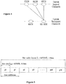
- FIG. 1 illustrates a mapping relationship between a downlink physical channel and a downlink transport channel.
- FIG. 2 illustrates a mapping relationship between an uplink physical channel and an uplink transport channel. The above-described physical channels and transport channels are mapped to each other as illustrated in FIGs. 1 and 2 .
- a logical channel classified as a control channel includes a broadcast control channel (BCCH), a paging control channel (PCCH), a common control channel (CCCH), a multicast control channel (MCCH), and a dedicated control channel (DCCH).
- a logical channel classified as a traffic channel includes a dedicated traffic channel (DTCH) and a multicast traffic channel (MTCH).
- FIG. 3 illustrates a mapping relationship between a downlink transport channel and a downlink logical channel.
- FIG. 4 illustrates a mapping relationship between an uplink transport channel and an uplink logical channel.
- an uplink/downlink data packet is transmitted in units of subframes.
- One subframe is defined as a prescribed time duration including a plurality of OFDM symbols.
- the 3GPP supports radio frame structure type 1 applicable to frequency division duplex (FDD) and radio frame structure type 2 applicable to time division duplex (TDD).
- FDD frequency division duplex
- TDD time division duplex
- FIG. 5 illustrates the radio frame structure type 1.
- the radio frame type 1 consists of 10 subframes.
- One subframe consists of 2 slots.
- FIG. 6 illustrates the radio frame structure type 2.
- the radio frame type 2 is comprised of two half-frames. Each half-frame consists of 5 subframes, a downlink pilot time slot (DwPTS), a guard period (GP), and an uplink pilot time slot (UpPTS).
- DwPTS downlink pilot time slot
- GP guard period
- UpPTS uplink pilot time slot
- One subframe consists of two slots.
- the DwPTS is used for an initial cell search, for synchronization or for channel estimation.
- the UpPTS is used for channel estimation in an evolved Node B (eNB), uplink transmission synchronization of a User Equipment (UE).
- eNB evolved Node B
- UE User Equipment
- the GP is an interval for eliminating interference caused by multi-path delay of downlink signal between uplink and downlink. Namely, irrespective of a radio frame type, one subframe consists of two slots.
- FIG. 7 illustrates a downlink slot structure of LTE.
- a signal transmitted in each slot may be represented by a resource grid comprised of subcarriers and OFDM symbols.
- denotes the number of resource blocks (RBs) in a downlink denotes the number of subcarriers constituting one RB, and denotes the number of OFDM symbols in one downlink slot.
- RBs resource blocks
- FIG. 8 illustrates an uplink slot structure of LTE.
- a signal transmitted in each slot may be represented by a resource grid comprised of subcarriers and OFDM symbols.
- denotes the number of resource blocks (RBs) in an uplink denotes the number of subcarriers constituting one RB, and denotes the number of OFDM symbols in one uplink slot.
- a resource element refers to one subcarrier and one OFDM symbol as a resource unit defined by indexes (a, b) (where a is an index on a frequency domain and b is an index on a time domain) within the uplink slot and the downlink slot.
- the eNB transmits control information to a downlink to control a UL-SCH which is an uplink transport channel.
- the control information transmitted to the downlink informs the UE of the number of RBs transmitted through the UL-SCH and a modulation order.
- the control information informs the UE of a payload size of the data.
- the payload size may be defined as the sum of the size of information (e.g., the size of data, or the size of control information) transmitted from a medium access control (MAC) layer and the size of cyclic redundancy check (CRC) attached arbitrarily to the information in a physical layer.
- MAC medium access control
- CRC cyclic redundancy check
- the payload of the control information may not include the size of the CRC because the CRC cannot be attached to the control information according to the size of the control information before the CRC is attached to the control information. Specifically, if the size of the control information to which the CRC is not attached is smaller than or equal to 11 bits, the CRC is not attached to the control information. In addition, if the size of the control information to which the CRC is not attached is greater than or equal to 12 bits, the CRC is attached to the control information.
- Data and control information may be multiplexed together and transmitted through the UL-SCH.
- CQI Channel Quality Information
- PMI Precoding Matrix Indicator
- RI Rank Indication
- a scheme for encoding the data differs from a scheme for encoding the control information.
- a block error rate (BLER) of the data and a BLER of the control information, demanded by the eNB may differ from each other.
- the conventional system was upgraded such that the code rate of the control information is compensated for by an offset that can be changed by the eNB as compared with the code rate of the data.
- the code rate of the data may be varied by information multiplexed with the data. Moreover, if the data is not transmitted, the UE cannot estimate a code rate of CQI/PMI or rank indication for example. Accordingly, a method for calculating a code rate of transmitted information (e.g., CQI/PMI or rank indication) according to a combination of information transmitted through the UL-SCH is demanded.
- a code rate of transmitted information e.g., CQI/PMI or rank indication
- a success probability of receiving the data packet is increased even though not all resources employed when the data packet is initially transmitted are used.
- the communication system when the communication system operates such that the initial data packet is transmitted without errors with a probability of 90%, the system does not encounter any problem even when the data packet is re-transmitted at a code rate higher than a code rate of the initial data packet. Transmitting a data packet at a high code rate means that less physical transmission resources are used than during the initial transmission of the data packet.
- a code rate of CQI/PMI or rank indication is calculated using the total number of symbols of the data when re-transmitting the data packet, a code rate for stably transmitting the CQI/PMI or rank indication may not be set. Therefore, when data is re-transmitted, a code rate setting method for stably transmitting the CQI/PMI or rank indication is demanded.
- a conventional mobile is commanded by a base station to reduce the amount of total information bits (i.e., data and control bits) that are retransmitted. This does not result in an increased error rate for the data bits because the retransmitted payload data is soft combined with the original payload data.
- corresponding control data of the two signals are not combined for decoding/demodulation. That is, in the conventional system, the truncated control bits of the retransmitted signal are used for code rate setting, resulting in degraded performance.
- the present invention compensates for this degradation in performance by reusing the original control data in a novel fashion.
- EP 0 944 199 A1 discloses a method of generating a data sequence suitable for transmission of variable length frames having payload data of variable length in an environment where a code error may occur.
- a code rate of CQI/PMI or rank indication is calculated using the total number of symbols of the data when re-transmitting the data packet, a code rate for stably transmitting the CQI/PMI or rank indication may not be set. Therefore, when data is re-transmitted, a code rate setting method for stably transmitting the CQI/PMI or rank indication is demanded.
- a conventional mobile is commanded by a base station to reduce the amount of total information bits (i.e., data and control bits) that are retransmitted. This does not result in an increased error rate for the data bits because the retransmitted payload data is soft combined with the original payload data.
- corresponding control data of the two signals are not combined for decoding/demodulation. That is, in the conventional system, the truncated control bits of the retransmitted signal are used for code rate setting, resulting in degraded performance.
- the present invention compensates for this degradation in performance by reusing the original control data in a novel fashion.
- the present invention is directed to a method and apparatus for transmitting control information through a physical uplink shared channel (PUSCH) without data.
- the method is according to claim 1 and the apparatus according to claim 7. Particular embodiments are further defined in claims 2-3 and 8.
- the present invention is also directed to a method and apparatus for processing control information received through a physical uplink shared channel (PUSCH) without data as set out in claims 4 and 9, with particular embodiments further defined in claims 5, 6, 10 and 11.
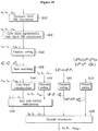
- FIG. 9 illustrates processing of data and control information transmitted through a UL-SCH which is an uplink transport channel.
- a transport block (TB) CRC is attached to the TB of data transmitted to an uplink in step S901.
- the data is to be multiplexed with control information (CQI/PMI or rank indication).
- the CRC attached data is segmented into multiple code blocks (CBs) according to the size of the TB in step S902 and a CB CRC is attached to the CBs in step S903.
- Channel coding is performed upon the CRC-attached CBs in step S904.
- the channel coded data is rate-matched in step S905 and CBs are concatenated in step S906.
- the concatenated CBs are multiplexed with control information in step S907.
- a CRC is attached to CQI/PMI in step S908 and channel coding is performed upon the CRC-attached CQI/PMI in step S909.
- the channel-coded CQI/PMI is rate-matched in step S910 and multiplexed with the data in step S907.
- the channel coding process and the rate matching process are described as separate processes, the channel coding process may include the rate matching process in some cases.
- Rank indication is channel-coded in step S911 separately from the data.
- the channel-coded rank indication is rate-matched in step S912.
- the channel coding process and the rate matching process are described as separate processes, the channel coding process may include the rate matching process in some cases.
- a channel interleaving process is performed upon the multiplexed data, CQI/PMI, and rank indication in step S913.
- Channel coding is performed upon acknowledgement (ACK)/negative acknowledgement (NACK) information in step S914 separately from the data, CQI/PMI, and rank indication.
- the ACK/NACK information is inserted through puncturing a part of the channel-interleaved signal.
- the interleaved signal into which the ACK/NACK information is inserted is transmitted to the uplink after physical resource mapping in step S915.
- the channel coded data, CQI/PMI, and rank indication of specific sizes are converted into data, CQI/PMI, and rank indication having prescribed numbers of symbols or bits transmitted in a physical layer through rate matching.
- the number of symbols or bits transmitted in the physical layer should be present with respect to each of the data, CQI/PMI, and rank indication.
- FIG. 10 illustrates an alternative processing of data and control information transmitted through a UL-SCH which is an uplink transport channel.
- the entire transport block is used to calculate the CRC parity bits.
- the bits in a transport block delivered to layer 1 are denoted by a 0 , a 1 , a 2 , a 3 ,..., a A -1 .
- the parity bits are denoted by p 0 ,p 1 ,p 2 ,p 3 ,..., p L -1 .
- A is the size of the transport block and L is the number of parity bits.
- Code block segmentation and code block CRC attachment are performed after transport block CRC attachment in step 110.
- the bits input to the code block segmentation are denoted by b 0 ,b 1 ,b 2 , b 3 ,..., b B -1 where B is the number of bits in the transport block (including CRC).
- the bits after code block segmentation are denoted by c r 0 ,c r 1 ,c r 2 , c r 3 ,..., c r ( Kr -1) , where r is the code block number and K r is the number of bits for code block number r .
- Channel coding is performed after code block segmentation and code block CRC in step 120.
- Rate matching is performed on Turbo coded blocks after channel coding in step 130.
- the bits are denoted by e r 0 ,e r 1 ,e r 2 , e r 3 ,..., e r ( Er -1) , where r is the coded block number, and where E r is the number of rate matched bits for code block number r .
- Code block concatenation is performed after rate matching in step 140.
- the bits after code block concatenation are denoted by f 0 , f 1 , f 2 , f 3 ,..., f G -1 , where G is the total number of coded bits for transmission excluding the bits used for control transmission, when control information is multiplexed with the UL-SCH transmission.
- the channel coding of the channel quality information is performed with input sequence o 0, o 1, o 2 ,...,o O -1 in step 150.
- the output sequence for the channel coding of channel quality information is denoted by q 0 ,q 1 ,q 2 , q 3 ,...,q Q CQI -1 .
- the channel coding of the RI is preformed with input sequence o 0 RI or o 0 RI o 1 RI in step 160.
- o 0 RI and o 0 RI o 1 RI denotes 1-bit RI and denotes 2-bits RI, respectively.
- the channel coding of the HARQ-ACK is performed with input sequence o 0 ACK , o 0 ACK o 1 ACK or o 0 ACK o 1 ACK ⁇ o o ACK ⁇ 1 ACK in step 170.
- Each positive acknowledgement (ACK) is encoded as a binary '1' and each negative acknowledgement (NAK) is encoded as a binary '0'.
- HARQ-ACK can consist of 1-bit of information, i.e., o 0 ACK or 2-bits of information, i.e., o 0 ACK o 1 ACK with o 0 ACK corresponding to ACK/NACK bit for codeword 0 and o 1 ACK corresponding to that for codeword 1.
- HARQ-ACK can consist of more than two bits information, i.e. o 0 ACK o 1 ACK ⁇ o o ACK ⁇ 1 ACK with O ACK >2.
- the bit sequence q 0 ACK , q 1 ACK , q 2 ACK , ... , q Q ACK ⁇ 1 ACK is obtained by concatenation of multiple encoded HARQ-ACK blocks where Q ACK is the total number of coded bits for all the encoded HARQ-ACK blocks.
- the inputs to the data and control multiplexing are the coded bits of the control information denoted by q 0, q 1, q 2, q 3, ..., q Q CQI -1 and the coded bits of the UL-SCH denoted by ⁇ 0 , ⁇ 1 ,f 2 , ⁇ 3 ,..., ⁇ G -1 in step 180.
- H is the total number of coded bits allocated for UL-SCH data and CQI/PMI information.
- the channel interleaving is performed with the output of the data and control multiplexing operation denoted by g 0 , g 1, g 2, g 3, ..., g H' -1 , the encoded rank indication denoted by the q 0 , q 1, q 2, q 3, ..., q QCQI -1 and the encoded HARQ-ACK denoted by q 0 ACK , q 1 ACK , q 2 ACK , ... , q Q ACK ⁇ 1 ACK .
- the bits after channel interleaving are denoted by h 0 , h 1, h 2, ..., h H+Q RI -1 .
- FIG. 11 illustrates a subframe structure after data and control information are multiplexed.
- the subframe after data, CQI/PMI, rank indication, and ACK/NACK information are appropriately multiplexed in a physical layer is as shown in FIG. 11 .
- the number of transmitted symbols means the number of symbols output through rate matching. Therefore, in the present invention, "the number of transmitted symbols” is referred to as the number of symbols output through rate matching.
- a payload size may be defined as the sum of the size of information (e.g., the size of data, or the size of control information) transmitted from a medium access control (MAC) layer and the size of cyclic redundancy check (CRC) attached arbitrarily to the information in a physical layer.
- the payload of the control information may not include the size of the CRC because the CRC may not be attached to the control information according to the size of the control information before the CRC is attached to the control information. Specifically, if the size of the control information to which the CRC is not attached is smaller than or equal to 11 bits, the CRC is not attached to the control information. In addition, if the size of the control information to which the CRC is not attached is greater than or equal to 12 bits, the CRC is attached to the control information.
- a reference modulation and coding scheme may be defined using the code rate and modulation order of the data.
- An MCS of the control information transmitted together with the data may be estimated using the reference MCS and using offset information of the control information.
- MCS data 1 CodeRate ⁇ Modulation Order
- a reference MCS is MCS ref
- a payload size of CQI/PMI is N CQI
- a parameter expressing, in dB, an offset value for compensating for a difference between a block error rate of data and a block error rate of CQI/PMI and a difference between a data encoding scheme and a CQI/PMI encoding scheme is ⁇ CQI
- the number M CQI of transmitted symbols of CQI/PMI may be calculated using the following Equation 2.
- ⁇ ⁇ denotes a ceiling function.
- the ceiling function represents a function whose value is the smallest integer not less than a value within the symbol. For example, ⁇ 2.3 ⁇ indicates 3 because the smallest integer not less than 2.3 is 3.
- a payload size of rank indication is N RI
- a parameter expressing, in dB, an offset value for compensating for a difference between a block error rate of data and a block error rate of rank indication and a difference between a data encoding scheme and a rank indication encoding scheme is ⁇ RI
- the number M RI of transmitted symbols of rank indication may be expressed by the following Equation 3.
- the number of transmitted symbols of CQI/PMI and the number of transmitted symbols of rank indication may be calculated.
- the eNB commands transmission of data on an UL-SCH, the eNB informs a UE of only the total number of symbols which can be transmitted when the data and other information are multiplexed, a payload size of the data, and the modulation order of the data. Therefore, agreement between the eNB and the UE is required to calculate the reference MCS.
- the method for calculating the reference MCS uses the code rate and modulation order of data under the assumption that only the data is transmitted on the UL-SCH without transmitting the CQI/PMI or rank indication.
- a reference code rate may be calculated using the following Equation 4.
- CR data N data Q data ⁇ M RE PUSCH
- N data denotes a payload size of data
- Q data denotes a modulation order of data which is a reference modulation order
- M RE PUSCH is the total number of symbols which can be transmitted through a physical channel when transmitting data through the UL-SCH.
- the M RE PUSCH is correspond to M sc PUSCH .
- N symb PUSCH-initial where the M sc PUSCH is the scheduled bandwidth for PUSCH transmission in a current sub-frame for the transport block, and N symb PUSCH is the number of SC-FDMA symbols in the current PUSCH transmission sub-frame.
- the reference MCS MCS ref may be calculated using the following Equation 5.
- CR data denotes a reference code rate
- N data denotes a payload size of data
- Q data denotes a modulation order of data which is a reference modulation order
- M RE PUSCH denotes the total number of symbols which can be transmitted through a physical channel when transmitting data through the UL-SCH.
- Equation 4 the payload size N data of data is defined as a value including the CRC but may not include the CRC for simple approximation.
- the reference MCS is calculated using the payload size N data of data.
- the number of finally transmitted symbols of the CQI/PMI may be calculated using the following Equation 6.
- M CQI ⁇ N CQI ⁇ 10 ⁇ CQI 10 ⁇ MC S ref ⁇
- N CQI denotes a payload size of CQI/PMI
- ⁇ CQI denotes a parameter expressing, in dB, an offset value for compensating for a difference between the block error rate of data and the block error rate of CQI/PMI and a difference between a data encoding scheme and a CQI/PMI encoding scheme
- M CQI denotes the number of transmitted symbols of CQI/PMI after rate matching.
- the number M data of transmitted symbols of data may be calculated using the following Equation 7.
- M data M RE PUSCH ⁇ M CQI
- M RE PUSCH denotes the total number of symbols which can be transmitted through a physical channel when transmitting data on a UL-SCH. Since the data and CQI/PMI are multiplexed after they are rate-matched, the number of symbols obtained by subtracting M CQI from M RE PUSCH is the number M data of symbols of data.
- the number M RI of transmitted symbols of the rank indication may be calculated using the following Equation 8, similarly to when the data and CQI/PMI are transmitted.
- M RI ⁇ N RI ⁇ 10 ⁇ RI 10 ⁇ MC S ref ⁇
- N RI denotes a payload size of rank indication
- ⁇ RI denotes a parameter expressing, in dB, an offset value for compensating for a difference between the block error rate of data and the block error rate of rank indication and a difference between a data encoding scheme and a rank indication encoding scheme
- M RI denotes the number of transmitted symbols of rank indication.
- M data M RE PUSCH ⁇ M RI
- M RE PUSCH denotes the total number of symbols which can be transmitted through a physical channel when transmitting data on a UL-SCH. Since the data and rank indication are multiplexed after they are rate-matched, the number of symbols obtained by subtracting M RI from M RE PUSCH is the number M data of symbols of the data.
- M CQI ⁇ N CQI ⁇ 10 ⁇ CQI 10 ⁇ MC S ref ⁇
- M RI ⁇ N RI ⁇ 10 ⁇ RI 10 ⁇ MC S ref ⁇
- M data is calculated using M RE PUSCH as follows.
- M data M RE PUSCH ⁇ M CQI ⁇ M RI
- a calculation result in the UE and the eNB may vary according to calculation methods of multiplication, division, and 10 ⁇ CQI 10 and 10 ⁇ RI 10 in the UE and eNB.
- a method is proposed for calculating the numbers of transmitted symbols of CQI/PMI and rank indication such that a calculation result of division does not generate a remainder.
- the numbers of transmitted symbols of the CQI/PMI and rank indication are calculated using the following Equation 13.
- M X ⁇ N X ⁇ 10 ⁇ X 10 ⁇ MC S ref ⁇
- N X denotes a payload size of information X
- ⁇ X denotes a parameter expressing, in dB, an offset value for compensating for a difference between the block error rate of data and the block error rate of the information X and a difference between a data decoding scheme and an information X decoding scheme
- M X denotes the number of transmitted symbols of information X.
- 10 ⁇ X 10 , and MCS ref defined in Equation 5 may be differently calculated in the UE and the eNB.
- the UE and eNB may promise to previously define 10 ⁇ X 10 as a quantized value.
- Table 1 listed below shows a result of quantizing 10 ⁇ X 10 .
- the UE and the eNB may define 10 ⁇ X 10 as a quantized value as shown in Table 1.
- a quantized result of ⁇ X is shown such that a fractional part thereof can be expressed by 6 bits.
- Table 2 and 3 listed below show a result of calculating ⁇ X when the information X is CQI/PMI or rank indication.
- MCS ref may have various values
- the UE and eNB should store large quantities of values in order to define MCS ref as a quantized value between the UE and the eNB.
- division which may generate a non-integer calculation result should be eliminated.
- the number M X of transmitted symbols of information X can be as follows.
- M X ⁇ N X ⁇ 10 ⁇ X 10 ⁇ MC
- S ref ⁇ ⁇ N X ⁇ 10 ⁇ X 10 ⁇ M RE PUSCH N data ⁇
- Equation 14 a denominator of MCS ref may be transposed towards M X .
- ⁇ ⁇ Y X ⁇
- an equation for calculating the number of transmitted symbols of information X transmitted through a physical channel to solve a quantization problem may be defined as follows.
- M RE PUSCH denotes the total number of symbols which can be transmitted through a physical channel when transmitting data through a UL-SCH
- N data denotes a payload size of data
- N X denotes the payload size of the information X
- M X denotes the number of transmitted symbols of the information X
- ⁇ X denotes a value of quantizing 10 ⁇ X 10 .
- Equation 15 for calculating the number of transmitted symbols of the information X through a physical channel to solve the quantization problem may be defined as follows. M X ⁇ ⁇ ′ X ⁇ N data ⁇ N X ⁇ M RE PUSCH
- M X is the smallest integer satisfying Equation 16.
- the reference MCS is calculated using a code rate and a modulation order of data under the assumption that only the data is transmitted on a UL-SCH without transmitting CQI/PMI or rank indication. Therefore, the reference MCS may not be an accurate value.
- an accurate code rate may not be applied to information (i.e., data, CQI/PMI and rank indication).
- the reference code rate is a code rate of data
- the code rate of data can be determined only when an occupied ratio of CQI/PMI and rank indication among the entire amount of information should be determined.
- the occupied ratio of CQI/PMI and rank indication among the entire amount can be known only when the code rate of data should be determined.
- Embodiment 1-B of the present invention a method is proposed for simultaneously calculating reference code rates of data, CQI/PMI and rank indication in a closed form using the fact that the total number of transmitted symbols is the sum of the numbers of transmitted symbols of the data, CQI/PMI and rank indication on a UL-SCH.
- a reference MCS is an unknown parameter and the numbers of transmitted symbols of CQI/PMI and rank indication are expressed as a function of the reference MCS, since the total number of transmitted symbols of the data, CQI/PMI and rank indication is known, an accurate reference MCS can be obtained.
- the total number of transmitted symbols may be indicated by the sum of the number of transmitted symbols of the CQI/PMI and the number of transmitted symbols of the data. Accordingly, a reference MCS is calculated using the equation for calculating the number of transmitted symbols of the CQI/PMI and the equation for calculating the number of transmitted symbols of the data. Next, the number of transmitted symbols of the data is calculated using the calculated reference MCS and the number of transmitted symbols of the CQI/PMI are calculated.
- the number of transmitted symbols of the data is calculated using the following Equation 17.
- the number of transmitted symbols of the CQI/PMI is expressed by a function of the number of transmitted symbols of the data and a closed-form equation is obtained as shown in the following Equation 18.
- RE PUSCH ⁇ N CQI ⁇ 10 ⁇ CQI 10 ⁇ M data N data ⁇ + M data
- N data denotes a payload size of data
- M data denotes the number of transmitted symbols of the date
- M RE PUSCH denotes the total number of symbols which can be transmitted through a physical channel
- MCS ref denotes a reference MCS
- N CQI denotes a payload size of CQI/PMI
- ⁇ CQI denotes a parameter expressing, in dB, an offset value for compensating for a difference between a block error rate of data and a block error rate of CQI/PMI and a difference between a data encoding scheme and a CQI/PMI encoding scheme
- M CQI denotes the number of transmitted symbols of CQI/PMI.
- Equation 18 may be replaced with the following Equation 19.
- M RE PUSCH ⁇ M data ⁇ N data ⁇ N CQI ⁇ ⁇ CQI ⁇ M data where ⁇ CQI denotes a value obtained by quantizing 10 ⁇ CQI 10 .
- N data , N CQI , ⁇ CQI , and M RE PUSCH are given, M data is the smallest integer satisfying Equation 19.
- M CQI M RE PUSCH ⁇ M data
- the number of transmitted symbols of the rank indication is calculated similarly to the case where only the data and CQI/PMI are transmitted.
- a reference MCS is calculated using the equation for calculating the number of transmitted symbols of the rank indication and the equation for calculating the number of transmitted symbols of the data.
- the number of transmitted symbols of the data is calculated using the calculated reference MCS and the number of transmitted symbols of the rank indication is calculated.
- the number of transmitted symbols of the data is calculated using the following Equation 21.
- the number of transmitted symbols of the rank indication is expressed by a function of the number of transmitted symbols of the data and a closed-form equation is obtained as shown in the following Equation 22.
- M RE PUSCH ⁇ N RI ⁇ 10 ⁇ RI 10 ⁇ M data N data ⁇ + M data
- N data denotes a payload size of data
- M data denotes the number of transmitted symbols of the date
- M RE PUSCH denotes the total number of symbols which can be transmitted through a physical channel
- MCS ref denotes a reference MCS
- N RI denotes a payload size of rank indication
- ⁇ RI denotes a parameter expressing, in dB, an offset value for compensating for a difference between a block error rate of data and a block error rate of rank indication and a difference between a data encoding scheme and a rank indication encoding scheme
- M RI denotes the number of transmitted symbols of rank indication.
- Equation 22 may be replaced with the following Equation 23.
- M RE PUSCH ⁇ M data ⁇ N data ⁇ N RI ⁇ ⁇ RI ⁇ M data where ⁇ RI denotes a value obtained by quantizing 10 ⁇ RI 10 .
- N data , N RI , ⁇ RI , and M RE PUSCH are given, M data is the smallest integer satisfying Equation 23.
- M RI M RE PUSCH ⁇ M data
- the total number of transmitted symbols on a UL-SCH may be indicated by the sum of the number of transmitted symbols of the CQI/PMI, the number of transmitted symbols of the rank indication, and the number of transmitted symbols of the data. Therefore, a reference MCS may be calculated using the equation for calculating the number of transmitted symbols of the CQI/PMI, the equation for calculating the number of transmitted symbols of the rank indication, and the equation for calculating the number of transmitted symbols of the data.
- the number of transmitted symbols of the data may be calculated using the calculated reference MCS and the numbers of transmitted symbols of the CQI/PMI and the rank indication may be calculated.
- the number of transmitted symbols of the data is calculated using the following Equation 25.
- the numbers of transmitted symbols of the CQI/PMI and the rank indication are expressed by a function of the number of transmitted symbols of the data and a closed-form equation is obtained as shown in the following Equation 26.
- N data denotes a payload size of data
- M data denotes the number of transmitted symbols of the date
- M RE PUSCH denotes the total number of symbols which can be transmitted through a physical channel
- MCS ref denotes a reference MCS
- N CQI denotes a payload size of CQI/PMI
- ⁇ CQI denotes a parameter expressing, in dB, an offset value for compensating for a difference between a block error rate of data and a block error rate of CQI/PMI and a difference between a data encoding scheme and a CQI/PMI encoding scheme
- M CQI denotes the number of transmitted symbols of CQI/PMI
- N RI denotes a payload size of rank indication
- ⁇ RI denotes a parameter expressing, in dB, an offset value for compensating for a difference between a block error rate of data and a block error rate of rank indication and a difference between a data
- Equation 26 may be replaced with the following Equation 27.
- M RE PUSCH ⁇ M data ⁇ N data ⁇ N RI ⁇ ⁇ RI ⁇ M data + N CQI ⁇ ⁇ CQI ⁇ M data
- ⁇ CQI denotes a value obtained by quantizing 10 ⁇ CQI 10
- ⁇ RI denotes a value obtained by quantizing 10 ⁇ RI 10
- N data is the smallest integer satisfying Equation 27.
- M RE PUSCH ⁇ M data M CQI + ⁇ N RI ⁇ 10 ⁇ RI 10 ⁇ M CQI N CQI ⁇
- Equation 28 may be replaced with Equation 29.
- M CQI is the smallest integer satisfying Equation 29.
- M RI M RE PUSCH ⁇ M data ⁇ M CQI
- M RE PUSCH ⁇ M data M RI + ⁇ N CQI ⁇ 10 ⁇ CQI 10 ⁇ M RI N RI ⁇
- Equation 31 may be replaced with Equation 32.
- M RI integer satisfying Equation 32.
- M CQI M RE PUSCH ⁇ M data ⁇ M RI
- M CQI or M RI is calculated after calculating M data by the above methods is that values of M data N data , M CQI N CQI , and M RI N RI used as a reference MCS are determined to be almost equal.
- Equation 28 may be expressed by the following Equation 34.
- M RE PUSCH ⁇ M data M CQI + ⁇ N RI ⁇ 10 ⁇ RI 10 ⁇ M data N data ⁇
- Equation 34 may be replaced with Equation 35.
- M CQI is the smallest integer satisfying Equation 35.
- M RI M RE PUSCH ⁇ M data ⁇ M CQI
- Equation 31 may be expressed by the following Equation 37.
- M data , M CQI , and M RI are calculated using Equation 37.
- M RE PUSCH ⁇ M data M RI + ⁇ N CQI ⁇ 10 ⁇ CQI 10 ⁇ M data N data ⁇
- Equation 37 may be replaced with the following Equation 38.
- M RI is the smallest integer satisfying Equation 38.
- M CQI M RE PUSCH ⁇ M data ⁇ M RI
- an order for calculating M data , M RI , and M CQI are as follows.
- Embodiment 1-A the reference MCS does not actually consider an accurate code rate and modulation order of information when data, CQI/PMI, and rank indication are transmitted.
- Embodiment 1-B the method for calculating each information field is complicated.
- Embodiment 1-C a method for expressing the reference MCS as a function of a variety of information is proposed using the fact that an MCS of information most approximates to the reference MCS when utilizing Embodiment 1-B. That is, an approximated equation is used as follows. MC S ref ⁇ M data N data ⁇ M CQI N CQI ⁇ M RI N RI where reference symbol " ⁇ " indicates that a left value and a right vale are approximately equal.
- the reference MCS may be obtained using the following Equation 41 without calculating the number of transmitted symbols of information.
- an approximate reference MCS may be calculated using the fact that the sum of the numbers of transmitted symbols of corresponding information is equal to the total number of symbols transmitted on an UL-SCH.
- the reference MCS since the number of transmitted symbols of corresponding information is determined by an offset value for compensating for a difference in a coding gain or an operation block error rate with respect to data, the reference MCS may be defined as follows.
- the reference MCS is defined as a value obtained by dividing the total number of symbols transmitted on a UL-SCH by the sum of payload sizes of transmitted information.
- offset values for compensating for a difference with the reference MCS of data such as a difference in an encoding scheme, in an operation block error rate, etc. are multiplied to the payload size of corresponding information.
- the numbers of actually transmitted symbols of CQI/PMI and rank indication may be calculated using the following Equation 46.
- N X denotes a payload size of information X
- ⁇ X denotes a parameter expressing, in dB, an offset value for compensating for a difference between a data decoding scheme and an information (X) decoding scheme
- M X denotes the number of transmitted symbols of information X.
- the information X may be CQI/PMI or rank indication.
- the number of transmitted symbols of data is a value obtained by subtracting the numbers of transmitted symbols of CQI/PMI and rank indication from the total number of symbols which can be transmitted.
- CQI/PMI and rank indication may be transmitted on the UL-SCH without transmitting the data.
- an eNB informs a UE of only the total number of symbols transmitted on the UL-SCH. Therefore, a reference MCS is not present.
- a method is proposed for calculating the reference MCS when CQI/PMI and rank indication are transmitted on the UL-SCH.
- Embodiment 2-A a method is proposed for calculating a reference MCS using the code rate and modulation order of CQI/PMI under the assumption that only the CQI/PMI is transmitted on a UL-SCH when the CQI/PMI and rank indication are transmitted.
- the code rate of the CQI/PMI may be defined as follows.
- CR CQI N CQI Q CQI ⁇ M RE PUSCH
- CR CQI denotes a reference code rate
- N CQI denotes a payload size of CQI/PMI
- Q CQI denotes a modulation order of CQI/PMI which is a reference modulation order
- M RE PUSCH denotes the number of symbols which can be transmitted through a physical channel when transmitting CQI/PMI on a UL-SCH.
- the reference MCS may be calculated as follows.
- the number of transmitted symbols of the rank indication is calculated first using a reference MCS as shown in the following Equation 52.
- the number of transmitted symbols of the CQI/PMI is calculated by subtracting the number of transmitted symbols of the rank indication from the total number of symbols which can be transmitted through a physical channel.
- N RI denotes a payload size of rank indication
- ⁇ RI denotes a parameter expressing, in dB, an offset value for compensating for a difference between a block error rate of data and a block error rate of rank indication and a difference between a data encoding scheme and a rank indication encoding scheme
- M RI denotes the number of transmitted symbols of rank indication
- M RE PUSCH denotes the total number of symbols which can be transmitted through a physical channel
- M CQI denotes the number of transmitted symbols of CQI/PMI.
- Embodiment 2-A may be differently implemented in a UE and an eNB as described in Embodiments 1-Aand 1-B.
- Equation 52 may be replaced with the following Equation 54.
- Equation 54 M RI ⁇ N CQI ⁇ N RI ⁇ ⁇ RI ⁇ M RE PUSCH
- M RI is the smallest integer satisfying Equation 54.
- M CQI is calculated using Equation 53.
- an accurate code rate is not applied to information (i.e., CQI/PMI and rank indication).
- a reference code rate is a code rate of the CQI/PMI
- the code rate of the CQI/PMI can be determined only when an occupied ratio of rank indication among the entire amount of information should be determined.
- the method described in Embodiment 2-A assumes the code rate of the CQI/PMI in an ideal state as the reference code rate under the assumption that only the CQI/PMI is transmitted.
- Embodiment 2-B a method is proposed for simultaneously calculating reference code rates of CQI/PMI and rank indication in a closed form using the fact that the total number of transmitted symbols is the sum of the numbers of transmitted symbols of the CQI/PMI and rank indication on a UL-SCH.
- a reference MCS is an unknown parameter and the numbers of transmitted symbols of CQI/PMI and rank indication are expressed as a function of the reference MCS, since the total number of transmitted symbols of the CQI/PMI and rank indication is known, an accurate reference MCS can be obtained.
- the total number of symbols transmitted on the UL-SCH may be indicated by the sum of the number of transmitted symbols of the CQI/PMI and the number of transmitted symbols of the rank indication. Accordingly, a reference MCS is calculated using the equation for calculating the number of transmitted symbols of the rank indication and the equation for calculating the number of finally transmitted symbols of the CQI/PMI. The number of transmitted symbols of the rank indication is calculated using the calculated reference MCS and then the number of transmitted symbols of the CQI/PMI is calculated.
- the number of transmitted symbols of the rank indication is calculated using the following Equation 55.
- the number of transmitted symbols of the CQI/PMI is expressed as a function of the number of transmitted symbols of the rank indication and a closed-form equation is obtained as shown in the following Equation 56.
- M RE PUSCH M CQI + M RI
- M RE PUSCH M CQI + ⁇ N RI ⁇ 10 ⁇ RI 10 ⁇ MC
- S ref ⁇ M CQI + ⁇ N RI ⁇ 10 ⁇ RI 10 ⁇ M CQI N CQI ⁇
- N RI denotes a payload size of rank indication
- ⁇ RI denotes a parameter expressing, in dB, an offset value for compensating for a difference between a block error rate of data and a block error rate of rank indication and a difference between a data encoding scheme and a rank indication encoding scheme
- M RI denotes the number of transmitted symbols of rank indication
- M RE PUSCH denotes the total number of symbols which can be transmitted through a physical channel
- M CQI denotes the number of transmitted symbols of CQI/PMI.
- Equation 56 may be replaced with the following Equation 57.
- N RI , N CQI , ⁇ RI , and M RE PUSCH are given, M CQI is the smallest integer satisfying Equation 57.
- Embodiment 2-C uses the same principle as Embodiment 1-C. Since there is no transmitted data, rank indication is calculated first when calculating CQI/PMI. Accordingly, when the rank indication and CQI/PMI are transmitted on a UL-SCH, a reference MCS is defined as follows.
- the number of transmitted symbols of the rank indication is calculated using the following Equation 59.
- the number of transmitted symbols of the CQI/PMI is a calculated by subtracting the number of transmitted symbols of the rank indication from the total number of symbols transmitted on the UL-SCH.
- N X denotes a payload size of information X
- ⁇ X denotes a parameter expressing, in dB, an offset value for compensating for a difference between a data decoding scheme and an information (X) decoding scheme
- M X denotes the number of transmitted symbols of information X.
- the information X may correspond to the rank indication.
- ACK/NACK information is inserted through puncturing multiplexed data, CQI/PMI, and rank indication and thus a code rate of the information can be changed.
- an eNB does not always know whether or not a UE transmits ACK/NACK information, the number of transmitted symbols of ACK/NACK information is independently calculated using a reference MCS after the number of occupied symbols on a UL-SCH.
- N A / N denotes a payload size of ACK/NACK information
- ⁇ A / N denotes a parameter expressing, in dB, an offset value for compensating for a difference between a block error rate of data and a block error rate of ACK/NACK information and a difference between a data encoding scheme and a ACK/NACK information encoding scheme
- M A / N denotes the number of finally transmitted symbols of ACK/NACK information.
- a method for calculating the number of transmitted symbols of ACK/NACK information through a physical channel is as follows.
- ⁇ A / N denotes a value obtained by quantizing 10 ⁇ A / N 10 .
- M A / N is the smallest integer satisfying Equation 61.
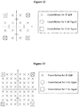
- ACK/NACK information and rank indication transmitted on a UL-SCH always use quadrature phase shift keying (QPSK) or binary phase shift keying (BPSK) modulation.
- QPSK quadrature phase shift keying
- BPSK binary phase shift keying
- the ACK/NACK and rank indication may use only 4 outermost coordinates (2 outermost coordinates when BPSK is used) of a modulation constellation of the data or CQI/PMI.
- FIG. 12 illustrates an example of modulation constellation coordinates used by ACK/NACK information and rank indication when data and CQI/PMI use a 16 quadrature amplitude modulation (QAM) scheme.
- FIG. 13 illustrates an example of modulation constellation coordinates used by ACK/NACK information and rank indication when data and CQI/PMI use a 64 QAM scheme.
- M A / N and M RI are calculated using the above-described Embodiments 1-A, 1-B, 2-A, and 2-B.
- the modulation order of the data or CQI/PMI is 16 QAM
- the maximum numbers of transmissible symbols of rank indication and ACK/NACK information may be limited.
- M A / N which is the numbers of transmitted symbols of the ACK/NACK information
- M A / N is set to the maximum numbers of transmissible symbols of the ACK/NACK information.
- M RI which is the numbers of transmitted symbols of the ACK/NACK information
- M RI is set to the maximum numbers of transmissible symbols of the rank indication.
- the maximum numbers or values of M A / N and M RI may be 12 ⁇ N RB ⁇ 4.
- N RB denotes the number of resource blocks (RBs) transmitted through a physical uplink shared channel (PUSCH). If one RB is transmitted through the PUSCH, the maximum values of M A / N and M RI are 48.
- the number of transmitted symbols of the rank indication may be calculated last according to circumstances. Then it is confirmed whether the number M RI of transmitted symbols of the rank indication exceeds a maximum transmissible value. If M RI exceeds the maximum value, M RI is limited to the maximum value and symbols of the data or CQI/PMI corresponding to a difference between the calculated M RI and the maximum transmissible value are further transmitted.
- a reference code rate greater than 1 may be set or calculated. If the reference code rate is greater than 1, CQI/PMI, rank indication, and ACK/NACK information are not decoded in an eNB and a UE may transmit unnecessary information. In this case, the number of transmitted symbols of the CQI/PMI, rank indication, and ACK/NACK information may be set to 0 and only data may be transmitted.
- an eNB may not generate a circumstance having a code rate greater than 1. If a UE senses such a circumstance, it is determined that the eNB has made a mistake or the UE has read different control information so that no information may be transmitted to the uplink.
- Retransmission may be commended by eNB or may be performed via a predetermined schedule.
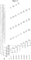
- FIG. 14 shows a HARQ process for explaining data retransmission. As shown in FIG. 14 , it is configured that maximum process is set to be 8 processes and maximum retransmission time is set to be 4. In each process, when the UE receives UL_Grant from the eNB at n th subframe timing, the UE start to transmit data in n+4 th subframe.
- Process 1 if the UE does not receive ACK from the eNB during 3 times retransmission of data (e.g., denoted by '1' in FIG. 14 ) stored in a buffer after starting to transmit data in a n+4 th subframe, the UE performs buffer flush, reconstructs the data and transmits the reconstructed data (e.g., denoted by 1 re in FIG. 14 ).
- Process 2 is an identical case to the process 1.
- Process 3 if the UE receives ACK from the eNB after retransmitting data (e.g., dented by 3 in FIG. 14 ) 2 times, the UE transmits new data (e.g., denoted by 3' in FIG.
- Process 3 if the UE does not receive ACK from the eNB after transmitting the new data, the UE retransmits the new data at 5 th transmission timing.
- Processes 4 to 6 can be explained as described above. In addition, each of processes 1 to 8 is operated independently.
- the communication system when the communication system operates such that the initial data packet is transmitted without errors with a probability of 90%, the system does not encounter any problem even when the data packet is re-transmitted at a code rate higher than a code rate of the initial data packet. Transmitting a data packet at a high code rate means that less physical transmission resources are used than during the initial transmission of the data packet.
- a method for calculating a reference MCS using a packet size of data and the total number of symbols which can be transmitted through a PUSCH and a method for calculating the number of transmitted symbols of CQI/PMI and rank indication using the reference MCS have been proposed.
- CQI/PMI and/or rank indication may be multiplexed with re-transmitted data and then may be transmitted.
- FIG. 15 is a diagram explaining a use relationship of a reference MCS during re-transmission of data. As illustrated in FIG. 15 , while data is re-transmitted through a PUSCH, a method for calculating the numbers of transmitted symbols of CQI/PMI, rank indication, and ACK/NACK information is proposed using a code rate used during the initial transmission of data.
- a reference MCS in the following Equation 62 to calculate the number of transmitted symbols of information X employs a reference MCS used when data is initially transmitted.
- MCS ref denotes a reference MCS when the data is initially transmitted
- N X denotes a payload size of information X
- ⁇ X denotes a parameter expressing, in dB, an offset value for compensating for a difference between the decoding scheme of data and the decoding scheme of the information X
- M X denotes the number of transmitted symbols of information X.
- the information X can be CQI/PMI, rank indication or ACK/NACK information.
- the equation 62 can be expressed by the following equation 63.
- Q' is the number of transmitted symbols of the control information (e.g., CQI/PMI, rank indication or ACK/NACK information) when the data is retransmitted
- O is the payload size of the control information when the data is retransmitted.
- N symb PUSCH-initial is a number of SC-FDMA symbols per subframe for Physical Uplink Shared Channel (PUSCH) transmission when the data is initially transmitted and M sc P ⁇ U ⁇ S ⁇ C ⁇ H ⁇ - ⁇ initial is a scheduled bandwidth PUSCH transmission when the data is initially transmitted.
- M sc P ⁇ U ⁇ S ⁇ C ⁇ H ⁇ - ⁇ initial is the total number of transmissible symbols of Physical Uplink Shared Channel (PUSCH) when the data is initially transmitted.
- PUSCH Physical Uplink Shared Channel
- ⁇ offset PUSCH is the offset value.
- ⁇ r 0 C ⁇ 1
- K r is the payload size of the data when the data is initially transmitted
- r is code block number of the data before channel coding
- K r is a number of bits in code block number r
- C is a total number of code blocks.
- RV redundancy version
- a function of each module of a UE during re-transmission of the data is as follows.
- FIG. 16 is a block diagram of a UE according to an exemplary embodiment of the present invention.
- a UE 130 includes a first channel coding module 131, a second channel coding module 132, and a transport module 133.
- the UE 130 may further include modules such as a multiplexing module, a transport module, and an interleaving module but these are omitted for convenience of description.
- the first channel coding module 131 performs channel coding upon data to be re-transmitted.
- the second channel coding module 132 performs channel coding upon control information.
- the second channel coding module 132 calculates the number of transmitted symbols of the control channel by using the Equation 63.
- the transport module 133 performs channel interleaving upon the first channel-coded data and the second channel-coded control information and transmits the interleaved uplink signal to an uplink.
- a code rate for stably transmitting the CQI/PMI and/or rank indication during re-transmission of data can be set.
- an uplink signal including the data and control information can be transmitted by accurately calculating code rates of the data and control information.
- the present invention may be applied to a UE, an eNB or other equipment of a radio mobile communication system. If applied to an eNB, the eNB performs a deinterleaving and decoding operation to derive the signal from the encoded/interleaved signal sent by the UE.
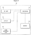
- FIG. 17 is a block diagram showing constitutional elements of a device 50, that can be either a UE or an eNB, and that can perform the methods described above.
- Device 50 includes a processor 51, a memory 52, a radio frequency (RF) unit 53, a display unit 54, and a user interface unit 55. Layers of the radio interface protocol are implemented in the processor 51.
- the processor 51 provides the control plane and the user plane. The function of each layer can be implemented in the processor 51.
- the processor 51 may also include a contention resolution timer.
- the memory 52 is coupled to the processor 51 and stores an operating system, applications, and general files.
- the display unit 54 displays a variety of information and may use a well-known element such as a liquid crystal display (LCD), an organic light emitting diode (OLED), etc.
- the user interface unit 55 can be configured with a combination of well-known user interfaces such as a keypad, a touch screen, etc.
- the RF unit 53 is coupled to the processor 51 and transmits and/or receives radio signals.
- the eNB refers to a terminal node of a network communicating directly with the UE.
- a specific operation described as being performed by the eNB may be performed by an upper node of the eNB.
- the eNB or any other network nodes may perform various operations for communication with the UE in a network comprised of a plurality of network nodes including the eNB.
- the term 'eNB' may be replaced with the term 'fixed station', 'Node B', 'access point', etc.
- the term 'UE' corresponds to a mobile station (MS) and the MS may be replaced with the term 'subscriber station' (SS), 'mobile subscriber station' (MSS), 'mobile terminal', etc.
- the UE employed in the present invention may be a personal digital assistant (PDA), a cellular phone, a personal communication service (PCS) phone, a global system for mobile (GSM) phone, a wideband code division multiple access (wide CDMA) phone, a mobile broadband system (MBS) phone, etc.
- PDA personal digital assistant
- PCS personal communication service
- GSM global system for mobile
- WCS mobile broadband system
- the embodiments of the present invention may be implemented by various means, for example, hardware, firmware, software, or a combination thereof.
- ASICs application specific integrated circuits
- DSPs digital signal processors
- DSPDs digital signal processing devices
- PLDs programmable logic devices
- FPGAs field programmable gate arrays
- methods according to the embodiments of the present invention may be implemented in the form of modules, procedures, functions, etc. which perform the above-described functions or operations.
- Software code may be stored in a memory unit so as to be driven by a processor.
- the memory unit is located at the interior or exterior of the processor and may transmit data to and receive data from the processor via various known means.
Abstract
Description
- The present invention relates to a method for transmitting an uplink signal including control information and data through an uplink channel.
- The link channel structure and mapping of the 3rd generation partnership project (3GPP) long term evolution (LTE) will now be described. A downlink physical channel includes a physical downlink shared channel (PDSCH), a physical broadcast channel (PBCH), a physical multicast channel (PMCH), a physical control format indicator channel (PCFICH), a physical downlink control channel (PDCCH), and a physical hybrid ARQ indicator channel (PHICH). An uplink physical channel includes a physical uplink shared channel (PUSCH), a physical uplink control channel (PUCCH), and a physical random access channel (PRACH).
- A downlink transport channel includes a broadcast channel (BCH), a downlink shared channel (DL-SCH), a paging channel (PCH), and a multicast channel (MCH). An uplink transport channel includes an uplink shared channel (UL-SCH) and a random access channel (RACH).
-
FIG. 1 illustrates a mapping relationship between a downlink physical channel and a downlink transport channel.FIG. 2 illustrates a mapping relationship between an uplink physical channel and an uplink transport channel. The above-described physical channels and transport channels are mapped to each other as illustrated inFIGs. 1 and 2 . - Meanwhile, a logical channel classified as a control channel includes a broadcast control channel (BCCH), a paging control channel (PCCH), a common control channel (CCCH), a multicast control channel (MCCH), and a dedicated control channel (DCCH). A logical channel classified as a traffic channel includes a dedicated traffic channel (DTCH) and a multicast traffic channel (MTCH).
-
FIG. 3 illustrates a mapping relationship between a downlink transport channel and a downlink logical channel.FIG. 4 illustrates a mapping relationship between an uplink transport channel and an uplink logical channel. - In a cellular orthogonal frequency division multiplexing (OFDM) radio packet communication system, an uplink/downlink data packet is transmitted in units of subframes. One subframe is defined as a prescribed time duration including a plurality of OFDM symbols.
- The 3GPP supports radio
frame structure type 1 applicable to frequency division duplex (FDD) and radioframe structure type 2 applicable to time division duplex (TDD). -
FIG. 5 illustrates the radioframe structure type 1. Theradio frame type 1 consists of 10 subframes. One subframe consists of 2 slots. -
FIG. 6 illustrates the radioframe structure type 2. Theradio frame type 2 is comprised of two half-frames. Each half-frame consists of 5 subframes, a downlink pilot time slot (DwPTS), a guard period (GP), and an uplink pilot time slot (UpPTS). One subframe consists of two slots. The DwPTS is used for an initial cell search, for synchronization or for channel estimation. The UpPTS is used for channel estimation in an evolved Node B (eNB), uplink transmission synchronization of a User Equipment (UE). The GP is an interval for eliminating interference caused by multi-path delay of downlink signal between uplink and downlink. Namely, irrespective of a radio frame type, one subframe consists of two slots. -
FIG. 7 illustrates a downlink slot structure of LTE. As illustrated inFIG. 7 , a signal transmitted in each slot may be represented by a resource grid comprised of subcarriers and OFDM symbols. At this time, denotes the number of resource blocks (RBs) in a downlink, denotes the number of subcarriers constituting one RB, and denotes the number of OFDM symbols in one downlink slot. -
FIG. 8 illustrates an uplink slot structure of LTE. As illustrated inFIG. 8 , a signal transmitted in each slot may be represented by a resource grid comprised of subcarriers and OFDM symbols. At this time, denotes the number of resource blocks (RBs) in an uplink, denotes the number of subcarriers constituting one RB, and denotes the number of OFDM symbols in one uplink slot. A resource element refers to one subcarrier and one OFDM symbol as a resource unit defined by indexes (a, b) (where a is an index on a frequency domain and b is an index on a time domain) within the uplink slot and the downlink slot. - Meanwhile, the eNB transmits control information to a downlink to control a UL-SCH which is an uplink transport channel. The control information transmitted to the downlink informs the UE of the number of RBs transmitted through the UL-SCH and a modulation order. In addition, when data is transmitted to an uplink, the control information informs the UE of a payload size of the data. The payload size may be defined as the sum of the size of information (e.g., the size of data, or the size of control information) transmitted from a medium access control (MAC) layer and the size of cyclic redundancy check (CRC) attached arbitrarily to the information in a physical layer. The payload of the control information may not include the size of the CRC because the CRC cannot be attached to the control information according to the size of the control information before the CRC is attached to the control information. Specifically, if the size of the control information to which the CRC is not attached is smaller than or equal to 11 bits, the CRC is not attached to the control information. In addition, if the size of the control information to which the CRC is not attached is greater than or equal to 12 bits, the CRC is attached to the control information.
- Data and control information (e.g., Channel Quality Information (CQI) /Precoding Matrix Indicator (PMI) or Rank Indication (RI)) may be multiplexed together and transmitted through the UL-SCH. In the conventional system, a scheme for encoding the data differs from a scheme for encoding the control information. Furthermore, in the conventional system, a block error rate (BLER) of the data and a BLER of the control information, demanded by the eNB, may differ from each other.
- Furthermore, in the conventional system, even though a code rate of data is known using the modulation order, the number of RBs, and the payload size of data, a code rate of control information cannot be known. Moreover, since the data and the control information are multiplexed together and then transmitted through the UL-SCH, the number of transmitted symbols of the data cannot be known.
- To solve such problems, the conventional system was upgraded such that the code rate of the control information is compensated for by an offset that can be changed by the eNB as compared with the code rate of the data.
- Even if the system is managed as described above, the code rate of the data may be varied by information multiplexed with the data. Moreover, if the data is not transmitted, the UE cannot estimate a code rate of CQI/PMI or rank indication for example. Accordingly, a method for calculating a code rate of transmitted information (e.g., CQI/PMI or rank indication) according to a combination of information transmitted through the UL-SCH is demanded.
- Also, in the conventional communication system, if an error occurs in a data packet due to failure of receipt after the data packet is transmitted, the corresponding data packet is re-transmitted.
- Also, in the case where re-transmission occurs, if decoding is performed using an initially received data packet and a data packet received by re-transmission, a success probability of receiving the data packet is increased even though not all resources employed when the data packet is initially transmitted are used.
- For example, when the communication system operates such that the initial data packet is transmitted without errors with a probability of 90%, the system does not encounter any problem even when the data packet is re-transmitted at a code rate higher than a code rate of the initial data packet. Transmitting a data packet at a high code rate means that less physical transmission resources are used than during the initial transmission of the data packet.
- If a code rate of CQI/PMI or rank indication is calculated using the total number of symbols of the data when re-transmitting the data packet, a code rate for stably transmitting the CQI/PMI or rank indication may not be set. Therefore, when data is re-transmitted, a code rate setting method for stably transmitting the CQI/PMI or rank indication is demanded.
- In summary, in an attempt to save bandwidth while retransmitting, a conventional mobile is commanded by a base station to reduce the amount of total information bits (i.e., data and control bits) that are retransmitted. This does not result in an increased error rate for the data bits because the retransmitted payload data is soft combined with the original payload data. However, corresponding control data of the two signals are not combined for decoding/demodulation. That is, in the conventional system, the truncated control bits of the retransmitted signal are used for code rate setting, resulting in degraded performance. Thus, the present invention compensates for this degradation in performance by reusing the original control data in a novel fashion.
-
EP 0 944 199 A1 discloses a method of generating a data sequence suitable for transmission of variable length frames having payload data of variable length in an environment where a code error may occur. - If a code rate of CQI/PMI or rank indication is calculated using the total number of symbols of the data when re-transmitting the data packet, a code rate for stably transmitting the CQI/PMI or rank indication may not be set. Therefore, when data is re-transmitted, a code rate setting method for stably transmitting the CQI/PMI or rank indication is demanded.
- In summary, in an attempt to save bandwidth while retransmitting, a conventional mobile is commanded by a base station to reduce the amount of total information bits (i.e., data and control bits) that are retransmitted. This does not result in an increased error rate for the data bits because the retransmitted payload data is soft combined with the original payload data. However, corresponding control data of the two signals are not combined for decoding/demodulation. That is, in the conventional system, the truncated control bits of the retransmitted signal are used for code rate setting, resulting in degraded performance. Thus, the present invention compensates for this degradation in performance by reusing the original control data in a novel fashion.
- Accordingly, the present invention is directed to a method and apparatus for transmitting control information through a physical uplink shared channel (PUSCH) without data. The method is according to
claim 1 and the apparatus according toclaim 7. Particular embodiments are further defined in claims 2-3 and 8. The present invention is also directed to a method and apparatus for processing control information received through a physical uplink shared channel (PUSCH) without data as set out inclaims claims - The accompanying drawings, which are included to provide a further understanding of the invention and are incorporated in and constitute a part of this application, illustrate embodiments of the invention and together with the description serve to explain the principle of the invention.
In the drawings: -
FIG. 1 illustrates a mapping relationship between a downlink physical channel and a downlink transport channel.FIG. 2 illustrates a mapping relationship between an uplink physical channel and an uplink transport channel. -
FIG. 3 illustrates a mapping relationship between a downlink transport channel and a downlink logical channel. -
FIG. 4 illustrates a mapping relationship between an uplink transport channel and an uplink logical channel.FIG. 5 is the radioframe structure type 1. -
FIG. 6 is the radioframe structure type 2. -
FIG. 7 is a downlink slot structure of LTE. -
FIG. 8 is an uplink slot structure of LTE. -
FIG. 9 illustrates a processing of data and control information transmitted through a UL-SCH which is an uplink transport channel. -
FIG. 10 illustrates an alternative processing of data and control information transmitted through a UL-SCH which is an uplink transport channel. -
FIG. 11 is a subframe structure after data and control information are multiplexed. -
FIG. 12 illustrates an example of modulation constellation coordinates. -
FIG. 13 illustrates an example of modulation constellation coordinates. -
FIG. 14 describes HARQ (Hybrid Automatic Repeat request) process for explaining data retransmission. -
FIG. 15 is a diagram explaining a use relationship of a reference MCS during re-transmission of data. -
FIG. 16 is a block diagram of a UE according to an exemplary embodiment of the present invention. -
FIG. 17 is a block diagram showing constitutional elements of adevice 50 that can be either a UE or an eNB. - Reference will now be made in detail to the exemplary embodiments of the present invention, examples of which are illustrated in the accompanying drawings. The detailed description, which will be given below with reference to the accompanying drawings, is intended to explain exemplary embodiments of the present invention, rather than to show the only embodiments that can be implemented according to the invention. The following detailed description includes specific details in order to provide a thorough understanding of the present invention. However, it will be apparent to those skilled in the art that the present invention may be practiced without such specific details. For example, the following description will be given centering on specific terms, but the present invention is not limited thereto and any other terms may be used to represent the same meanings.
-
FIG. 9 illustrates processing of data and control information transmitted through a UL-SCH which is an uplink transport channel. - A transport block (TB) CRC is attached to the TB of data transmitted to an uplink in step S901. The data is to be multiplexed with control information (CQI/PMI or rank indication). The CRC attached data is segmented into multiple code blocks (CBs) according to the size of the TB in step S902 and a CB CRC is attached to the CBs in step S903. Channel coding is performed upon the CRC-attached CBs in step S904. The channel coded data is rate-matched in step S905 and CBs are concatenated in step S906. The concatenated CBs are multiplexed with control information in step S907.
- Meanwhile, a CRC is attached to CQI/PMI in step S908 and channel coding is performed upon the CRC-attached CQI/PMI in step S909. The channel-coded CQI/PMI is rate-matched in step S910 and multiplexed with the data in step S907. Although the channel coding process and the rate matching process are described as separate processes, the channel coding process may include the rate matching process in some cases.
- Rank indication is channel-coded in step S911 separately from the data. The channel-coded rank indication is rate-matched in step S912. Although the channel coding process and the rate matching process are described as separate processes, the channel coding process may include the rate matching process in some cases.
- A channel interleaving process is performed upon the multiplexed data, CQI/PMI, and rank indication in step S913.
Channel coding is performed upon acknowledgement (ACK)/negative acknowledgement (NACK) information in step S914 separately from the data, CQI/PMI, and rank indication. - The ACK/NACK information is inserted through puncturing a part of the channel-interleaved signal. The interleaved signal into which the ACK/NACK information is inserted is transmitted to the uplink after physical resource mapping in step S915.
- The channel coded data, CQI/PMI, and rank indication of specific sizes are converted into data, CQI/PMI, and rank indication having prescribed numbers of symbols or bits transmitted in a physical layer through rate matching. In this case, the number of symbols or bits transmitted in the physical layer should be present with respect to each of the data, CQI/PMI, and rank indication.
-
FIG. 10 illustrates an alternative processing of data and control information transmitted through a UL-SCH which is an uplink transport channel. - Error detection is provided on UL-SCH transport blocks through a Cyclic Redundancy Check (CRC) in step S100.
- The entire transport block is used to calculate the CRC parity bits. The bits in a transport block delivered to
layer 1 are denoted by a 0,a 1,a 2,a 3,...,a A-1 . The parity bits are denoted by p 0 ,p 1 ,p 2 ,p 3,...,p L-1 . A is the size of the transport block and L is the number of parity bits. - Code block segmentation and code block CRC attachment are performed after transport block CRC attachment in
step 110. The bits input to the code block segmentation are denoted by b 0 ,b 1 ,b 2 ,b 3,...,b B-1 where B is the number of bits in the transport block (including CRC). The bits after code block segmentation are denoted by c r0 ,c r1 ,c r2 ,c r3,...,c r(Kr-1) , where r is the code block number and K r is the number of bits for code block number r. - Channel coding is performed after code block segmentation and code block CRC in
step 120. After encoding the bits are denoted by
- Rate matching is performed on Turbo coded blocks after channel coding in
step 130. After rate matching, the bits are denoted by e r0 ,e r1 ,e r2 ,e r3,...,e r(Er-1), where r is the coded block number, and where E r is the number of rate matched bits for code block number r. - Code block concatenation is performed after rate matching in
step 140. The bits after code block concatenation are denoted by f 0, f 1, f 2, f 3,..., f G-1, where G is the total number of coded bits for transmission excluding the bits used for control transmission, when control information is multiplexed with the UL-SCH transmission. - The channel coding of the channel quality information is performed with input sequence o 0, o 1, o 2,...,o O-1 in
step 150. The output sequence for the channel coding of channel quality information is denoted by q 0 ,q 1 ,q 2 ,q 3 ,...,q QCQI -1. - The channel coding of the RI is preformed with
input sequence 

step 160.

- The channel coding of the HARQ-ACK is performed with
input sequence 


codeword 0 and
codeword 1. In addition, HARQ-ACK can consist of more than two bits information, i.e.
bit sequence 
- The inputs to the data and control multiplexing are the coded bits of the control information denoted by q 0, q 1, q 2, q 3,...,q QCQI -1 and the coded bits of the UL-SCH denoted by ƒ 0 ,ƒ 1 ,f2,ƒ3,...,ƒ G-1 in step 180. The output of the data and control multiplexing operation is denoted by g 0, g 1, g 2, g 3,..., g H'-1, where H = (G + QCQI ) and H' = H/Qm and where g i with i = 0,..., H'-1 are column vectors of length Qm . H is the total number of coded bits allocated for UL-SCH data and CQI/PMI information.
- The channel interleaving is performed with the output of the data and control multiplexing operation denoted by g 0, g 1, g 2, g 3,...,g H'-1, the encoded rank indication denoted by the q 0,q 1, q 2, q 3,...,q QCQI-1 and the encoded HARQ-ACK denoted by

- The bits after channel interleaving are denoted by h 0,h 1, h 2,...,h H+QRI -1. The number of modulation symbols in the subframe is given

-
FIG. 11 illustrates a subframe structure after data and control information are multiplexed. The subframe after data, CQI/PMI, rank indication, and ACK/NACK information are appropriately multiplexed in a physical layer is as shown inFIG. 11 . - Hereinafter, a method will be described for calculating code rates of data and control information when data is transmitted through an UL-SCH.
- When data is simultaneously transmitted together with other information (e.g., at least one of CQI/PMI information and rank indication), since such control information transmitted together with the data is multiplexed together with the data after rate matching, the number of transmitted symbols of the data and the number of transmitted symbols of the control information transmitted together with the data are needed upon transmission of the data. Herein, "the number of transmitted symbols" means the number of symbols output through rate matching. Therefore, in the present invention, "the number of transmitted symbols" is referred to as the number of symbols output through rate matching.
- In addition, in the present invention, a payload size may be defined as the sum of the size of information (e.g., the size of data, or the size of control information) transmitted from a medium access control (MAC) layer and the size of cyclic redundancy check (CRC) attached arbitrarily to the information in a physical layer. The payload of the control information may not include the size of the CRC because the CRC may not be attached to the control information according to the size of the control information before the CRC is attached to the control information. Specifically, if the size of the control information to which the CRC is not attached is smaller than or equal to 11 bits, the CRC is not attached to the control information. In addition, if the size of the control information to which the CRC is not attached is greater than or equal to 12 bits, the CRC is attached to the control information.
- If a code rate and a modulation order of the transmitted data are accurately known, a reference modulation and coding scheme (MCS) may be defined using the code rate and modulation order of the data. An MCS of the control information transmitted together with the data may be estimated using the reference MCS and using offset information of the control information.
- Assuming that the inverse of spectral efficiency obtained by a code rate and a modulation order of data is MCSdata, MCSdata may be calculated using the following
Equation 1.
- If a reference MCS is MCSref, a payload size of CQI/PMI is NCQI, and a parameter expressing, in dB, an offset value for compensating for a difference between a block error rate of data and a block error rate of CQI/PMI and a difference between a data encoding scheme and a CQI/PMI encoding scheme is Δ CQI , the number MCQI of transmitted symbols of CQI/PMI may be calculated using the following
Equation 2.
- In
Equation 2, "┌ ┐" denotes a ceiling function. The ceiling function represents a function whose value is the smallest integer not less than a value within the symbol. For example, ┌2.3┐ indicates 3 because the smallest integer not less than 2.3 is 3. - In addition, if reference MCS is MCSref , a payload size of rank indication is NRI, and a parameter expressing, in dB, an offset value for compensating for a difference between a block error rate of data and a block error rate of rank indication and a difference between a data encoding scheme and a rank indication encoding scheme is Δ RI , the number MRI of transmitted symbols of rank indication may be expressed by the following
Equation 3.
- If a code rate and modulation order of data used when calculating a reference MCS are known, the number of transmitted symbols of CQI/PMI and the number of transmitted symbols of rank indication may be calculated. However, if an eNB commands transmission of data on an UL-SCH, the eNB informs a UE of only the total number of symbols which can be transmitted when the data and other information are multiplexed, a payload size of the data, and the modulation order of the data. Therefore, agreement between the eNB and the UE is required to calculate the reference MCS.
- As illustrated in
FIG. 9 , when the data, CQI/PMI, and rank indication are transmitted together, the data, CQI/PMI, and rank indication are rate-matched and then multiplexed. To calculate the number of transmitted symbols of each of the data, CQI/PMI, and rank indication, equations of a complicated closed form or iterative equations should be used. - Accordingly, a method for briefly calculating the reference MCS is proposed. However, if the method for calculating the reference MCS is simplified, an accurate code rate of the information may not be applied.
- The method for calculating the reference MCS uses the code rate and modulation order of data under the assumption that only the data is transmitted on the UL-SCH without transmitting the CQI/PMI or rank indication.
- Specifically, a reference code rate may be calculated using the following
Equation 4.


- Therefore, the reference MCS MCSref may be calculated using the following
Equation 5.

- Generally, a CRC is attached to data to check for errors. In
Equation 4 andEquation 5, the payload size Ndata of data is defined as a value including the CRC but may not include the CRC for simple approximation. - When data and CQI/PMI are transmitted on the UL-SCH, the reference MCS is calculated using the payload size Ndata of data. The number of finally transmitted symbols of the CQI/PMI may be calculated using the following
Equation 6.
- If the number MCQI of transmitted symbols of the CQI/PMI is obtained using
Equation 6, the number Mdata of transmitted symbols of data may be calculated using the followingEquation 7.


- When data and rank indication are transmitted on the UL-SCH, the number MRI of transmitted symbols of the rank indication may be calculated using the following
Equation 8, similarly to when the data and CQI/PMI are transmitted.
- Once MRI is obtained using
Equation 8, the number Mdata of transmitted symbols of data may be calculated using the followingEquation 9.


- When the data, CQI/PMI, and rank indication are transmitted together, the number MCQI of transmitted symbols of CQI/PMI and the number MRI of transmitted symbols of rank indication are calculated using the reference MCS as follows.


- If MCQI and MRI are obtained, Mdata is calculated using


- For accurate decoding of data, CQI/PMI, and rank indication between a UE and an eNB, the above-mentioned calculations should be accurately carried out. However, since the above equations include


- A method is proposed for calculating the numbers of transmitted symbols of CQI/PMI and rank indication such that a calculation result of division does not generate a remainder.
- The numbers of transmitted symbols of the CQI/PMI and rank indication are calculated using the following
Equation 13.
- In
Equation 
Equation 5 may be differently calculated in the UE and the eNB. The UE and eNB may promise to previously define
- Table 1 listed below shows a result of quantizing


[Table 1] Index Δ X 
0(000) 0 dB 1.0000000000 1 (001) 1 dB 1.2500000000 2 (010) 2 dB 1.5781250000 3 (011) 3 dB 1.9843750000 ... ... 2.5000000000 7 (111) 7 dB 3.1562500000 - Table 2 and 3 listed below show a result of calculating βX when the information X is CQI/PMI or rank indication.
[Table 2] Index β RI 0 1.250 1 1.625 2 2.000 3 2.500 4 3.125 5 4.000 6 5.000 7 6.250 8 8.000 9 10.000 10 12.625 11 15.875 12 20.000 13 reserved 14 reserved 15 reserved [Table 3] Index β CQI 0 0.750 1 1.000 2 1.125 3 1.250 4 1.375 5 1.625 6 1.750 7 2.000 8 2.250 9 2.500 10 2.875 11 3.125 12 3.500 13 4.000 14 5.000 15 6.250 - Since MCSref may have various values, the UE and eNB should store large quantities of values in order to define MCSref as a quantized value between the UE and the eNB. However, in order not to store the quantized value, division which may generate a non-integer calculation result should be eliminated.
- Using
Equation 13 andEquation 5, the number MX of transmitted symbols of information X can be as follows.
- In
Equation 14, a denominator of MCSref may be transposed towards MX . When transposing values within a ceiling function, equality ("=") may be converted to inequality ("≥"). Namely, in the ceiling function,
- Thus, an equation for calculating the number of transmitted symbols of information X transmitted through a physical channel to solve a quantization problem may be defined as follows.


integer satisfying Equation 15. - In addition, since βX is greater than 1, the inverse of βX , that is,

Equation 15. The reason why

Equation 15 for calculating the number of transmitted symbols of the information X through a physical channel to solve the quantization problem may be defined as follows.
- When Ndata , NX ,


integer satisfying Equation 16. - In Embodiment 1-A, the reference MCS is calculated using a code rate and a modulation order of data under the assumption that only the data is transmitted on a UL-SCH without transmitting CQI/PMI or rank indication. Therefore, the reference MCS may not be an accurate value.
- Namely, in Embodiment 1-A, an accurate code rate may not be applied to information (i.e., data, CQI/PMI and rank indication). Assuming that the reference code rate is a code rate of data, the code rate of data can be determined only when an occupied ratio of CQI/PMI and rank indication among the entire amount of information should be determined. The occupied ratio of CQI/PMI and rank indication among the entire amount can be known only when the code rate of data should be determined.
- In Embodiment 1-B of the present invention, a method is proposed for simultaneously calculating reference code rates of data, CQI/PMI and rank indication in a closed form using the fact that the total number of transmitted symbols is the sum of the numbers of transmitted symbols of the data, CQI/PMI and rank indication on a UL-SCH. Specifically, assuming that a reference MCS is an unknown parameter and the numbers of transmitted symbols of CQI/PMI and rank indication are expressed as a function of the reference MCS, since the total number of transmitted symbols of the data, CQI/PMI and rank indication is known, an accurate reference MCS can be obtained.
- When only data and CQI/PMI are transmitted, the total number of transmitted symbols may be indicated by the sum of the number of transmitted symbols of the CQI/PMI and the number of transmitted symbols of the data. Accordingly, a reference MCS is calculated using the equation for calculating the number of transmitted symbols of the CQI/PMI and the equation for calculating the number of transmitted symbols of the data. Next, the number of transmitted symbols of the data is calculated using the calculated reference MCS and the number of transmitted symbols of the CQI/PMI are calculated.
- More specifically, the number of transmitted symbols of the data is calculated using the following
Equation 17. In this case, the number of transmitted symbols of the CQI/PMI is expressed by a function of the number of transmitted symbols of the data and a closed-form equation is obtained as shown in the followingEquation 18.

- In
Equation 17 andEquation 18, Ndata denotes a payload size of data, Mdata denotes the number of transmitted symbols of the date,
- Meanwhile, to solve a quantization problem,
Equation 18 may be replaced with the followingEquation 19.


integer satisfying Equation 19. - If Mdata is obtained using
Equation 19, MCQI may be calculated using the followingEquation 20.
- When only data and rank indication are transmitted a UL-SCH, the number of transmitted symbols of the rank indication is calculated similarly to the case where only the data and CQI/PMI are transmitted. A reference MCS is calculated using the equation for calculating the number of transmitted symbols of the rank indication and the equation for calculating the number of transmitted symbols of the data. The number of transmitted symbols of the data is calculated using the calculated reference MCS and the number of transmitted symbols of the rank indication is calculated.
- More specifically, the number of transmitted symbols of the data is calculated using the following
Equation 21. In this case, the number of transmitted symbols of the rank indication is expressed by a function of the number of transmitted symbols of the data and a closed-form equation is obtained as shown in the followingEquation 22.

- In
Equation 21 andEquation 22, Ndata denotes a payload size of data, Mdata denotes the number of transmitted symbols of the date,
- Meanwhile, to solve a quantization problem,
Equation 22 may be replaced with the followingEquation 23.


integer satisfying Equation 23. - If Mdata is obtained using
Equation 23, MRI may be calculated using the followingEquation 24.
- When data, CQI/PMI, and rank indication are transmitted, the total number of transmitted symbols on a UL-SCH may be indicated by the sum of the number of transmitted symbols of the CQI/PMI, the number of transmitted symbols of the rank indication, and the number of transmitted symbols of the data. Therefore, a reference MCS may be calculated using the equation for calculating the number of transmitted symbols of the CQI/PMI, the equation for calculating the number of transmitted symbols of the rank indication, and the equation for calculating the number of transmitted symbols of the data. The number of transmitted symbols of the data may be calculated using the calculated reference MCS and the numbers of transmitted symbols of the CQI/PMI and the rank indication may be calculated.
- More specifically, the number of transmitted symbols of the data is calculated using the following
Equation 25. In this case, the numbers of transmitted symbols of the CQI/PMI and the rank indication are expressed by a function of the number of transmitted symbols of the data and a closed-form equation is obtained as shown in the followingEquation 26.

- In
Equation 25 andEquation 26, Ndata denotes a payload size of data, Mdata denotes the number of transmitted symbols of the date,
- Meanwhile, to solve a quantization problem,
Equation 26 may be replaced with the followingEquation 27.


integer satisfying Equation 27. - If Mdata is obtained, MRI or MCQI is calculated. At this time, a method for calculating MCQI using the following
Equation 28 is proposed after calculating Mdata so that a code rate of rank indication by a ceiling function may be lower than a reference code rate. This is because the rank indication may be more important than CQI/PMI.
- Meanwhile, to solve a quantization problem,
Equation 28 may be replaced withEquation 29.
- When Mdata , N RI, βRI , NCQI , and

integer satisfying Equation 29. - If Mdata and MCQI are obtained, MRI may be calculated as follows.

- Meanwhile, if MRI is calculated before calculating MCQI , the following
Equation 31 may be used.
- To solve a quantization problem,
Equation 31 may be replaced withEquation 32.
- When Mdata , NRI , βRI , NCQI , and

integer satisfying Equation 32. - If Mdata and MRI are obtained, MCQI may be calculated as follows.

- The reason why MCQI or MRI is calculated after calculating Mdata by the above methods is that values of


- In the case where a CRC having a different length is attached to each of data and CQI/PMI or a plurality of CRCs is attached to each of the data and CQI/PMI, the values of


Equation 28 may expressed by the followingEquation 34.
- To solve a quantization problem,
Equation 34 may be replaced withEquation 35.
- When Mdata , Ndata , NRI , βRI , and

integer satisfying Equation 35. - If Mdata and MCQI are obtained, MRI may be calculated as follows.

- Similarly,
Equation 31 may be expressed by the followingEquation 37. Mdata , MCQI , and MRI are calculated usingEquation 37.
- To solve a quantization problem,
Equation 37 may be replaced with the followingEquation 38.
- When Mdata , Ndata , βRI , NCQI , and

integer satisfying Equation 38. - If Mdata and MRI are obtained, MCQI may be calculated as follows.

- In Embodiment 1-B, an order for calculating Mdata, MRI, and MCQI are as follows.
- (1) Step 1 (step for obtaining Mdata ):
Mdata satisfying

- (2) Step 2 (step for obtaining MCQI ):
MCQI satisfying

- (3) Step 3 (step for obtaining MRI ):
MRI is calculated using
- In Embodiment 1-A, the reference MCS does not actually consider an accurate code rate and modulation order of information when data, CQI/PMI, and rank indication are transmitted. In Embodiment 1-B, the method for calculating each information field is complicated. In Embodiment 1-C, a method for expressing the reference MCS as a function of a variety of information is proposed using the fact that an MCS of information most approximates to the reference MCS when utilizing Embodiment 1-B. That is, an approximated equation is used as follows.

- When defining the reference MCS as the ratio of the number of transmitted symbols of information to a payload size of information, a problem of not being aware of the number of transmitted symbols of information arises. However, since the total number of transmitted symbols is known, the reference MCS may be obtained using the following Equation 41 without calculating the number of transmitted symbols of information.

- Using Equation 41, the following Equation 42 may be induced.

- Even though a variety of information is multiplexed and then transmitted, a UE recognizes the total number of transmitted symbols and a payload size of corresponding information. In addition, even when the number of transmitted symbols of corresponding information is unknown, an approximate reference MCS may be calculated using the fact that the sum of the numbers of transmitted symbols of corresponding information is equal to the total number of symbols transmitted on an UL-SCH.
- In this case, since the number of transmitted symbols of corresponding information is determined by an offset value for compensating for a difference in a coding gain or an operation block error rate with respect to data, the reference MCS may be defined as follows.
- (1) When data and CQI/PMI are transmitted on a UL-SCH, the reference MCS may be defined by the following Equation 43.

- (2) When data and rank indication are transmitted on a UL-SCH, the reference MCS may be defined as follows.

- (3) When data, CQI/PMI, and rank indication are transmitted on a UL-SCH, the reference MCS may be defined as follows.

- Namely, the reference MCS is defined as a value obtained by dividing the total number of symbols transmitted on a UL-SCH by the sum of payload sizes of transmitted information. At this time, offset values for compensating for a difference with the reference MCS of data such as a difference in an encoding scheme, in an operation block error rate, etc. are multiplied to the payload size of corresponding information.
- Therefore, the numbers of actually transmitted symbols of CQI/PMI and rank indication may be calculated using the following Equation 46.

- The number of transmitted symbols of data is a value obtained by subtracting the numbers of transmitted symbols of CQI/PMI and rank indication from the total number of symbols which can be transmitted.
- The following examples indicate methods for calculating the number of transmitted symbols of data.
- (1) When data and CQI/PMI are transmitted on a UL-SCH, the number of transmitted symbols of data is calculated as follows.

- (2) When data and rank indication are transmitted on a UL-SCH, the number of transmitted symbols of data is calculated as follows.

- (1) When data, CQI/PMI, and rank indication are transmitted on a UL-SCH, the number of transmitted symbols of data is calculated as follows.

- While the case where data is transmitted on a UL-SCH has been described, CQI/PMI and rank indication may be transmitted on the UL-SCH without transmitting the data.
- Hereinafter, a method will be described for calculating a code rate of control information when data is not transmitted on a UL-SCH.
- In such a case, an eNB informs a UE of only the total number of symbols transmitted on the UL-SCH. Therefore, a reference MCS is not present. A method is proposed for calculating the reference MCS when CQI/PMI and rank indication are transmitted on the UL-SCH.
- In Embodiment 2-A, a method is proposed for calculating a reference MCS using the code rate and modulation order of CQI/PMI under the assumption that only the CQI/PMI is transmitted on a UL-SCH when the CQI/PMI and rank indication are transmitted.
- The code rate of the CQI/PMI may be defined as follows.


- Accordingly, the reference MCS may be calculated as follows.

- When CQI/PMI and rank indication are transmitted together, the number of transmitted symbols of the rank indication is calculated first using a reference MCS as shown in the following
Equation 52. Next, the number of transmitted symbols of the CQI/PMI is calculated by subtracting the number of transmitted symbols of the rank indication from the total number of symbols which can be transmitted through a physical channel.

- In
Equation 52 andEquation 53, NRI denotes a payload size of rank indication, Δ RI denotes a parameter expressing, in dB, an offset value for compensating for a difference between a block error rate of data and a block error rate of rank indication and a difference between a data encoding scheme and a rank indication encoding scheme, MRI denotes the number of transmitted symbols of rank indication,
- However, the method described in Embodiment 2-A may be differently implemented in a UE and an eNB as described in Embodiments 1-Aand 1-B.
- Therefore, to solve such a problem,
Equation 52 may be replaced with the followingEquation 54.
- When NCQI , NRI , βRI , and

integer satisfying Equation 54. - If MRI is obtained, MCQI is calculated using
Equation 53. - When calculating a code rate of the CQI/PMI using the method described in Embodiment 2-A, an accurate code rate is not applied to information (i.e., CQI/PMI and rank indication). Assuming that a reference code rate is a code rate of the CQI/PMI, the code rate of the CQI/PMI can be determined only when an occupied ratio of rank indication among the entire amount of information should be determined. Namely, the method described in Embodiment 2-A assumes the code rate of the CQI/PMI in an ideal state as the reference code rate under the assumption that only the CQI/PMI is transmitted.
- In Embodiment 2-B, a method is proposed for simultaneously calculating reference code rates of CQI/PMI and rank indication in a closed form using the fact that the total number of transmitted symbols is the sum of the numbers of transmitted symbols of the CQI/PMI and rank indication on a UL-SCH.
- Specifically, assuming that a reference MCS is an unknown parameter and the numbers of transmitted symbols of CQI/PMI and rank indication are expressed as a function of the reference MCS, since the total number of transmitted symbols of the CQI/PMI and rank indication is known, an accurate reference MCS can be obtained.
- When the CQI/PMI and rank indication are transmitted on the UL-SCH, the total number of symbols transmitted on the UL-SCH may be indicated by the sum of the number of transmitted symbols of the CQI/PMI and the number of transmitted symbols of the rank indication. Accordingly, a reference MCS is calculated using the equation for calculating the number of transmitted symbols of the rank indication and the equation for calculating the number of finally transmitted symbols of the CQI/PMI. The number of transmitted symbols of the rank indication is calculated using the calculated reference MCS and then the number of transmitted symbols of the CQI/PMI is calculated.
- Namely, the number of transmitted symbols of the rank indication is calculated using the following
Equation 55. In this case, the number of transmitted symbols of the CQI/PMI is expressed as a function of the number of transmitted symbols of the rank indication and a closed-form equation is obtained as shown in the following Equation 56.

- In
Equation 54 andEquation 55, NRI denotes a payload size of rank indication, Δ RI denotes a parameter expressing, in dB, an offset value for compensating for a difference between a block error rate of data and a block error rate of rank indication and a difference between a data encoding scheme and a rank indication encoding scheme, MRI denotes the number of transmitted symbols of rank indication,
- To solve a quantization problem, Equation 56 may be replaced with the following Equation 57.


- Embodiment 2-C uses the same principle as Embodiment 1-C. Since there is no transmitted data, rank indication is calculated first when calculating CQI/PMI. Accordingly, when the rank indication and CQI/PMI are transmitted on a UL-SCH, a reference MCS is defined as follows.

- The number of transmitted symbols of the rank indication is calculated using the following Equation 59. The number of transmitted symbols of the CQI/PMI is a calculated by subtracting the number of transmitted symbols of the rank indication from the total number of symbols transmitted on the UL-SCH.

- ACK/NACK information is inserted through puncturing multiplexed data, CQI/PMI, and rank indication and thus a code rate of the information can be changed. However, since an eNB does not always know whether or not a UE transmits ACK/NACK information, the number of transmitted symbols of ACK/NACK information is independently calculated using a reference MCS after the number of occupied symbols on a UL-SCH.
- When data is present,


- To solve a quantization problem, a method for calculating the number of transmitted symbols of ACK/NACK information through a physical channel is as follows.


- Differently from data or CQI/PMI, ACK/NACK information and rank indication transmitted on a UL-SCH always use quadrature phase shift keying (QPSK) or binary phase shift keying (BPSK) modulation. To implement such a specific modulation scheme, the ACK/NACK and rank indication may use only 4 outermost coordinates (2 outermost coordinates when BPSK is used) of a modulation constellation of the data or CQI/PMI.
-
FIG. 12 illustrates an example of modulation constellation coordinates used by ACK/NACK information and rank indication when data and CQI/PMI use a 16 quadrature amplitude modulation (QAM) scheme.FIG. 13 illustrates an example of modulation constellation coordinates used by ACK/NACK information and rank indication when data and CQI/PMI use a 64 QAM scheme. - As illustrated in
FIGs. 12 and 13 , if ACK/NACK information and rank indication use the 4 outermost coordinates, since the locations of symbols of the ACK/NACK information and rank indication may be farthest away from each other in terms of Euclidean distance, performance may be improved. - However, if only the outermost coordinates are used on modulation constellation coordinates, an average power of transmission of ACK/NACK information and rank indication is greater than 1 under the assumption that an average power of transmission of data and CQI/PMI is 1. Accordingly, when calculating the number of transmitted symbols of the ACK/NACK information and rank indication on a UL-SCH, if a modulation order of the data or CQI/PMI is 16 QAM or 64 QAM, a method is proposed for calculating the number of transmitted symbols of the ACK/NACK information and rank indication on the UL-SCH using an additional compensation offset parameter


- When the modulation order of the data or CQI/PMI is QPSK, M A/N and MRI are calculated using the above-described Embodiments 1-A, 1-B, 2-A, and 2-B. When the modulation order of the data or CQI/PMI is 16 QAM, the number of symbols of corresponding information is calculated using


- When the modulation order of the data or CQI/PMI is 64 QAM, the number of symbols of information is calculated using


- To compensate for a difference in power of the ACK/NACK information and the rank indication when using 16 QAM or 64 QAM as the modulation order of the data or CQI/PMI, offset values


- The maximum numbers of transmissible symbols of rank indication and ACK/NACK information may be limited. As a method proposed in the present invention, when calculating M A/N which is the numbers of transmitted symbols of the ACK/NACK information, if M A/N is greater than the maximum number of transmissible symbols of ACK/NACK information, M A/N is set to the maximum numbers of transmissible symbols of the ACK/NACK information. In addition, when calculating MRI which is the numbers of transmitted symbols of the ACK/NACK information, if MRI is greater than the maximum number of transmissible symbols of rank indication, MRI is set to the maximum numbers of transmissible symbols of the rank indication. The maximum numbers or values of M A/N and MRI may be 12×NRB×4. Herein, NRB denotes the number of resource blocks (RBs) transmitted through a physical uplink shared channel (PUSCH). If one RB is transmitted through the PUSCH, the maximum values of M A/N and MRI are 48.
- As in Embodiment 1-B, if the data, CQI/PMI, and rank indication are multiplexed, the number of transmitted symbols of the rank indication may be calculated last according to circumstances. Then it is confirmed whether the number MRI of transmitted symbols of the rank indication exceeds a maximum transmissible value. If MRI exceeds the maximum value, MRI is limited to the maximum value and symbols of the data or CQI/PMI corresponding to a difference between the calculated MRI and the maximum transmissible value are further transmitted.
- In some cases, a reference code rate greater than 1 may be set or calculated. If the reference code rate is greater than 1, CQI/PMI, rank indication, and ACK/NACK information are not decoded in an eNB and a UE may transmit unnecessary information. In this case, the number of transmitted symbols of the CQI/PMI, rank indication, and ACK/NACK information may be set to 0 and only data may be transmitted.
- To efficiently use one uplink, an eNB may not generate a circumstance having a code rate greater than 1. If a UE senses such a circumstance, it is determined that the eNB has made a mistake or the UE has read different control information so that no information may be transmitted to the uplink.
- In a communication system, if an error occurs in a data packet due to failure of receipt after the data packet is transmitted, the corresponding data packet is re-transmitted. Retransmission may be commended by eNB or may be performed via a predetermined schedule.
-
FIG. 14 shows a HARQ process for explaining data retransmission. As shown inFIG. 14 , it is configured that maximum process is set to be 8 processes and maximum retransmission time is set to be 4. In each process, when the UE receives UL_Grant from the eNB at nth subframe timing, the UE start to transmit data in n+4th subframe. - For example, in
process 1, if the UE does not receive ACK from the eNB during 3 times retransmission of data (e.g., denoted by '1' inFIG. 14 ) stored in a buffer after starting to transmit data in a n+4th subframe, the UE performs buffer flush, reconstructs the data and transmits the reconstructed data (e.g., denoted by 1re inFIG. 14 ).Process 2 is an identical case to theprocess 1. InProcess 3, if the UE receives ACK from the eNB after retransmitting data (e.g., dented by 3 inFIG. 14 ) 2 times, the UE transmits new data (e.g., denoted by 3' inFIG. 14 ) at 4th transmission timing. In addition, inprocess 3, if the UE does not receive ACK from the eNB after transmitting the new data, the UE retransmits the new data at 5th transmission timing.Processes 4 to 6 can be explained as described above. In addition, each ofprocesses 1 to 8 is operated independently. - In the case where re-transmission occurs, if decoding is performed using an initially received data packet and a data packet received by re-transmission, a success probability of receiving the data packet is increased even though not all resources employed when the data packet is initially transmitted are used.
- For example, when the communication system operates such that the initial data packet is transmitted without errors with a probability of 90%, the system does not encounter any problem even when the data packet is re-transmitted at a code rate higher than a code rate of the initial data packet. Transmitting a data packet at a high code rate means that less physical transmission resources are used than during the initial transmission of the data packet.
- In the present invention, a method for calculating a reference MCS using a packet size of data and the total number of symbols which can be transmitted through a PUSCH and a method for calculating the number of transmitted symbols of CQI/PMI and rank indication using the reference MCS have been proposed.
- However, even though a lower number of symbols of data is transmitted than during initial transmission, no problem occurs in system operation and efficiency may be improved. Accordingly, a lower number of total symbols on a PUSCH may be allocated during re-transmission of data. At this time, CQI/PMI and/or rank indication may be multiplexed with re-transmitted data and then may be transmitted.
- If the reference MCS is calculated using the total number of symbols which can be transmitted at a corresponding PUSCH transmission time, a code rate which can stably transmit the CQI/PMI and/or the rank indication may not be set.
FIG. 15 is a diagram explaining a use relationship of a reference MCS during re-transmission of data. As illustrated inFIG. 15 , while data is re-transmitted through a PUSCH, a method for calculating the numbers of transmitted symbols of CQI/PMI, rank indication, and ACK/NACK information is proposed using a code rate used during the initial transmission of data. - More specifically, a reference MCS in the following Equation 62 to calculate the number of transmitted symbols of information X employs a reference MCS used when data is initially transmitted.

- The equation 62 can be expressed by the following equation 63.

- In the Equation 63, Q' is the number of transmitted symbols of the control information (e.g., CQI/PMI, rank indication or ACK/NACK information) when the data is retransmitted, O is the payload size of the control information when the data is retransmitted.


- In an LTE system, when a data packet is re-transmitted, redundancy version (RV) numbers are assigned according to a re-transmission form. However, in transmission through a PUSCH,
RV numbers RV numbers RV number RV number 0. Namely, if data is retransmitted, the numbers of transmitted symbols of CQI/PMI, rank indication, and ACK/NACK information are calculated by using the equation 63. - In
embodiment 7, a function of each module of a UE during re-transmission of the data is as follows. -
FIG. 16 is a block diagram of a UE according to an exemplary embodiment of the present invention. AUE 130 includes a firstchannel coding module 131, a secondchannel coding module 132, and atransport module 133. TheUE 130 may further include modules such as a multiplexing module, a transport module, and an interleaving module but these are omitted for convenience of description. - The first
channel coding module 131 performs channel coding upon data to be re-transmitted. The secondchannel coding module 132 performs channel coding upon control information. - The second
channel coding module 132 calculates the number of transmitted symbols of the control channel by using the Equation 63. - The
transport module 133 performs channel interleaving upon the first channel-coded data and the second channel-coded control information and transmits the interleaved uplink signal to an uplink. - According to the above-described configuration, a code rate for stably transmitting the CQI/PMI and/or rank indication during re-transmission of data can be set.
- As is apparent from the above description, when data and control information are transmitted via an uplink channel, an uplink signal including the data and control information can be transmitted by accurately calculating code rates of the data and control information. The present invention may be applied to a UE, an eNB or other equipment of a radio mobile communication system. If applied to an eNB, the eNB performs a deinterleaving and decoding operation to derive the signal from the encoded/interleaved signal sent by the UE.
-
FIG. 17 is a block diagram showing constitutional elements of adevice 50, that can be either a UE or an eNB, and that can perform the methods described above.Device 50 includes aprocessor 51, amemory 52, a radio frequency (RF)unit 53, adisplay unit 54, and auser interface unit 55. Layers of the radio interface protocol are implemented in theprocessor 51. Theprocessor 51 provides the control plane and the user plane. The function of each layer can be implemented in theprocessor 51. Theprocessor 51 may also include a contention resolution timer. Thememory 52 is coupled to theprocessor 51 and stores an operating system, applications, and general files. Ifdevice 50 is a UE, thedisplay unit 54 displays a variety of information and may use a well-known element such as a liquid crystal display (LCD), an organic light emitting diode (OLED), etc. Theuser interface unit 55 can be configured with a combination of well-known user interfaces such as a keypad, a touch screen, etc. TheRF unit 53 is coupled to theprocessor 51 and transmits and/or receives radio signals. - The embodiments described above are provided by combining constituent elements and features of the present invention in specific forms. The constituent elements or features of the present invention may be considered optional if not explicitly stated otherwise. The constituent elements or features may be implemented without being combined with other constituent elements or features. The embodiments of the present invention may also be provided by combining some of the constituent elements and/or features. The order of operations in the embodiments of the present invention may be changed. Some constituent elements or features of one embodiment may be included in another embodiment or may be replaced with corresponding constituent elements or features of another embodiment. It is apparent that the present invention may be embodied by a combination of claims which do not have an explicit cited relation in the appended claims or may include new claims by amendment after application.
- The embodiments of the present invention have been described focusing on the data communication relationship between an eNB and a UE. Here, the eNB refers to a terminal node of a network communicating directly with the UE. In some cases, a specific operation described as being performed by the eNB may be performed by an upper node of the eNB.
- Namely, it is apparent that the eNB or any other network nodes may perform various operations for communication with the UE in a network comprised of a plurality of network nodes including the eNB. The term 'eNB' may be replaced with the term 'fixed station', 'Node B', 'access point', etc. The term 'UE' corresponds to a mobile station (MS) and the MS may be replaced with the term 'subscriber station' (SS), 'mobile subscriber station' (MSS), 'mobile terminal', etc.
- The UE employed in the present invention may be a personal digital assistant (PDA), a cellular phone, a personal communication service (PCS) phone, a global system for mobile (GSM) phone, a wideband code division multiple access (wide CDMA) phone, a mobile broadband system (MBS) phone, etc.
- The embodiments of the present invention may be implemented by various means, for example, hardware, firmware, software, or a combination thereof.
- In a hardware configuration, methods according to the embodiments of the present invention may be implemented by one or more application specific integrated circuits (ASICs), digital signal processors (DSPs), digital signal processing devices (DSPDs), programmable logic devices (PLDs), field programmable gate arrays (FPGAs), processors, controllers, microcontrollers, microprocessors, etc.
- In a firmware or software configuration, methods according to the embodiments of the present invention may be implemented in the form of modules, procedures, functions, etc. which perform the above-described functions or operations. Software code may be stored in a memory unit so as to be driven by a processor. The memory unit is located at the interior or exterior of the processor and may transmit data to and receive data from the processor via various known means.
- The present invention may be embodied in other specific forms than those set forth herein without departing from the essential characteristics of the present invention in accordance with the appended claims. The above description is therefore to be construed in all aspects as illustrative and not restrictive. The scope of the invention should be determined by reasonable interpretation of the appended claims and all changes coming within the range of the invention are intended to be embraced in the scope of the invention.
Claims (11)
- A method of transmitting control information through a physical uplink shared channel PUSCH without data, wherein the control information includes acknowledgement /negative acknowledgement ACK/NACK information, Rank Indication RI, and channel quality information/Precoding Matrix Indicator CQI/PMI, the method comprising:channel encoding the ACK/NACK information based on a number of encoded symbols of the ACK/NACK information to produce channel encoded ACK/NACK information,wherein the number of encoded symbols of the ACK/NACK information is determined by using:
 Mx is the number of the encoded symbols of the ACK/NACK information,Nx is the payload size of the ACK/NACK information,βoffset is an offset value,NCQI is the payload size of the CQI/PMI,
 "┌ ┐" denotes a ceiling function.
 - The method of claim 1, further comprising:channel encoding the CQI/PMI to produce channel encoded CQI/PMI; andchannel interleaving the channel encoded ACK/NACK information and the channel encoded CQI/PMI.
- The method of claim 1, wherein the


- A method of processing control information received through a physical uplink shared channel PUSCH without data, wherein the control information includes acknowledgement/negative acknowledgement ACK/NACK information, Rank Indication RI, and channel quality information/Precoding Matrix Indicator CQI/PMI, the method comprising:channel decoding channel encoded ACK/NACK information based on a number of encoded symbols of the ACK/NACK information to produce channel decoded ACK/NACK information,wherein the number of encoded symbols of the ACK/NACK information is determined by using:
 Mx is the number of the encoded symbols of the ACK/NACK information,Nx is the payload size of the ACK/NACK information,βoffset is an offset value,NCQI is the payload size of the CQI/PMI,
 "┌ ┐" denotes a ceiling function.
 - The method of claim 4, further comprising:channel de-interleaving the channel encoded ACK/NACK information and channel encoded CQI/PMI; andchannel decoding the channel encoded CQI/PMI to produce channel decoded CQI/PMI.
- The method of claim 4, wherein the


- An apparatus configured to transmit control information through a physical uplink shared channel PUSCH without data, wherein the control information includes acknowledgement/negative acknowledgement ACK/NACK information, Rank Indication RI, and channel quality information/Precoding Matrix Indicator CQI/PMI, the apparatus comprising:a first channel encoding module (131) for channel encoding the ACK/NACK information based on a number of encoded symbols of the ACK/NACK information to produce channel encoded ACK/NACK information,wherein the number of encoded symbols of the ACK/NACK information is determined by using:
 Mx is the number of the encoded symbols of the ACK/NACK information,Nx is the payload size of the ACK/NACK information,βoffset is an offset value,NCQI is the payload size of the CQI/PMI,
 "┌ ┐" denotes a ceiling function.
 - The apparatus of claim 7, wherein the apparatus further comprising:a second channel encoding module (132) for channel encoding the CQI/PMI to produce channel encoded CQI/PMI; anda channel interleaving module (133) for channel interleaving the channel encoded ACK/NACK information and the channel encoded CQI/PMI.
- An apparatus configured to process control information received through a physical uplink shared channel PUSCH without data, wherein the control information includes acknowledgement/negative acknowledgement ACK/NACK information, Rank Indication RI, and channel quality information/Precoding Matrix Indicator CQI/PMI, the apparatus comprising:a first channel decoding module for channel decoding channel encoded ACK/NACK information based on a number of encoded symbols of the ACK/NACK information to produce channel decoded ACK/NACK information,wherein the number of encoded symbols of the ACK/NACK information is determined by using:
 Mx is the number of the encoded symbols of the ACK/NACK information,Nx is the payload size of the ACK/NACK information,βoffset is an offset value,NCQI is the payload size of the CQI/PMI,
 "┌ ┐" denotes a ceiling function.
 - The apparatus of claim 9, further comprising:a channel de-interleaving module for channel de-interleaving the channel encoded ACK/NACK information and channel encoded CQI/PMI; anda second channel decoding module for channel decoding the channel encoded CQI/PMI to produce channel decoded CQI/PMI.
- The apparatus of claim 7 or 9, wherein the


Applications Claiming Priority (5)
| Application Number | Priority Date | Filing Date | Title |
|---|---|---|---|
| US5606808P | 2008-05-27 | 2008-05-27 | |
| US7467908P | 2008-06-23 | 2008-06-23 | |
| KR1020090033078A KR100925444B1 (en) | 2008-05-27 | 2009-04-16 | A method for transmitting uplink siganl including data and control inforamtion via uplink channel |
| EP09161114A EP2129030B1 (en) | 2008-05-27 | 2009-05-26 | Method and device for transmitting an uplink signal including data and control information |
| EP10171033.3A EP2242201B1 (en) | 2008-05-27 | 2009-05-26 | Method and device for transmitting uplink signal including data and control information via uplink channel |
Related Parent Applications (5)
| Application Number | Title | Priority Date | Filing Date |
|---|---|---|---|
| EP09161114A Division EP2129030B1 (en) | 2008-05-27 | 2009-05-26 | Method and device for transmitting an uplink signal including data and control information |
| EP09161114.5 Division | 2009-05-26 | ||
| EP10171033.3A Division EP2242201B1 (en) | 2008-05-27 | 2009-05-26 | Method and device for transmitting uplink signal including data and control information via uplink channel |
| EP10171033.3A Division-Into EP2242201B1 (en) | 2008-05-27 | 2009-05-26 | Method and device for transmitting uplink signal including data and control information via uplink channel |
| EP10171033.3 Division | 2010-07-28 |
Publications (3)
| Publication Number | Publication Date |
|---|---|
| EP2328294A2 EP2328294A2 (en) | 2011-06-01 |
| EP2328294A3 EP2328294A3 (en) | 2013-01-16 |
| EP2328294B1 true EP2328294B1 (en) | 2019-07-03 |
Family
ID=41666414
Family Applications (3)
| Application Number | Title | Priority Date | Filing Date |
|---|---|---|---|
| EP09161114A Active EP2129030B1 (en) | 2008-05-27 | 2009-05-26 | Method and device for transmitting an uplink signal including data and control information |
| EP11157996.7A Active EP2328294B1 (en) | 2008-05-27 | 2009-05-26 | Method and device for transmitting uplink signal including control information via uplink channel |
| EP10171033.3A Active EP2242201B1 (en) | 2008-05-27 | 2009-05-26 | Method and device for transmitting uplink signal including data and control information via uplink channel |
Family Applications Before (1)
| Application Number | Title | Priority Date | Filing Date |
|---|---|---|---|
| EP09161114A Active EP2129030B1 (en) | 2008-05-27 | 2009-05-26 | Method and device for transmitting an uplink signal including data and control information |
Family Applications After (1)
| Application Number | Title | Priority Date | Filing Date |
|---|---|---|---|
| EP10171033.3A Active EP2242201B1 (en) | 2008-05-27 | 2009-05-26 | Method and device for transmitting uplink signal including data and control information via uplink channel |
Country Status (13)
| Country | Link |
|---|---|
| US (5) | US7912133B2 (en) |
| EP (3) | EP2129030B1 (en) |
| JP (4) | JP5329651B2 (en) |
| KR (1) | KR100925444B1 (en) |
| CN (2) | CN102047578B (en) |
| AT (1) | ATE484897T1 (en) |
| AU (1) | AU2009252060B2 (en) |
| CA (1) | CA2725684C (en) |
| DE (1) | DE602009000274D1 (en) |
| ES (1) | ES2525555T3 (en) |
| GB (1) | GB2458827B (en) |
| RU (1) | RU2462815C2 (en) |
| WO (1) | WO2009145525A2 (en) |
Families Citing this family (60)
| Publication number | Priority date | Publication date | Assignee | Title |
|---|---|---|---|---|
| US8386878B2 (en) | 2007-07-12 | 2013-02-26 | Samsung Electronics Co., Ltd. | Methods and apparatus to compute CRC for multiple code blocks |
| WO2009096752A1 (en) | 2008-02-03 | 2009-08-06 | Lg Electronics Inc. | Method and apparatus for supporting harq |
| US20090196366A1 (en) * | 2008-02-04 | 2009-08-06 | Zukang Shen | Transmission of Uplink Control Information with Data in Wireless Networks |
| US8737517B2 (en) | 2008-03-26 | 2014-05-27 | Qualcomm Incorporated | Scrambling and modulation to constrain the constellation size of ACK/NAK transmission on the data channel |
| CN101267679B (en) * | 2008-04-26 | 2013-03-27 | 中兴通讯股份有限公司 | A method for mapping physical random access channel |
| KR100925444B1 (en) | 2008-05-27 | 2009-11-06 | 엘지전자 주식회사 | A method for transmitting uplink siganl including data and control inforamtion via uplink channel |
| TWI414157B (en) | 2008-07-02 | 2013-11-01 | Interdigital Patent Holdings | Method and apparatus for measuring and reporting a rank and a precoding matrix for multiple-input multiple-output communication |
| CN101394251A (en) * | 2008-07-23 | 2009-03-25 | 中兴通讯股份有限公司 | Sending method and device for rank instructional information |
| KR101638900B1 (en) * | 2008-08-05 | 2016-07-12 | 엘지전자 주식회사 | Method of transmitting control information information of downlink multi carriers in a wireless communication system |
| KR101253190B1 (en) | 2008-08-08 | 2013-04-10 | 엘지전자 주식회사 | Method of reporting a channel quality information and assigning radio resource accordign to the channel quality information in a wireless communication system |
| US8483076B2 (en) * | 2008-08-18 | 2013-07-09 | Qualcomm Incorporated | A-periodic PUCCH transmission on PUSCH |
| US8264992B2 (en) | 2008-11-26 | 2012-09-11 | Research In Motion Limited | Control information feedback over the long-term evolution physical uplink shared channel |
| WO2010064407A1 (en) * | 2008-12-02 | 2010-06-10 | パナソニック株式会社 | Encoding ratio setting method and radio communication device |
| WO2010085591A2 (en) * | 2009-01-23 | 2010-07-29 | Interdigital Patent Holdings, Inc. | Derivation of lte system information retransmission redundancy versions |
| CN104301015B (en) | 2009-03-16 | 2018-03-13 | 交互数字专利控股公司 | Method, WTRU and the base station for handling the transmission of up-link transmission are carried out in WTRU |
| WO2010109521A1 (en) * | 2009-03-25 | 2010-09-30 | 富士通株式会社 | Radio communication system, mobile station device, base station device, and radio communication method in the radio communication system |
| US9236985B2 (en) * | 2009-04-23 | 2016-01-12 | Qualcomm Incorporated | Method and apparatus for control and data multiplexing in a MIMO communication system |
| JP4965740B2 (en) | 2009-04-24 | 2012-07-04 | シャープ株式会社 | Wireless communication system, communication apparatus, communication method, and communication program |
| US8396170B2 (en) * | 2009-07-30 | 2013-03-12 | Qualcomm Incorporated | Utilization of a known portion of a payload to decode a payload having a known and an unknown portion |
| EP2306667A3 (en) * | 2009-10-01 | 2012-11-21 | Electronics and Telecommunications Research Institute | Method of transmitting control information using physical uplink shared channel region in MIMO antenna system |
| CN102013938B (en) | 2009-12-07 | 2012-07-04 | 华为技术有限公司 | Method and device for transmitting uplink control information (UCI) |
| KR101148727B1 (en) * | 2009-12-15 | 2012-05-21 | 한국전자통신연구원 | Data transmission system for transmitting control information to basestation |
| US9270427B2 (en) | 2010-01-11 | 2016-02-23 | Futurewei Technologies, Inc. | System and method for multiplexing control and data channels in a multiple input, multiple output communications system |
| CN102082625B (en) | 2010-01-11 | 2014-10-22 | 电信科学技术研究院 | Method and device for back feeding multi-carrier channel information |
| KR101785656B1 (en) | 2010-03-04 | 2017-10-16 | 엘지전자 주식회사 | Apparatus and method of transmitting ack/nack signal |
| CN102823179B (en) * | 2010-03-22 | 2015-07-08 | Lg电子株式会社 | Method and device for transmitting control information |
| RU2527753C2 (en) | 2010-03-22 | 2014-09-10 | Самсунг Электроникс Ко., Лтд. | Multiplexing control and data information from user equipment in physical data channel |
| KR101813031B1 (en) | 2010-04-13 | 2017-12-28 | 엘지전자 주식회사 | Method and apparatus of transmitting uplink signal |
| US20110255631A1 (en) * | 2010-04-20 | 2011-10-20 | Samsung Electronics Co., Ltd. | Methods and apparatus for fast synchronization using tail biting convolutional codes |
| JP5276047B2 (en) * | 2010-04-30 | 2013-08-28 | 株式会社エヌ・ティ・ティ・ドコモ | Mobile terminal device |
| US9100155B2 (en) * | 2010-05-03 | 2015-08-04 | Qualcomm Incorporated | Method and apparatus for control and data multiplexing in wireless communication |
| ES2930153T3 (en) | 2010-05-11 | 2022-12-07 | Electronics & Telecommunications Res Inst | Method of transmitting downlink channel range information over a physical uplink shared channel |
| US8605810B2 (en) * | 2010-06-08 | 2013-12-10 | Samsung Electronics Co., Ltd | Multiplexing control and data information from a user equipment in MIMO transmission mode |
| US8989156B2 (en) | 2010-06-18 | 2015-03-24 | Sharp Kabushiki Kaisha | Selecting a codeword and determining a symbol length for uplink control information |
| US8634345B2 (en) | 2010-06-18 | 2014-01-21 | Sharp Laboratories Of America, Inc. | Uplink control information (UCI) multiplexing on the physical uplink shared channel (PUSCH) |
| CN105554814B (en) * | 2010-06-21 | 2019-01-04 | 太阳专利信托公司 | Terminal device, base station device, transmission method, reception method, and integrated circuit |
| KR101362116B1 (en) | 2010-07-29 | 2014-02-12 | 한국전자통신연구원 | Physical uplink shared channel encoder for user equipment modem and encoding method of the same |
| US9236977B2 (en) * | 2010-10-04 | 2016-01-12 | Qualcomm Incorporated | Method and apparatus for PUCCH and PUSCH encoding |
| US9526089B2 (en) * | 2010-10-27 | 2016-12-20 | Lg Electronics Inc. | Method for transmitting control information in a wireless communication system, and device therefor |
| EP2597808B1 (en) * | 2010-11-10 | 2018-12-26 | ZTE Corporation | Method and apparatus for uplink control information transmission and determining a number of coded symbols |
| KR101923440B1 (en) * | 2011-02-15 | 2018-11-29 | 엘지전자 주식회사 | Method and Apparatus for transmitting Channel Quality Control Information in wireless access system |
| WO2012112099A1 (en) * | 2011-02-16 | 2012-08-23 | Telefonaktiebolaget L M Ericsson (Publ) | Methods and nodes for adapting coding and beta offset of csi payload as a function of the length of the csi payload |
| KR20140052948A (en) * | 2011-02-23 | 2014-05-07 | 엘지전자 주식회사 | Method for coding and transmitting uplink control information in a wireless access system |
| US20130083746A1 (en) * | 2011-09-30 | 2013-04-04 | Interdigital Patent Holdings, Inc. | Method and apparatus for allocating resources for an enhanced physical hybrid automatic repeat request indicator channel |
| USRE49468E1 (en) * | 2012-10-24 | 2023-03-21 | Samsung Electronics Co., Ltd | Method and apparatus for transmitting and receiving common channel information in wireless communication system |
| CN106165323B (en) | 2014-03-04 | 2018-10-12 | Lg电子株式会社 | Receive the method and its device for receiving the control information for finding reference signal |
| WO2016093600A1 (en) * | 2014-12-08 | 2016-06-16 | 엘지전자 주식회사 | Method for transmitting uplink control information and device therefor |
| JP6121061B2 (en) * | 2015-03-09 | 2017-04-26 | 三菱電機株式会社 | Transmitter |
| US10348466B2 (en) | 2015-11-03 | 2019-07-09 | Qualcomm Incorporated | Transport block segmentation and signaling |
| US10419176B2 (en) | 2015-11-12 | 2019-09-17 | Qualcomm Incorporated | Methods and apparatus for transmitting in-band control information in wireless communication |
| US10973018B2 (en) * | 2015-11-23 | 2021-04-06 | Qualcomm Incorporated | Wireless resource blocks with integrated control and data |
| US10142074B2 (en) * | 2016-11-03 | 2018-11-27 | Qualcomm Incorporated | Techniques and apparatuses for common uplink burst |
| CN114710250A (en) * | 2016-11-04 | 2022-07-05 | 瑞典爱立信有限公司 | Pt-rs configuration dependent to scheduling parameters |
| EP4254792A3 (en) | 2016-12-19 | 2024-02-28 | Telefonaktiebolaget LM Ericsson (publ) | Systems and methods for switching reference crystal oscillators for a transceiver of a wireless device |
| US10225046B2 (en) | 2017-01-09 | 2019-03-05 | At&T Intellectual Property I, L.P. | Adaptive cyclic redundancy check for uplink control information encoding |
| MX2019009207A (en) * | 2017-02-03 | 2019-09-10 | Ericsson Telefon Ab L M | Dynamic mcs offset for short tti. |
| CN112994844B (en) * | 2017-06-23 | 2023-02-14 | 华为技术有限公司 | Channel coding method, data receiving method and related equipment |
| CN111434064B (en) * | 2017-06-27 | 2023-04-04 | 苹果公司 | Uplink control information transmission and hybrid automatic repeat request processing identification |
| JP7058087B2 (en) | 2017-07-03 | 2022-04-21 | シャープ株式会社 | Terminal equipment, base station equipment, and communication methods |
| US20210105084A1 (en) * | 2019-10-02 | 2021-04-08 | Qualcomm Incorporated | Selection of modulation and coding schemes for control information multiplexed with data |
Family Cites Families (25)
| Publication number | Priority date | Publication date | Assignee | Title |
|---|---|---|---|---|
| FR2659148B1 (en) | 1990-03-01 | 1993-04-16 | Commissariat Energie Atomique | METHOD FOR CONNECTING BETWEEN AN OPTICAL FIBER AND AN OPTICAL MICROGUIDE. |
| EP0944199B1 (en) * | 1997-08-01 | 2006-01-11 | Ntt Mobile Communications Network Inc. | Data sequence generator, transmitter, information data decoder, receiver, transceiver, data sequence generating method, information data decoding method, and recording medium |
| KR100516686B1 (en) * | 2000-07-08 | 2005-09-22 | 삼성전자주식회사 | Hybrid automatic repeat request method for cdma mobile system |
| US6980540B1 (en) * | 2000-08-16 | 2005-12-27 | Lucent Technologies Inc. | Apparatus and method for acquiring an uplink traffic channel, in wireless communications systems |
| KR20030011136A (en) * | 2003-01-09 | 2003-02-06 | 백정광 | The Construction waste treatment |
| CN100583718C (en) * | 2004-06-09 | 2010-01-20 | 三星电子株式会社 | Method and apparatus for data transmission in a mobile telecommunication system |
| KR101061116B1 (en) * | 2004-09-15 | 2011-08-31 | 엘지전자 주식회사 | Uplink Control Information Transmission Method and Decoding Method of Control Information in a Mobile Communication System |
| JP4616070B2 (en) * | 2005-05-02 | 2011-01-19 | 株式会社エヌ・ティ・ティ・ドコモ | Transmission rate control method and mobile station |
| KR100785789B1 (en) * | 2005-12-07 | 2007-12-13 | 한국전자통신연구원 | Unified management system comprising virtual home gateway and method of handling emergency situations using the same system |
| US9143288B2 (en) * | 2006-07-24 | 2015-09-22 | Qualcomm Incorporated | Variable control channel for a wireless communication system |
| JPWO2008018468A1 (en) * | 2006-08-08 | 2009-12-24 | パナソニック株式会社 | Multi-antenna wireless transmission apparatus and multi-antenna wireless transmission method |
| EP2122885A1 (en) * | 2006-10-30 | 2009-11-25 | Interdigital Technology Corporation | Method and apparatus for encoding and decoding high speed shared control channel data |
| KR101467071B1 (en) * | 2007-04-30 | 2014-12-01 | 인터디지탈 테크날러지 코포레이션 | Feedback signaling error detection and checking in mimo wireless communication systems |
| US8031688B2 (en) | 2007-06-11 | 2011-10-04 | Samsung Electronics Co., Ltd | Partitioning of frequency resources for transmission of control signals and data signals in SC-FDMA communication systems |
| US8189559B2 (en) * | 2007-07-23 | 2012-05-29 | Samsung Electronics Co., Ltd. | Rate matching for hybrid ARQ operations |
| WO2009022566A1 (en) | 2007-08-10 | 2009-02-19 | Nec Corporation | Radio communication method, radio communication system, base station, mobile station, and program |
| US8630184B2 (en) * | 2007-08-15 | 2014-01-14 | Qualcomm Incorporated | Uplink control channel format |
| US20090047984A1 (en) | 2007-08-16 | 2009-02-19 | Sridhar Gollamudi | Method for selecting a serving carrier in a multi-carrier system |
| KR101531416B1 (en) * | 2007-09-13 | 2015-06-24 | 옵티스 셀룰러 테크놀로지, 엘엘씨 | Method For Transmitting Uplink Signals |
| JP5022859B2 (en) | 2007-10-22 | 2012-09-12 | 株式会社エヌ・ティ・ティ・ドコモ | Transmission rate control method, mobile communication system, and radio base station |
| WO2009096752A1 (en) * | 2008-02-03 | 2009-08-06 | Lg Electronics Inc. | Method and apparatus for supporting harq |
| KR100925444B1 (en) | 2008-05-27 | 2009-11-06 | 엘지전자 주식회사 | A method for transmitting uplink siganl including data and control inforamtion via uplink channel |
| US8422439B2 (en) * | 2008-12-31 | 2013-04-16 | Motorola Mobility Llc | Apparatus and method for communicating control information over a data channel in the absence of user data |
| US8625554B2 (en) * | 2009-01-30 | 2014-01-07 | Samsung Electronics Co., Ltd. | System and method for uplink data and control signal transmission in MIMO wireless systems |
| US8989156B2 (en) * | 2010-06-18 | 2015-03-24 | Sharp Kabushiki Kaisha | Selecting a codeword and determining a symbol length for uplink control information |
-
2009
- 2009-04-16 KR KR1020090033078A patent/KR100925444B1/en active IP Right Grant
- 2009-05-22 CN CN2009801193009A patent/CN102047578B/en active Active
- 2009-05-22 AU AU2009252060A patent/AU2009252060B2/en active Active
- 2009-05-22 CN CN201110226084.7A patent/CN102355337B/en active Active
- 2009-05-22 JP JP2011510430A patent/JP5329651B2/en active Active
- 2009-05-22 WO PCT/KR2009/002709 patent/WO2009145525A2/en active Application Filing
- 2009-05-22 RU RU2010143008/07A patent/RU2462815C2/en active
- 2009-05-22 CA CA2725684A patent/CA2725684C/en active Active
- 2009-05-26 US US12/472,162 patent/US7912133B2/en active Active
- 2009-05-26 AT AT09161114T patent/ATE484897T1/en not_active IP Right Cessation
- 2009-05-26 EP EP09161114A patent/EP2129030B1/en active Active
- 2009-05-26 EP EP11157996.7A patent/EP2328294B1/en active Active
- 2009-05-26 EP EP10171033.3A patent/EP2242201B1/en active Active
- 2009-05-26 DE DE602009000274T patent/DE602009000274D1/en active Active
- 2009-05-26 ES ES10171033.3T patent/ES2525555T3/en active Active
- 2009-05-27 GB GB0909099A patent/GB2458827B/en active Active
-
2011
- 2011-02-08 US US13/023,351 patent/US8406148B2/en active Active
-
2013
- 2013-01-15 US US13/742,221 patent/US9125192B2/en active Active
- 2013-01-15 US US13/742,204 patent/US9113456B2/en active Active
- 2013-07-24 JP JP2013153761A patent/JP5625092B2/en active Active
-
2014
- 2014-09-29 JP JP2014198146A patent/JP5844446B2/en active Active
-
2015
- 2015-08-03 US US14/816,664 patent/US9504025B2/en active Active
- 2015-11-18 JP JP2015225381A patent/JP6001753B2/en active Active
Non-Patent Citations (1)
| Title |
|---|
| None * |
Also Published As
Similar Documents
| Publication | Publication Date | Title |
|---|---|---|
| EP2328294B1 (en) | Method and device for transmitting uplink signal including control information via uplink channel | |
| US10491339B2 (en) | Method and apparatus for supporting HARQ |
Legal Events
| Date | Code | Title | Description |
|---|---|---|---|
| PUAI | Public reference made under article 153(3) epc to a published international application that has entered the european phase |
Free format text: ORIGINAL CODE: 0009012 |
|
| AC | Divisional application: reference to earlier application |
Ref document number: 2129030 Country of ref document: EP Kind code of ref document: P Ref document number: 2242201 Country of ref document: EP Kind code of ref document: P |
|
| AK | Designated contracting states |
Kind code of ref document: A2 Designated state(s): AT BE BG CH CY CZ DE DK EE ES FI FR GB GR HR HU IE IS IT LI LT LU LV MC MK MT NL NO PL PT RO SE SI SK TR |
|
| RAP1 | Party data changed (applicant data changed or rights of an application transferred) |
Owner name: LG ELECTRONICS INC. |
|
| PUAL | Search report despatched |
Free format text: ORIGINAL CODE: 0009013 |
|
| AK | Designated contracting states |
Kind code of ref document: A3 Designated state(s): AT BE BG CH CY CZ DE DK EE ES FI FR GB GR HR HU IE IS IT LI LT LU LV MC MK MT NL NO PL PT RO SE SI SK TR |
|
| RIC1 | Information provided on ipc code assigned before grant |
Ipc: H04L 1/00 20060101AFI20121210BHEP Ipc: H04L 1/18 20060101ALI20121210BHEP |
|
| 17P | Request for examination filed |
Effective date: 20130529 |
|
| RBV | Designated contracting states (corrected) |
Designated state(s): AT BE BG CH CY CZ DE DK EE ES FI FR GB GR HR HU IE IS IT LI LT LU LV MC MK MT NL NO PL PT RO SE SI SK TR |
|
| 17Q | First examination report despatched |
Effective date: 20131004 |
|
| STAA | Information on the status of an ep patent application or granted ep patent |
Free format text: STATUS: EXAMINATION IS IN PROGRESS |
|
| GRAP | Despatch of communication of intention to grant a patent |
Free format text: ORIGINAL CODE: EPIDOSNIGR1 |
|
| STAA | Information on the status of an ep patent application or granted ep patent |
Free format text: STATUS: GRANT OF PATENT IS INTENDED |
|
| INTG | Intention to grant announced |
Effective date: 20190110 |
|
| GRAS | Grant fee paid |
Free format text: ORIGINAL CODE: EPIDOSNIGR3 |
|
| GRAA | (expected) grant |
Free format text: ORIGINAL CODE: 0009210 |
|
| STAA | Information on the status of an ep patent application or granted ep patent |
Free format text: STATUS: THE PATENT HAS BEEN GRANTED |
|
| AC | Divisional application: reference to earlier application |
Ref document number: 2242201 Country of ref document: EP Kind code of ref document: P Ref document number: 2129030 Country of ref document: EP Kind code of ref document: P |
|
| AK | Designated contracting states |
Kind code of ref document: B1 Designated state(s): AT BE BG CH CY CZ DE DK EE ES FI FR GB GR HR HU IE IS IT LI LT LU LV MC MK MT NL NO PL PT RO SE SI SK TR |
|
| REG | Reference to a national code |
Ref country code: GB Ref legal event code: FG4D |
|
| REG | Reference to a national code |
Ref country code: CH Ref legal event code: EP Ref country code: AT Ref legal event code: REF Ref document number: 1152274 Country of ref document: AT Kind code of ref document: T Effective date: 20190715 |
|
| REG | Reference to a national code |
Ref country code: IE Ref legal event code: FG4D |
|
| REG | Reference to a national code |
Ref country code: DE Ref legal event code: R096 Ref document number: 602009059041 Country of ref document: DE |
|
| REG | Reference to a national code |
Ref country code: NL Ref legal event code: MP Effective date: 20190703 |
|
| REG | Reference to a national code |
Ref country code: LT Ref legal event code: MG4D |
|
| REG | Reference to a national code |
Ref country code: AT Ref legal event code: MK05 Ref document number: 1152274 Country of ref document: AT Kind code of ref document: T Effective date: 20190703 |
|
| PG25 | Lapsed in a contracting state [announced via postgrant information from national office to epo] |
Ref country code: LT Free format text: LAPSE BECAUSE OF FAILURE TO SUBMIT A TRANSLATION OF THE DESCRIPTION OR TO PAY THE FEE WITHIN THE PRESCRIBED TIME-LIMIT Effective date: 20190703 Ref country code: PT Free format text: LAPSE BECAUSE OF FAILURE TO SUBMIT A TRANSLATION OF THE DESCRIPTION OR TO PAY THE FEE WITHIN THE PRESCRIBED TIME-LIMIT Effective date: 20191104 Ref country code: NL Free format text: LAPSE BECAUSE OF FAILURE TO SUBMIT A TRANSLATION OF THE DESCRIPTION OR TO PAY THE FEE WITHIN THE PRESCRIBED TIME-LIMIT Effective date: 20190703 Ref country code: FI Free format text: LAPSE BECAUSE OF FAILURE TO SUBMIT A TRANSLATION OF THE DESCRIPTION OR TO PAY THE FEE WITHIN THE PRESCRIBED TIME-LIMIT Effective date: 20190703 Ref country code: NO Free format text: LAPSE BECAUSE OF FAILURE TO SUBMIT A TRANSLATION OF THE DESCRIPTION OR TO PAY THE FEE WITHIN THE PRESCRIBED TIME-LIMIT Effective date: 20191003 Ref country code: BG Free format text: LAPSE BECAUSE OF FAILURE TO SUBMIT A TRANSLATION OF THE DESCRIPTION OR TO PAY THE FEE WITHIN THE PRESCRIBED TIME-LIMIT Effective date: 20191003 Ref country code: AT Free format text: LAPSE BECAUSE OF FAILURE TO SUBMIT A TRANSLATION OF THE DESCRIPTION OR TO PAY THE FEE WITHIN THE PRESCRIBED TIME-LIMIT Effective date: 20190703 Ref country code: CZ Free format text: LAPSE BECAUSE OF FAILURE TO SUBMIT A TRANSLATION OF THE DESCRIPTION OR TO PAY THE FEE WITHIN THE PRESCRIBED TIME-LIMIT Effective date: 20190703 Ref country code: SE Free format text: LAPSE BECAUSE OF FAILURE TO SUBMIT A TRANSLATION OF THE DESCRIPTION OR TO PAY THE FEE WITHIN THE PRESCRIBED TIME-LIMIT Effective date: 20190703 Ref country code: HR Free format text: LAPSE BECAUSE OF FAILURE TO SUBMIT A TRANSLATION OF THE DESCRIPTION OR TO PAY THE FEE WITHIN THE PRESCRIBED TIME-LIMIT Effective date: 20190703 |
|
| PG25 | Lapsed in a contracting state [announced via postgrant information from national office to epo] |
Ref country code: IS Free format text: LAPSE BECAUSE OF FAILURE TO SUBMIT A TRANSLATION OF THE DESCRIPTION OR TO PAY THE FEE WITHIN THE PRESCRIBED TIME-LIMIT Effective date: 20191103 Ref country code: LV Free format text: LAPSE BECAUSE OF FAILURE TO SUBMIT A TRANSLATION OF THE DESCRIPTION OR TO PAY THE FEE WITHIN THE PRESCRIBED TIME-LIMIT Effective date: 20190703 Ref country code: GR Free format text: LAPSE BECAUSE OF FAILURE TO SUBMIT A TRANSLATION OF THE DESCRIPTION OR TO PAY THE FEE WITHIN THE PRESCRIBED TIME-LIMIT Effective date: 20191004 Ref country code: ES Free format text: LAPSE BECAUSE OF FAILURE TO SUBMIT A TRANSLATION OF THE DESCRIPTION OR TO PAY THE FEE WITHIN THE PRESCRIBED TIME-LIMIT Effective date: 20190703 |
|
| PG25 | Lapsed in a contracting state [announced via postgrant information from national office to epo] |
Ref country code: TR Free format text: LAPSE BECAUSE OF FAILURE TO SUBMIT A TRANSLATION OF THE DESCRIPTION OR TO PAY THE FEE WITHIN THE PRESCRIBED TIME-LIMIT Effective date: 20190703 |
|
| PG25 | Lapsed in a contracting state [announced via postgrant information from national office to epo] |
Ref country code: DK Free format text: LAPSE BECAUSE OF FAILURE TO SUBMIT A TRANSLATION OF THE DESCRIPTION OR TO PAY THE FEE WITHIN THE PRESCRIBED TIME-LIMIT Effective date: 20190703 Ref country code: PL Free format text: LAPSE BECAUSE OF FAILURE TO SUBMIT A TRANSLATION OF THE DESCRIPTION OR TO PAY THE FEE WITHIN THE PRESCRIBED TIME-LIMIT Effective date: 20190703 Ref country code: EE Free format text: LAPSE BECAUSE OF FAILURE TO SUBMIT A TRANSLATION OF THE DESCRIPTION OR TO PAY THE FEE WITHIN THE PRESCRIBED TIME-LIMIT Effective date: 20190703 Ref country code: RO Free format text: LAPSE BECAUSE OF FAILURE TO SUBMIT A TRANSLATION OF THE DESCRIPTION OR TO PAY THE FEE WITHIN THE PRESCRIBED TIME-LIMIT Effective date: 20190703 Ref country code: IT Free format text: LAPSE BECAUSE OF FAILURE TO SUBMIT A TRANSLATION OF THE DESCRIPTION OR TO PAY THE FEE WITHIN THE PRESCRIBED TIME-LIMIT Effective date: 20190703 |
|
| PG25 | Lapsed in a contracting state [announced via postgrant information from national office to epo] |
Ref country code: IS Free format text: LAPSE BECAUSE OF FAILURE TO SUBMIT A TRANSLATION OF THE DESCRIPTION OR TO PAY THE FEE WITHIN THE PRESCRIBED TIME-LIMIT Effective date: 20200224 Ref country code: SK Free format text: LAPSE BECAUSE OF FAILURE TO SUBMIT A TRANSLATION OF THE DESCRIPTION OR TO PAY THE FEE WITHIN THE PRESCRIBED TIME-LIMIT Effective date: 20190703 |
|
| REG | Reference to a national code |
Ref country code: DE Ref legal event code: R097 Ref document number: 602009059041 Country of ref document: DE |
|
| PLBE | No opposition filed within time limit |
Free format text: ORIGINAL CODE: 0009261 |
|
| STAA | Information on the status of an ep patent application or granted ep patent |
Free format text: STATUS: NO OPPOSITION FILED WITHIN TIME LIMIT |
|
| PG2D | Information on lapse in contracting state deleted |
Ref country code: IS |
|
| 26N | No opposition filed |
Effective date: 20200603 |
|
| PG25 | Lapsed in a contracting state [announced via postgrant information from national office to epo] |
Ref country code: SI Free format text: LAPSE BECAUSE OF FAILURE TO SUBMIT A TRANSLATION OF THE DESCRIPTION OR TO PAY THE FEE WITHIN THE PRESCRIBED TIME-LIMIT Effective date: 20190703 |
|
| PG25 | Lapsed in a contracting state [announced via postgrant information from national office to epo] |
Ref country code: LI Free format text: LAPSE BECAUSE OF NON-PAYMENT OF DUE FEES Effective date: 20200531 Ref country code: MC Free format text: LAPSE BECAUSE OF FAILURE TO SUBMIT A TRANSLATION OF THE DESCRIPTION OR TO PAY THE FEE WITHIN THE PRESCRIBED TIME-LIMIT Effective date: 20190703 Ref country code: CH Free format text: LAPSE BECAUSE OF NON-PAYMENT OF DUE FEES Effective date: 20200531 |
|
| REG | Reference to a national code |
Ref country code: BE Ref legal event code: MM Effective date: 20200531 |
|
| GBPC | Gb: european patent ceased through non-payment of renewal fee |
Effective date: 20200526 |
|
| PG25 | Lapsed in a contracting state [announced via postgrant information from national office to epo] |
Ref country code: LU Free format text: LAPSE BECAUSE OF NON-PAYMENT OF DUE FEES Effective date: 20200526 |
|
| PG25 | Lapsed in a contracting state [announced via postgrant information from national office to epo] |
Ref country code: IE Free format text: LAPSE BECAUSE OF NON-PAYMENT OF DUE FEES Effective date: 20200526 Ref country code: GB Free format text: LAPSE BECAUSE OF NON-PAYMENT OF DUE FEES Effective date: 20200526 |
|
| PG25 | Lapsed in a contracting state [announced via postgrant information from national office to epo] |
Ref country code: BE Free format text: LAPSE BECAUSE OF NON-PAYMENT OF DUE FEES Effective date: 20200531 |
|
| PG25 | Lapsed in a contracting state [announced via postgrant information from national office to epo] |
Ref country code: MT Free format text: LAPSE BECAUSE OF FAILURE TO SUBMIT A TRANSLATION OF THE DESCRIPTION OR TO PAY THE FEE WITHIN THE PRESCRIBED TIME-LIMIT Effective date: 20190703 Ref country code: CY Free format text: LAPSE BECAUSE OF FAILURE TO SUBMIT A TRANSLATION OF THE DESCRIPTION OR TO PAY THE FEE WITHIN THE PRESCRIBED TIME-LIMIT Effective date: 20190703 |
|
| PG25 | Lapsed in a contracting state [announced via postgrant information from national office to epo] |
Ref country code: MK Free format text: LAPSE BECAUSE OF FAILURE TO SUBMIT A TRANSLATION OF THE DESCRIPTION OR TO PAY THE FEE WITHIN THE PRESCRIBED TIME-LIMIT Effective date: 20190703 |
|
| PGFP | Annual fee paid to national office [announced via postgrant information from national office to epo] |
Ref country code: FR Payment date: 20230405 Year of fee payment: 15 Ref country code: DE Payment date: 20230405 Year of fee payment: 15 |