EP2242189B1 - Vorrichtung und Verfahren zur Steuerung der Leistung in verteilten drahtlosen Mehrfacheingabe-Mehrfachausgabe-Kommunikationssystem - Google Patents
Vorrichtung und Verfahren zur Steuerung der Leistung in verteilten drahtlosen Mehrfacheingabe-Mehrfachausgabe-Kommunikationssystem Download PDFInfo
- Publication number
- EP2242189B1 EP2242189B1 EP10156960.6A EP10156960A EP2242189B1 EP 2242189 B1 EP2242189 B1 EP 2242189B1 EP 10156960 A EP10156960 A EP 10156960A EP 2242189 B1 EP2242189 B1 EP 2242189B1
- Authority
- EP
- European Patent Office
- Prior art keywords
- power
- terminal
- minimum
- transmission
- determining
- Prior art date
- Legal status (The legal status is an assumption and is not a legal conclusion. Google has not performed a legal analysis and makes no representation as to the accuracy of the status listed.)
- Not-in-force
Links
Images

Classifications
-
- H—ELECTRICITY
- H04—ELECTRIC COMMUNICATION TECHNIQUE
- H04B—TRANSMISSION
- H04B7/00—Radio transmission systems, i.e. using radiation field
- H04B7/02—Diversity systems; Multi-antenna system, i.e. transmission or reception using multiple antennas
- H04B7/04—Diversity systems; Multi-antenna system, i.e. transmission or reception using multiple antennas using two or more spaced independent antennas
- H04B7/06—Diversity systems; Multi-antenna system, i.e. transmission or reception using multiple antennas using two or more spaced independent antennas at the transmitting station
- H04B7/0613—Diversity systems; Multi-antenna system, i.e. transmission or reception using multiple antennas using two or more spaced independent antennas at the transmitting station using simultaneous transmission
- H04B7/0615—Diversity systems; Multi-antenna system, i.e. transmission or reception using multiple antennas using two or more spaced independent antennas at the transmitting station using simultaneous transmission of weighted versions of same signal
- H04B7/0617—Diversity systems; Multi-antenna system, i.e. transmission or reception using multiple antennas using two or more spaced independent antennas at the transmitting station using simultaneous transmission of weighted versions of same signal for beam forming
-
- H—ELECTRICITY
- H04—ELECTRIC COMMUNICATION TECHNIQUE
- H04B—TRANSMISSION
- H04B7/00—Radio transmission systems, i.e. using radiation field
- H04B7/02—Diversity systems; Multi-antenna system, i.e. transmission or reception using multiple antennas
- H04B7/04—Diversity systems; Multi-antenna system, i.e. transmission or reception using multiple antennas using two or more spaced independent antennas
- H04B7/0413—MIMO systems
- H04B7/0426—Power distribution
- H04B7/043—Power distribution using best eigenmode, e.g. beam forming or beam steering
-
- H—ELECTRICITY
- H04—ELECTRIC COMMUNICATION TECHNIQUE
- H04B—TRANSMISSION
- H04B7/00—Radio transmission systems, i.e. using radiation field
- H04B7/02—Diversity systems; Multi-antenna system, i.e. transmission or reception using multiple antennas
- H04B7/04—Diversity systems; Multi-antenna system, i.e. transmission or reception using multiple antennas using two or more spaced independent antennas
- H04B7/0413—MIMO systems
- H04B7/0417—Feedback systems
-
- H—ELECTRICITY
- H04—ELECTRIC COMMUNICATION TECHNIQUE
- H04W—WIRELESS COMMUNICATION NETWORKS
- H04W52/00—Power management, e.g. Transmission Power Control [TPC] or power classes
- H04W52/04—Transmission power control [TPC]
- H04W52/38—TPC being performed in particular situations
- H04W52/40—TPC being performed in particular situations during macro-diversity or soft handoff
Definitions
- the present invention relates to a Multiple Input Multiple Output (MIMO) wireless communication system. More particularly, the present invention relates to maximizing transmission efficiency through power control in a distributed MIMO wireless communication system.
- MIMO Multiple Input Multiple Output
- a multiple antenna system may utilize spatial diversity for a given bandwidth using a beam pattern, and suppress and cancel interference generated between multiple access users.
- Examples of a linear beamforming technique at a transmission end include Equal Gain Transmission (EGT) that transmits the same transmission power between transmission antennas, Space-Time Block Coding (STBC), Zero Forcing (ZF) beamforming, Minimum Mean Square Estimate (MMSE), and the like.
- EHT Equal Gain Transmission
- STBC Space-Time Block Coding
- ZF Zero Forcing
- MMSE Minimum Mean Square Estimate
- the ZF beamforming shows an excellent performance when correlation between channels of multiple accessing terminals is low, and another factor that determines a performance of the ZF beamforming is powers to be allocated to each terminal. Therefore, a high performance gain with respect to the same power allocation technique may be obtained by allocating power differently for each terminal under a limited transmission power condition.
- a distributed MIMO technique or a cooperative transmission technique for performing simultaneous transmission on a plurality of terminals using antennas of geographically distributed base stations on the same channel.
- the number of terminals included in a multiple access terminal set needs to be smaller than or the same as the number of antennas where cooperative transmission is performed, and a ZF beamforming vector is formed through a channel inverse transform process.
- An interference between terminals is cancelled by the ZF beamforming, and a power allocated to each terminal is limited by a power gain by the ZF beamforming and a limit power for each terminal.
- a water-filling power control widely used for the conventional multiple carrier system or centralized multiple antenna system operates under a condition where a limit transmission power condition for sum of powers allocated to respective terminals is given.
- JPCOP Joint Power Control and Optimal Beamforming
- Another aspect of the present invention is to provide an apparatus and a method for performing power control with consideration of a transmission power limit for each antenna in a distributed MIMO wireless communication system.
- Still another aspect of the present invention is to provide an apparatus and a method for optimizing a terminal set for a multiple access in a distributed MIMO wireless communication system.
- a method for controlling power of a base station participating in cooperative transmission in a Multiple Input Multiple Output (MIMO) wireless communication system includes determining at least one beamforming matrix for processing transmission signals to terminals included in a terminal set for a multiple access, determining minimum power values required for a minimum transmission rate of the terminals, determining whether optimum power values exist using the minimum power values, the beamforming matrix, and a limit transmission power of the base station, and when the optimum power values exist, determining transmission power values for respective terminals in a range meeting the limit transmission power of the base station.
- MIMO Multiple Input Multiple Output
- an apparatus of a base station that participates in cooperative transmission in a Multiple Input Multiple Output (MIMO) wireless communication system includes a calculator that determines at least one beamforming matrix for processing transmission signals to terminals included in a terminal set for a multiple access, and an allocator that determines minimum power values required for a minimum transmission rate of the terminals, determines whether optimum power values exist using the minimum power values, the beamforming matrix, and a limit transmission power of a base station, and when the optimum power values exist, determines transmission power values for respective terminals in a range meeting the limit transmission power of the base station.
- MIMO Multiple Input Multiple Output
- FIGURE 1 illustrates a distributed MIMO wireless communication system according to an exemplary embodiment of the present invention
- FIGURE 2 illustrates an operation of a base station in a distributed MIMO wireless communication system according to an exemplary embodiment of the present invention
- FIGURE 3 illustrates an operation of a base station in a distributed MIMO wireless communication system according to an exemplary embodiment of the present invention
- FIGURE 4 illustrates a base station in a distributed MIMO wireless communication system according to an exemplary embodiment of the present invention.
- FIGURES 5A to 5C illustrate performance of a distributed MIMO wireless communication system according to an exemplary embodiment of the present invention.
- FIGUREs 1 through 5C discussed below, and the various embodiments used to describe the principles of the present disclosure in this patent document are by way of illustration only and should not be construed in any way to limit the scope of the disclosure. Those skilled in the art will understand that the principles of the present disclosure may be implemented in any suitably arranged wireless communications system.
- Exemplary embodiments of the present invention provide a technique for enhancing transmission efficiency through power control in a distributed MIMO wireless communication system.
- the present invention is described using an Orthogonal Frequency Division Multiple (OFDM)/Orthogonal Frequency Division Multiple Access (OFDMA) wireless communication system as an example, the present invention is applicable to a wireless communication system of a different scheme.
- OFDM Orthogonal Frequency Division Multiple
- OFDMA Orthogonal Frequency Division Multiple Access
- FIGURE 1 An exemplary embodiment of the present invention considers a distributed MIMO wireless communication system illustrated in FIGURE 1 .
- each of cells 110, 120, and 130 include three sectors, and sectors inside the same cell do not have an influence on other sectors.
- cooperative transmission is performed through one sector per cell, that is, three sectors included in different cells, and base stations 115, 125, and 135 share channel information of terminals through a wired line or an exclusive line.
- a frequency reuse coefficient is "1."
- the schematic construction of the system illustrated in FIGURE 1 is a mere example, and the exemplary embodiment of the present invention is applicable to a distributed MIMO system of a different structure.
- Equation 1 When a base station has one transmission antenna per sector and a terminal has one reception antenna, ZF beamforming is realized by inverse transform of a channel.
- y is a reception signal matrix
- H is a channel matrix
- W is a beamforming matrix
- P is a power vector
- d is a data symbol matrix
- z is a noise matrix
- h k is a channel vector of a terminal k
- w k is a beamforming vector of a terminal k
- p k is power allocated to a terminal k
- d k is a data symbol vector to a terminal k
- z k is a noise vector for a terminal k.
- SINR k P k ⁇ k thermal + ⁇ k int erf
- SINR k is an SINR for a terminal k
- p k is power allocated to a terminal k
- ⁇ k thermal is a thermal noise power experienced by a terminal k
- ⁇ k int erf is noise power from an external cell experienced by a terminal k.
- r k is a limit transmission capacity per unit bandwidth of a terminal k
- SINR k is an SINR for a terminal k
- K is the number of multiple accessing terminals
- w nk is an n-th element of a beamforming vector of a terminal k
- P max is a limit transmission power of each base station
- N is the number of base stations participating in cooperative transmission.
- K is the number of multiple accessing terminals
- w nk is an n-th element of a beamforming vector of a terminal k
- P max is limit transmission power of each base station
- N is the number of base stations participating in cooperative transmission.
- K is the number of multiple accessing terminals
- p k is power allocated to a terminal k
- ⁇ k 2 is noise power experienced by a terminal k
- w nk is an n-th element of a beamforming vector of a terminal k
- P max is a limit transmission power of each base station
- r k min is a minimum transmission rate for a terminal k.
- p k is power allocated to a terminal k
- ⁇ k 2 is noise power experienced by a terminal k
- r k min is a minimum transmission rate for a terminal k
- p k min is minimum power for satisfying a minimum transmission rate
- Equation 6 An optimization problem of Equation 6 may be changed into Equation 8 using a Karush-Kuhn-Tucker (KKT) condition equation.
- p k * max ⁇ p k
- p k min ⁇ ⁇ k 1 K p k * ⁇ w nk 2 ⁇ P max
- n 1 , ... , N
- Equation 8 a Lagrangian multiplier for a constraint condition for limit transmission power of an n-th base station
- w nk is an n-th element of a beamforming vector of a terminal k
- ⁇ k 2 is noise power experienced by a terminal k
- p k * is a larger value of a power value and a minimum power value allocated to a terminal k
- P max is a limit transmission power of each base station.
- ⁇ n l is a Lagrangian multiplier for a constraint condition for limit transmission power of an n-th base station in a repetition step
- t (1) is a variable for controlling a size of increase/decrease
- K is the number of multiple accessing terminals
- p k * is a larger value of a power value and a minimum power value allocated to a terminal k, and is a power value finally allocated to a terminal k
- w nk is an n-th element of a beamforming vector of a terminal k
- P max is limit transmission power of each base station
- [x] + is an operator for converting x into a real number value equal to or greater than 0. For example, when x is less than 0, [x] + is 0, and when x is a real number greater than 0, [x] + is x.
- k * is an index of a terminal to be removed
- k is an index of a terminal
- p k min is minimum power of a terminal k
- k * is an index of a terminal to be removed
- k is an index of a terminal
- N is the number of base stations
- w nk is an n-th element of a beamforming vector of a terminal k.
- Equation 1 A power control algorithm described using Equations 1 to 11 is summarized in Table 1.
- An algorithm shown in Table 1 regards all of base stations participating in cooperative transmission as one entity.
- step 0 Deterime a set of multiple accessing terminals.
- P P k min
- step 3 1) Initialize Lagrangian multipliers ⁇ 1 , ⁇ 2 , ⁇ . 2) Determine powers allocated to terminals according to Equation 8. 3) Update Lagrangian multipliers according to Equation 8. 4) If the powers converge, finish this procedure. Else, re-perform 2) and 3).
- S is a set of multiple accessing terminals
- K is the number of multiple accessing terminals
- P is a set of minimum powers for satisfying a minimum transmission rate of terminals
- p k min is minimum power for satisfying a minimum transmission rate.
- y k is a reception signal of a terminal k
- H k is a channel matrix of a terminal k
- V k is a beamforming matrix for a terminal k
- P k is a transmission power vector for a terminal k
- d k is a data symbol vector to a terminal k
- z k is a noise vector experienced by a terminal k
- C NLXM is a code book
- p k,m is transmission power for an m-th stream of a terminal k
- d k,m is a data symbol for an m-th stream of a terminal k.
- the beamforming matrix is determined through a Block Diagonalization (BD) operation for a channel matrix.
- BD Block Diagonalization
- a reception signal of a terminal k given by Equation 12 includes an interference between signals transmitted to the terminal k. Therefore, to cancel the interference, a reception signal processing of Equation 13 is applied.
- U k is a matrix for canceling an interference between signals of a terminal k
- y k is a reception signal of a terminal k
- H k is a channel matrix of a terminal k
- V k is a beamforming matrix for a terminal k determined according to a BD technique
- P k is a transmission power matrix for a terminal k
- d k is a data symbol vector to a terminal k
- z k is a noise vector experienced by a terminal k
- ⁇ k is a diagonalized channel matrix of a terminal k.
- Equation 14 a data transmission rate per unit bandwidth of each terminal is expressed by Equation 14 according to a channel capacity equation.
- r k is a transmission rate of a terminal k
- ⁇ k is a diagonalized channel matrix of a terminal k
- P k is a transmission power matrix for a terminal k
- ⁇ k 2 is noise power experienced by a terminal k
- M is the number of reception antennas of a terminal
- ⁇ k,m is an effective channel gain for an m-th stream of a terminal k
- p k,m is transmission power for an m-th stream of a terminal k.
- K is the number of multiple accessing terminals
- M is the number of reception antennas of a terminal
- p k,m is transmission power for an m-th stream of a terminal k
- V k,m,n is an n-th element of a beamforming vector for an m-th stream of a terminal k
- n H is a power gain for a base station n due to beamforming of an m-th data stream of a terminal k
- P max is limit transmission power of each base station
- N is the number of base stations participating in cooperative transmission
- v k,m is a beamforming vector for an m-th stream of a terminal k.
- p is power allocated to each terminal
- P max is limit transmission power of each base station
- K is the number of multiple accessing terminals
- M is the number of reception antennas of a terminal
- v k,m,n is an n-th element of a beamforming vector for an m-th stream of a terminal k
- tr v k , m , n ⁇ v k , m , n H is a power gain for a base station n due to beamforming of an m-th data stream of a terminal k.
- K is the number of multiple accessing terminals
- M is the number of reception antennas of a terminal
- ⁇ k,m is an effective channel gain for an m-th stream of a terminal k
- p k,m is transmission power for an m-th stream of a terminal k
- ⁇ k 2 is noise power experienced by a terminal k
- v k,m,n is an n-th element of a beamforming vector for an m-th stream of a terminal k
- n H is a power gain for a base station n due to beamforming of an m-th data stream of a terminal k
- P max is limit transmission power of each base station
- N is the number of base stations participating in cooperative transmission
- r k min is a minimum transmission rate for a terminal k.
- an exemplary embodiment of the present invention proposes an alternative for easily determining whether the solution exists by transforming the constraint condition for the minimum transmission rate into a linear constraint condition.
- a transmission rate of each terminal is determined by a power set to be allocated to data streams. Therefore, a constraint condition for a minimum transmission rate of each terminal may be transformed into a constraint condition for powers of the data streams.
- K non-linear constraint conditions for a minimum transmission rate included in Equation 17 become KM linear constraint conditions.
- Each linear constraint condition is that a power value to be allocated to each data stream should be greater than a threshold.
- the threshold is determined through an optimization problem for determining minimum power meeting a constraint condition for the minimum transmission rate.
- An optimization problem for determining minimum power to be allocated to the data streams is given by Equation 18: min p k , m q k s . t .
- p k,m is transmission power for an m-th stream of a terminal k
- q k is power per base station for satisfying a minimum transmission rate of a terminal k
- M is the number of reception antennas of a terminal
- v k,m,n is an n-th element of a beamforming vector for an m-th stream of a terminal k
- tr v k , m n ⁇ v k , m
- n H is a power gain for a base station n due to beamforming of an m-th data stream of a terminal k
- ⁇ k,m is an effective channel gain for an m-th stream of a terminal k
- ⁇ k 2 is noise power experienced by a terminal k
- r k min is a minimum transmission rate for a terminal k.
- a first constraint condition included in Equation 18, that is, a constraint condition for power per base station for satisfying a minimum transmission rate of a terminal k denotes that required power of each base station for meeting a second constraint condition included in Equation 18, that is, a constraint condition for a minimum transmission rate of a terminal k is equal to or smaller than a power value allocated to the terminal k.
- Equation 18 When the power value allocated to the terminal k is an optimum value and is a constraint condition for limit transmission power of a base station, the left side value of the constraint condition for the minimum transmission rate included in Equation 18, that is, an optimum value that maximizes a data transmission rate is equal to a minimum transmission rate of the terminal k.
- An optimization problem of Equation 18 is changed into Equation 19 using a KKT condition equation.
- p k,m is transmission power for an m-th stream of a terminal k
- ⁇ is the second constraint condition of Equation 18, that is, a Lagrangian multiplier for a constraint condition for a minimum transmission rate of a terminal
- N is the number of base stations participating in cooperative transmission
- v n is a Lagrangian multiplier for a constraint condition for the first constraint condition of Equation 18, that is, for a constraint condition for power per base station for satisfying a minimum transmission rate of a terminal
- v k,m,n is an n-th element of a beamforming vector for an m-th stream of a terminal k, tr v k , m , n ⁇ v k , m , n H power gain for a base station n due to beamforming of an m-th data stream of a terminal k
- ⁇ k 2 is noise power experienced by a terminal k
- ⁇ k,m is an effective channel gain
- Equation 19 An algorithm for determining an optimum power value of each terminal described using Equation 19 may be summarized in Table 2.
- Step 0 Temporarily determine a medium value of a maximum value and a minimum value of power per base station for satisfying a minimum transmission rate for each terminal.
- Step 1 Determine an optimum power value with consideration of constraint condition for q k .
- Step 4 If a difference between the maximum value and the minimum value is less than a threshold, finish the procedure. Else, proceed Step 0.
- q k is power per base station for satisfying a minimum transmission rate of a terminal k
- q k min is a minimum value of power per base station for satisfying a minimum transmission rate of a terminal k
- q k max is a maximum value of power per base station for satisfying a minimum transmission rate of a terminal k
- p k p k
- m min is minimum power for satisfying a minimum transmission rate of an m-th stream of a terminal k
- N is the number of base stations participating in cooperative transmission
- v n is a Lagrangian multiplier for a constraint condition for the first constraint condition of Equation 19, that is, for a constraint condition for power allocated to a terminal
- v k,m,n is an n-th element of a beamforming vector for an m-th stream of a terminal k
- tr v k , m , n ⁇ v k , m , n H is a power gain for
- a non-linear constraint condition for the minimum transmission rate included in Equation 17 is made linear using optimum power values for respective terminals determined as described above. That is, minimum transmission power values that meet a minimum transmission rate of a constraint condition for the minimum transmission rate are values that satisfy a given minimum transmission rate, while simultaneously, values that minimize power to be allocated by each base station.
- M is the number of reception antennas of a terminal
- ⁇ k,m is an effective channel gain for an m-th stream of a terminal k
- p k,m is transmission power for an m-th stream of a terminal k
- r k min is a minimum transmission rate for a terminal k
- p k min is minimum power for satisfying a minimum transmission rate.
- Equation 17 A power allocation problem of Equation 17 may be changed into Equation 21 by applying Equation 20.
- K is the number of multiple accessing terminals
- M is the number of reception antennas of a terminal
- ⁇ k,m is an effective channel gain for an m-th stream of a terminal k
- p k,m is transmission power for an m-th stream of a terminal k
- ⁇ k 2 is noise power experienced by a terminal k
- v k,m,n is an n-th element of a beamforming vector for an m-th stream of a terminal k
- n H is a power gain for a base station n due to beamforming of an m-th data stream of a terminal k
- P max is limit transmission power of each base station
- p k min is minimum power for satisfying a minimum transmission rate.
- Equation 21 a range where a solution exists is determined by two constraint conditions included in Equation 21. More particularly, in the case where minimum transmission powers allocated to a data stream meet a constraint condition for limit transmission power of a base station in Equation 21, a solution of the power allocation problem exists. When the solution exists, a power allocation problem of Equation 21 may be changed into Equation 22 using a KKT condition equation.
- v n is a Lagrangian multiplier for a first constraint condition shown in Equation 21, that is, a constraint condition for limit transmission power of a base station
- v k,m,n is an n-th element of a beamforming vector for an m-th stream of a terminal k
- n H is a power gain for a base station n due to beamforming of an m-th data stream of a terminal k
- ⁇ k 2 is noise power experienced by a terminal k
- ⁇ k,m is an effective channel gain for an m-th stream of a terminal k
- p k , m * is a larger value of a power value for the m-th stream of the terminal k and a minimum power value for each stream
- k * is an index of a terminal to be removed
- k is an index of a terminal
- q k is power per base station for satisfying a minimum transmission rate of a terminal k.
- Equation 23 When a terminal that is allocated largest power is removed as in Equation 23, there is high possibility that a minimum transmission rate of the other terminals is achieved. In addition, when minimum transmission rates required for each terminal are the same, a process of Equation 23 is a process where a terminal having a relatively poor channel state is removed.
- Step 3 Deterime a set of multiple accessing terminals and data stream sets of terminals.
- Step 1 Determine beamforming vectors and a set of minimum powers for satisfying a minimum transmission rate of terminals.
- P p k , m min
- k ⁇ S , m ⁇ T k Step 2 Determine whether a solution exists.
- Step 3 Perform a power control according to Equation 22 If a constraint condition is not met, update the set of multiple accessing terminals, and proceed step 1.
- S is a set of multiple accessing terminals
- K is the number of multiple accessing terminals
- T k is a data stream set of a terminal k
- M is the number of reception antennas of a terminal
- P is a set of minimum powers for satisfying a minimum transmission rate of terminals
- p k min is minimum power for satisfying a minimum transmission rate.
- terminals are managed as follows.
- an exemplary embodiment of the present invention proposes a terminal removing alternative having a low complexity of operation.
- a terminal removal method finds out a terminal set meeting a minimum transmission rate by removing terminals one by one, step by step from already selected terminals.
- k * is an index of a terminal to be removed
- k is an index of a terminal
- r k is a transmission rate of a terminal k.
- a low transmission rate of a terminal denotes that the terminal has a low effective channel gain or a low SINR
- a whole effective channel gain for a terminal set increases by removing the terminal. Accordingly, when new beamforming is performed on the terminal set from which the terminal has been removed, a possibility that a minimum transmission rate is met increases.
- a terminal set management algorithm using Equation 24 is summarized in Table 4. [Table 4] Step 0 Deterime a set of multiple accessing terminals.
- Step 2 Determine a transmission rate of the set of terminals and select a terminal with a worst transmission rate.
- S is a set of multiple accessing terminals
- K is the number of multiple accessing terminals
- p is power allocated to each terminal
- P max is limit transmission power of each terminal
- M is the number of reception antennas of a terminal
- v k,m,n is an n-th element of a beamforming vector for an m-th stream of a terminal k
- tr v k , m n ⁇ v k , m
- n H is a power gain for a base station n due to beamforming of an m-th data stream of a terminal k
- r k is a transmission rate of a terminal k
- ⁇ k,m is an effective channel gain for an m-th stream of a terminal k
- ⁇ k 2 is noise power experienced by a terminal k
- k * is an index of a terminal having a worst transmission rate.
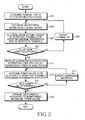
- FIGURE 2 illustrates an operation procedure of a base station in a distributed MIMO wireless communication system according to an exemplary embodiment of the present invention.
- FIGURE 2 illustrates a power control procedure for the case where the number of antennas per sector of a base station and the number of reception antennas of a terminal are 1, respectively.
- the base station determines a terminal set for a multiple access in step 201.
- the base station determines terminals that are to simultaneously receive signals through a multiple access.
- the base station shares the terminal set with other base stations participating in cooperative transmission. Therefore, the base station performs communication with the other base stations via a backhaul network, and shares information regarding the terminal set.
- the base station After determining the terminal set, the base station determines a beamforming matrix using a channel matrix between terminals included in the terminal set and base stations participating in the cooperative transmission in step 203.
- the beamforming matrix is a ZF beamforming matrix.
- the base station determines the beamforming matrix by determining an inverse matrix of the channel matrix.
- the base station does not use all of the beamforming matrix, but the base stations participating in the cooperative transmission divide and use the beamforming matrix on a column basis. That is, the base station uses one column of the beamforming matrix as a beamforming vector.
- the base station After determining the beamforming matrix, the base station determines minimum power values, that is, a minimum power set of the respective terminals for satisfying a minimum transmission rate of each terminal included in the terminal set in step 205. In other words, the base station determines the minimum power set using the minimum transmission rate of each terminal and the noise power experienced by each terminal. For example, the base station determines minimum power values of the respective terminals using Equation 7.
- the base station determines whether optimum power values for the respective terminals exist in step 207. That is, the base station determines whether a solution of a power optimization problem exists. At this point, the base station determines whether the optimum power values exist using minimum power values of the respective terminals, the beamforming matrix, and limit transmission power of the base station. That is, the base station determines sum of transmission powers with consideration of a power gain through the beamforming matrix, and then determines whether the sum of the transmission powers exceeds the limit transmission power of the base station. For example, the base station determines whether a constraint condition included in step 2 of Table 2 is met.
- the base station updates the terminal set in step 209, and returns to step 203.
- the terminal set is updated by removing one terminal. That is, the base station removes a terminal having a largest minimum power value, or removes a terminal having a largest power gain through the beamforming. For example, the base station selects a terminal to be removed using Equation 10 or 11.
- the base station transmits/receives information regarding the terminal to be removed via a backhaul network.
- the base station when optimum power values exist, the base station initializes a Lagrangian multiplier for a constraint condition for limit transmission power of the base station in step 211.
- the Lagrangian multiplier is for determining an optimization equation including the constraint condition in order to facilitate solving an optimization problem having a constraint condition. Since calculation of the Lagrangian multiplier is a widely known mathematical operation, description thereof is omitted.
- the base station After initializing the Lagrangian multiplier, the base station determines power values to be allocated to the respective terminals in step 213. That is, the base station determines a temporary power value using the Lagrangian multiplier, an element of a beamforming vector corresponding to a terminal k, and noise power experienced by the terminal k, and determines a larger one of the temporary power value and a minimum power value as a power value of the terminal k. That is, the base station performs the power value determination process on each terminal. For example, the base station determines power values to be allocated to the respective terminals using Equation 8.
- the base station determines whether the power values converge in step 215.
- whether the power values converge is determined depending on whether a difference between a power value re-determined by repeated update of the Lagrangian multiplier and a previous power value is smaller than a threshold. That is, the base station determines a difference value between a power value of a previous repetition step and a power value of a current repetition step, and then determines whether the difference value is smaller than the threshold.
- the base station determines the power values do not converge.
- the base station updates the Lagrangian multiplier in step 217.
- the base station updates the Lagrangian multiplier using a current Lagrangian multiplier, elements of the beamforming vector, and current power values of the respective terminals. For example, the base station updates the Lagrangian multiplier using Equation 9. After that, the base station returns to step 213.
- the base station completes power allocation and transmits data symbols according to the beamforming matrix and the power values in step 219.
- the base station multiplies data symbols to the respective terminals by the power values and a column vector of the beamforming matrix that corresponds to the base station, up-converts the multiplied data symbols into a Radio Frequency (RF) signal, and then transmits the RF signal via an antenna.
- RF Radio Frequency
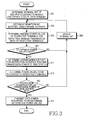
- FIGURE 3 illustrates an operation procedure of a base station in a distributed MIMO wireless communication system according to an exemplary embodiment of the present invention.
- FIGURE 3 illustrates a power control procedure for the case where a base station has a plurality of antennas per sector and a terminal has a plurality of reception antennas.
- the base station determines a terminal set for a multiple access, and stream sets in step 301.
- the base station determines terminals that are to simultaneously receive signals through a multiple access, and streams of respective terminals.
- the base station shares the terminal set and the stream sets with other base stations participating in cooperative transmission. Therefore, the base station communicates with the other base stations and shares information regarding the terminal set and the stream sets via a backhaul network.
- the base station determines beamforming matrixes using channel matrixes between terminals included in the terminal set and base stations participating in the cooperative transmission in step 303.
- the beamforming matrix is determined through a BD operation.
- the base station does not use all of the beamforming matrix, but the base stations participating in the cooperative transmission divide and use the beamforming matrix on a column basis. That is, the base station uses columns corresponding to transmission antennas of the base station of the beamforming matrix as a beamforming matrix.
- the base station After determining the beamforming matrixes, the base station determines minimum power values for each stream of respective terminals, that is, a minimum power set for satisfying a minimum transmission rate of the respective terminals included in the terminal set in step 305.
- the minimum power values are determined for each stream, and accordingly, each terminal has minimum power values as many as the number of streams of the terminal.
- the base station determines the minimum power set using power to be allocated by each base station to satisfy a minimum transmission rate of a terminal, a power gain for each stream of each terminal due to beamforming, noise power experienced by each terminal, and an effective channel gain of each terminal.
- the base station controls power that each base station allocates in order to satisfy a minimum transmission rate of a terminal, and determines optimum minimum power values. For example, the base station determines optimum power values as in Table 2. Detailed description is made with consideration of a terminal k.
- the base station initializes power that each base station allocates in order to satisfy a minimum transmission rate of a terminal k in step 0.
- the base station determines a Lagrangian multiplier for a constraint condition for the initialized power that each base station allocates in order to satisfy a minimum transmission rate of a terminal k, and then determines minimum power values for each stream using the Lagrangian multiplier, the power gain for each stream of each terminal due to beamforming, noise power experienced by the terminal k, and an effective channel gain of the terminal k in step "1."
- the base station determines an optimum transmission rate using the minimum power values, the effective channel gain of the terminal k, and the noise power experienced by the terminal k in step 2, and updates a minimum value and a maximum value of power to be allocated to satisfy the minimum transmission rate of the terminal k according to the optimum transmission rate and the minimum transmission rate in step 3.
- the base station re-determines the minimum power values by repeating the above-described process.
- the base station determines whether optimum power values for the respective terminals exist in step 307. That is, the base station determines whether a solution of a power optimization problem exists. At this point, the base station determines whether the optimum power values exist using the minimum power values for each stream of the respective terminals, the beamforming matrixes, and limit transmission power of the base station. That is, the base station determines a transmission power sum for the case where the minimum power values have been applied with consideration of a power gain through the beamforming matrixes, and then determines whether the transmission power sum exceeds limit transmission power of the base station. For example, the base station determines whether a constraint condition included in step 2 of Table 3 is met.
- the base station updates the terminal set in step 309, and returns to step 303.
- the terminal set is updated by removing one terminal.
- the base station selects a terminal having maximum power to be allocated by each base station to satisfy a minimum transmission rate of a terminal, as a terminal to be removed as in Equation 23.
- the base station transmits/receives information regarding a terminal to be removed via a backhaul network.
- the base station determines a Lagrangian multiplier for a constraint condition for limit transmission power of the base station, that is, a first constraint condition of Equation 21 in step 311.
- the Lagrangian multiplier is for determining an optimization equation including the constraint condition in order to facilitate solving an optimization problem having a constraint condition. Since calculation of the Lagrangian multiplier is a widely known mathematical operation, description thereof is omitted.
- the base station After determining the Lagrangian multiplier, the base station determines power values to be allocated to the respective terminals in step 313. That is, the base station determines a temporary power value using the Lagrangian multiplier, a power gain of an m-th stream of the terminal k due to beamforming, noise power experienced by the terminal k, and an effective channel gain of the m-th stream of the terminal k, and determines a larger one of the temporary power value and the minimum power value as a power value of the m-th stream of the terminal k. That is, the base station performs the power value determination process on each stream of each terminal. For example, the base station determines power values to be allocated to the respective terminals using Equation 22.
- the base station determines whether the power values meet a constraint condition for limit transmission power of the base station in step 315. At this point, the base station determines whether the optimum power values exist using minimum power values for each stream of the respective terminals, the beamforming matrixes, and the limit transmission power of the base station. That is, the base station determines a transmission power sum to the respective terminals with consideration of a power gain through the beamforming matrixes, and then determines whether the transmission power sum exceeds the limit transmission power of the base station. For example, the base station determines whether a constraint condition of Equation 22 is met. When the power values do not meet the constraint condition for the limit transmission power of the base station, the base station updates the terminal set in step 309, and returns to step 303.
- the base station completes power allocation and transmits data symbols according to the beamforming matrixes and the power values in step 317.
- the base station multiplies the data symbols to the respective terminals by the power values and column vectors of the beamforming matrix that correspond to the base station, up-converts the multiplied data symbols into an RF signal, and transmits the signal via an antenna.
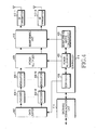
- FIGURE 4 illustrates a base station in a distributed MIMO wireless communication system according to an exemplary embodiment of the present invention.
- the base station includes a data buffer 402, a plurality of encoders 404-1 to 404-L, a plurality of modulators 406-1 to 406-L, a power multiplier 408, a beamforming unit 410, a plurality of RF transmitters 412-1 to 412-L, a backhaul communication unit 414, and a controller 416.
- the data buffer 402 stores data to be transmitted to terminals, and outputs the stored data under control of the controller 416.
- the plurality of encoders 404-1 to 404-L channel-encode a data bit line provided from the data buffer 402.
- the plurality of modulators 406-1 to 406-L generate complex symbols for each stream by modulating channel-encoded bit lines.
- the power multiplier 408 applies power values provided from the controller 416 to transmission symbols. That is, the power multiplier 408 receives power values of respective terminals from the controller 416, and multiplies transmission symbols of the respective terminals by corresponding power values.
- the beamforming unit 410 performs beamforming using a beamforming vector or a beamforming matrix provided from the controller 416. That is, the beamforming unit 410 receives the beamforming vector or the beamforming matrix from the controller 416, and multiplies the transmission symbols of the respective terminals by a corresponding element of the beamforming vector or the beamforming matrix.
- the plurality of RF transmitters 412-1 to 412-L up-convert beamformed transmission signals into RF signals, and then transmit the signals via a plurality of transmission antennas.
- the backhaul communication unit 414 provides an interface for communication with other base stations participating in cooperative transmission. More particularly, to share a terminal set including multiple accessing terminals, the backhaul communication unit 414 transmits/receives information for sharing the terminal set with the base station participating in the cooperative transmission via a backhaul network.
- the controller 416 controls an overall function of the base station.
- the controller 416 includes a scheduler 418, a beamforming matrix calculator 420, and a power allocator 422.
- the scheduler 418 determines terminals for a multiple access, and allocates a resource to the terminals.
- the beamforming matrix calculator 420 determines a beamforming matrix for processing transmission signals to the terminals.
- the power allocator 422 determines transmission power values for the terminals within limit transmission power. Detailed operations of the scheduler 418, the beamforming matrix calculator 420, and the power allocator 422 change depending on an exemplary embodiment of the present invention, and operations according to each embodiment is described below.
- the scheduler 418 determines a terminal set of multiple accessing terminals, and provides the terminal set information to the beamforming matrix calculator 420.
- the beamforming matrix calculator 420 determines a beamforming matrix using a channel matrix between terminals included in the terminal set and base stations participating in the cooperative transmission.
- the beamforming matrix is a ZF beamforming matrix.
- the beamforming matrix calculator 420 determines the beamforming matrix by determining an inverse matrix of the channel matrix.
- the beamforming matrix calculator 420 provides the beamforming matrix information to the power allocator 422. Subsequently, the power allocator 422 determines power values for the terminals.
- the power allocator 422 determines minimum power values, that is, a minimum power set for satisfying a minimum transmission rate of respective terminals included in the terminal set, and determines whether optimum power values exist using the minimum power values. That is, the power allocator 422 determines a transmission power sum with consideration of a power gain through the beamforming matrix, and determines whether the transmission power sum exceeds limit transmission power of the power allocator 422. When the optimum power values do not exist, the power allocator 422 informs the scheduler 418 that optimum power values do not exist, and the scheduler 418 updates the terminal set by removing a terminal having a largest minimum power value, or removing a terminal having a largest power gain through the beamforming.
- the power allocator 422 initializes a Lagrangian multiplier for a constraint condition for limit transmission power of the base station, and then determines power values to be allocated to the respective terminals as in Equation 8. At this point, the calculation of the power values is repeated until the power values converge. In every repetition step, the Lagrangian multiplier is updated as in Equation 9.
- the scheduler 418 instructs the data buffer 402 to output transmission data to terminals included in a current terminal set, and the beamforming matrix calculator 420 provides a beamforming vector or a beamforming matrix to the beamforming unit 410, and the power allocator 422 provides power values to the power multiplier 408.
- the scheduler 418 determines a terminal set of multiple accessing terminals, and stream sets, and provides the terminal set information and the stream set information to the beamforming matrix calculator 420.
- the beamforming matrix calculator 420 determines beamforming matrixes using channel matrixes between terminals included in the terminal set and base stations participating in the cooperative transmission. For example, the beamforming matrix is determined through a BD operation.
- the beamforming matrix calculator 420 provides the beamforming matrix information to the power allocator 422. Subsequently, the power allocator 422 determines power values for each stream for the terminals.
- the power allocator 422 determines minimum power values for each stream of respective terminals, that is, a minimum power set for satisfying a minimum transmission rate of the respective terminals included in the terminal set, and determines whether optimum power values exist using the minimum power values. That is, the power allocator 422 determines a transmission power sum for the case where the minimum power values have been applied with consideration of a power gain through the beamforming matrixes, and then determines whether the transmission power sum exceeds limit transmission power of the power allocator 422. When the optimum power values do not exist, the power allocator 422 informs the scheduler that the optimum power values do not exist, and the scheduler 418 updates the terminal set by removing a terminal selected through Equation (23).
- the power allocator 422 determines a Lagrangian multiplier for a constraint condition for limit transmission power of the base station, that is, a first constraint condition of Equation 21, and then determines power values to be allocated to respective terminals as in Equation 22. In addition, the power allocator 422 determines whether the power values meet a constraint condition for limit transmission power of the base station, that is, a constraint condition of Equation 22. When the constraint condition is not met, the power allocator 422 informs the scheduler 418 that the constraint condition is not met, and the scheduler 418 updates the terminal set by removing a terminal selected through Equation 23.
- the scheduler 418 instructs the data buffer 402 to output transmission data to terminals included in a current terminal set, and the beamforming matrix calculator 420 provides a beamforming vector or a beamforming matrix to the beamforming unit 410, and the power allocator 422 provides power values to the power multiplier 408.
- the power allocator 422 controls power that each base station allocates in order to satisfy a minimum transmission rate of a terminal, and determines optimum minimum power values. Detailed description is made with consideration of a terminal k.
- the power allocator 422 initializes power that each base station allocates in order to satisfy a minimum transmission rate of a terminal k in step 0 of Table 2.
- the power allocator 422 determines a Lagrangian multiplier for a constraint condition for the initialized power that each base station allocates in order to satisfy a minimum transmission rate of a terminal k, and then determines minimum power values for each stream using the Lagrangian multiplier, the power gain for each stream of each terminal due to beamforming, noise power experienced by the terminal k, and an effective channel gain of the terminal k in step 1.
- the power allocator 422 determines an optimum transmission rate using the minimum power values, the effective channel gain of the terminal k, and the noise power experienced by the terminal k in step 2, and updates a minimum value and a maximum value of power to be allocated to satisfy the minimum transmission rate of the terminal k according to the optimum transmission rate and the minimum transmission rate in step 3. At this point, when a difference value between the optimum transmission rate and the minimum transmission rate is equal to or greater than a threshold, the power allocator 422 re-determines the minimum power values by repeating the above-described process.
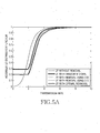
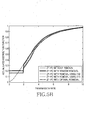
- FIGURES 5A to 5C illustrate performance of a distributed MIMO wireless communication system according to an exemplary embodiment of the present invention.
- FIGURES 5A to 5C illustrate simulated experiment results for a distributed MIMO wireless communication system according to an exemplary embodiment of the present invention.
- a communication environment assumed in the simulated experiment is described in Table 5.
- FIGURE 5A illustrates an accumulated distribution of a data transmission rate per unit bandwidth of each terminal when various terminal set management technique is applied in the case where a terminal has a single reception antenna.
- an optimal removal denotes an optimal terminal set removal technique for removing a terminal in order to meet a constraint condition for a minimum transmission rate of a terminal.
- the optimal terminal set is determined with consideration of the number of all cases that may be removed.
- a terminal that does not meet a minimum transmission rate of 2 bps/Hz exists at the rate of about 50%.
- a rate of a terminal that does not meet the minimum transmission rate reduces up to 20% at the maximum. More particularly, when a terminal removal rule of Equation 11, that is, a rule of removing a terminal having a largest power loss or a smallest effective channel gain is applied, a performance that approaches an optimal technique in an aspect of a system yield is achieved.
- FIGURE 5B illustrates a transmission rate accumulated distribution of each terminal when a Power Control (PC) technique proposed after a terminal set management technique is applied is applied.
- PC Power Control
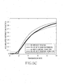
- FIGURE 5C illustrates performance comparison when a BD beamforming is applied, a terminal set management technique and a PC technique are applied in the case where a terminal and a base station have two antennas, respectively.
- 'BD without removal' denotes the case where the same power is allocated to data streams of each terminal and a terminal set management technique is not applied
- 'BD-PC without removal' denotes the case where a PC technique for maximizing a system yield is applied.
- a transmission rate accumulated distribution of terminals when the same power is allocated, a terminal that does not meet the minimum transmission rate exists at the rate of about 12%.
- a rate of a terminal that does not meet the minimum transmission rate reduces to 7% or less. Similar to a performance gain by a terminal set management technique for the case of the above ZF-PC, a BD-PC terminal group management technique provides a performance effect of reducing a transmission-not-allowed probability while not reducing a system yield.
- a distributed MIMO wireless communication prevents a phenomenon that a terminal does not meet a minimum transmission rate as much as possible through a power control with consideration of limit transmission power for each base station, so that users may receive various large capacity services.
Landscapes
- Engineering & Computer Science (AREA)
- Computer Networks & Wireless Communication (AREA)
- Signal Processing (AREA)
- Power Engineering (AREA)
- Mobile Radio Communication Systems (AREA)
Claims (16)
- Verfahren zum Regeln der Leistung einer Basisstation (115), die an kooperativer Übertragung in einem drahtlosen Mehrfacheingang/Mehrfachausgang- (Multiple Input Multiple Output, MIMO) Kommunikationssystem beteiligt ist, wobei das Verfahren umfasst:Ermitteln (203, 303) wenigstens einer Beamforming-Matrix zur Verarbeitung von Übertragungssignalen an in einem Endgerätesatz für einen mehrfachen Zugang enthaltene Endgeräte,Ermitteln (205, 305) von Mindestleistungswerten, die zur Gewährleistung einer Mindestübertragungsrate der Endgeräte erforderlich sind,Ermitteln (207, 307) unter Verwendung der Mindestleistungswerte, der Beamforming-Matrix und eines Übertragungsleistungsgrenzwerts der Basisstation (115), ob optimale Leistungswerte bestehen, und,wenn die optimalen Leistungswerte bestehen, Ermitteln (213, 313) von Übertragungsleistungswerten für jeweilige Endgeräte in einem Bereich, der dem Übertragungsleistungsgrenzwert der Basisstation (115) gerecht wird.
- Verfahren nach Anspruch 1, ferner umfassend, wenn die optimalen Leistungswerte nicht bestehen, das Entfernen (209, 309) von einem Endgerät mit dem größten Mindestleistungswert, einem Endgerät mit einer größten Leistungsverstärkung durch Beamforming oder einem Endgerät mit der größten Leistung, die jede Basisstation (115, 125, 135) zuzuweisen hat, um eine Mindestübertragungsrate zu gewährleisten, aus dem Endgerätesatz.
- Verfahren nach Anspruch 2, wobei das Ermitteln (305) der Mindestleistungswerte das Ermitteln von einem Mindestleistungswert pro Endgerät unter Verwendung von Rauschleistungen, die von den jeweiligen Endgeräten erfahren werden, und von Mindestübertragungsraten der jeweiligen Endgeräte umfasst.
- Verfahren nach Anspruch 3, wobei das Ermitteln (307), ob die optimalen Leistungswerte bestehen, umfasst:Ermitteln einer Übertragungsleistungssumme für einen Fall der Verwendung der Mindestübertragungsleistung unter Berücksichtigung einer Leistungsverstärkung durch die Beamforming-Matrix undErmitteln, ob die Übertragungsleistungssumme den Übertragungsleistungsgrenzwert übersteigt.
- Verfahren nach Anspruch 4, wobei das Ermitteln der Übertragungsleistungswerte umfasst:Ermitteln (213) eines provisorischen Leistungswerts des Endgeräts unter Verwendung eines Lagrange-Multiplikators für eine Beschränkungsbedingung für den Übertragungsleistungsgrenzwert, der Beamforming-Matrix und der von einem Endgerät erfahrenen Rauschleistung;Ermitteln eines Größeren des provisorischen Leistungswerts und eines Mindestleistungswerts des Endgeräts als einen Leistungswert des Endgeräts;Aktualisieren (217) des Lagrange-Multiplikators unter Verwendung des Leistungswerts, des Lagrange-Multiplikators und der Beamforming-Matrix;Neuermitteln (213) eines Übertragungsleistungswerts des Endgeräts unter Verwendung des aktualisierten Lagrange-Multiplikators und,wenn ein Übertragungsleistungswert des Endgeräts konvergiert, Abschließen der Übertragungsleistungszuweisung für das Endgerät.
- Verfahren nach Anspruch 2, wobei das Ermitteln (305) der Mindestleistungswerte das Ermitteln so vieler Mindestleistungswerte wie die Anzahl von Strömen pro Endgerät unter Verwendung der von jeweiligen Endgeräten erfahrenen Rauschleistungen, Mindestübertragungsraten der jeweiligen Endgeräte, Leistung, die jede Basisstation (115, 125, 135) zuzuweisen hat, um eine Mindestübertragungsrate eines Endgeräts zu gewährleisten, Leistungsverstärkungen für jeden Strom der jeweiligen Endgeräte aufgrund von Beamforming und effektiven Kanalverstärkungen der jeweiligen Endgeräte.
- Verfahren nach Anspruch 6, wobei das Ermitteln (307), ob die optimalen Leistungswerte bestehen, umfasst:Ermitteln einer Übertragungsleistungssumme für einen Fall der Verwendung der Mindestübertragungsleistung unter Berücksichtigung einer Leistungsverstärkung durch die Beamforming-Matrix undErmitteln, ob die Übertragungsleistungssumme den Übertragungsleistungsgrenzwert überschreitet.
- Verfahren nach Anspruch 7, wobei das Ermitteln der Übertragungsleistungswerte umfasst:Ermitteln provisorischer Leistungswerte für jeden Strom der Endgeräte unter Verwendung der Lagrange-Multiplikators für die Beschränkungsbedingung für den Übertragungsleistungsgrenzwert, Leistungsverstärkungen für jeden Strom der Endgeräte aufgrund von Beamforming, von den Endgeräten erfahrenen Rauschleistungen und effektiven Kanalverstärkungen für jeden Strom der Endgeräte, andErmitteln eines Größeren des provisorischen Leistungswerts und des Mindestleistungswert als Übertragungsleistungswerte für jeden Strom der Endgeräte.
- Vorrichtung (416) einer Basisstation (115), die an kooperativer Übertragung in einem drahtlosen Mehrfacheingang/Mehrfachausgang- (Multiple Input Multiple Output, MIMO) Kommunikationssystem beteiligt ist, wobei die Vorrichtung (416) umfasst:einen Rechner (420) zum Ermitteln von wenigstens einer Beamforming-Matrix zur Verarbeitung von Übertragungssignalen an in einem Endgerätesatz für einen mehrfachen Zugang enthaltene Endgeräte, undeinen Zuteiler (422) zum Ermitteln von Mindestleistungswerten, die zur Gewährleistung einer Mindestübertragungsgeschwindigkeit der Endgeräte erforderlich sind, Ermitteln unter Verwendung der Mindestleistungswerte, der Beamforming-Matrix und eines Übertragungsleistungsgrenzwerts einer Basisstation, ob optimale Leistungswerte bestehen, und, wenn die optimalen Leistungswerte bestehen, Ermitteln von Übertragungsleistungswerten für jeweilige Endgeräte in einem Bereich, der dem Übertragungsleistungsgrenzwert der Basisstation (115) gerecht wird.
- Vorrichtung nach Anspruch 9, ferner umfassend einen Scheduler (418) zum Entfernen von einem Endgerät mit dem größten Mindestleistungswert, einem Endgerät mit einer größten Leistungsverstärkung durch Beamforming oder einem Endgerät mit der größten Leistung, die jede Basisstation (115, 125, 135) zuzuweisen hat, um eine Mindestübertragungsrate zu gewährleisten, aus dem Endgerätesatz, wenn die optimalen Leistungswerte nicht bestehen.
- Vorrichtung nach Anspruch 10, wobei die Vorrichtung ausgeführt ist zum Ermitteln der Mindestleistungswerte durch Ermitteln von einem Mindestleistungswert pro Endgerät unter Verwendung von Rauschleistungen, die von den jeweiligen Endgeräten erlebt werden, und Mindestübertragungsraten der jeweiligen Endgeräte.
- Vorrichtung nach Anspruch 11, wobei die Vorrichtung ausgeführt ist zum Ermitteln, ob die optimalen Leistungswerte bestehen, durch:Ermitteln einer Übertragungsleistungssumme für einen Fall der Verwendung der Mindestübertragungsleistung unter Berücksichtigung einer Leistungsverstärkung durch die Beamforming-Matrix undErmitteln, ob die Übertragungsleistungssumme den Übertragungsleistungsgrenzwert übersteigt.
- Vorrichtung nach Anspruch 12, wobei die Vorrichtung ausgeführt ist zum Ermitteln der Übertragungsleistungswerte durch:Ermitteln eines provisorischen Leistungswerts des Endgeräts unter Verwendung eines Lagrange-Multiplikators für eine Beschränkungsbedingung für den Übertragungsleistungsgrenzwert, der Beamforming-Matrix und der von einem Endgerät erfahrenen Rauschleistung;Ermitteln eines Größeren des provisorischen Leistungswerts und eines Mindestleistungswerts des Endgeräts als einen Leistungswert des Endgeräts;Aktualisieren des Lagrange-Multiplikators unter Verwendung des Leistungswerts, des Lagrange-Multiplikators und der Beamforming-Matrix; undNeuermitteln eines Übertragungsleistungswerts des Endgeräts unter Verwendung des aktualisierten Lagrange-Multiplikators und,wobei die Vorrichtung ferner ausgeführt ist zum Abschließen der Übertragungsleistungszuweisung für das Endgerät, wenn ein Übertragungsleistungswert des Endgeräts konvergiert.
- Vorrichtung nach Anspruch 10, wobei die Vorrichtung ausgeführt ist zum Ermitteln so vieler Mindestleistungswerte wie die Anzahl von Strömen pro Endgerät unter Verwendung der von jeweiligen Endgeräten erfahrenen Rauschleistungen, Mindestübertragungsraten der jeweiligen Endgeräte, Leistung, die jede Basisstation (115, 125, 135) zuzuweisen hat, um eine Mindestübertragungsrate eines Endgeräts zu gewährleisten, Leistungsverstärkungen für jeden Strom der jeweiligen Endgeräte aufgrund von Beamforming und effektiven Kanalverstärkungen der jeweiligen Endgeräte.
- Vorrichtung nach Anspruch 14, wobei die Vorrichtung ausgeführt ist zum Ermitteln, ob die optimalen Leistungswerte bestehen, durch:Ermitteln einer Übertragungsleistungssumme für einen Fall der Verwendung der Mindestübertragungsleistung unter Berücksichtigung einer Leistungsverstärkung durch die Beamforming-Matrix undErmitteln, ob die Übertragungsleistungssumme den Übertragungsleistungsgrenzwert übersteigt.
- Vorrichtung nach Anspruch 15, wobei die Vorrichtung ausgeführt ist zum Ermitteln der Übertragungsleistungswerte durch:Ermitteln provisorischer Leistungswerte für jeden Strom der Endgeräte unter Verwendung des Lagrange-Multiplikators für die Beschränkungsbedingung für den Übertragungsleistungsgrenzwert, Leistungsverstärkungen für jeden Strom der Endgeräte aufgrund von Beamforming, der von den Endgeräten erfahrenen Rauschleistungen und effektiven Kanalverstärkungen für jeden Strom der Endgeräte undErmitteln eines Größeren des provisorischen Leistungswerts und des Mindestleistungswerts des Endgeräts als Übertragungsleistungswerte für jeden Strom der Endgeräte.
Applications Claiming Priority (1)
| Application Number | Priority Date | Filing Date | Title |
|---|---|---|---|
| KR1020090031743A KR101527110B1 (ko) | 2009-04-13 | 2009-04-13 | 분산 다중 입출력 무선통신 시스템에서 전력 제어 장치 및 방법 |
Publications (2)
| Publication Number | Publication Date |
|---|---|
| EP2242189A1 EP2242189A1 (de) | 2010-10-20 |
| EP2242189B1 true EP2242189B1 (de) | 2015-09-16 |
Family
ID=42359521
Family Applications (1)
| Application Number | Title | Priority Date | Filing Date |
|---|---|---|---|
| EP10156960.6A Not-in-force EP2242189B1 (de) | 2009-04-13 | 2010-03-18 | Vorrichtung und Verfahren zur Steuerung der Leistung in verteilten drahtlosen Mehrfacheingabe-Mehrfachausgabe-Kommunikationssystem |
Country Status (4)
| Country | Link |
|---|---|
| US (1) | US8818440B2 (de) |
| EP (1) | EP2242189B1 (de) |
| KR (1) | KR101527110B1 (de) |
| CN (1) | CN101860951B (de) |
Families Citing this family (26)
| Publication number | Priority date | Publication date | Assignee | Title |
|---|---|---|---|---|
| EP2566266B1 (de) * | 2010-04-27 | 2018-07-11 | Fujitsu Limited | Drahtloses kommunikationsverfahren, drahtlose basisstation, mobiles endgerät und drahtloses kommunikationssystem |
| BR112013002605B1 (pt) | 2011-02-18 | 2022-08-23 | Sun Patent Trust | Método de transmissão, aparelho de transmissão, método de recepção e aparelho de recepção |
| CN102158321A (zh) * | 2011-04-28 | 2011-08-17 | 西安交通大学 | 一种能够提高移动通信系统功率效率的分布式mimo系统中功率分配与天线选择方法 |
| KR20120126572A (ko) | 2011-05-12 | 2012-11-21 | 한국전자통신연구원 | 다중 사용자 다중 입출력 인지 무선 통신 시스템에서 인지 무선 기지국 및 인지 무선 기지국의 통신 방법 및 장치 |
| KR20130104369A (ko) * | 2012-03-13 | 2013-09-25 | 삼성전자주식회사 | 협력 전송 기반의 다중 안테나 시스템에서의 전송 파워 결정 방법 |
| CN102802245A (zh) * | 2012-07-19 | 2012-11-28 | 重庆大学 | 一种mimo网络的功率管理方法 |
| CN103905162B (zh) * | 2012-12-27 | 2017-06-16 | 华为技术有限公司 | 一种系统功率分配方法和设备 |
| KR101616636B1 (ko) * | 2014-10-16 | 2016-04-28 | 영남대학교 산학협력단 | 듀얼 모드 빔포밍 방법 및 장치 |
| KR101591964B1 (ko) | 2015-02-24 | 2016-02-05 | 가천대학교 산학협력단 | 무선통신시스템 분산 제어 방법 및 장치 |
| KR101675484B1 (ko) * | 2015-05-19 | 2016-11-11 | 가천대학교 산학협력단 | 무선통신시스템의 기지국 동작 제어 방법 |
| CN107205274B (zh) * | 2016-03-17 | 2019-09-17 | 北京邮电大学 | 资源分配值计算方法及装置 |
| CN107889153B (zh) * | 2016-09-30 | 2021-08-17 | 中国电信股份有限公司 | 用于降低终端能耗的方法和装置 |
| US10630434B2 (en) | 2017-02-01 | 2020-04-21 | Electronics And Telecommunications Research Institute | Operation method of communication node for supporting coordinated multi-point transmission and reception in communication network |
| KR102660492B1 (ko) * | 2017-02-21 | 2024-04-25 | 삼성전자 주식회사 | 무선 통신 시스템에서 기지국, 단말 및 이의 제어 방법 |
| EP3668199B1 (de) * | 2017-08-11 | 2026-01-14 | LG Electronics Inc. | Einstellung der sendeleistung für mehrere ccs während der trägeraggregation in einem drahtlosen kommunikationssystem |
| KR102543091B1 (ko) * | 2018-06-15 | 2023-06-14 | 삼성전자주식회사 | 무선 통신 시스템에서 통합형 빔포밍을 위한 장치 및 방법 |
| KR102000667B1 (ko) * | 2018-09-27 | 2019-07-16 | 삼성전자주식회사 | 협력 전송 기반의 다중 안테나 시스템에서의 전송 파워 결정 방법 |
| CN112491456A (zh) * | 2019-09-11 | 2021-03-12 | 索尼公司 | 电子设备、无线通信方法和计算机可读存储介质 |
| CN111107642B (zh) * | 2019-12-13 | 2022-04-15 | 南京航空航天大学 | 适于无线网络的资源分配方法、装置和系统 |
| CN112584403B (zh) * | 2020-11-02 | 2022-11-01 | 河南理工大学 | Noma小小区最大速率最小功率的联合优化方法 |
| CN112632846B (zh) * | 2020-11-13 | 2023-10-24 | 国网浙江省电力有限公司绍兴供电公司 | 一种电力系统输电断面极限概率评估方法及电子设备 |
| CN112702094B (zh) * | 2020-12-21 | 2022-02-11 | 杭州电子科技大学 | 基于可调精度adc的大规模mimo系统能效优化方法 |
| CN114337751B (zh) * | 2021-12-07 | 2023-11-21 | 江苏华鹏智能仪表科技股份有限公司 | 一种时间反转ofdm多用户通信系统的功率分配方法 |
| CN115459817B (zh) * | 2022-07-21 | 2023-08-01 | 电子科技大学 | 基于非合作博弈的合作式mimo雷达通信一体化系统功率分配方法 |
| KR102688643B1 (ko) * | 2022-11-29 | 2024-07-25 | 재단법인대구경북과학기술원 | 빔포밍 스케쥴링 장치 및 방법 |
| CN120074612B (zh) * | 2025-04-23 | 2025-09-02 | 浙江大学 | 一种感知辅助的通信干扰一体化鲁棒波束成形设计方法 |
Family Cites Families (6)
| Publication number | Priority date | Publication date | Assignee | Title |
|---|---|---|---|---|
| US7719993B2 (en) * | 2004-12-30 | 2010-05-18 | Intel Corporation | Downlink transmit beamforming |
| KR100946924B1 (ko) | 2005-06-24 | 2010-03-09 | 삼성전자주식회사 | 제로 포싱 빔포밍 알고리즘에서의 사용자 단말 선택 방법 |
| US7813293B2 (en) * | 2006-05-12 | 2010-10-12 | John Papandriopoulos | Method for distributed spectrum management of digital communications systems |
| ES2325713B1 (es) * | 2007-06-22 | 2010-06-22 | Fundacion Privada Centre Tecnologic De Telecomunicacions De Catalunya | Procedimiento de asignacion de potencia en sistemas multiantena bajo conocimiento parcial del canal. |
| CN101340218A (zh) | 2007-07-04 | 2009-01-07 | 华为技术有限公司 | 多输入多输出系统中通信方法及装置 |
| US20090323849A1 (en) * | 2008-06-30 | 2009-12-31 | Interdigital Patent Holdings, Inc. | Method and apparatus for performing multiple-input multiple-output wireless communications |
-
2009
- 2009-04-13 KR KR1020090031743A patent/KR101527110B1/ko not_active Expired - Fee Related
-
2010
- 2010-03-18 EP EP10156960.6A patent/EP2242189B1/de not_active Not-in-force
- 2010-03-23 US US12/661,759 patent/US8818440B2/en active Active
- 2010-04-13 CN CN201010164500.0A patent/CN101860951B/zh not_active Expired - Fee Related
Also Published As
| Publication number | Publication date |
|---|---|
| US20100261498A1 (en) | 2010-10-14 |
| CN101860951A (zh) | 2010-10-13 |
| EP2242189A1 (de) | 2010-10-20 |
| CN101860951B (zh) | 2014-04-09 |
| US8818440B2 (en) | 2014-08-26 |
| KR101527110B1 (ko) | 2015-06-16 |
| KR20100113262A (ko) | 2010-10-21 |
Similar Documents
| Publication | Publication Date | Title |
|---|---|---|
| EP2242189B1 (de) | Vorrichtung und Verfahren zur Steuerung der Leistung in verteilten drahtlosen Mehrfacheingabe-Mehrfachausgabe-Kommunikationssystem | |
| KR100980647B1 (ko) | 다중 안테나 시스템에서 간섭 제거 장치 및 방법 | |
| KR101859821B1 (ko) | 밀리미터파 하향링크 채널에서 디지털-아날로그 하이브리드 빔포밍 방법 및 시스템 | |
| US6987819B2 (en) | Method and device for multiple input/multiple output transmit and receive weights for equal-rate data streams | |
| EP2380300B1 (de) | Verfahren und anordnungen zum rückmelden von kanalzustandsinformationen | |
| US20080102881A1 (en) | Method and apparatus for adaptively allocating transmission power for beam-forming combined with OSTBCs in a distributed wireless communication system | |
| EP2062378B1 (de) | Strahlenerzeugung mit unvollkommener nachricht über den zustand des kabels | |
| EP1739852A1 (de) | Verfahren für mehrere eingänge und mehrere ausgänge (mimo) auf der basis einer verteilten übertragungsquelle in einem zentralisierten basisstationssystem | |
| US7983710B2 (en) | Method of coordinated wireless downlink transmission | |
| KR20090023879A (ko) | 다중 사용자 다중 입출력 무선통신 시스템에서 간섭 제거를위한 신호 처리 장치 및 방법 | |
| US20070218950A1 (en) | Data transmission parameter optimization in MIMO communications system | |
| US8380212B2 (en) | Apparatus and method for transmission of dynamic feedback channel information in a MIMO system | |
| CN101359950A (zh) | 一种基于奇异值分解迫零波束成型的多天线中继传输方法 | |
| EP3403364B1 (de) | Vorrichtung und verfahren zur verwaltung einer vollduplex-kommunikation zwischen einer basisstation und einer vielzahl an benutzergeräten | |
| WO2019069410A1 (en) | REMOTE RADIO HEAD, BEAM FORMING METHOD, AND STORAGE MEDIUM | |
| KR102159576B1 (ko) | 핑거프린트 기반의 빔 간섭 제거 시스템 및 방법 | |
| Darabi et al. | Active IRS design for RSMA-based downlink URLLC transmission | |
| EP3793095B1 (de) | Verfahren und system zum optimalen räumlichen multiplexen in drahtloskommunikationssystemen mit mehreren antennen unter verwendung von mu-mimo-techniken | |
| EP2814192B1 (de) | Verfahren, vorrichtung und system zur signalübertragung | |
| KR102805538B1 (ko) | 빔포밍 신호 송수신 방법 및 이를 구현하기 위한 신호 송수신 장치 | |
| KR101662316B1 (ko) | 다중 입출력 통신 시스템에서 데이터를 송수신하는 방법 및 장치 | |
| KR20100028859A (ko) | 다중 입출력 무선통신 시스템에서 적응적 코드북 컬러링 장치 및 방법 | |
| KR102664971B1 (ko) | 에너지 공급이 제한된 기지국이 심층강화학습을 기반으로 합 전송률 최대화를 수행하기 위한 전송률 분할 다중접속 방법 | |
| JP4358241B2 (ja) | 空間多重伝送用送信方法及び送信装置 | |
| JP4593489B2 (ja) | 無線通信方法及び無線通信装置 |
Legal Events
| Date | Code | Title | Description |
|---|---|---|---|
| PUAI | Public reference made under article 153(3) epc to a published international application that has entered the european phase |
Free format text: ORIGINAL CODE: 0009012 |
|
| AK | Designated contracting states |
Kind code of ref document: A1 Designated state(s): AT BE BG CH CY CZ DE DK EE ES FI FR GB GR HR HU IE IS IT LI LT LU LV MC MK MT NL NO PL PT RO SE SI SK SM TR |
|
| AX | Request for extension of the european patent |
Extension state: AL BA ME RS |
|
| 17P | Request for examination filed |
Effective date: 20110415 |
|
| RAP1 | Party data changed (applicant data changed or rights of an application transferred) |
Owner name: INDUSTRY-UNIVERSITY COOPERATION FOUNDATION SOGANG Owner name: SAMSUNG ELECTRONICS CO., LTD. |
|
| GRAP | Despatch of communication of intention to grant a patent |
Free format text: ORIGINAL CODE: EPIDOSNIGR1 |
|
| RIC1 | Information provided on ipc code assigned before grant |
Ipc: H04B 7/04 20060101ALN20150422BHEP Ipc: H04W 52/40 20090101ALN20150422BHEP Ipc: H04B 7/06 20060101AFI20150422BHEP |
|
| INTG | Intention to grant announced |
Effective date: 20150513 |
|
| GRAS | Grant fee paid |
Free format text: ORIGINAL CODE: EPIDOSNIGR3 |
|
| GRAA | (expected) grant |
Free format text: ORIGINAL CODE: 0009210 |
|
| AK | Designated contracting states |
Kind code of ref document: B1 Designated state(s): AT BE BG CH CY CZ DE DK EE ES FI FR GB GR HR HU IE IS IT LI LT LU LV MC MK MT NL NO PL PT RO SE SI SK SM TR |
|
| REG | Reference to a national code |
Ref country code: GB Ref legal event code: FG4D |
|
| REG | Reference to a national code |
Ref country code: CH Ref legal event code: EP |
|
| REG | Reference to a national code |
Ref country code: IE Ref legal event code: FG4D |
|
| REG | Reference to a national code |
Ref country code: AT Ref legal event code: REF Ref document number: 750519 Country of ref document: AT Kind code of ref document: T Effective date: 20151015 |
|
| REG | Reference to a national code |
Ref country code: DE Ref legal event code: R096 Ref document number: 602010027514 Country of ref document: DE |
|
| REG | Reference to a national code |
Ref country code: NL Ref legal event code: MP Effective date: 20150916 |
|
| PG25 | Lapsed in a contracting state [announced via postgrant information from national office to epo] |
Ref country code: FI Free format text: LAPSE BECAUSE OF FAILURE TO SUBMIT A TRANSLATION OF THE DESCRIPTION OR TO PAY THE FEE WITHIN THE PRESCRIBED TIME-LIMIT Effective date: 20150916 Ref country code: LV Free format text: LAPSE BECAUSE OF FAILURE TO SUBMIT A TRANSLATION OF THE DESCRIPTION OR TO PAY THE FEE WITHIN THE PRESCRIBED TIME-LIMIT Effective date: 20150916 Ref country code: GR Free format text: LAPSE BECAUSE OF FAILURE TO SUBMIT A TRANSLATION OF THE DESCRIPTION OR TO PAY THE FEE WITHIN THE PRESCRIBED TIME-LIMIT Effective date: 20151217 Ref country code: LT Free format text: LAPSE BECAUSE OF FAILURE TO SUBMIT A TRANSLATION OF THE DESCRIPTION OR TO PAY THE FEE WITHIN THE PRESCRIBED TIME-LIMIT Effective date: 20150916 Ref country code: NO Free format text: LAPSE BECAUSE OF FAILURE TO SUBMIT A TRANSLATION OF THE DESCRIPTION OR TO PAY THE FEE WITHIN THE PRESCRIBED TIME-LIMIT Effective date: 20151216 |
|
| REG | Reference to a national code |
Ref country code: LT Ref legal event code: MG4D |
|
| REG | Reference to a national code |
Ref country code: AT Ref legal event code: MK05 Ref document number: 750519 Country of ref document: AT Kind code of ref document: T Effective date: 20150916 |
|
| PG25 | Lapsed in a contracting state [announced via postgrant information from national office to epo] |
Ref country code: HR Free format text: LAPSE BECAUSE OF FAILURE TO SUBMIT A TRANSLATION OF THE DESCRIPTION OR TO PAY THE FEE WITHIN THE PRESCRIBED TIME-LIMIT Effective date: 20150916 Ref country code: SE Free format text: LAPSE BECAUSE OF FAILURE TO SUBMIT A TRANSLATION OF THE DESCRIPTION OR TO PAY THE FEE WITHIN THE PRESCRIBED TIME-LIMIT Effective date: 20150916 |
|
| PG25 | Lapsed in a contracting state [announced via postgrant information from national office to epo] |
Ref country code: NL Free format text: LAPSE BECAUSE OF FAILURE TO SUBMIT A TRANSLATION OF THE DESCRIPTION OR TO PAY THE FEE WITHIN THE PRESCRIBED TIME-LIMIT Effective date: 20150916 |
|
| PG25 | Lapsed in a contracting state [announced via postgrant information from national office to epo] |
Ref country code: ES Free format text: LAPSE BECAUSE OF FAILURE TO SUBMIT A TRANSLATION OF THE DESCRIPTION OR TO PAY THE FEE WITHIN THE PRESCRIBED TIME-LIMIT Effective date: 20150916 Ref country code: CZ Free format text: LAPSE BECAUSE OF FAILURE TO SUBMIT A TRANSLATION OF THE DESCRIPTION OR TO PAY THE FEE WITHIN THE PRESCRIBED TIME-LIMIT Effective date: 20150916 Ref country code: SK Free format text: LAPSE BECAUSE OF FAILURE TO SUBMIT A TRANSLATION OF THE DESCRIPTION OR TO PAY THE FEE WITHIN THE PRESCRIBED TIME-LIMIT Effective date: 20150916 Ref country code: IS Free format text: LAPSE BECAUSE OF FAILURE TO SUBMIT A TRANSLATION OF THE DESCRIPTION OR TO PAY THE FEE WITHIN THE PRESCRIBED TIME-LIMIT Effective date: 20160116 Ref country code: IT Free format text: LAPSE BECAUSE OF FAILURE TO SUBMIT A TRANSLATION OF THE DESCRIPTION OR TO PAY THE FEE WITHIN THE PRESCRIBED TIME-LIMIT Effective date: 20150916 Ref country code: EE Free format text: LAPSE BECAUSE OF FAILURE TO SUBMIT A TRANSLATION OF THE DESCRIPTION OR TO PAY THE FEE WITHIN THE PRESCRIBED TIME-LIMIT Effective date: 20150916 |
|
| PG25 | Lapsed in a contracting state [announced via postgrant information from national office to epo] |
Ref country code: PT Free format text: LAPSE BECAUSE OF FAILURE TO SUBMIT A TRANSLATION OF THE DESCRIPTION OR TO PAY THE FEE WITHIN THE PRESCRIBED TIME-LIMIT Effective date: 20160118 Ref country code: AT Free format text: LAPSE BECAUSE OF FAILURE TO SUBMIT A TRANSLATION OF THE DESCRIPTION OR TO PAY THE FEE WITHIN THE PRESCRIBED TIME-LIMIT Effective date: 20150916 Ref country code: PL Free format text: LAPSE BECAUSE OF FAILURE TO SUBMIT A TRANSLATION OF THE DESCRIPTION OR TO PAY THE FEE WITHIN THE PRESCRIBED TIME-LIMIT Effective date: 20150916 Ref country code: RO Free format text: LAPSE BECAUSE OF FAILURE TO SUBMIT A TRANSLATION OF THE DESCRIPTION OR TO PAY THE FEE WITHIN THE PRESCRIBED TIME-LIMIT Effective date: 20150916 |
|
| REG | Reference to a national code |
Ref country code: DE Ref legal event code: R097 Ref document number: 602010027514 Country of ref document: DE |
|
| PLBE | No opposition filed within time limit |
Free format text: ORIGINAL CODE: 0009261 |
|
| STAA | Information on the status of an ep patent application or granted ep patent |
Free format text: STATUS: NO OPPOSITION FILED WITHIN TIME LIMIT |
|
| 26N | No opposition filed |
Effective date: 20160617 |
|
| PG25 | Lapsed in a contracting state [announced via postgrant information from national office to epo] |
Ref country code: DK Free format text: LAPSE BECAUSE OF FAILURE TO SUBMIT A TRANSLATION OF THE DESCRIPTION OR TO PAY THE FEE WITHIN THE PRESCRIBED TIME-LIMIT Effective date: 20150916 Ref country code: BE Free format text: LAPSE BECAUSE OF NON-PAYMENT OF DUE FEES Effective date: 20160331 |
|
| PG25 | Lapsed in a contracting state [announced via postgrant information from national office to epo] |
Ref country code: LU Free format text: LAPSE BECAUSE OF FAILURE TO SUBMIT A TRANSLATION OF THE DESCRIPTION OR TO PAY THE FEE WITHIN THE PRESCRIBED TIME-LIMIT Effective date: 20160318 Ref country code: MC Free format text: LAPSE BECAUSE OF FAILURE TO SUBMIT A TRANSLATION OF THE DESCRIPTION OR TO PAY THE FEE WITHIN THE PRESCRIBED TIME-LIMIT Effective date: 20150916 |
|
| REG | Reference to a national code |
Ref country code: CH Ref legal event code: PL |
|
| GBPC | Gb: european patent ceased through non-payment of renewal fee |
Effective date: 20160318 |
|
| PG25 | Lapsed in a contracting state [announced via postgrant information from national office to epo] |
Ref country code: SI Free format text: LAPSE BECAUSE OF FAILURE TO SUBMIT A TRANSLATION OF THE DESCRIPTION OR TO PAY THE FEE WITHIN THE PRESCRIBED TIME-LIMIT Effective date: 20150916 |
|
| REG | Reference to a national code |
Ref country code: IE Ref legal event code: MM4A |
|
| PG25 | Lapsed in a contracting state [announced via postgrant information from national office to epo] |
Ref country code: BE Free format text: LAPSE BECAUSE OF FAILURE TO SUBMIT A TRANSLATION OF THE DESCRIPTION OR TO PAY THE FEE WITHIN THE PRESCRIBED TIME-LIMIT Effective date: 20150916 |
|
| REG | Reference to a national code |
Ref country code: FR Ref legal event code: ST Effective date: 20161130 |
|
| PG25 | Lapsed in a contracting state [announced via postgrant information from national office to epo] |
Ref country code: GB Free format text: LAPSE BECAUSE OF NON-PAYMENT OF DUE FEES Effective date: 20160318 Ref country code: LI Free format text: LAPSE BECAUSE OF NON-PAYMENT OF DUE FEES Effective date: 20160331 Ref country code: FR Free format text: LAPSE BECAUSE OF NON-PAYMENT OF DUE FEES Effective date: 20160331 Ref country code: IE Free format text: LAPSE BECAUSE OF NON-PAYMENT OF DUE FEES Effective date: 20160318 Ref country code: CH Free format text: LAPSE BECAUSE OF NON-PAYMENT OF DUE FEES Effective date: 20160331 |
|
| PG25 | Lapsed in a contracting state [announced via postgrant information from national office to epo] |
Ref country code: MT Free format text: LAPSE BECAUSE OF FAILURE TO SUBMIT A TRANSLATION OF THE DESCRIPTION OR TO PAY THE FEE WITHIN THE PRESCRIBED TIME-LIMIT Effective date: 20150916 |
|
| PG25 | Lapsed in a contracting state [announced via postgrant information from national office to epo] |
Ref country code: CY Free format text: LAPSE BECAUSE OF FAILURE TO SUBMIT A TRANSLATION OF THE DESCRIPTION OR TO PAY THE FEE WITHIN THE PRESCRIBED TIME-LIMIT Effective date: 20150916 Ref country code: HU Free format text: LAPSE BECAUSE OF FAILURE TO SUBMIT A TRANSLATION OF THE DESCRIPTION OR TO PAY THE FEE WITHIN THE PRESCRIBED TIME-LIMIT; INVALID AB INITIO Effective date: 20100318 Ref country code: SM Free format text: LAPSE BECAUSE OF FAILURE TO SUBMIT A TRANSLATION OF THE DESCRIPTION OR TO PAY THE FEE WITHIN THE PRESCRIBED TIME-LIMIT Effective date: 20150916 |
|
| PG25 | Lapsed in a contracting state [announced via postgrant information from national office to epo] |
Ref country code: MT Free format text: LAPSE BECAUSE OF FAILURE TO SUBMIT A TRANSLATION OF THE DESCRIPTION OR TO PAY THE FEE WITHIN THE PRESCRIBED TIME-LIMIT Effective date: 20160331 Ref country code: MK Free format text: LAPSE BECAUSE OF FAILURE TO SUBMIT A TRANSLATION OF THE DESCRIPTION OR TO PAY THE FEE WITHIN THE PRESCRIBED TIME-LIMIT Effective date: 20150916 Ref country code: TR Free format text: LAPSE BECAUSE OF FAILURE TO SUBMIT A TRANSLATION OF THE DESCRIPTION OR TO PAY THE FEE WITHIN THE PRESCRIBED TIME-LIMIT Effective date: 20150916 |
|
| PG25 | Lapsed in a contracting state [announced via postgrant information from national office to epo] |
Ref country code: BG Free format text: LAPSE BECAUSE OF FAILURE TO SUBMIT A TRANSLATION OF THE DESCRIPTION OR TO PAY THE FEE WITHIN THE PRESCRIBED TIME-LIMIT Effective date: 20150916 |
|
| PGFP | Annual fee paid to national office [announced via postgrant information from national office to epo] |
Ref country code: DE Payment date: 20190220 Year of fee payment: 10 |
|
| REG | Reference to a national code |
Ref country code: DE Ref legal event code: R119 Ref document number: 602010027514 Country of ref document: DE |
|
| PG25 | Lapsed in a contracting state [announced via postgrant information from national office to epo] |
Ref country code: DE Free format text: LAPSE BECAUSE OF NON-PAYMENT OF DUE FEES Effective date: 20201001 |