EP2242006B1 - Support de données portatif - Google Patents
Support de données portatif Download PDFInfo
- Publication number
- EP2242006B1 EP2242006B1 EP10007364.2A EP10007364A EP2242006B1 EP 2242006 B1 EP2242006 B1 EP 2242006B1 EP 10007364 A EP10007364 A EP 10007364A EP 2242006 B1 EP2242006 B1 EP 2242006B1
- Authority
- EP
- European Patent Office
- Prior art keywords
- data carrier
- portable data
- light
- communication
- light sensor
- Prior art date
- Legal status (The legal status is an assumption and is not a legal conclusion. Google has not performed a legal analysis and makes no representation as to the accuracy of the status listed.)
- Not-in-force
Links
Images
Classifications
-
- H—ELECTRICITY
- H01—ELECTRIC ELEMENTS
- H01Q—ANTENNAS, i.e. RADIO AERIALS
- H01Q1/00—Details of, or arrangements associated with, antennas
- H01Q1/12—Supports; Mounting means
- H01Q1/22—Supports; Mounting means by structural association with other equipment or articles
- H01Q1/2208—Supports; Mounting means by structural association with other equipment or articles associated with components used in interrogation type services, i.e. in systems for information exchange between an interrogator/reader and a tag/transponder, e.g. in Radio Frequency Identification [RFID] systems
-
- G—PHYSICS
- G06—COMPUTING OR CALCULATING; COUNTING
- G06K—GRAPHICAL DATA READING; PRESENTATION OF DATA; RECORD CARRIERS; HANDLING RECORD CARRIERS
- G06K19/00—Record carriers for use with machines and with at least a part designed to carry digital markings
- G06K19/06—Record carriers for use with machines and with at least a part designed to carry digital markings characterised by the kind of the digital marking, e.g. shape, nature, code
- G06K19/067—Record carriers with conductive marks, printed circuits or semiconductor circuit elements, e.g. credit or identity cards also with resonating or responding marks without active components
- G06K19/07—Record carriers with conductive marks, printed circuits or semiconductor circuit elements, e.g. credit or identity cards also with resonating or responding marks without active components with integrated circuit chips
- G06K19/077—Constructional details, e.g. mounting of circuits in the carrier
- G06K19/07749—Constructional details, e.g. mounting of circuits in the carrier the record carrier being capable of non-contact communication, e.g. constructional details of the antenna of a non-contact smart card
-
- H—ELECTRICITY
- H01—ELECTRIC ELEMENTS
- H01Q—ANTENNAS, i.e. RADIO AERIALS
- H01Q1/00—Details of, or arrangements associated with, antennas
- H01Q1/12—Supports; Mounting means
- H01Q1/22—Supports; Mounting means by structural association with other equipment or articles
- H01Q1/2208—Supports; Mounting means by structural association with other equipment or articles associated with components used in interrogation type services, i.e. in systems for information exchange between an interrogator/reader and a tag/transponder, e.g. in Radio Frequency Identification [RFID] systems
- H01Q1/2225—Supports; Mounting means by structural association with other equipment or articles associated with components used in interrogation type services, i.e. in systems for information exchange between an interrogator/reader and a tag/transponder, e.g. in Radio Frequency Identification [RFID] systems used in active tags, i.e. provided with its own power source or in passive tags, i.e. deriving power from RF signal
Definitions
- the present invention relates to a portable data carrier adapted for contactless data exchange with the aid of an electromagnetic alternating field.
- US 5,874,724 A1 or US2004 / 0012496A1 detects a light sensor on an RFID tag incoming light and accordingly releases a contactless communication, so that the release, for example, only takes place when the RFID tag is exposed to daylight or is exposed to light.
- a data carrier is to receive identification information via its optical interface in order to release the contactless communication.
- An attack on a data carrier is detected by means of a light sensor in order to switch off the normal function of the CPU of the data carrier in the event of an attack.
- a light sensor is combined with a switch so that the state of the switch influences whether or how much light hits the light sensor.
- This approach provides a reliable sharing option. Compared to a conceivable solution with logical AND operation of two independent signals from a light sensor and a switching element, the evaluation is simplified.
- the switch is formed by a thermochromic layer.
- Release maintenance means allow contactless communication for a suitable period of time, such as the maximum expected transaction time.
- the light sensor includes a photoconductive element and a photosensitive element.
- the photoconductive element conducts the incident light to the photosensitive element, so that a relative arrangement of the components can be made flexible.
- the light sensor is formed by a photovoltaic element, since thus the release can take place independently or temporally before the presence of a required for the communication electromagnetic alternating field.
- means for indicating a release state for the user are provided.
- the release state becomes recognizable to the user regardless of the state of the switch.
- the switch according to the invention is designed as an irreversibly switchable element, it can be used for the first-time use detection.
- the present invention can be applied to the following forms of portable data carriers: smart cards, mass storage cards, USB sticks, identification documents such as passports, which are preferably book-shaped, documents of value or banknotes.
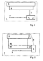
- Fig. 1 shows a functional cross-sectional view of a portable data carrier 1, which includes a processor 2 and an antenna 3 as contactless communication means.
- a light sensor 4 generates an enable signal 5, which indicates to the processor 2 that contactless communication may be performed.
- thermochromic layer 6 Towards the outside of the portable data carrier 1, there is a thermochromic layer 6 above the light sensor 4.
- the thermochromic layer 6 is intransparent in its ground state for light having a first wavelength.
- it can represent a first optical information perceptible to the user, for example the color "red", a stop sign or an icon for an opened switch.
- the user can change the light transmittance of the thermochromic layer 6 at least for the first frequency by manual heating of the thermochromic layer, in particular by placing a finger or by rubbing.
- the change of the light passing through the thermochromic layer 6 to the light sensor 4 is detected.
- the subsequently generated enable signal 5 notifies the processor 2 not only that light has been detected, but also that the user has deliberately operated a switch to allow contactless communication.
- the thermochromic layer 6 In the second, heated state, the thermochromic layer 6 also provides the user with altered optical information, such as the color green, an hourglass, or a closed switch symbol.
- the optical information thus indicates to the user a switching state of the thermochromic layer 6 (as a switch).
- it may be adapted to indicate to the user that and / or where he may release a communication of the portable data carrier 1 through interaction.
- thermochromic layer means for maintaining the release can be provided; However, this does not fall under the present invention.
- the maintaining means are in particular adapted to maintain the release irrespective of the presence of a communication field and / or for a suitable period of time.
- the appropriate period of time can be selected as the maximum expected communication duration, optionally plus an expected time until a communication field is present or the portable data carrier is led by the user into this field.
- Maintenance means may be provided in the contactless communication means, for example by storing the release as information and monitoring a timer (time counter). After the expiry of the timer, the release information is deleted, thus terminating the communication readiness. The timer may optionally be restarted by predetermined communication events. If a communication has been started before the expiration of the timer, the communication or corresponding transaction is also completed. The release is insofar a release for receiving a contactless communication.
- the switch can also serve as a maintenance means. If the switch is switchable between two permanent states (0 or 1), no further maintenance means are necessary.
- the thermochromic layer 6 can usually maintain its switching state only for too short a time, therefore additional maintenance means should be provided.
- a phosphorescent substance may be contained in the light sensor or at another suitable location. Suitable locations are, for example, a layer adjoining the light sensor or a transparent intermediate layer, not shown, which is arranged between the light sensor 4 and the thermochromic layer 6.
- the light sensor 4 may be configured as a photovoltaic element.
- This form of a sensor is not only inexpensive, but also easily integrated into the structure of the portable data carrier.
- the photovoltaic element makes it possible to provide maintenance means just to bridge the otherwise critical period of time in which there is still no communication field which also supplies the portable data carrier 1 with the energy necessary for operating the processor 2.
- the enable signal of the photovoltaic element can apply the energy necessary for the storage of the release information.
- a capacitor as a maintenance means is a simple element and also well adjustable in terms of temporal behavior. The capacitor is charged by the enable signal. A minimum charge state of the capacitor is evaluated by the processor 2 as stored, positive release information. The characteristics or arrangement of the capacitor are chosen so that it discharges to the minimum state of charge until the expiration of the appropriate period above.
- the light sensor 4 preferably detects the daylight and / or the artificial light of a room lighting.
- Fig. 2 shows, also as a functional cross-sectional view, another variant of a portable data carrier 1.
- the illustrated portable data carrier 1 includes a heating element 7, which via a supply line 8 is powered by the contactless communication means 2, 3 with energy.
- the light sensor comprises an optional transparent region 41, a light-conducting and / or collecting region 42 and the actual sensor as photosensitive element 43.
- the light-sensitive element 43 may be integrated in the processor 2.
- thermochromic layer is transmissive and the light is passed over the transparent region and light guide 42 to the photosensitive element 43, which then generates the enable signal.
- the heating element 7 can serve as a maintenance means. Via the optional connecting line 8, the heating element 7 receives energy, which is preferably taken from the communication field. It heats the thermochromic layer 6 and thus maintains the enable signal. Alternatively or additionally, the energy for the heating element 7 can also originate from an energy store, such as a battery, of the portable data carrier 1. If, as already described, the thermochromic layer also contains optical information for the user, it is thus also possible at the same time the optical information is maintained.
- the heating element is preferably arranged as a transparent intermediate layer between the thermochromic layer 6 and the light sensor.
- the antenna and the light sensor are arranged in the same plane, wherein the plane is parallel to the thermochromic layer.
- the antenna 3 can be provided, for example, together with the light sensor and optionally also the processor on a carrier substrate as an inlay for the production of the data carrier.
- the switch is repeatedly switchable.
- the following are in particular with reference to Fig. 3 Embodiments of the invention described in which the switch is irreversibly switchable.
- the user receives his portable data carrier and can release it for use by the irreversible switching process. This allows the user initial recognition.
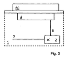
- Fig. 3 shows - as a non-inventive embodiment - a removably disposed on the outside of the portable data carrier 1 switching element 60.
- the switching element 60 is at least for a wavelength of daylight intransparent, for example, it is colored black or red.
- the further construction of the portable data carrier 1 with light sensor 4, enable signal 5, antenna 3 and processor 2 corresponds to the structure according to FIG. 1 ,
- the light sensor 4 is adapted to generate the enable signal when using the incoming light detects that the switching element 60 has been removed from the portable data carrier.
- the switching element 60 may be configured, for example, as a scratch-off or removable sticker.
- the irreversibly removable element or the portable data carrier should be equipped with a tamper detection protection, which makes a manipulation attempt by removing and re-attaching the user recognizable.
- the removable element (on its back side) or the portable data carrier may be provided with a light- and / or oxygen-sensitive element in the region on which the removable element is applied.
- the element Upon removal of the switching element 60, the element responds to the oxygen or light with an irreversible color change.
- the color changes only so fast that the user can perceive the change well. That the change should not be so slow that it does not attract the attention of the user or so fast that the user can not recognize it.
- thermochromic layer 6 could be adapted to allow a color change in response to heat only once.
- this layer could respond to pressure as user interaction with an irreversibly altered translucency.
- the change could be caused in the layer by a chemical reaction, for example by the mixing of two components after a breakup of microcapsules or by pressing two adjacent, corresponding sublayers.
Landscapes
- Engineering & Computer Science (AREA)
- Computer Hardware Design (AREA)
- Microelectronics & Electronic Packaging (AREA)
- Physics & Mathematics (AREA)
- General Physics & Mathematics (AREA)
- Theoretical Computer Science (AREA)
- Optical Communication System (AREA)
- Telephone Set Structure (AREA)
- Credit Cards Or The Like (AREA)
- Reduction Or Emphasis Of Bandwidth Of Signals (AREA)
Claims (11)
- Support de données portatif (1) comprenant
un moyen de communication sans contact (2, 3) pour réaliser une communication sans contact qui comprend une antenne (3) et un processeur (2) relié à l'antenne (3) ;
un capteur lumineux (4) qui détecte de la lumière entrante ;
dans lequel le support de données portatif (1) est installé pour effectuer une communication sans contact à l'aide du moyen de communication sans contact dépendamment de la lumière détectée lorsque de la lumière entrante est détectée ou pour ne pas l'effectuer lorsque aucune lumière entrante n'est détectée ; et
un élément de commutation (6) pouvant être actionné par un utilisateur du support de données portatif qui est réalisé de sorte que l'arrivée de lumière sur le capteur lumineux (4) dépend de l'état de commutation de l'élément de commutation (6),
caractérisé en ce que
l'élément de commutation (6) est disposé au sein du support de données portatif (1) et
l'élément de commutation (6) est réalisé en tant qu'élément pouvant être commuté de manière irréversible qui se modifie de manière irréversible dans sa perméabilité lumineuse après actionnement par l'utilisateur. - Support de données portatif (1) selon la revendication 1, caractérisé en ce que l'élément de commutation (6) est disposé entre le capteur lumineux et le côté externe du support de données portatif.
- Support de données portatif (1) selon l'une quelconque des revendications précédentes, caractérisé en ce que le capteur lumineux (4) est adapté à générer un signal de déblocage (5) pour débloquer la communication sans contact à l'aide du moyen de communication sans contact (2, 3).
- Support de données portatif (1) selon l'une quelconque des revendications précédentes, caractérisé par des moyens (2 ; 6 ; 41, 42 ; 7, 8) pour le maintien d'un déblocage de la communication sans contact.
- Support de données portatif (1) selon la revendication 4, caractérisé en ce que les moyens de maintien (2 ; 6 ; 41, 42 ; 7, 8) sont adaptés à maintenir le déblocage pendant une période prédéterminée.
- Support de données portatif (1) selon la revendication 4 ou 5, caractérisé en ce que la période prédéterminée est choisie en tant que durée de communication maximale à attendre, notamment majorée d'un temps à attendre jusqu'à présence d'un champ de communication.
- Support de données portatif (1) selon l'une quelconque des revendications 4 à 6, caractérisé en ce que les moyens de maintien sont contenus dans le capteur lumineux (6).
- Support de données portatif (1) selon l'une quelconque des revendications 4 à 7, caractérisé en ce que les moyens de maintien sont contenus dans le moyen de communication (2, 3).
- Support de données portatif (1) selon l'une quelconque des revendications précédentes, caractérisé en ce que le capteur lumineux comprend un élément conducteur de lumière (41) et un élément sensible à la lumière (42).
- Support de données portatif (1) selon l'une quelconque des revendications précédentes, caractérisé par des moyens d'affichage d'un état de déblocage pour l'utilisateur.
- Utilisation d'un support de données portatif (1) selon l'une quelconque des revendications précédentes, caractérisée en ce que l'utilisateur débloque pour l'utilisation le support de données portatif par le processus de commutation irréversible et il est ainsi permis à l'utilisateur une reconnaissance de première utilisation.
Applications Claiming Priority (2)
| Application Number | Priority Date | Filing Date | Title |
|---|---|---|---|
| DE102007009213A DE102007009213A1 (de) | 2007-02-26 | 2007-02-26 | Tragbarer Datenträger |
| EP08003257A EP1962232B1 (fr) | 2007-02-26 | 2008-02-22 | Support de données portatif |
Related Parent Applications (1)
| Application Number | Title | Priority Date | Filing Date |
|---|---|---|---|
| EP08003257.6 Division | 2008-02-22 |
Publications (3)
| Publication Number | Publication Date |
|---|---|
| EP2242006A2 EP2242006A2 (fr) | 2010-10-20 |
| EP2242006A3 EP2242006A3 (fr) | 2011-03-30 |
| EP2242006B1 true EP2242006B1 (fr) | 2013-06-26 |
Family
ID=39341769
Family Applications (2)
| Application Number | Title | Priority Date | Filing Date |
|---|---|---|---|
| EP08003257A Not-in-force EP1962232B1 (fr) | 2007-02-26 | 2008-02-22 | Support de données portatif |
| EP10007364.2A Not-in-force EP2242006B1 (fr) | 2007-02-26 | 2008-02-22 | Support de données portatif |
Family Applications Before (1)
| Application Number | Title | Priority Date | Filing Date |
|---|---|---|---|
| EP08003257A Not-in-force EP1962232B1 (fr) | 2007-02-26 | 2008-02-22 | Support de données portatif |
Country Status (3)
| Country | Link |
|---|---|
| EP (2) | EP1962232B1 (fr) |
| AT (1) | ATE494598T1 (fr) |
| DE (2) | DE102007009213A1 (fr) |
Families Citing this family (6)
| Publication number | Priority date | Publication date | Assignee | Title |
|---|---|---|---|---|
| US9135547B2 (en) * | 2008-12-19 | 2015-09-15 | Avery Dennison Corporation | Optical control of RFID chips |
| US8760295B2 (en) | 2008-12-19 | 2014-06-24 | Avery Dennison Corporation | Apparatus and methods for treating a wound |
| DE102009011821A1 (de) * | 2009-03-05 | 2010-09-09 | Giesecke & Devrient Gmbh | Tragbarer Datenträger |
| DE102010054054B4 (de) | 2010-12-10 | 2024-10-17 | Giesecke+Devrient ePayments GmbH | Datenträger mit Thermochromschicht zur Eingabebestätigung |
| US8730045B2 (en) | 2010-12-16 | 2014-05-20 | Avery Dennison Corporation | Isolating and RFID-based sensor from environmental interference |
| EP4498283A1 (fr) | 2023-07-24 | 2025-01-29 | HID Global CID SAS | Document d'identification avec fonction de sécurité activable |
Family Cites Families (15)
| Publication number | Priority date | Publication date | Assignee | Title |
|---|---|---|---|---|
| EP0715760B1 (fr) * | 1994-07-04 | 2001-03-21 | VALTAC, Alex Beaud | Etiquette electronique a lecture/ecriture optique |
| US5874724A (en) | 1997-01-10 | 1999-02-23 | International Business Machines Corporation | Light selectable radio frequency identification tag and method therefor |
| JP4212068B2 (ja) | 1997-05-19 | 2009-01-21 | ローム株式会社 | Icカードおよびicチップモジュール |
| JP3418322B2 (ja) * | 1997-08-28 | 2003-06-23 | 日本電信電話株式会社 | 使用状態表示機能付きicカードおよびicカードシステム |
| US6121544A (en) | 1998-01-15 | 2000-09-19 | Petsinger; Julie Ann | Electromagnetic shield to prevent surreptitious access to contactless smartcards |
| US6501390B1 (en) * | 1999-01-11 | 2002-12-31 | International Business Machines Corporation | Method and apparatus for securely determining aspects of the history of a good |
| US6830193B2 (en) * | 2001-11-29 | 2004-12-14 | Matsushita Electric Industrial Co., Ltd. | Non-contact IC card |
| DE20209132U1 (de) * | 2002-06-12 | 2002-10-02 | SimonsVoss Technologies AG, 85774 Unterföhring | Vorrichtung zum Sichern von passiven Systemen gegen manipulatives Ansprechen |
| US7002474B2 (en) | 2002-07-17 | 2006-02-21 | Ncr Corporation | Radio frequency identification (RFID) tag and a method of operating an RFID tag |
| US6863220B2 (en) | 2002-12-31 | 2005-03-08 | Massachusetts Institute Of Technology | Manually operated switch for enabling and disabling an RFID card |
| US20060005050A1 (en) | 2004-06-10 | 2006-01-05 | Supercom Ltd. | Tamper-free and forgery-proof passport and methods for providing same |
| US20060187060A1 (en) | 2005-02-07 | 2006-08-24 | Colby Steven M | Identity devices including radio frequency shielding |
| DE102005031448A1 (de) * | 2005-07-04 | 2007-01-11 | Polyic Gmbh & Co. Kg | Aktivierbare optische Schicht |
| AU2006203513A1 (en) * | 2005-08-15 | 2007-03-01 | Assa Abloy Ab | Photon Authenticated RFID Transponder |
| DE102007009215A1 (de) * | 2007-02-26 | 2008-09-18 | Giesecke & Devrient Gmbh | Tragbarer Datenträger |
-
2007
- 2007-02-26 DE DE102007009213A patent/DE102007009213A1/de not_active Withdrawn
-
2008
- 2008-02-22 DE DE502008002181T patent/DE502008002181D1/de active Active
- 2008-02-22 EP EP08003257A patent/EP1962232B1/fr not_active Not-in-force
- 2008-02-22 EP EP10007364.2A patent/EP2242006B1/fr not_active Not-in-force
- 2008-02-22 AT AT08003257T patent/ATE494598T1/de active
Also Published As
| Publication number | Publication date |
|---|---|
| DE502008002181D1 (de) | 2011-02-17 |
| EP1962232B1 (fr) | 2011-01-05 |
| ATE494598T1 (de) | 2011-01-15 |
| DE102007009213A1 (de) | 2008-08-28 |
| EP2242006A2 (fr) | 2010-10-20 |
| EP1962232A2 (fr) | 2008-08-27 |
| EP1962232A3 (fr) | 2009-09-30 |
| EP2242006A3 (fr) | 2011-03-30 |
Similar Documents
| Publication | Publication Date | Title |
|---|---|---|
| EP2242006B1 (fr) | Support de données portatif | |
| EP0327541B1 (fr) | Systeme de communication automatisee pour la transmission de donnees | |
| DE2560080C2 (de) | Datenaustauschanordnung | |
| WO1997022084A1 (fr) | Carte a puce | |
| WO2011042349A1 (fr) | Document | |
| AT507620B1 (de) | Mobiler datenspeicher | |
| DE2627981B2 (de) | Identifizierungssystem mittels Fingerabdrucken | |
| DE1574150A1 (de) | Kontrollgeraet zur Gewinnung von Aufzeichnungen | |
| DE60213767T2 (de) | Optisches identifizierungs-und markierungssystem | |
| DE102014117901B4 (de) | Bewegungserkennungseinheit und -System, Verfahren zum Betreiben einer Bewegungserkennungseinheit und entsprechendes Computerprogramm | |
| EP2722788A1 (fr) | Dispositif de lecture d'une carte à puce et procédé de détection d'un module de skimming | |
| EP2930699A1 (fr) | Caractéristique de sécurité comprenant une section de code et de marquage | |
| DE202019105456U1 (de) | Armband zum Test auf KO Tropfen | |
| EP2150943B1 (fr) | Procédé d'utilisation initiale d'une carte à puce | |
| WO2017025187A1 (fr) | Support de données portable, en particulier carte à puce | |
| EP2455925B1 (fr) | Procédé et dispositif de défense contre les tentatives de manipulation sur un système de caméra | |
| EP1986167A1 (fr) | Caractéristique modulaire pour surfaces de systèmes auto-commandés | |
| WO2021144035A1 (fr) | Procédé de sortie d'un état d'au moins un sceau, sceau et système | |
| EP3531357A1 (fr) | Système de caisse, procédé d'authentification sur un système de caisse, programme informatique ainsi que support lisible par ordinateur | |
| EP1917615B1 (fr) | Procede pour mettre en oeuvre des processus d'application | |
| DE3615207A1 (de) | Personenidentifikationssystem | |
| DE102004011960A1 (de) | Tragbarer Datenträger mit biometrischem Sensor und Verfahren zur Authentisierung ihres Benutzers | |
| DE202009001666U1 (de) | Anordnung zum Erfassen und Verarbeiten von Daten an Kassen | |
| CN208386767U (zh) | 一种高清视频叠加处理系统 | |
| DE102019130049A1 (de) | Kartenetui |
Legal Events
| Date | Code | Title | Description |
|---|---|---|---|
| PUAI | Public reference made under article 153(3) epc to a published international application that has entered the european phase |
Free format text: ORIGINAL CODE: 0009012 |
|
| AC | Divisional application: reference to earlier application |
Ref document number: 1962232 Country of ref document: EP Kind code of ref document: P |
|
| AK | Designated contracting states |
Kind code of ref document: A2 Designated state(s): AT BE BG CH CY CZ DE DK EE ES FI FR GB GR HR HU IE IS IT LI LT LU LV MC MT NL NO PL PT RO SE SI SK TR |
|
| PUAL | Search report despatched |
Free format text: ORIGINAL CODE: 0009013 |
|
| AK | Designated contracting states |
Kind code of ref document: A3 Designated state(s): AT BE BG CH CY CZ DE DK EE ES FI FR GB GR HR HU IE IS IT LI LT LU LV MC MT NL NO PL PT RO SE SI SK TR |
|
| 17P | Request for examination filed |
Effective date: 20110930 |
|
| 17Q | First examination report despatched |
Effective date: 20111128 |
|
| GRAP | Despatch of communication of intention to grant a patent |
Free format text: ORIGINAL CODE: EPIDOSNIGR1 |
|
| GRAS | Grant fee paid |
Free format text: ORIGINAL CODE: EPIDOSNIGR3 |
|
| GRAA | (expected) grant |
Free format text: ORIGINAL CODE: 0009210 |
|
| AC | Divisional application: reference to earlier application |
Ref document number: 1962232 Country of ref document: EP Kind code of ref document: P |
|
| AK | Designated contracting states |
Kind code of ref document: B1 Designated state(s): AT BE BG CH CY CZ DE DK EE ES FI FR GB GR HR HU IE IS IT LI LT LU LV MC MT NL NO PL PT RO SE SI SK TR |
|
| REG | Reference to a national code |
Ref country code: GB Ref legal event code: FG4D Free format text: NOT ENGLISH |
|
| REG | Reference to a national code |
Ref country code: CH Ref legal event code: EP |
|
| REG | Reference to a national code |
Ref country code: AT Ref legal event code: REF Ref document number: 618985 Country of ref document: AT Kind code of ref document: T Effective date: 20130715 |
|
| REG | Reference to a national code |
Ref country code: IE Ref legal event code: FG4D Free format text: LANGUAGE OF EP DOCUMENT: GERMAN |
|
| REG | Reference to a national code |
Ref country code: DE Ref legal event code: R096 Ref document number: 502008010205 Country of ref document: DE Effective date: 20130822 |
|
| PG25 | Lapsed in a contracting state [announced via postgrant information from national office to epo] |
Ref country code: SE Free format text: LAPSE BECAUSE OF FAILURE TO SUBMIT A TRANSLATION OF THE DESCRIPTION OR TO PAY THE FEE WITHIN THE PRESCRIBED TIME-LIMIT Effective date: 20130626 Ref country code: SI Free format text: LAPSE BECAUSE OF FAILURE TO SUBMIT A TRANSLATION OF THE DESCRIPTION OR TO PAY THE FEE WITHIN THE PRESCRIBED TIME-LIMIT Effective date: 20130626 Ref country code: NO Free format text: LAPSE BECAUSE OF FAILURE TO SUBMIT A TRANSLATION OF THE DESCRIPTION OR TO PAY THE FEE WITHIN THE PRESCRIBED TIME-LIMIT Effective date: 20130926 Ref country code: FI Free format text: LAPSE BECAUSE OF FAILURE TO SUBMIT A TRANSLATION OF THE DESCRIPTION OR TO PAY THE FEE WITHIN THE PRESCRIBED TIME-LIMIT Effective date: 20130626 Ref country code: GR Free format text: LAPSE BECAUSE OF FAILURE TO SUBMIT A TRANSLATION OF THE DESCRIPTION OR TO PAY THE FEE WITHIN THE PRESCRIBED TIME-LIMIT Effective date: 20130927 Ref country code: LT Free format text: LAPSE BECAUSE OF FAILURE TO SUBMIT A TRANSLATION OF THE DESCRIPTION OR TO PAY THE FEE WITHIN THE PRESCRIBED TIME-LIMIT Effective date: 20130626 |
|
| REG | Reference to a national code |
Ref country code: LT Ref legal event code: MG4D |
|
| PG25 | Lapsed in a contracting state [announced via postgrant information from national office to epo] |
Ref country code: HR Free format text: LAPSE BECAUSE OF FAILURE TO SUBMIT A TRANSLATION OF THE DESCRIPTION OR TO PAY THE FEE WITHIN THE PRESCRIBED TIME-LIMIT Effective date: 20130626 Ref country code: BG Free format text: LAPSE BECAUSE OF FAILURE TO SUBMIT A TRANSLATION OF THE DESCRIPTION OR TO PAY THE FEE WITHIN THE PRESCRIBED TIME-LIMIT Effective date: 20130926 |
|
| REG | Reference to a national code |
Ref country code: NL Ref legal event code: VDEP Effective date: 20130626 |
|
| PG25 | Lapsed in a contracting state [announced via postgrant information from national office to epo] |
Ref country code: LV Free format text: LAPSE BECAUSE OF FAILURE TO SUBMIT A TRANSLATION OF THE DESCRIPTION OR TO PAY THE FEE WITHIN THE PRESCRIBED TIME-LIMIT Effective date: 20130626 |
|
| PG25 | Lapsed in a contracting state [announced via postgrant information from national office to epo] |
Ref country code: PT Free format text: LAPSE BECAUSE OF FAILURE TO SUBMIT A TRANSLATION OF THE DESCRIPTION OR TO PAY THE FEE WITHIN THE PRESCRIBED TIME-LIMIT Effective date: 20131028 Ref country code: CY Free format text: LAPSE BECAUSE OF FAILURE TO SUBMIT A TRANSLATION OF THE DESCRIPTION OR TO PAY THE FEE WITHIN THE PRESCRIBED TIME-LIMIT Effective date: 20130710 Ref country code: IS Free format text: LAPSE BECAUSE OF FAILURE TO SUBMIT A TRANSLATION OF THE DESCRIPTION OR TO PAY THE FEE WITHIN THE PRESCRIBED TIME-LIMIT Effective date: 20131026 Ref country code: SK Free format text: LAPSE BECAUSE OF FAILURE TO SUBMIT A TRANSLATION OF THE DESCRIPTION OR TO PAY THE FEE WITHIN THE PRESCRIBED TIME-LIMIT Effective date: 20130626 Ref country code: CZ Free format text: LAPSE BECAUSE OF FAILURE TO SUBMIT A TRANSLATION OF THE DESCRIPTION OR TO PAY THE FEE WITHIN THE PRESCRIBED TIME-LIMIT Effective date: 20130626 Ref country code: EE Free format text: LAPSE BECAUSE OF FAILURE TO SUBMIT A TRANSLATION OF THE DESCRIPTION OR TO PAY THE FEE WITHIN THE PRESCRIBED TIME-LIMIT Effective date: 20130626 |
|
| PG25 | Lapsed in a contracting state [announced via postgrant information from national office to epo] |
Ref country code: ES Free format text: LAPSE BECAUSE OF FAILURE TO SUBMIT A TRANSLATION OF THE DESCRIPTION OR TO PAY THE FEE WITHIN THE PRESCRIBED TIME-LIMIT Effective date: 20131007 Ref country code: NL Free format text: LAPSE BECAUSE OF FAILURE TO SUBMIT A TRANSLATION OF THE DESCRIPTION OR TO PAY THE FEE WITHIN THE PRESCRIBED TIME-LIMIT Effective date: 20130626 Ref country code: PL Free format text: LAPSE BECAUSE OF FAILURE TO SUBMIT A TRANSLATION OF THE DESCRIPTION OR TO PAY THE FEE WITHIN THE PRESCRIBED TIME-LIMIT Effective date: 20130626 Ref country code: RO Free format text: LAPSE BECAUSE OF FAILURE TO SUBMIT A TRANSLATION OF THE DESCRIPTION OR TO PAY THE FEE WITHIN THE PRESCRIBED TIME-LIMIT Effective date: 20130626 |
|
| PG25 | Lapsed in a contracting state [announced via postgrant information from national office to epo] |
Ref country code: CY Free format text: LAPSE BECAUSE OF FAILURE TO SUBMIT A TRANSLATION OF THE DESCRIPTION OR TO PAY THE FEE WITHIN THE PRESCRIBED TIME-LIMIT Effective date: 20130626 |
|
| PG25 | Lapsed in a contracting state [announced via postgrant information from national office to epo] |
Ref country code: DK Free format text: LAPSE BECAUSE OF FAILURE TO SUBMIT A TRANSLATION OF THE DESCRIPTION OR TO PAY THE FEE WITHIN THE PRESCRIBED TIME-LIMIT Effective date: 20130626 |
|
| PLBE | No opposition filed within time limit |
Free format text: ORIGINAL CODE: 0009261 |
|
| STAA | Information on the status of an ep patent application or granted ep patent |
Free format text: STATUS: NO OPPOSITION FILED WITHIN TIME LIMIT |
|
| PG25 | Lapsed in a contracting state [announced via postgrant information from national office to epo] |
Ref country code: IT Free format text: LAPSE BECAUSE OF FAILURE TO SUBMIT A TRANSLATION OF THE DESCRIPTION OR TO PAY THE FEE WITHIN THE PRESCRIBED TIME-LIMIT Effective date: 20130626 |
|
| 26N | No opposition filed |
Effective date: 20140327 |
|
| REG | Reference to a national code |
Ref country code: DE Ref legal event code: R097 Ref document number: 502008010205 Country of ref document: DE Effective date: 20140327 |
|
| BERE | Be: lapsed |
Owner name: GIESECKE & DEVRIENT G.M.B.H. Effective date: 20140228 |
|
| PG25 | Lapsed in a contracting state [announced via postgrant information from national office to epo] |
Ref country code: MC Free format text: LAPSE BECAUSE OF FAILURE TO SUBMIT A TRANSLATION OF THE DESCRIPTION OR TO PAY THE FEE WITHIN THE PRESCRIBED TIME-LIMIT Effective date: 20130626 Ref country code: LU Free format text: LAPSE BECAUSE OF FAILURE TO SUBMIT A TRANSLATION OF THE DESCRIPTION OR TO PAY THE FEE WITHIN THE PRESCRIBED TIME-LIMIT Effective date: 20140222 |
|
| REG | Reference to a national code |
Ref country code: CH Ref legal event code: PL |
|
| PG25 | Lapsed in a contracting state [announced via postgrant information from national office to epo] |
Ref country code: LI Free format text: LAPSE BECAUSE OF NON-PAYMENT OF DUE FEES Effective date: 20140228 Ref country code: CH Free format text: LAPSE BECAUSE OF NON-PAYMENT OF DUE FEES Effective date: 20140228 |
|
| REG | Reference to a national code |
Ref country code: IE Ref legal event code: MM4A |
|
| PG25 | Lapsed in a contracting state [announced via postgrant information from national office to epo] |
Ref country code: BE Free format text: LAPSE BECAUSE OF NON-PAYMENT OF DUE FEES Effective date: 20140228 Ref country code: IE Free format text: LAPSE BECAUSE OF NON-PAYMENT OF DUE FEES Effective date: 20140222 |
|
| REG | Reference to a national code |
Ref country code: AT Ref legal event code: MM01 Ref document number: 618985 Country of ref document: AT Kind code of ref document: T Effective date: 20140222 |
|
| PG25 | Lapsed in a contracting state [announced via postgrant information from national office to epo] |
Ref country code: AT Free format text: LAPSE BECAUSE OF NON-PAYMENT OF DUE FEES Effective date: 20140222 |
|
| REG | Reference to a national code |
Ref country code: FR Ref legal event code: PLFP Year of fee payment: 9 |
|
| PG25 | Lapsed in a contracting state [announced via postgrant information from national office to epo] |
Ref country code: MT Free format text: LAPSE BECAUSE OF FAILURE TO SUBMIT A TRANSLATION OF THE DESCRIPTION OR TO PAY THE FEE WITHIN THE PRESCRIBED TIME-LIMIT Effective date: 20130626 |
|
| PG25 | Lapsed in a contracting state [announced via postgrant information from national office to epo] |
Ref country code: TR Free format text: LAPSE BECAUSE OF FAILURE TO SUBMIT A TRANSLATION OF THE DESCRIPTION OR TO PAY THE FEE WITHIN THE PRESCRIBED TIME-LIMIT Effective date: 20130626 Ref country code: HU Free format text: LAPSE BECAUSE OF FAILURE TO SUBMIT A TRANSLATION OF THE DESCRIPTION OR TO PAY THE FEE WITHIN THE PRESCRIBED TIME-LIMIT; INVALID AB INITIO Effective date: 20080222 |
|
| REG | Reference to a national code |
Ref country code: FR Ref legal event code: PLFP Year of fee payment: 10 |
|
| PGFP | Annual fee paid to national office [announced via postgrant information from national office to epo] |
Ref country code: DE Payment date: 20170228 Year of fee payment: 10 Ref country code: FR Payment date: 20170220 Year of fee payment: 10 |
|
| PGFP | Annual fee paid to national office [announced via postgrant information from national office to epo] |
Ref country code: GB Payment date: 20170221 Year of fee payment: 10 |
|
| REG | Reference to a national code |
Ref country code: DE Ref legal event code: R081 Ref document number: 502008010205 Country of ref document: DE Owner name: GIESECKE+DEVRIENT MOBILE SECURITY GMBH, DE Free format text: FORMER OWNER: GIESECKE & DEVRIENT GMBH, 81677 MUENCHEN, DE |
|
| REG | Reference to a national code |
Ref country code: GB Ref legal event code: 732E Free format text: REGISTERED BETWEEN 20180118 AND 20180124 |
|
| REG | Reference to a national code |
Ref country code: FR Ref legal event code: TP Owner name: GIESECKE+DEVRIENT MOBILE SECURITY GMBH, DE Effective date: 20180619 |
|
| REG | Reference to a national code |
Ref country code: DE Ref legal event code: R119 Ref document number: 502008010205 Country of ref document: DE |
|
| GBPC | Gb: european patent ceased through non-payment of renewal fee |
Effective date: 20180222 |
|
| REG | Reference to a national code |
Ref country code: FR Ref legal event code: ST Effective date: 20181031 |
|
| PG25 | Lapsed in a contracting state [announced via postgrant information from national office to epo] |
Ref country code: DE Free format text: LAPSE BECAUSE OF NON-PAYMENT OF DUE FEES Effective date: 20180901 |
|
| PG25 | Lapsed in a contracting state [announced via postgrant information from national office to epo] |
Ref country code: GB Free format text: LAPSE BECAUSE OF NON-PAYMENT OF DUE FEES Effective date: 20180222 Ref country code: FR Free format text: LAPSE BECAUSE OF NON-PAYMENT OF DUE FEES Effective date: 20180228 |