EP2241759B1 - Halb eingetauchte, vertikale Vorrichtung zum Bewegen einer Flüssigkeit - Google Patents
Halb eingetauchte, vertikale Vorrichtung zum Bewegen einer Flüssigkeit Download PDFInfo
- Publication number
- EP2241759B1 EP2241759B1 EP10159200A EP10159200A EP2241759B1 EP 2241759 B1 EP2241759 B1 EP 2241759B1 EP 10159200 A EP10159200 A EP 10159200A EP 10159200 A EP10159200 A EP 10159200A EP 2241759 B1 EP2241759 B1 EP 2241759B1
- Authority
- EP
- European Patent Office
- Prior art keywords
- motor assembly
- ventilation unit
- cooling
- liquid
- air
- Prior art date
- Legal status (The legal status is an assumption and is not a legal conclusion. Google has not performed a legal analysis and makes no representation as to the accuracy of the status listed.)
- Active
Links
Images


Classifications
-
- H—ELECTRICITY
- H02—GENERATION; CONVERSION OR DISTRIBUTION OF ELECTRIC POWER
- H02K—DYNAMO-ELECTRIC MACHINES
- H02K7/00—Arrangements for handling mechanical energy structurally associated with dynamo-electric machines, e.g. structural association with mechanical driving motors or auxiliary dynamo-electric machines
- H02K7/14—Structural association with mechanical loads, e.g. with hand-held machine tools or fans
-
- B—PERFORMING OPERATIONS; TRANSPORTING
- B01—PHYSICAL OR CHEMICAL PROCESSES OR APPARATUS IN GENERAL
- B01F—MIXING, e.g. DISSOLVING, EMULSIFYING OR DISPERSING
- B01F27/00—Mixers with rotary stirring devices in fixed receptacles; Kneaders
- B01F27/80—Mixers with rotary stirring devices in fixed receptacles; Kneaders with stirrers rotating about a substantially vertical axis
- B01F27/91—Mixers with rotary stirring devices in fixed receptacles; Kneaders with stirrers rotating about a substantially vertical axis with propellers
-
- H—ELECTRICITY
- H02—GENERATION; CONVERSION OR DISTRIBUTION OF ELECTRIC POWER
- H02K—DYNAMO-ELECTRIC MACHINES
- H02K5/00—Casings; Enclosures; Supports
- H02K5/04—Casings or enclosures characterised by the shape, form or construction thereof
- H02K5/18—Casings or enclosures characterised by the shape, form or construction thereof with ribs or fins for improving heat transfer
-
- H—ELECTRICITY
- H02—GENERATION; CONVERSION OR DISTRIBUTION OF ELECTRIC POWER
- H02K—DYNAMO-ELECTRIC MACHINES
- H02K9/00—Arrangements for cooling or ventilating
- H02K9/02—Arrangements for cooling or ventilating by ambient air flowing through the machine
- H02K9/04—Arrangements for cooling or ventilating by ambient air flowing through the machine having means for generating a flow of cooling medium
- H02K9/06—Arrangements for cooling or ventilating by ambient air flowing through the machine having means for generating a flow of cooling medium with fans or impellers driven by the machine shaft
Definitions
- the present invention concerns a device for moving a liquid, of the type with a semi-submerged vertical drive axis, which can be used to move a cooling liquid, for example to transport the liquid from a containing tank to the final point of use, particularly, but not only, in refrigerators for catering, for example for tapping drinks such as beer, for domestic use or for the food industry, or in machine tools, or again for stirring the liquid in the containing tank.
- a pumping device to transport a cooling liquid through a delivery circuit from a suitable containing tank toward a user machine to be cooled, for example a machine tool.
- the level of the liquid diminishes and makes it necessary to fill up the liquid inside the tank.
- the cooling can also take place during the passage in the delivery circuit, for example in the application to refrigerators used in the public catering sector for the tapping of drinks. In the latter case, there is also a second circuit, called the return circuit, to recover the liquid.
- the pumping device which is used in the state of the art is of the type with a vertical drive axis, semi-submerged in the liquid, and is installed on an upper wall of the containing tank.
- the known pumping device is usually provided with a motor assembly, a ventilation unit and a hydraulic pumping member, supported by a support element, called shank, provided on the lower side of the motor assembly.
- the known pumping device is installed above the containing tank so that the ventilation unit and the motor assembly are not normally in contact with the liquid below, while the shank is partially immersed and the hydraulic pumping member is completely immersed in the cooling liquid.
- the motor assembly comprises an electric motor assembled on a structure which supports it. This support also acts as at least partial protection for the motor and as an electric protection.
- the motor assembly comprises an internal cylinder, called rotor, in which, along a common axis of alignment, a drive shaft is inserted in order to drive in rotation the hydraulic pumping members. The free rotation of the drive shaft is guaranteed by two bearings, upper and lower, positioned on opposite sides of the rotor, or equivalent components such as bushings or brasses.
- the ventilation unit able to cool the motor, is traditionally assembled on the upper side of the motor assembly and comprises a cooling fan attached on one end of the drive shaft.
- the fan pushes and conveys the air taken from the environment toward the motor assembly, cooling it.
- the hydraulic pumping member normally has one or more hydraulic chambers in which, generally, a hydraulic rotor or turbine is mounted, driven by the drive shaft.
- the motor assembly generates a rotational movement which is transferred to the drive shaft and then to the hydraulic pumping member, for the rotation of the rotor, which puts the liquid under pressure which is pushed toward one or more exit or delivery pipes, connected to the delivery circuit.
- the same rotational movement is also transferred to the cooling fan, which pushes the air toward the motor assembly, to cool it.
- the liquid contained in the tank is maintained at a minimum safety distance of about 10 mm - 20 mm from the lower side of the motor assembly, so that the same liquid, rising along the drive shaft, does not damage the elements which make up the motor assembly when the liquid is topped up, for example in the case of machine tools.
- topping-up is less frequent.
- the refrigerator produces a layer of ice in the containing tank, which increases the volume of liquid and consequently its level.
- a known pumping device is described for example in the document US-A-6,059,535 .
- This known pumping device includes an electric motor and is used to maintain the level of a liquid in a tank.
- a known motor assembly is described in the document US-A-4,670,677 .
- This motor assembly comprises a shell, open at the lower part, inside which a stator/rotor unit which drives a shaft is housed.
- the motor assembly comprises a cooling fan disposed on the front side of the shaft, with respect to the stator/rotor unit.
- This known motor assembly has the disadvantage that, being completely open in correspondence with the fan so as to allow the passage of cooling air taken in by the fan itself, which directly strikes the stator/rotor unit, it is not protected from possible infiltrations of water, flooding of the inside of the shell, the bearings and other sensitive components, as well as the entrance of humidity, dust, dirt or other, being thus exposed to risks of forced and premature dysfunctions and replacements.
- Purpose of the present invention is to achieve a device for moving liquid, of the semi-submerged vertical type, which is protected from flooding of the internal members of the motor assembly, thus prolonging the operating life, even in the event of excessive or unforeseen rise of the level of the cooling liquid and being able to operate in safety even in these difficult situations.
- the Applicant has devised, tested and embodied the present invention to overcome the shortcomings of the state of the art and to obtain these and other purposes and advantages.
- a device for moving a liquid can be used in association with a tank for containing the cooling liquid in a refrigeration unit, for example but not exclusively, in a machine tool, or in a plant for tapping drinks, and is typically located vertical, semi-submerged in the liquid.
- the movement device comprises:
- the motor assembly, the ventilation unit and the movement means of the liquid are disposed along a common axis, an axis disposed vertical during normal use.
- the ventilation unit is disposed, along the common axis, between the motor assembly and the movement means of the liquid, so as to distance, during normal use, the motor assembly from the liquid below, while still maintaining the same bulk of the traditional solutions known in the state of the art.
- the device according to the invention can operate in safety even in these difficult situations where the level of the liquid rises.
- the motor assembly can be an electric motor with low consumption, for example a brushless motor, an inverter motor or other.
- the motor assembly comprises a containing structure, disposed close to the ventilation unit, and a motor body.
- the containing structure is of the closed type and has a housing compartment internally in which the motor body is located, which is substantially isolated with respect to the outside. In this way the motor body, being isolated from the outside, is protected from the accidental entrance of water, humidity, dust, dirt or other.
- the containing structure has one or more passage ways, outside the housing compartment, which are in communication on one side with the ventilation unit and on the other side with the outside of the containing structure.
- the cooling air coming from the ventilation unit passes through the one or more passage ways, along a route which takes the air to lap the outside surface of the containing structure.
- the one or more passage ways are conformed to direct the cooling air at least along the outside surface of the containing structure, or inside ventilation channels provided along the outside surface, as shown hereafter in the description, so as to cool the motor assembly.
- the containing structure has externally heat exchange means suitable to exchange heat with the cooling air arriving, through the one or more passage ways, from the ventilation unit, in order to cool the motor body indirectly.
- the heat exchange means are configured as a surface with radial cooling fins, which completely or partly surrounds at least the lateral surface of the containing structure, preferably itself constituting said lateral surface, separating the internal housing compartment of the motor body from the outside.
- the present invention in any case guarantees an efficient cooling of the motor body, which occurs indirectly by means of heat exchange with the heat exchange means
- the heat exchange means are formed by one or more external ventilation channels, or chambers, made on the external surface of the containing structure of the motor.
- the external channels are defined by a closed cross section, which develops longitudinally from the lower part to the upper part of the containing structure, being open at the lower part and at the upper part for the passage of the cooling air.
- the cooling air is conveyed from the bottom upward, passing through the internal surface of the channels, in any case always outside the housing compartment of the motor body.
- the containing structure has at the upper part deflector means able to deflect the cooling air arriving from the ventilation unit toward an upper side of the containing structure where the motor body is contained. This allows to cool, at least partly, the upper portion of the motor assembly too.
- the ventilation unit is directly connected to the motor assembly, on a lower surface of the containing structure which houses the motor body of the motor assembly.
- the upper zone of the motor assembly can be used for supporting other objects, or for assembly close to or in contact with a wall, thus covering the upper zone, without for this reason obstructing or blocking the ventilation, as can happen in known solutions with upper ventilation, since the ventilation, in the present invention, occurs from the lower part of the motor assembly toward the upper part.
- the pumping device comprises a support structure able to support the movement means, which is connected on one side to the movement means and on the other side to the ventilation unit.
- the movement means comprise a hydraulic pumping member.
- the device according to the present invention is used to pump the liquid from the containing tank to a cooling circuit.
- the support structure can, in accordance with one form of embodiment, assume the shape of an oblong support element, commonly called shank, which supports the hydraulic pumping member from below.
- movement we mean the pumping of the liquid, that is, the transport of the liquid from the tank through the cooling circuit and toward the user machine to be refrigerated.
- the movement means comprises a stirrer element, of the screw or blade type for example, which has the function of keeping the refrigeration liquid stirred in the containing tank, advantageously to reduce the formation of layers of ice at the edges of the tank, thanks to the erosion of the ice by the liquid which is stirred.
- movement means comprise both the hydraulic pumping member and the stirrer element, advantageously integrated and aligned on the same axis and in this case the term "movement" includes both the meanings.
- the ventilation unit of the movement device is assembled, on the lower side of the motor assembly, above the movement means of the liquid so as to distance, during normal use, the motor assembly from the level of liquid in the refrigeration compartment containing the liquid.
- a variant of the present invention provides that the movement device, whether it is intended for pumping, stirring or both, is mounted directly above an upper wall of the containing tank, inserted in a suitable aperture through the upper wall itself.
- the ventilation unit is disposed above the upper wall of the container, externally to the refrigeration compartment.
- the movement device according to the invention is mounted above an upper wall, inserted in a suitable aperture, of the body of the machine tool, or refrigeration plant, to which the refrigeration unit is associated.
- movement device according to the invention is mounted suspended, below the upper wall of the body of the machine tool or refrigeration plant, for example by using attachment means associated with the upper part of the motor assembly, such as screw elements.
- the ventilation unit is provided with attachment means, for example flange type, so it can be mounted.
- the flange extends laterally from the body of the ventilation unit and is shaped so as to be associated and attached to a supporting plane, such as the wall of the tank or the machine tool or refrigeration plant.
- the movement device comprises a support structure to support the movement means, which is connected on one side to the movement means and on the other side to the ventilation unit.
- the support structure in the case where a hydraulic pumping member is used, is a single piece formed by an oblong element, inside which the drive shaft is housed to drive the hydraulic member, and by the body of the hydraulic pumping member itself, for example obtained by injection molding of a plastic material.
- the support structure is made in a single body with the ventilation unit and with the hydraulic pumping member. In some forms of embodiment, the support structure is a single piece formed by the oblong element and by the containing body of the ventilation unit.
- the support structure is a single piece formed by the oblong element, by the body of the hydraulic pumping member and also by the containing body of the ventilation unit.
- a further variant provides that the support structure is made as a separate piece both from the body of the hydraulic pumping member and also from the containing body of the ventilation unit, which are subsequently assembled and attached.
- the ventilation unit has an extension in height, particularly with respect to the lying plane of the upper wall, such as to define a safety distance between the maximum level that the liquid can reach in the containing tank and the position of the super-elevated motor assembly, which is thanks to the distancing function the interposed ventilation unit.
- the ventilation unit comprises a containing element, such as a cup or a cap, inside which an aeration seating is made in which a cooling fan is housed; the containing element is above the containing tank, outside the relative refrigeration compartment.
- the ventilation unit or the containing element thereof, has an upper aperture by means of which the cooling fan is facing toward the motor assembly, so as to direct the cooling air toward it.
- the ventilation unit moreover, also has a lower wall, suitably holed, to take in the cooled air.
- the lower wall of the ventilation unit faces toward the containing tank.
- the lower wall can rest on a supporting wall or plane of the containing tank or of the machine or implant to which the movement device in question is associated.
- connection element for example annular or other geometry, extends from the lower wall so as to connect to the support structure, to define a determinate region of coupling.
- the containing element, or cup is shaped so as to convey the air taken in from below toward the motor assembly.
- the ventilation unit is made as a single piece, for example obtained by means of injection molding of a suitable plastic material.
- the single piece is formed by a fan shaped so as to define a peripheral cup profile, or conveyance compartment, to direct the air taken in toward the motor assembly.
- the device for moving a liquid according to the present invention has a plurality of air holes made on the lower wall of the ventilation unit, directly facing toward the refrigeration compartment, through which the cooling fan takes in the air to cool the motor body.
- the fan can take in a stream of cold air from the refrigeration compartment, which is normally at a lower temperature than the external environment, thus improving the efficiency of cooling the motor body.
- the air holes comprise first holes made inside the connection element between the ventilation unit and support structure, and second holes disposed outside the coupling region between the connection element and the oblong element.
- the device according to the present invention can also be provided with third air holes made on the lateral surface of the connection element.
- the third holes perform an advantageous security function, allowing to always have a ventilation air intake for the fan, even in the case where there is a rise in the level in the support structure and flooding.
- a device 10 for moving a liquid, with a vertical drive axis, according to the present invention is shown in the form of embodiment of a device for pumping a cooling liquid 11.
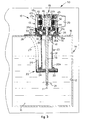
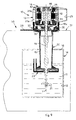
- the device 10 is shown installed on a containing tank 14 having a refrigeration compartment 12 containing cooling water 11, or other cooling liquid (for example glycol water, water-oil emulsion or other), for a refrigeration unit 50 ( fig. 3 ), shown only schematically in the drawings, of a refrigerator used in a tapping plant for drinks, for example for tapping beer in bars.
- a refrigeration unit 50 for example glycol water, water-oil emulsion or other
- the device 10 is attached, along a vertical axis Y ( fig. 3 ), on a support plane defined by a horizontal upper wall 16 of the containing tank 14, by means of a suitable flange 28 ( fig. 2 ).
- the upper wall 16 has an aperture 15 for the passage of part of the device 10, in order to partly emerge it in the water 11, as explained hereafter in the description.
- the device 10 comprises a motor assembly 18 having a motor body 25 inserted in the housing compartment 13a defined by a containing structure, or shell 13 ( figs. 4 and 4a ).
- the containing structure or shell 13, normally made of aluminum, is completely closed at the top, at the bottom and at the sides, so as to close in and completely surround the motor body 25 inside it, thus protecting it from the entrance of water, humidity, dust, dirt or other.
- This containing structure or shell 13 is formed by a lower side or wall 18a, an upper side or wall 18b and by a lateral surface with cooling fins 25a, thus delimiting the housing compartment 13a which surrounds the motor body 25.
- the lower side or wall 18a, the upper side or wall 18b and the lateral surface with cooling fins 25a are constrained to each other by means of male/female coupling and tie rods with screws or other equivalent attachment means.
- the advantage of the embodiment in aluminum, or other metal which allows good heat exchange, is that it increases the effectiveness of the cooling by means of the cooling fins 25a.
- aluminum is advantageous in that, as well as allowing a good heat exchange, it is known to be a material which is resistant to corrosion.
- the device 10 also comprises a ventilation unit 33, mounted on the lower side 18a ( fig. 3 ) of the containing structure or shell 13 which houses the motor body 25 of the motor assembly 18, an oblong element or shank 20, cylindrical in shape, or other suitable shape, with an internal cavity 31; the shank 20 extends downward from the ventilation unit 33 along the vertical axis Y, and a hydraulic pumping member 23, drivable by the motor assembly 18 to pump the cooling water 11 ( fig. 3 ).
- a ventilation unit 33 mounted on the lower side 18a ( fig. 3 ) of the containing structure or shell 13 which houses the motor body 25 of the motor assembly 18, an oblong element or shank 20, cylindrical in shape, or other suitable shape, with an internal cavity 31; the shank 20 extends downward from the ventilation unit 33 along the vertical axis Y, and a hydraulic pumping member 23, drivable by the motor assembly 18 to pump the cooling water 11 ( fig. 3 ).
- the hydraulic pumping member 23 is supported at a lower end 20a of the shank 20.
- the shank 20 is semi-submerged in the water 11, passing through the aperture 15 of the upper wall 16, as can be seen in fig. 3 , while the hydraulic pumping member 23 is completely submerged.
- a technical compartment 29 ( fig. 3 ) can be provided laterally, to house electronic or electromechanical components to command and control the device 10.
- the motor body 25 inserted in the housing compartment 13a comprises, in traditional fashion, a rotor 25b, electric coils 40, a stator 42, disposed along the vertical axis Y, in which a drive shaft 19 is inserted, able to rotate around the vertical axis Y.
- the free rotation of the drive shaft 19 is allowed by bearings, in this case two in number, lower 44 and upper 46, positioned on opposite sides of the rotor 25b of the motor assembly 18.
- the drive shaft 19 extends from the motor body 25, in this case downward, passing through an aperture 25c made in the lower side 18a of the containing structure or shell 13, in which the hydraulic seal is guaranteed by the lower bearing 44, watertight or normal, and possibly, if necessary, by additional sealing casings.
- the drive shaft 19 extends through the internal cavity 31 of the shank 20, to be coupled with the hydraulic pumping member 23, in particular with the relative hydraulic rotor or turbine 24.
- the ventilation unit 33 comprises a containing element 35 shaped like a cup, directly coupled with the lower side of the motor assembly 18, which has inside it an aeration seating or chamber 32 in which a cooling fan 30 is housed ( fig. 3 ).
- the containing element 35 has a suitable central aperture 37 for the passage of the drive shaft 19 ( fig. 3 ).
- the cooling fan 30 is thus directly attached to the drive shaft 19 and made to rotate thereby, thus cooling the motor assembly 18.
- the containing element 35 has a cylindrical lateral wall 35c, or other suitable shape, also quadrangular according to necessity ( fig. 3 ), an upper aperture 35d by means of which the cooling fan 30 is facing toward the containing structure or shell 13 that contains the motor body 25, and a lower face or wall 35b, which develops substantially on a plane orthogonal to the vertical axis Y, parallel to the plane P on which the upper wall 16 lies, normally resting on the upper wall 16 of the containing tank 14.
- the containing element 35 is thus directly located, when the device 10 is installed, in contact with the upper wall 16.
- the containing element 35 also has an annular wall or bushing 39, which acts as a connection element with the shank 20, defining a relative coupling region 41 ( fig. 3 ).
- annular wall or bushing 39 has a substantially cylindrical development, mating in shape with the aperture 15 and extends from the lower face 35b downward; it is inserted into the aperture 15 and coupled with the shank 20.
- the containing element 35 has an extension in height, with respect to the lying plane P of the upper wall 16, such as to distance the motor assembly 18 by a desired distance from the level of the water 11 in the cooling compartment 12, avoiding possible flooding, in particular of the lower bearings 44 and the electric coils.
- the flange 28 for attachment to the upper wall 16 is made as a lateral appendix of a planar type of the containing element 35 in which the cooling fan 30 is housed. In this way, the flange 28 can easily be positioned and attached on the upper wall 16 of the containing tank 14.
- the ventilation unit 33 goes to rest directly on the upper wall 16, to occupy the aperture 15, remaining in axial position thanks to the interference with the edge of the aperture 15, on one side by means of a suitable step 35a ( fig. 3 ), on the other side by means of the flange 28, which is attached in a known manner.
- the containing structure or shell 13 that contains the motor body 25 is not in direct contact with the upper wall 16, but is raised by some centimeters, substantially the height of the part of the ventilation unit 33 that protrudes upward from the upper wall 16. Therefore, the risk of flooding the bearings is completely avoided, especially the lower bearings 44. In fact, even if the water 11 rises in level, the maximum height it can reach is that of the upper end of the containing tank 14, not more, since subsequently the excess water 11 inevitably overflows from the containing tank 14 and is dispersed in the surrounding environment, but leaving intact the bearings 44, 46, the coils and the other sensitive members of the motor body 25.
- the fact that the motor assembly 18 is substantially closed and isolated by the lower 18a and upper 18b walls and laterally by the cooling fins 25a entails that the motor assembly 25 contained in the housing compartment 13a is securely protected from infiltrations of water, flooding and contact in general with water, humidity, dust, dirt or other.
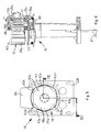
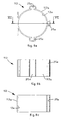
- the ventilation unit 33 has air holes, by means of which the fan 30 takes in the cooling air.
- air holes 34, 36 are made, in directions parallel to the vertical axis Y ( fig. 7 ).
- the air holes 34, 36 have an elongated section, like slits, directed radially with respect to the vertical axis Y and disposed around concentric circumferences with respect to the vertical axis Y.
- first air holes 34 are provided, which are made on the lower face 35b inside the annular wall or bushing 39, and therefore, in the final assembly, they are comprised within the bulk of the shank 20 inside the cavity 31 ( fig. 7 ).
- second air holes 36 again made on the lower face 35b but along a strip 35e, advantageously annular, which surrounds the shank 20, outside the annular wall or bushing 39 and therefore outside the relative coupling region 41 ( fig. 7 ).
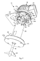
- the cooling fan 30 takes in air, by means of the air holes 34, 36, from the cooling compartment 12 and conveys and thrusts it toward the containing structure or shell 13 which houses the motor body 25, cooling it.
- the air taken under force by the cooling fan laps the external surface of the containing structure or shell 13, as indicated by the arrows F in fig. 6 , exchanging heat with the cooling fins 25a provided here.
- the motor body 25 can be closed inside the containing structure or shell 13, and is efficiently protected from water, dust, dirt or other.
- the lower side or wall 18a cooperates with the surface with cooling fins 25a so as to close the containing structure or shell 13 and to protect the motor body 25.
- the lower side or wall 18a is provided with one or more passage ways 17 that communicate on one side with the ventilation unit 33 so as to receive from the air holes 34, 36 the air taken in by the cooling fan 30, and on the other side with the external surface of the containing structure or shell 13 defined by the cooling fins 25a, thus determining a stream of cooling air outside the containing structure or shell 13, as can be seen schematized by the arrows F in fig. 6 .
- This allows to close the motor body 25 completely inside the containing structure or shell 13, in any case obtaining a good cooling by means of the stream of cold air that laps the outside of the containing structure or shell 13, exchanging heat in an extremely efficient manner with the cooling fins 25a.
- the one or more passage ways comprise a ventilation aperture or slit 17, in this case with an annular geometry, although nothing prevents the provision of other shapes, for example quadrangular, according to needs.
- the ventilation fissure 17 is made in through manner through the lower side or wall 18a, in a position outside the housing compartment 13a delimited by the containing structure or shell 13.
- the aperture or fissure 17 extends along the whole (as in the embodiment shown in the attached drawings) or part of the ideal circumference that surrounds externally the motor body 25.
- the air taken in under force by the cooling fan 30 passes through the aperture or fissure 17, lapping the cooling fins 25a so as to cool the motor body 25 from the outside, not by direct contact and heat exchange, preserving the latter from contact with water, humidity, dust, dirt or other.
- the lower side or wall 18a consists of a discoid body that has a peripheral annular portion 18c and a central region 18d.
- the peripheral annular portion 18c comprises a first annular tooth 18e, more external in a radial direction and facing downward so as to cooperate with the ventilation unit 33 below, and, more internally in a radial direction, a second annular tooth 18f, facing upward, which cooperates with the surface having cooling fins 25a so as to close the containing structure or shell 13, delimiting the housing compartment 13a.
- the aperture or fissure 17 is in a more external position than the second annular tooth 18f, in a radial direction, and is thus outside the housing compartment 13a and thus prevents water, humidity, dust, dirt or other from entering inside it, preserving the motor body 25 and its delicate components, in particular the lower bearings 44.
- the air taken in by the cooling fan 30, directly from inside the cooling compartment 12, is at a lower temperature than the outside environment.
- the ventilation unit 33 directly on the cooling compartment 12, between the shank 20 and the containing structure or shell 13 of the motor body 25 of the motor assembly 18, is that the air thus taken in allows a greater and/or quicker cooling of everything.
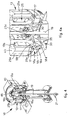
- the upper side or wall 18b of the containing structure or shell 13 is peripherally provided with deflector means to deflect the cooling air also above the containing structure or shell 13.
- the deflector means consist of an annular deflector 43 associated with the upper side or wall 18b ( figs. 4, 4a , 5 and 6 ) by means of which the air arriving from the ventilation unit 33 and which has made a heat exchange also with the cooling fins 25a, is deflected and conveyed centrally.
- the annular deflector 43 is shaped like a truncated cone that progressively narrows from the bottom up, constituting a narrowing in the section which the cooling air passes through, which is thus deflected and accelerated in correspondence with the upper part of the containing structure or shell 13, improving heat exchange and cooling, in particular of the upper side or wall 18b, as can be seen clearly from the travel path of the arrow F' in fig. 6 . Consequently, with this solution, the cooling air does not leave the upper part of the containing structure or shell 13 quickly, and on the contrary is suitably deflected so as to affect, at least partly, the upper side or wall 18b as well.
- the upper side or wall 18b has a central body 43a and protruding radial portions 43b which function as a support and spacer for the annular deflector 43, alternating with windows 43c.
- the air is deflected by the annular deflector 43 and forcedly conveyed through the windows 43c toward the upper side or wall 18b, so as to obtain the desired cooling effect.
- third air holes 38 are also made, through in a radial direction, along a circumference centered on the vertical axis Y ( fig. 7 ).
- the present invention provides fourth air holes 38a, made on the lateral surface of the containing element 35 of the ventilation unit 33 ( fig. 7 ), in the external part of the containing tank 14, in this case above the upper wall 16.
- the fourth air holes 38a made laterally on the ventilation unit 33, perform an advantageous safety function in that they guarantee that the cooling fan 30 can always take in an adequate quantity of air, taken from the surrounding environment, even when the cavity 31 of the shank 20 rapidly fills with water until it reaches the level of the lower face 35b, preventing any air being taken in through the holes made on the same lower face 35b.
- the hydraulic pumping member 23 comprises an element 23a, in this case substantially disk-shaped ( fig. 7 ), supported by the lower end 20a of the shank 20, inside which a hydraulic chamber 22 is made, able to house the hydraulic rotor or turbine 24, or other hydraulic element suitable for pumping.
- the hydraulic rotor 24 is directly attached to the drive shaft 19, which makes it rotate to pump the water 11 toward a distributor element 26, which, by means of an exit or delivery pipe 27, of which only a part is shown in fig. 3 , by a line of dashes, sends the cooling water toward the delivery circuit and from here toward the final user machine to be cooled.
- a distributor element 26 which, by means of an exit or delivery pipe 27, of which only a part is shown in fig. 3 , by a line of dashes, sends the cooling water toward the delivery circuit and from here toward the final user machine to be cooled.
- cooling is achieved also during the passage in the delivery circuit and in this case, there is also a second circuit present, called return circuit, to recover the cooling water (not shown in the drawings).
- the embodiment shown in figs. 1-7 shows the device 10 which, apart from pumping the liquid, can also function as a stirrer for the liquid.
- a stirrer element 21 is mounted, in this case a screw, which, rotating together with the drive shaft 19, stirs the surrounding water, slowing down the formation of ice and promoting the erosion of the layers of ice that form at the sides of the containing tank 14.
- a constructional variant, shown in figs. 8a, 8b and 8c , provides that the lateral surface of the containing structure or shell 13, indicated by the reference number 113, includes ventilation channels, chambers or interstices 25e, in this case as an alternative to - but they could also be in association with - the cooling fins 25a, along which the cooling air is conveyed by the action of the cooling fan 30, again for the purposes of cooling the motor body 25 from the outside.
- the ventilation channels or chambers 25e are made externally on the lateral surface 113a of the containing structure or shell 113, and have a closed cross section or profile ( fig. 8a ) and longitudinal development ( figs.
- the ventilation channels or chambers 25e can be made around the lateral surface of the containing structure or shell 13 with a constant angular pitch, or variable according to needs.
- the ventilation channels or chambers 25e can be interspersed and combined with surfaces having cooling fins 25.
- fig. 9 shows a variant assembly of the movement device according to the present invention, in which the device is mounted above a wall 51 of the refrigeration unit 50, attached above the wall 51 by means of the flange 28.
- the containing tank 14 is inside the refrigeration unit 50, and the device 10 is disposed inside it.
- Fig. 10 shows another variant assembly of the movement device according to the present invention.
- the device 10 is mounted suspended below the wall 51 of the refrigeration unit, attached to the lower part of the wall 51 by means of attachment elements 52, such as screws or other.
- attachment elements 52 such as screws or other.
- the containing tank 14 is inside the refrigeration unit 50, and the device 10 is disposed inside it.
- Fig. 11 is a constructional variant in which the movement device according to the present invention, indicated for convenience by the reference number 110, has the screw-type stirrer element 21 only, attached to the lower end of the drive shaft 19, with the function of stirring the liquid in the tank 12.
- the device 110 is used only for the purposes of stirring the liquid, and therefore does not provide the hydraulic pumping member 23 or the shank 20 that supports it.
- the variant device 110 maintains all the advantages of distancing the motor assembly 18 from the level of liquid in the tank 12, preserving the members of the motor, the bearings, coils and rotor, from flooding, in particular the lower bearings 44.
Landscapes
- Engineering & Computer Science (AREA)
- Power Engineering (AREA)
- Chemical & Material Sciences (AREA)
- Chemical Kinetics & Catalysis (AREA)
- Physics & Mathematics (AREA)
- Thermal Sciences (AREA)
- Structures Of Non-Positive Displacement Pumps (AREA)
- Other Liquid Machine Or Engine Such As Wave Power Use (AREA)
- Catching Or Destruction (AREA)
- Separation Using Semi-Permeable Membranes (AREA)
Claims (18)
- Vorrichtung zum Bewegen einer Flüssigkeit (11), welche, entlang einer gemeinsamen Achse (Y) angeordnet, enthält:eine Motoranordnung (18),eine Ventilationseinheit (33) zum Kühlen der Motoranordnung (18),Bewegungselemente (21, 23), welche kinematisch mit der Motoranordnung (18) verbunden sind, wobei die Bewegungselemente (21, 23) dazu ausgelegt sind, zumindest teilweise in die Flüssigkeit (11) eingetaucht zu werden, und welche durch die Motoranordnung (18) angetrieben werden können, um die Flüssigkeit (11) zu bewegen,dadurch gekennzeichnet, dass die Ventilationseinheit (33) entlang der Achse (Y), zwischen der Motoranordnung (18) und den Bewegungselementen (21, 23), angeordnet ist, um somit die Motoranordnung (18) von der Flüssigkeit (11) zu distanzieren, wobei die Motoranordnung (18) einen Behältnisaufbau (13, 113) enthält, welcher in der Nähe zu der Ventilationseinheit (33) und einem Motorkörper (25) angeordnet ist, wobei der Behältnisaufbau (13, 113) vom geschlossenen Typ ist und im Inneren eine Behälterkammer (13a) hat, in welcher der Motorkörper (25) positioniert ist, wobei der Motorkörper (25) bezogen auf die Außenwelt im Wesentlichen isoliert ist, wobei der Behältnisaufbau (13, 113) einen oder mehrere Durchgänge (17) außerhalb der Behälterkammer (13a) hat, welche an einer Seite mit der Ventilationseinheit (33) und an der anderen Seite mit der Außenseite des Behältnisaufbaus (13, 113) in Verbindung stehen, wobei der Durchgang von Kühlluft, welche von der Ventilationseinheit (33) ankommt, durch den einen oder die mehreren Durchgänge (17) auftritt, wobei der eine oder die mehreren Durchgänge (17) ausgelegt sind, die Kühlluft entlang der Außenfläche des Behältnisaufbaus (13, 113) zu richten, um somit die Motoranordnung (18) zu kühlen.
- Vorrichtung nach Anspruch 1, dadurch gekennzeichnet, dass der Behältnisaufbau (13, 113) außerhalb, zumindest an der Seitenfläche, Wärmetauschelemente (25a, 25e) hat, welche zum Wärmetausch mit der Kühlluft, welche durch den einen oder die mehreren Durchgänge (17) von der Ventilationseinheit (33) ankommt, geeignet sind, um somit den Motorkörper (25) indirekt zu kühlen.
- Vorrichtung nach Anspruch 1 oder 2, dadurch gekennzeichnet, dass der Behältnisaufbau (13, 113) ein Ablenkelement (43) am oberen Teil hat, welches ausgelegt ist, die Kühlluft von der Ventilationseinheit (33) zu einer oberen Seite (18b) des Behältnisaufbaus (13, 113) abzulenken.
- Vorrichtung nach einem der Ansprüche 1 bis 3, dadurch gekennzeichnet, dass die Ventilationseinheit (33) direkt mit einer unteren Seite (18a) des Behältnisaufbaus (13, 113) der Motoranordnung (18) verbunden ist.
- Vorrichtung nach einem der vorhergehenden Ansprüche, dadurch gekennzeichnet, dass sie einen Halteaufbau (20) enthält, welcher dazu ausgelegt ist, die Bewegungselemente (21, 23) zu halten, welcher an einer Seite mit den Bewegungselementen (21, 23) und an der anderen Seite mit der Ventilationseinheit (33) verbunden ist.
- Vorrichtung nach einem der vorhergehenden Ansprüche, dadurch gekennzeichnet, dass die Ventilationseinheit (33) im Inneren einen Kühllüfter (30) und ein Behältniselement (35) enthält, welches einen Belüftungssitz (32) hat, innerhalb dessen der Kühllüfter (30) gelagert ist, wobei das Behältniselement (35) eine obere Öffnung (35d), mittels derer der Kühllüfter (30) zur Motoranordnung (18) gerichtet ist, und eine untere Wand (35b), durch welche der Kühllüfter (30) Luft aufnimmt, hat.
- Vorrichtung nach Anspruch 6, dadurch gekennzeichnet, dass sie eine Vielzahl von Luftlöchern (34, 36) hat, welche an der unteren Wand (35b) erstellt sind, durch welche der Kühllüfter (30) die Luft zum Kühlen der Motoranordnung (18) aufnimmt.
- Vorrichtung nach Anspruch 6 oder 7, dadurch gekennzeichnet, dass sie ein Verbindungselement (39) enthält, welches sich von der unteren Wand (35b) erstreckt, zur Verbindung mit dem Halteaufbau (20), um somit einen festgelegten Kopplungsbereich (41) zu bestimmen.
- Vorrichtung nach Anspruch 7 oder 8, dadurch gekennzeichnet, dass die Luftlöcher erste Löcher (34), welche innerhalb des Verbindungselements (39) erstellt sind, und zweite Löcher (36), welche außerhalb des Kopplungsbereichs (41) zwischen dem Verbindungselement (39) und dem Halteaufbau (20) angeordnet sind, enthalten.
- Vorrichtung nach Anspruch 8 oder 9, dadurch gekennzeichnet, dass sie dritte Luftlöcher (38) hat, welche an der Seitenfläche des Verbindungselements (39) erstellt sind.
- Vorrichtung nach einem der vorhergehenden Ansprüche, dadurch gekennzeichnet, dass sie vierte Luftlöcher (38a) hat, welche an der Seitenfläche der Ventilationseinheit (33) erstellt sind.
- Vorrichtung nach Anspruch 6, dadurch gekennzeichnet, dass das Behältniselement der Ventilationseinheit (33) durch einen einzelnen Körper ausgebildet ist, welcher derart geformt ist, dass er einen Kühllüfter mit einer Relativkammer zum Fördern der Kühlluft zur Motoranordnung (18) bestimmt.
- Vorrichtung nach Anspruch 5, dadurch gekennzeichnet, dass die Bewegungselemente ein Hydraulikpumpenelement (23) enthalten, wobei der Halteaufbau (20) einstückig mit der Ventilationseinheit (33) und mit dem Hydraulikpumpenelement (23) erstellt ist.
- Vorrichtung nach einem der vorhergehenden Ansprüche, dadurch gekennzeichnet, dass die Achse (Y) vertikal ausgerichtet ist.
- Kühleinheit, welche enthält:einen Behälter oder einen Behältertank (14), welcher eine Kühlkammer (12) hat, in welcher eine Kühlflüssigkeit (11) enthalten ist;eine Vorrichtung (10, 110) zum Bewegen der Flüssigkeit (11) nach einem der vorhergehenden Ansprüche, welche, zumindest teilweise in der Kühlkammer (12) eingesetzt, oberhalb des Behälters oder des Behältertanks (14) befestigt ist.
- Einheit nach Anspruch 15, dadurch gekennzeichnet, dass die Vorrichtung (10, 110) oberhalb einer oberen Wand (16) des Behälters oder des Behältertanks (14) befestigt ist, wobei sie mittels Befestigungselemente (28) an der oberen Wand (16) angebracht ist und durch eine Öffnung (15) im Behälter oder Behältertank (14) eingesetzt ist.
- Einheit nach Anspruch 15, dadurch gekennzeichnet, dass die Vorrichtung (10,110) oberhalb einer oberen Wand (51) der Kühleinheit befestigt ist, wobei sie mittels Befestigungselemente (28) an der oberen Wand (51) angebracht ist und durch eine Öffnung (15) eingesetzt ist, welche im Behälter oder Behältertank (14) bereitgestellt ist.
- Einheit nach Anspruch 15, dadurch gekennzeichnet, dass die Vorrichtung (10,110) unterhalb einer oberen Wand (51) der Kühleinheit aufgehängt befestigt ist, wobei sie mittels Befestigungselemente (28) an der oberen Wand (51) angebracht ist und durch eine Öffnung (15) im Behälter oder Behältertank (14) eingesetzt ist.
Applications Claiming Priority (1)
| Application Number | Priority Date | Filing Date | Title |
|---|---|---|---|
| ITUD2009A000072A IT1394255B1 (it) | 2009-04-08 | 2009-04-08 | Dispositivo per la movimentazione di un liquido, di tipo verticale semi-sommerso |
Publications (2)
| Publication Number | Publication Date |
|---|---|
| EP2241759A1 EP2241759A1 (de) | 2010-10-20 |
| EP2241759B1 true EP2241759B1 (de) | 2012-06-20 |
Family
ID=41478768
Family Applications (1)
| Application Number | Title | Priority Date | Filing Date |
|---|---|---|---|
| EP10159200A Active EP2241759B1 (de) | 2009-04-08 | 2010-04-07 | Halb eingetauchte, vertikale Vorrichtung zum Bewegen einer Flüssigkeit |
Country Status (3)
| Country | Link |
|---|---|
| EP (1) | EP2241759B1 (de) |
| ES (1) | ES2389939T3 (de) |
| IT (1) | IT1394255B1 (de) |
Families Citing this family (1)
| Publication number | Priority date | Publication date | Assignee | Title |
|---|---|---|---|---|
| CN113162331B (zh) * | 2021-03-31 | 2023-03-31 | 内蒙古北方龙源风力发电有限责任公司 | 风力双馈发电机循环冷却装置 |
Family Cites Families (4)
| Publication number | Priority date | Publication date | Assignee | Title |
|---|---|---|---|---|
| US4670677A (en) * | 1986-04-25 | 1987-06-02 | Emerson Electric Co. | Electric motor with shrouded fan |
| US6059535A (en) * | 1998-01-22 | 2000-05-09 | Process Systems, Inc. | Pump with air purging and self-cleaning features |
| DE29818704U1 (de) * | 1998-10-21 | 1998-12-24 | Grundfos A/S, Bjerringbro | Motorgetriebene Doppelpumpe der Kreiselpumpenbauart |
| DE29820792U1 (de) * | 1998-11-20 | 1999-03-25 | Casagrande, Luigino, 22844 Norderstedt | Pumpe für Flüssigkeiten, insbesondere für Getränke |
-
2009
- 2009-04-08 IT ITUD2009A000072A patent/IT1394255B1/it active
-
2010
- 2010-04-07 ES ES10159200T patent/ES2389939T3/es active Active
- 2010-04-07 EP EP10159200A patent/EP2241759B1/de active Active
Also Published As
| Publication number | Publication date |
|---|---|
| EP2241759A1 (de) | 2010-10-20 |
| ITUD20090072A1 (it) | 2010-10-09 |
| IT1394255B1 (it) | 2012-06-01 |
| ES2389939T3 (es) | 2012-11-05 |
Similar Documents
| Publication | Publication Date | Title |
|---|---|---|
| EP2616687B1 (de) | Kühlsysteme für tauchpumpen | |
| KR101042028B1 (ko) | 모터 펌프 | |
| JP6082476B2 (ja) | 液体圧送用ポンプの冷却構成 | |
| JP4655181B2 (ja) | 冷却水封入形熱交換器付乾式水中モータポンプ | |
| EP0990800A1 (de) | Geschlossener Zwangskühlkreislauf für den Motor einer Tauchpumpe | |
| EP3388666A1 (de) | Schmiersystem für einen antriebsstrang einer windturbine, windturbine und verfahren zur schmierung | |
| JP2008267215A (ja) | ポンプ設備 | |
| AU2002300182B2 (en) | A Pump | |
| EP2241759B1 (de) | Halb eingetauchte, vertikale Vorrichtung zum Bewegen einer Flüssigkeit | |
| JP5707086B2 (ja) | 排水ポンプ | |
| KR101784909B1 (ko) | 수중모터펌프의 냉각장치 | |
| EP0141599B1 (de) | Schmiermittelbehälter für Reaktorkühlmittelpumpenmotor und Einrichtung zur Überwachung des Schmiermittelniveaus | |
| JP3251838B2 (ja) | 縦型回転機械の軸受装置 | |
| US9217436B2 (en) | Impeller fan assembly | |
| JP3015089B2 (ja) | 横軸回転機の軸受装置 | |
| US20060171800A1 (en) | Drain pump and air conditioner with the same | |
| JPH10205499A (ja) | 竪型電動ポンプのモータ冷却装置 | |
| US5941695A (en) | Submersible motor for driving a centrifugal pump having a separating wall disposed in a rotor chamber-space | |
| US20030124002A1 (en) | Pump | |
| EP2878826B1 (de) | Pumpe mit luftgekühltem Motor | |
| US10519958B2 (en) | Systems and methods to provide lubricant to a bearing | |
| KR20200042148A (ko) | 전동식 워터펌프용 임펠러 | |
| KR20120106174A (ko) | 펌프장용 배수 펌프장치 | |
| KR200421875Y1 (ko) | 원유펌프용 전동기의 오일순환구조 | |
| US2504899A (en) | Bearing bracket for hydrogencooled generators |
Legal Events
| Date | Code | Title | Description |
|---|---|---|---|
| PUAI | Public reference made under article 153(3) epc to a published international application that has entered the european phase |
Free format text: ORIGINAL CODE: 0009012 |
|
| AK | Designated contracting states |
Kind code of ref document: A1 Designated state(s): AT BE BG CH CY CZ DE DK EE ES FI FR GB GR HR HU IE IS IT LI LT LU LV MC MK MT NL NO PL PT RO SE SI SK SM TR |
|
| AX | Request for extension of the european patent |
Extension state: AL BA ME RS |
|
| 17P | Request for examination filed |
Effective date: 20110419 |
|
| RIC1 | Information provided on ipc code assigned before grant |
Ipc: F04D 13/08 20060101AFI20111004BHEP Ipc: H02K 9/06 20060101ALI20111004BHEP |
|
| GRAP | Despatch of communication of intention to grant a patent |
Free format text: ORIGINAL CODE: EPIDOSNIGR1 |
|
| GRAS | Grant fee paid |
Free format text: ORIGINAL CODE: EPIDOSNIGR3 |
|
| GRAA | (expected) grant |
Free format text: ORIGINAL CODE: 0009210 |
|
| AK | Designated contracting states |
Kind code of ref document: B1 Designated state(s): AT BE BG CH CY CZ DE DK EE ES FI FR GB GR HR HU IE IS IT LI LT LU LV MC MK MT NL NO PL PT RO SE SI SK SM TR |
|
| REG | Reference to a national code |
Ref country code: GB Ref legal event code: FG4D |
|
| REG | Reference to a national code |
Ref country code: CH Ref legal event code: EP |
|
| REG | Reference to a national code |
Ref country code: AT Ref legal event code: REF Ref document number: 563228 Country of ref document: AT Kind code of ref document: T Effective date: 20120715 |
|
| REG | Reference to a national code |
Ref country code: IE Ref legal event code: FG4D |
|
| REG | Reference to a national code |
Ref country code: DE Ref legal event code: R096 Ref document number: 602010001898 Country of ref document: DE Effective date: 20120816 |
|
| PG25 | Lapsed in a contracting state [announced via postgrant information from national office to epo] |
Ref country code: FI Free format text: LAPSE BECAUSE OF FAILURE TO SUBMIT A TRANSLATION OF THE DESCRIPTION OR TO PAY THE FEE WITHIN THE PRESCRIBED TIME-LIMIT Effective date: 20120620 Ref country code: LT Free format text: LAPSE BECAUSE OF FAILURE TO SUBMIT A TRANSLATION OF THE DESCRIPTION OR TO PAY THE FEE WITHIN THE PRESCRIBED TIME-LIMIT Effective date: 20120620 Ref country code: NO Free format text: LAPSE BECAUSE OF FAILURE TO SUBMIT A TRANSLATION OF THE DESCRIPTION OR TO PAY THE FEE WITHIN THE PRESCRIBED TIME-LIMIT Effective date: 20120920 Ref country code: SE Free format text: LAPSE BECAUSE OF FAILURE TO SUBMIT A TRANSLATION OF THE DESCRIPTION OR TO PAY THE FEE WITHIN THE PRESCRIBED TIME-LIMIT Effective date: 20120620 |
|
| REG | Reference to a national code |
Ref country code: ES Ref legal event code: FG2A Ref document number: 2389939 Country of ref document: ES Kind code of ref document: T3 Effective date: 20121105 |
|
| REG | Reference to a national code |
Ref country code: NL Ref legal event code: VDEP Effective date: 20120620 |
|
| REG | Reference to a national code |
Ref country code: AT Ref legal event code: MK05 Ref document number: 563228 Country of ref document: AT Kind code of ref document: T Effective date: 20120620 |
|
| REG | Reference to a national code |
Ref country code: LT Ref legal event code: MG4D Effective date: 20120620 |
|
| PG25 | Lapsed in a contracting state [announced via postgrant information from national office to epo] |
Ref country code: SI Free format text: LAPSE BECAUSE OF FAILURE TO SUBMIT A TRANSLATION OF THE DESCRIPTION OR TO PAY THE FEE WITHIN THE PRESCRIBED TIME-LIMIT Effective date: 20120620 Ref country code: LV Free format text: LAPSE BECAUSE OF FAILURE TO SUBMIT A TRANSLATION OF THE DESCRIPTION OR TO PAY THE FEE WITHIN THE PRESCRIBED TIME-LIMIT Effective date: 20120620 Ref country code: GR Free format text: LAPSE BECAUSE OF FAILURE TO SUBMIT A TRANSLATION OF THE DESCRIPTION OR TO PAY THE FEE WITHIN THE PRESCRIBED TIME-LIMIT Effective date: 20120921 Ref country code: HR Free format text: LAPSE BECAUSE OF FAILURE TO SUBMIT A TRANSLATION OF THE DESCRIPTION OR TO PAY THE FEE WITHIN THE PRESCRIBED TIME-LIMIT Effective date: 20120620 |
|
| PG25 | Lapsed in a contracting state [announced via postgrant information from national office to epo] |
Ref country code: CZ Free format text: LAPSE BECAUSE OF FAILURE TO SUBMIT A TRANSLATION OF THE DESCRIPTION OR TO PAY THE FEE WITHIN THE PRESCRIBED TIME-LIMIT Effective date: 20120620 Ref country code: EE Free format text: LAPSE BECAUSE OF FAILURE TO SUBMIT A TRANSLATION OF THE DESCRIPTION OR TO PAY THE FEE WITHIN THE PRESCRIBED TIME-LIMIT Effective date: 20120620 Ref country code: AT Free format text: LAPSE BECAUSE OF FAILURE TO SUBMIT A TRANSLATION OF THE DESCRIPTION OR TO PAY THE FEE WITHIN THE PRESCRIBED TIME-LIMIT Effective date: 20120620 Ref country code: SK Free format text: LAPSE BECAUSE OF FAILURE TO SUBMIT A TRANSLATION OF THE DESCRIPTION OR TO PAY THE FEE WITHIN THE PRESCRIBED TIME-LIMIT Effective date: 20120620 Ref country code: RO Free format text: LAPSE BECAUSE OF FAILURE TO SUBMIT A TRANSLATION OF THE DESCRIPTION OR TO PAY THE FEE WITHIN THE PRESCRIBED TIME-LIMIT Effective date: 20120620 Ref country code: CY Free format text: LAPSE BECAUSE OF FAILURE TO SUBMIT A TRANSLATION OF THE DESCRIPTION OR TO PAY THE FEE WITHIN THE PRESCRIBED TIME-LIMIT Effective date: 20120620 Ref country code: BE Free format text: LAPSE BECAUSE OF FAILURE TO SUBMIT A TRANSLATION OF THE DESCRIPTION OR TO PAY THE FEE WITHIN THE PRESCRIBED TIME-LIMIT Effective date: 20120620 Ref country code: IS Free format text: LAPSE BECAUSE OF FAILURE TO SUBMIT A TRANSLATION OF THE DESCRIPTION OR TO PAY THE FEE WITHIN THE PRESCRIBED TIME-LIMIT Effective date: 20121020 |
|
| PG25 | Lapsed in a contracting state [announced via postgrant information from national office to epo] |
Ref country code: PL Free format text: LAPSE BECAUSE OF FAILURE TO SUBMIT A TRANSLATION OF THE DESCRIPTION OR TO PAY THE FEE WITHIN THE PRESCRIBED TIME-LIMIT Effective date: 20120620 Ref country code: PT Free format text: LAPSE BECAUSE OF FAILURE TO SUBMIT A TRANSLATION OF THE DESCRIPTION OR TO PAY THE FEE WITHIN THE PRESCRIBED TIME-LIMIT Effective date: 20121022 |
|
| PG25 | Lapsed in a contracting state [announced via postgrant information from national office to epo] |
Ref country code: NL Free format text: LAPSE BECAUSE OF FAILURE TO SUBMIT A TRANSLATION OF THE DESCRIPTION OR TO PAY THE FEE WITHIN THE PRESCRIBED TIME-LIMIT Effective date: 20120620 |
|
| PLBE | No opposition filed within time limit |
Free format text: ORIGINAL CODE: 0009261 |
|
| STAA | Information on the status of an ep patent application or granted ep patent |
Free format text: STATUS: NO OPPOSITION FILED WITHIN TIME LIMIT |
|
| PG25 | Lapsed in a contracting state [announced via postgrant information from national office to epo] |
Ref country code: DK Free format text: LAPSE BECAUSE OF FAILURE TO SUBMIT A TRANSLATION OF THE DESCRIPTION OR TO PAY THE FEE WITHIN THE PRESCRIBED TIME-LIMIT Effective date: 20120620 |
|
| 26N | No opposition filed |
Effective date: 20130321 |
|
| REG | Reference to a national code |
Ref country code: DE Ref legal event code: R097 Ref document number: 602010001898 Country of ref document: DE Effective date: 20130321 |
|
| PG25 | Lapsed in a contracting state [announced via postgrant information from national office to epo] |
Ref country code: BG Free format text: LAPSE BECAUSE OF FAILURE TO SUBMIT A TRANSLATION OF THE DESCRIPTION OR TO PAY THE FEE WITHIN THE PRESCRIBED TIME-LIMIT Effective date: 20120920 |
|
| PG25 | Lapsed in a contracting state [announced via postgrant information from national office to epo] |
Ref country code: MC Free format text: LAPSE BECAUSE OF FAILURE TO SUBMIT A TRANSLATION OF THE DESCRIPTION OR TO PAY THE FEE WITHIN THE PRESCRIBED TIME-LIMIT Effective date: 20120620 |
|
| REG | Reference to a national code |
Ref country code: IE Ref legal event code: MM4A |
|
| PG25 | Lapsed in a contracting state [announced via postgrant information from national office to epo] |
Ref country code: IE Free format text: LAPSE BECAUSE OF NON-PAYMENT OF DUE FEES Effective date: 20130407 |
|
| REG | Reference to a national code |
Ref country code: CH Ref legal event code: PL |
|
| PG25 | Lapsed in a contracting state [announced via postgrant information from national office to epo] |
Ref country code: LI Free format text: LAPSE BECAUSE OF NON-PAYMENT OF DUE FEES Effective date: 20140430 Ref country code: CH Free format text: LAPSE BECAUSE OF NON-PAYMENT OF DUE FEES Effective date: 20140430 |
|
| PG25 | Lapsed in a contracting state [announced via postgrant information from national office to epo] |
Ref country code: MT Free format text: LAPSE BECAUSE OF FAILURE TO SUBMIT A TRANSLATION OF THE DESCRIPTION OR TO PAY THE FEE WITHIN THE PRESCRIBED TIME-LIMIT Effective date: 20120620 |
|
| PG25 | Lapsed in a contracting state [announced via postgrant information from national office to epo] |
Ref country code: SM Free format text: LAPSE BECAUSE OF FAILURE TO SUBMIT A TRANSLATION OF THE DESCRIPTION OR TO PAY THE FEE WITHIN THE PRESCRIBED TIME-LIMIT Effective date: 20120620 |
|
| PG25 | Lapsed in a contracting state [announced via postgrant information from national office to epo] |
Ref country code: TR Free format text: LAPSE BECAUSE OF FAILURE TO SUBMIT A TRANSLATION OF THE DESCRIPTION OR TO PAY THE FEE WITHIN THE PRESCRIBED TIME-LIMIT Effective date: 20120620 |
|
| PG25 | Lapsed in a contracting state [announced via postgrant information from national office to epo] |
Ref country code: MK Free format text: LAPSE BECAUSE OF FAILURE TO SUBMIT A TRANSLATION OF THE DESCRIPTION OR TO PAY THE FEE WITHIN THE PRESCRIBED TIME-LIMIT Effective date: 20120620 Ref country code: LU Free format text: LAPSE BECAUSE OF NON-PAYMENT OF DUE FEES Effective date: 20130407 Ref country code: HU Free format text: LAPSE BECAUSE OF FAILURE TO SUBMIT A TRANSLATION OF THE DESCRIPTION OR TO PAY THE FEE WITHIN THE PRESCRIBED TIME-LIMIT; INVALID AB INITIO Effective date: 20100407 |
|
| REG | Reference to a national code |
Ref country code: FR Ref legal event code: PLFP Year of fee payment: 7 |
|
| REG | Reference to a national code |
Ref country code: FR Ref legal event code: PLFP Year of fee payment: 8 |
|
| REG | Reference to a national code |
Ref country code: FR Ref legal event code: PLFP Year of fee payment: 9 |
|
| P01 | Opt-out of the competence of the unified patent court (upc) registered |
Effective date: 20230426 |
|
| PGFP | Annual fee paid to national office [announced via postgrant information from national office to epo] |
Ref country code: IT Payment date: 20240207 Year of fee payment: 15 |
|
| PGFP | Annual fee paid to national office [announced via postgrant information from national office to epo] |
Ref country code: DE Payment date: 20250410 Year of fee payment: 16 |
|
| PGFP | Annual fee paid to national office [announced via postgrant information from national office to epo] |
Ref country code: ES Payment date: 20250507 Year of fee payment: 16 Ref country code: GB Payment date: 20250411 Year of fee payment: 16 |
|
| PGFP | Annual fee paid to national office [announced via postgrant information from national office to epo] |
Ref country code: FR Payment date: 20250410 Year of fee payment: 16 |