EP2241752B2 - Système de pompe - Google Patents
Système de pompe Download PDFInfo
- Publication number
- EP2241752B2 EP2241752B2 EP10170292.6A EP10170292A EP2241752B2 EP 2241752 B2 EP2241752 B2 EP 2241752B2 EP 10170292 A EP10170292 A EP 10170292A EP 2241752 B2 EP2241752 B2 EP 2241752B2
- Authority
- EP
- European Patent Office
- Prior art keywords
- pump
- gear
- housing
- rotary drive
- drive device
- Prior art date
- Legal status (The legal status is an assumption and is not a legal conclusion. Google has not performed a legal analysis and makes no representation as to the accuracy of the status listed.)
- Ceased
Links
- 238000005086 pumping Methods 0.000 title description 2
- 239000007788 liquid Substances 0.000 claims description 13
- 230000005540 biological transmission Effects 0.000 claims description 4
- 230000008878 coupling Effects 0.000 claims description 2
- 238000010168 coupling process Methods 0.000 claims description 2
- 238000005859 coupling reaction Methods 0.000 claims description 2
- 238000005553 drilling Methods 0.000 description 7
- 238000011010 flushing procedure Methods 0.000 description 5
- 230000002000 scavenging effect Effects 0.000 description 4
- 238000005520 cutting process Methods 0.000 description 3
- 239000012530 fluid Substances 0.000 description 2
- 235000009508 confectionery Nutrition 0.000 description 1
- 230000002262 irrigation Effects 0.000 description 1
- 238000003973 irrigation Methods 0.000 description 1
- 238000000034 method Methods 0.000 description 1
- 238000007789 sealing Methods 0.000 description 1
Images

Classifications
-
- F—MECHANICAL ENGINEERING; LIGHTING; HEATING; WEAPONS; BLASTING
- F04—POSITIVE - DISPLACEMENT MACHINES FOR LIQUIDS; PUMPS FOR LIQUIDS OR ELASTIC FLUIDS
- F04B—POSITIVE-DISPLACEMENT MACHINES FOR LIQUIDS; PUMPS
- F04B1/00—Multi-cylinder machines or pumps characterised by number or arrangement of cylinders
- F04B1/005—Pumps with cylinder axis arranged substantially tangentially to a circle centred on main shaft axis
-
- F—MECHANICAL ENGINEERING; LIGHTING; HEATING; WEAPONS; BLASTING
- F04—POSITIVE - DISPLACEMENT MACHINES FOR LIQUIDS; PUMPS FOR LIQUIDS OR ELASTIC FLUIDS
- F04B—POSITIVE-DISPLACEMENT MACHINES FOR LIQUIDS; PUMPS
- F04B9/00—Piston machines or pumps characterised by the driving or driven means to or from their working members
- F04B9/02—Piston machines or pumps characterised by the driving or driven means to or from their working members the means being mechanical
-
- E—FIXED CONSTRUCTIONS
- E21—EARTH OR ROCK DRILLING; MINING
- E21B—EARTH OR ROCK DRILLING; OBTAINING OIL, GAS, WATER, SOLUBLE OR MELTABLE MATERIALS OR A SLURRY OF MINERALS FROM WELLS
- E21B21/00—Methods or apparatus for flushing boreholes, e.g. by use of exhaust air from motor
- E21B21/08—Controlling or monitoring pressure or flow of drilling fluid, e.g. automatic filling of boreholes, automatic control of bottom pressure
-
- F—MECHANICAL ENGINEERING; LIGHTING; HEATING; WEAPONS; BLASTING
- F01—MACHINES OR ENGINES IN GENERAL; ENGINE PLANTS IN GENERAL; STEAM ENGINES
- F01C—ROTARY-PISTON OR OSCILLATING-PISTON MACHINES OR ENGINES
- F01C21/00—Component parts, details or accessories not provided for in groups F01C1/00 - F01C20/00
- F01C21/007—General arrangements of parts; Frames and supporting elements
-
- F—MECHANICAL ENGINEERING; LIGHTING; HEATING; WEAPONS; BLASTING
- F04—POSITIVE - DISPLACEMENT MACHINES FOR LIQUIDS; PUMPS FOR LIQUIDS OR ELASTIC FLUIDS
- F04B—POSITIVE-DISPLACEMENT MACHINES FOR LIQUIDS; PUMPS
- F04B17/00—Pumps characterised by combination with, or adaptation to, specific driving engines or motors
- F04B17/03—Pumps characterised by combination with, or adaptation to, specific driving engines or motors driven by electric motors
-
- F—MECHANICAL ENGINEERING; LIGHTING; HEATING; WEAPONS; BLASTING
- F04—POSITIVE - DISPLACEMENT MACHINES FOR LIQUIDS; PUMPS FOR LIQUIDS OR ELASTIC FLUIDS
- F04C—ROTARY-PISTON, OR OSCILLATING-PISTON, POSITIVE-DISPLACEMENT MACHINES FOR LIQUIDS; ROTARY-PISTON, OR OSCILLATING-PISTON, POSITIVE-DISPLACEMENT PUMPS
- F04C15/00—Component parts, details or accessories of machines, pumps or pumping installations, not provided for in groups F04C2/00 - F04C14/00
- F04C15/0057—Driving elements, brakes, couplings, transmission specially adapted for machines or pumps
- F04C15/0061—Means for transmitting movement from the prime mover to driven parts of the pump, e.g. clutches, couplings, transmissions
Definitions
- the invention relates to a rinsing liquid pump system, with a pump unit and with a rotary drive device for driving the pump unit.
- flushing liquid pump system refers to a pump system which conveys flushing liquid which flushes through the borehole during the advance or drilling of boreholes.
- flushing fluid is supplied to the borehole during the drilling process.
- the flushing liquid is used on the one hand to lubricate the drilling tools working on the working face or on the bottom of the borehole and to support the working face or the borehole wall.
- loosened drill cuttings can also be brought out of the borehole, for example by supplying fresh rinsing liquid centrally through a hollow drill string in the area of the bottom of the borehole or the working face, thus generating a rinsing liquid flow that entrains loosened drill cuttings and out of the drilling out.
- the pumping capacity of such pump systems is regularly in the range of a maximum of 3000 l/min and a maximum pressure of 500 bar.
- the state of the art includes pump systems which are distinguished by a particularly compact design, since the rotary drive device of the pump system which drives the pump assembly is arranged above the pump assembly and is flanged to the upper side of the housing.
- the rotary drive devices regularly have outputs of up to 1,700 kW.
- the GB-A-1034058 concerns improvements to a sun and planetary gear. Although this document discloses using these improvements, which comprise a rotary drive device and a gear train comprising a drive wheel and a driven wheel, in connection with a pump arrangement, this is intended for use in the confectionery industry. This document therefore does not contain any indications as to how to design a rinsing liquid pump system in the manner according to the invention.
- the U.S. 2004/0060717 A1 relates to a drilling device with a compact compressor-pump arrangement.
- the pumps are hydraulic pumps which are used to provide the pressure required to actuate the drilling device, for example rotating and positioning the mast, by means of hydraulic cylinders or hydraulic motors.
- the compressor is used to produce compressed air, which is used to extract drill cuttings from the well.
- the compressor and pumps are flanged together into one unit and connected via gears to a drive axle driven by a rotary motor. Again, the subject of this document is not an irrigation fluid pump.
- the U.S. 2004/0028540 A1 refers to a manually driven pump or compressor assembly. Although in the embodiment shown in FIG. 3 an operative connection is established between the manual drive and the pump or compressor device by means of meshing gear wheels, this document has no connection with a rinsing liquid pump system.
- the U.S. 2004/0219040 A1 shows a device with a summation gear, which is used to bundle the power of several motors. This document does not contain suggestions for a rinsing liquid pump system with precisely one rotary drive device.
- the US2004/0219042 shows a pump arrangement with a motor.
- the CN 2 385 075 Y discloses a mud pump assembly. It comprises a pump housing in which a drive shaft is mounted, which has a first gear wheel which is in mesh with a second gear wheel of a crankshaft which is also mounted in the housing.
- the drive shaft carries a belt pulley, via which the scavenging pump unit is coupled to an external rotary drive device that is not described in detail.
- the U.S. 2,883,874 discloses a scavenging pump with a pump unit, which includes a crankshaft provided in a crankcase.
- the crankshaft is connected to a worm gear provided in a gear case.
- the transmission housing is arranged laterally next to the crankcase and projects beyond the crankcase in the vertical direction, also downwards.
- a worm shaft protrudes from the gearbox housing to connect a drive motor.
- the U.S. 4,435,990 discloses a portable transmission unit for interposing between a driving source and a driven source, in particular for connecting an industrial engine to a scavenging pump.
- the drive motor, gear unit and scavenging pump are arranged side by side.
- the invention is therefore based on the object of creating a pump system which does not have the aforementioned disadvantages.
- the rotary drive device is operatively connected to the pump unit via a gear train comprising a drive wheel and a driven wheel, the noise development inherent in a chain drive is avoided. Furthermore, it has surprisingly been found that, in order to transmit the power and torque required to operate the pump unit, it is sufficient to provide a gear train on only one side of the pump system.
- a pump system in which the rotary drive device has only a single shaft end with which the drive wheel can be connected in rotation via a coupling.
- the noise level caused by the gear train can be further reduced if--as is particularly preferred--the gear wheels of the gear train are helically toothed.
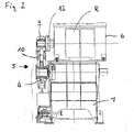
- the pump system 100 includes a pump assembly 1 of conventional design.
- This pump assembly 1 includes a housing 2, from the side facing the viewer one end of a pump drive shaft 3 protrudes. With this shaft end, the output gear 4 of a gear train 5 is rotatably connected.
- the toothed wheel gear 5 is used to produce the operative connection of the pump unit with a rotary drive device 6, which comprises a rotary motor R, which is only indicated in the drawing and is driven, for example, hydraulically or electrically.
- the rotary drive device 6 includes a housing 7 which is flanged to the housing 2 of the pump unit 1 .
- a shaft end of a driven shaft 8 protrudes from the housing 7 of the rotary drive device 6 . It is connected to a drive wheel 9 via a clutch 12, which selectively connects or releases the drive wheel 9 in a rotationally fixed manner to the end of the shaft.
- the drive wheel 9 is coupled to the driven wheel 4 via an intermediate wheel 10 which is rotatably mounted in a housing 11 of the gear train.
- an elastic, non-shiftable clutch can also be provided, which permanently connects the shaft end to the drive wheel.
- the toothing of the intermediate wheel 10 is in mesh with the toothing of the drive wheel 9 and the driven wheel 4.
- the wheels of the gear train are helically toothed to reduce noise.
Landscapes
- Engineering & Computer Science (AREA)
- Mechanical Engineering (AREA)
- General Engineering & Computer Science (AREA)
- Mining & Mineral Resources (AREA)
- Life Sciences & Earth Sciences (AREA)
- Geology (AREA)
- Environmental & Geological Engineering (AREA)
- Fluid Mechanics (AREA)
- Physics & Mathematics (AREA)
- General Life Sciences & Earth Sciences (AREA)
- Geochemistry & Mineralogy (AREA)
- Details And Applications Of Rotary Liquid Pumps (AREA)
- Rotary Pumps (AREA)
- Fluid-Driven Valves (AREA)
- Eye Examination Apparatus (AREA)
- Reciprocating Pumps (AREA)
Claims (2)
- Système de pompe pour un fluide de rinçage (100) avec une unité de pompe (1) et avec juste un dispositif d'entraînement en rotation (6) pour entraîner l'unité de pompe (1) et comprenant un moteur à rotation (R),dans lequel le dispositif d'entraînement en rotation (6) est fonctionnellement relié à l'unité de pompe (1) par l'intermédiaire d'une transmission à engrenage (5) comprenant une roue motrice (9) et une roue de sortie (4), caractérisé en ce que le dispositif d'entraînement en rotation (6) comporte un boîtier (7) à partir duquel une extrémité d'arbre d'un arbre entraîné (8) fait saillie, ladite extrémité étant reliée à la roue motrice (9),dans lequel l'unité de pompe (1) comporte un boîtier (2), à partir duquel une extrémité d'un arbre à entraînement de pompe (3) fait saillie, l'extrémité avec laquelle la roue de sortie (4) de la transmission à engrenage (5) est reliée de manière fixée à rotation, et dans lequel le boîtier (7) du dispositif d'entraînement en rotation (6) est arrangé au-dessus de l'unité de pompe (1) et bridé au côté supérieur du boîtier (2) de l'unité de pompe (1), et dans lequel le dispositif d'entraînement en rotation (6) présente une seule extrémité d'arbre, avec laquelle la roue motrice (9) est reliée de manière rotative,et dans lequel la roue motrice est reliée à l'extrémité d'arbre par un couplage avec lequel une liaison fixée à rotation entre la roue motrice (9) et l'extrémité de l'arbre facultativement peut être réalisée.
- Système de pompe pour un fluide de rinçage selon la revendication 1, caractérisé en ce queles roues dentées (4, 9, 10) sont à denture hélicoïdale.
Applications Claiming Priority (3)
| Application Number | Priority Date | Filing Date | Title |
|---|---|---|---|
| DE102005016884A DE102005016884A1 (de) | 2005-04-12 | 2005-04-12 | Pumpensystem |
| EP06707001.1A EP1869284B1 (fr) | 2005-04-12 | 2006-02-16 | Systeme de pompe |
| PCT/EP2006/001400 WO2006108466A1 (fr) | 2005-04-12 | 2006-02-16 | Systeme de pompe |
Related Parent Applications (3)
| Application Number | Title | Priority Date | Filing Date |
|---|---|---|---|
| EP06707001.1 Division | 2006-02-16 | ||
| EP06707001.1A Division-Into EP1869284B1 (fr) | 2005-04-12 | 2006-02-16 | Systeme de pompe |
| EP06707001.1A Division EP1869284B1 (fr) | 2005-04-12 | 2006-02-16 | Systeme de pompe |
Publications (4)
| Publication Number | Publication Date |
|---|---|
| EP2241752A2 EP2241752A2 (fr) | 2010-10-20 |
| EP2241752A3 EP2241752A3 (fr) | 2015-12-09 |
| EP2241752B1 EP2241752B1 (fr) | 2019-06-12 |
| EP2241752B2 true EP2241752B2 (fr) | 2022-07-20 |
Family
ID=36354140
Family Applications (2)
| Application Number | Title | Priority Date | Filing Date |
|---|---|---|---|
| EP10170292.6A Ceased EP2241752B2 (fr) | 2005-04-12 | 2006-02-16 | Système de pompe |
| EP06707001.1A Revoked EP1869284B1 (fr) | 2005-04-12 | 2006-02-16 | Systeme de pompe |
Family Applications After (1)
| Application Number | Title | Priority Date | Filing Date |
|---|---|---|---|
| EP06707001.1A Revoked EP1869284B1 (fr) | 2005-04-12 | 2006-02-16 | Systeme de pompe |
Country Status (7)
| Country | Link |
|---|---|
| US (1) | US8186977B2 (fr) |
| EP (2) | EP2241752B2 (fr) |
| CN (1) | CN101160446B (fr) |
| DE (1) | DE102005016884A1 (fr) |
| NO (1) | NO343827B1 (fr) |
| RU (1) | RU2392414C2 (fr) |
| WO (1) | WO2006108466A1 (fr) |
Families Citing this family (4)
| Publication number | Priority date | Publication date | Assignee | Title |
|---|---|---|---|---|
| US8920146B2 (en) * | 2005-04-12 | 2014-12-30 | Mhwirth Gmbh | Pump system |
| EP2362116B1 (fr) * | 2010-02-18 | 2017-02-01 | Grundfos Management A/S | Roue dentée ainsi qu'agrégat de pompe doté d'une telle roue dentée |
| JP5934543B2 (ja) * | 2012-03-29 | 2016-06-15 | Kyb株式会社 | 流体圧駆動ユニット |
| GB2585681B (en) | 2019-07-11 | 2022-04-06 | Mhwirth As | Drilling rig systems |
Citations (1)
| Publication number | Priority date | Publication date | Assignee | Title |
|---|---|---|---|---|
| US20040219042A1 (en) † | 2003-04-30 | 2004-11-04 | Vladimir Kugelev | Manifold assembly for reciprocating pump |
Family Cites Families (20)
| Publication number | Priority date | Publication date | Assignee | Title |
|---|---|---|---|---|
| US2899247A (en) * | 1959-08-11 | Feed water pump | ||
| US879560A (en) * | 1905-10-05 | 1908-02-18 | Daniel F Lepley | Triplex pump. |
| US2131749A (en) * | 1936-06-29 | 1938-10-04 | Homestead Valve Mfg Co | Pump |
| US2331513A (en) * | 1937-12-18 | 1943-10-12 | Emsco Derrick & Equip Co | Slush pump |
| US2755739A (en) * | 1953-07-20 | 1956-07-24 | Lever Brothers Ltd | Proportioning pump |
| US2883874A (en) * | 1958-02-03 | 1959-04-28 | Halliburton Oil Well Cementing | Heavy duty pump |
| GB1034058A (en) * | 1964-05-21 | 1966-06-29 | William Stewart Robinson | Improvements in sun-and-planet gearing |
| US4118151A (en) * | 1974-04-03 | 1978-10-03 | Tokico Ltd. | Pump device |
| US4009971A (en) * | 1974-06-07 | 1977-03-01 | Binks Manufacturing Company | Electric motor-driven, double-acting pump having pressure-responsive actuation |
| US4435990A (en) * | 1980-09-11 | 1984-03-13 | Chalmers Samuel A | Power take off gear box |
| CA1205327A (fr) * | 1981-12-04 | 1986-06-03 | Gordon M. Sommer | Entrainement pour pompe sur forage |
| US5246355A (en) | 1992-07-10 | 1993-09-21 | Special Projects Manufacturing, Inc. | Well service pumping assembly |
| RU5224U1 (ru) * | 1997-02-26 | 1997-10-16 | Андрей Петрович Донодин | Насосный агрегат |
| RU2146777C1 (ru) * | 1998-08-12 | 2000-03-20 | Валерий Николаевич Петрухин | Насосный агрегат |
| JP2002526718A (ja) | 1998-10-01 | 2002-08-20 | ペック,ジュリアン,クロード | 手動式ポンプ又はコンプレッサ |
| CN2385075Y (zh) * | 1999-08-23 | 2000-06-28 | 石油地球物理勘探局装备制造总厂 | 石油地质勘探钻机用泥浆泵 |
| US6981855B2 (en) * | 2002-09-30 | 2006-01-03 | Sandvik Ab | Drilling rig having a compact compressor/pump assembly |
| CN2612816Y (zh) * | 2003-03-30 | 2004-04-21 | 泰安市水利机械厂 | 高压柱塞泥浆泵 |
| US20040213677A1 (en) * | 2003-04-24 | 2004-10-28 | Matzner Mark D. | Monitoring system for reciprocating pumps |
| US20040219040A1 (en) * | 2003-04-30 | 2004-11-04 | Vladimir Kugelev | Direct drive reciprocating pump |
-
2005
- 2005-04-12 DE DE102005016884A patent/DE102005016884A1/de not_active Ceased
-
2006
- 2006-02-16 WO PCT/EP2006/001400 patent/WO2006108466A1/fr not_active Ceased
- 2006-02-16 US US11/918,310 patent/US8186977B2/en active Active
- 2006-02-16 EP EP10170292.6A patent/EP2241752B2/fr not_active Ceased
- 2006-02-16 RU RU2007141682/03A patent/RU2392414C2/ru active
- 2006-02-16 CN CN2006800120030A patent/CN101160446B/zh active Active
- 2006-02-16 EP EP06707001.1A patent/EP1869284B1/fr not_active Revoked
-
2007
- 2007-10-09 NO NO20075108A patent/NO343827B1/no unknown
Patent Citations (1)
| Publication number | Priority date | Publication date | Assignee | Title |
|---|---|---|---|---|
| US20040219042A1 (en) † | 2003-04-30 | 2004-11-04 | Vladimir Kugelev | Manifold assembly for reciprocating pump |
Also Published As
| Publication number | Publication date |
|---|---|
| EP1869284B1 (fr) | 2018-12-26 |
| EP2241752B1 (fr) | 2019-06-12 |
| US8186977B2 (en) | 2012-05-29 |
| NO343827B1 (no) | 2019-06-17 |
| WO2006108466A1 (fr) | 2006-10-19 |
| NO20075108L (no) | 2007-11-07 |
| EP2241752A3 (fr) | 2015-12-09 |
| EP1869284A1 (fr) | 2007-12-26 |
| DE102005016884A1 (de) | 2006-10-19 |
| EP2241752A2 (fr) | 2010-10-20 |
| RU2392414C2 (ru) | 2010-06-20 |
| CN101160446B (zh) | 2013-07-03 |
| RU2007141682A (ru) | 2009-05-20 |
| CN101160446A (zh) | 2008-04-09 |
| US20090038852A1 (en) | 2009-02-12 |
Similar Documents
| Publication | Publication Date | Title |
|---|---|---|
| EP0866210B1 (fr) | Méthode d'actionnement d'un outil et dispositif pour la transmission de couple et de vitesse de rotation d'un organe d'entraínement vers cet outil | |
| DE602004010127T2 (de) | Kupplung für doppelwandiges rohr | |
| DE60219033T2 (de) | Spülrohranordnung | |
| DE2047587A1 (de) | Entkupplungsvorrichtung | |
| DE2654197A1 (de) | Fluid-motor-anordnung | |
| DE2162314B2 (de) | Erdbohrmaschine | |
| DE19581945B4 (de) | Antriebskopf für eine Bohrlochpumpe | |
| DE19957791A1 (de) | Hydraulischer Bohrantrieb | |
| DE2229579A1 (de) | Vorrichtung zur Bohrlochmessung während der Bohrung | |
| EP2241752B2 (fr) | Système de pompe | |
| DE2824441C2 (de) | Erdbohrer | |
| DE881484C (de) | Bohrturbine | |
| DE4113986A1 (de) | Hydraulisch angetriebener bohrmotor zum tiefbohren | |
| DE2733199A1 (de) | Bohrvorrichtung zum einbringen von tiefbohrungen in erdreich, gestein u.dgl. | |
| DE102006028347A1 (de) | Drehmomentübertragungsanordnung | |
| DE330888C (de) | Tragbare Antriebsmaschine | |
| DE3024218A1 (de) | Schlag-bohreinrichtung fuer grosslochbohrungen | |
| AU2022200150B2 (en) | Arrangement of a ground drilling device, method for operating a ground drilling device and use of an arrangement of a ground drilling device | |
| DE19617213C1 (de) | Biegestabverbindung | |
| EP4033067B1 (fr) | Agencement d'entraînement rotatif pour une tige de forage | |
| DE102008034083A1 (de) | Erdbohrvorrichtung | |
| EP4606987A1 (fr) | Dispositif pour percer des trous de forage au moyen d'un système de forage | |
| DE389505C (de) | Einrichtung zum Foerdern von Erdoel, Sole und anderen Fluessigkeiten aus Bohrloechern | |
| WO2009156500A1 (fr) | Pompe à piston sans engrenage | |
| DE102013002042A1 (de) | Trennvorrichtung für einen Antriebsstang |
Legal Events
| Date | Code | Title | Description |
|---|---|---|---|
| PUAI | Public reference made under article 153(3) epc to a published international application that has entered the european phase |
Free format text: ORIGINAL CODE: 0009012 |
|
| AC | Divisional application: reference to earlier application |
Ref document number: 1869284 Country of ref document: EP Kind code of ref document: P |
|
| AK | Designated contracting states |
Kind code of ref document: A2 Designated state(s): DE IT |
|
| TPAC | Observations filed by third parties |
Free format text: ORIGINAL CODE: EPIDOSNTIPA |
|
| RAP1 | Party data changed (applicant data changed or rights of an application transferred) |
Owner name: MHWIRTH GMBH |
|
| PUAL | Search report despatched |
Free format text: ORIGINAL CODE: 0009013 |
|
| RIC1 | Information provided on ipc code assigned before grant |
Ipc: E21B 21/08 20060101AFI20151020BHEP |
|
| AK | Designated contracting states |
Kind code of ref document: A3 Designated state(s): DE IT |
|
| TPAC | Observations filed by third parties |
Free format text: ORIGINAL CODE: EPIDOSNTIPA |
|
| 17P | Request for examination filed |
Effective date: 20160607 |
|
| RBV | Designated contracting states (corrected) |
Designated state(s): DE IT |
|
| 17Q | First examination report despatched |
Effective date: 20160914 |
|
| STAA | Information on the status of an ep patent application or granted ep patent |
Free format text: STATUS: EXAMINATION IS IN PROGRESS |
|
| TPAC | Observations filed by third parties |
Free format text: ORIGINAL CODE: EPIDOSNTIPA |
|
| TPAC | Observations filed by third parties |
Free format text: ORIGINAL CODE: EPIDOSNTIPA |
|
| GRAP | Despatch of communication of intention to grant a patent |
Free format text: ORIGINAL CODE: EPIDOSNIGR1 |
|
| STAA | Information on the status of an ep patent application or granted ep patent |
Free format text: STATUS: GRANT OF PATENT IS INTENDED |
|
| INTG | Intention to grant announced |
Effective date: 20190104 |
|
| GRAS | Grant fee paid |
Free format text: ORIGINAL CODE: EPIDOSNIGR3 |
|
| GRAA | (expected) grant |
Free format text: ORIGINAL CODE: 0009210 |
|
| STAA | Information on the status of an ep patent application or granted ep patent |
Free format text: STATUS: THE PATENT HAS BEEN GRANTED |
|
| AC | Divisional application: reference to earlier application |
Ref document number: 1869284 Country of ref document: EP Kind code of ref document: P |
|
| AK | Designated contracting states |
Kind code of ref document: B1 Designated state(s): DE IT |
|
| REG | Reference to a national code |
Ref country code: DE Ref legal event code: R096 Ref document number: 502006016271 Country of ref document: DE |
|
| REG | Reference to a national code |
Ref country code: DE Ref legal event code: R026 Ref document number: 502006016271 Country of ref document: DE |
|
| PLBI | Opposition filed |
Free format text: ORIGINAL CODE: 0009260 |
|
| PLAX | Notice of opposition and request to file observation + time limit sent |
Free format text: ORIGINAL CODE: EPIDOSNOBS2 |
|
| 26 | Opposition filed |
Opponent name: BENTEC GMBH DRILLING & OILFIELD SYSTEMS Effective date: 20200310 |
|
| PLBB | Reply of patent proprietor to notice(s) of opposition received |
Free format text: ORIGINAL CODE: EPIDOSNOBS3 |
|
| RIC2 | Information provided on ipc code assigned after grant |
Ipc: F04C 15/00 20060101ALI20210818BHEP Ipc: F04B 9/02 20060101ALI20210818BHEP Ipc: F01C 21/00 20060101ALI20210818BHEP Ipc: E21B 21/08 20060101AFI20210818BHEP |
|
| PUAH | Patent maintained in amended form |
Free format text: ORIGINAL CODE: 0009272 |
|
| STAA | Information on the status of an ep patent application or granted ep patent |
Free format text: STATUS: PATENT MAINTAINED AS AMENDED |
|
| 27A | Patent maintained in amended form |
Effective date: 20220720 |
|
| AK | Designated contracting states |
Kind code of ref document: B2 Designated state(s): DE IT |
|
| REG | Reference to a national code |
Ref country code: DE Ref legal event code: R102 Ref document number: 502006016271 Country of ref document: DE |
|
| PGFP | Annual fee paid to national office [announced via postgrant information from national office to epo] |
Ref country code: IT Payment date: 20230103 Year of fee payment: 18 Ref country code: DE Payment date: 20230104 Year of fee payment: 18 |
|
| REG | Reference to a national code |
Ref country code: DE Ref legal event code: R119 Ref document number: 502006016271 Country of ref document: DE |
|
| PG25 | Lapsed in a contracting state [announced via postgrant information from national office to epo] |
Ref country code: DE Free format text: LAPSE BECAUSE OF NON-PAYMENT OF DUE FEES Effective date: 20240903 |
|
| PG25 | Lapsed in a contracting state [announced via postgrant information from national office to epo] |
Ref country code: DE Free format text: LAPSE BECAUSE OF NON-PAYMENT OF DUE FEES Effective date: 20240903 |
|
| PG25 | Lapsed in a contracting state [announced via postgrant information from national office to epo] |
Ref country code: IT Free format text: LAPSE BECAUSE OF NON-PAYMENT OF DUE FEES Effective date: 20240216 |