EP2241718A1 - Star engine - Google Patents
Star engine Download PDFInfo
- Publication number
- EP2241718A1 EP2241718A1 EP09005356A EP09005356A EP2241718A1 EP 2241718 A1 EP2241718 A1 EP 2241718A1 EP 09005356 A EP09005356 A EP 09005356A EP 09005356 A EP09005356 A EP 09005356A EP 2241718 A1 EP2241718 A1 EP 2241718A1
- Authority
- EP
- European Patent Office
- Prior art keywords
- rotor
- engine
- housing
- eccentric shaft
- star
- Prior art date
- Legal status (The legal status is an assumption and is not a legal conclusion. Google has not performed a legal analysis and makes no representation as to the accuracy of the status listed.)
- Withdrawn
Links
Images


Classifications
-
- F—MECHANICAL ENGINEERING; LIGHTING; HEATING; WEAPONS; BLASTING
- F01—MACHINES OR ENGINES IN GENERAL; ENGINE PLANTS IN GENERAL; STEAM ENGINES
- F01C—ROTARY-PISTON OR OSCILLATING-PISTON MACHINES OR ENGINES
- F01C1/00—Rotary-piston machines or engines
- F01C1/08—Rotary-piston machines or engines of intermeshing engagement type, i.e. with engagement of co- operating members similar to that of toothed gearing
- F01C1/10—Rotary-piston machines or engines of intermeshing engagement type, i.e. with engagement of co- operating members similar to that of toothed gearing of internal-axis type with the outer member having more teeth or tooth-equivalents, e.g. rollers, than the inner member
- F01C1/104—Rotary-piston machines or engines of intermeshing engagement type, i.e. with engagement of co- operating members similar to that of toothed gearing of internal-axis type with the outer member having more teeth or tooth-equivalents, e.g. rollers, than the inner member one member having simultaneously a rotational movement about its own axis and an orbital movement
-
- F—MECHANICAL ENGINEERING; LIGHTING; HEATING; WEAPONS; BLASTING
- F01—MACHINES OR ENGINES IN GENERAL; ENGINE PLANTS IN GENERAL; STEAM ENGINES
- F01C—ROTARY-PISTON OR OSCILLATING-PISTON MACHINES OR ENGINES
- F01C17/00—Arrangements for drive of co-operating members, e.g. for rotary piston and casing
- F01C17/02—Arrangements for drive of co-operating members, e.g. for rotary piston and casing of toothed-gearing type
-
- F—MECHANICAL ENGINEERING; LIGHTING; HEATING; WEAPONS; BLASTING
- F01—MACHINES OR ENGINES IN GENERAL; ENGINE PLANTS IN GENERAL; STEAM ENGINES
- F01C—ROTARY-PISTON OR OSCILLATING-PISTON MACHINES OR ENGINES
- F01C21/00—Component parts, details or accessories not provided for in groups F01C1/00 - F01C20/00
- F01C21/008—Driving elements, brakes, couplings, transmissions specially adapted for rotary or oscillating-piston machines or engines
Definitions
- the intake stroke starts when both the rotor and stator are completely closed (follow the dot on the end of the rotor).
- the eccentric shaft starts to revolve clockwise, it forces the rotor to roll counter-clockwise and the gap between rotor and stator is open (or vice-versa). This situation forms low-pressure with a vacuum-like effect inside the combustion chamber. A mixture of fuel and air is then drawn into the combustion chamber when the intake valve opens.
- Both the intake and exhaust valves are closed by the end of the intake stroke. This means that the mixture of fuel and air is "trapped" inside the combustion chamber. As the rotor continues to roll, the gap between the rotor and the stator is closed, and the mixture is compressed.
- a spark is provided inside the combustion chamber near the end of the compression stroke, which causes the mixture of fuel and air to explode. This explosion forces the gap between rotor and stator to open again.
- the explosion stroke is the single source of power to manipulate the engine.
- a Star 651 water-cool with twin rotors in FIGURE 8 is used as an example.
- stator The large circle is cut along the path of the rotor to a six-pointed star called a stator, which is the housing for the rotor (1 & 5).
- the stator has a built-in rotor wall on the inner part of the stator (7) which is chrome-plated on the inner faces to prevent wearing.
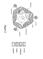
- the stator is housing for three spark plugs and is divided into three complete valve train systems. ( FIGURE 3 )
- the water-cool stator is casted by a light but strong material such as aluminum, and is thin-walled (water pocketing) for the cooling liquid such as water to run through inside using a pump.
- the heated water then passes through a radiator (not shown) for cooling and reusing.
- the stator is grooved on both sides, and is sealed with a pair of outer and inner gaskets (8 & 9).
- the rotor is housed on the front side by a front rotor cover (2).
- This part is cast-iron, which is heat-treated and hardened on side that houses the rotor.
- This part is water pocketed for cooling.
- This part also houses the planetary gearset ( FIGURE 11 ), the oil pump ( FIGURE 17 ), the alternator ( FIGURE 18 ), the thermostat, the water pump ( FIGURE 19 )
- the intermediate rotor cover (4) In the middle of the front and the rear rotors is the intermediate rotor cover (4). In the top portion below the top camshaft holder is a built-in intake air tunnel that draws air from the air inlet on the left side to the right side of the engine. This part is thin-walled for cooling, and at the center of this part is a large through hole that houses the eccentric shaft. This part is heat-treated and hardened on both sides to house the front and rear rotors.
- the rear end of the rear rotor is also housed by a rear rotor cover (6).
- This part is also thin-walled for water cooling.
- This part is cast-iron, and is also heat-treated and hardened on the side where it houses the rotor. In the center of the part there is a hole that houses for the planetary gearset.
- the small circle in the shape of a five-pointed star called a rotor, which rolls inside its rotor housing (11a & 11b).
- the rotor has built-in combustion chambers hollowed on all of its lowest faces (12).
- the rotor is grooved on the front and the back for sealing, and each peak is also grooved for apex seals (20 & 21).
- the rotor is the main part that creates power for the output.
- the rotor revolves the main shaft eccentrically to convert the eccentric turning of the rotor to a circular turning on the output.
- This output shaft is called the eccentric shaft (24), which is mounted with a planetary gearset in the central axis of the engine, which is also the center of the stator.
- the planetary gearset ( FIGURE 10 & 11 ) is a mechanism device used to converse the eccentric motion of the rotor to the rotary motion of the eccentric shaft, meshing the rotor to revolve on its own path without touching the rotor wall, setting the alignment of the rotor and eccentric shaft, and securing the endplay of the shaft.
- the planetary gearset comes with a ring gear (15) which is fixed to one end of the eccentric shaft using an eccentric shaft weight, (24) which rotates the sun gear (16) in the opposite direction over three neutral gears (17).
- the neutral gears are arranged and mounted on the planetary gearset housing (14) in equal spaces.
- the other end of the sun gear is meshed onto the rotor ring gear (13) in the front of the rotor, forcing the rotor to roll in a fixed journey inside its housing.
- Star Engine 651 is equipped with three valve train systems ( FIGURE 12 & 13 ).
- the camshafts are arranged in even spaces: the top camshaft (27), the left camshaft (28), and the right camshaft (29).
- These camshafts are attached with the cam chain sprockets (30, 31, & 32) on the front ends, and are linked to the eccentric shaft chain sprocket (25), which is then driven by the eccentric shaft using a timing chain (26).
- the chain is also linked an oil pump sprocket (33) and a chain tensioner (not shown).
- Each camshaft has three bearing journals mounted on the camshaft holder of the front, intermediate and rear rotor covers.
- the front camshaft journal is fitted with two semi-circular bearings.
- the lower front bearing (35) is placed on the front rotor cover camshaft holder.
- the upper front bearing (34) is placed on top and secured the front camshaft holder (31).
- the pair of front bearings in the design is also used to secure the endplay of the camshaft.
- the intermediate journal is fitted with the middle upper bearing (36), the middle lower bearing (37), and the middle camshaft holder (32).
- the rear journal is fitted with a set of parts (33, 38, & 39) similar to the middle one.
- the air taken in Before entering a combustions chamber, the air taken in must be free of dirt by going through an air filter (not shown). The amount of air is controlled by a throttle plate when going through the throttle body (58) to the right (58) and left (59) intake manifolds. The exhaust gasses are blown out through these exhaust manifolds (58 & 61) ( FIGURE 14 ).
- Star Engine is covered with a top, left, and right valve covers (65, 66, & 67), which are sealed with gaskets (68, 69, & 70) ( FIGURE 15 ).
- gaskets 68, 69, & 70
- FIGURE 15 At the bottom of the engine is an oil pan (72) ( FIGURE 16 ).
- the lubrication system ( FIGURE 17 ) lubricates the engine with an oil pump driven by the eccentric shaft through the timing chain.
- the oil pump is of rotor type (77 - 89) mounted on the lower part under the planetary gearset housing of the front rotor cover. Oil is sucked through the oil screen (100) over the oil strainer (99) to the oil filter (104), which is then split by an oil branch (93). The oil then comes to the front planetary gearset, to the eccentric shaft through eccentric shaft oil passages, to the oil jet nozzles and finally to the rear planetary gearset. Oil also comes to the camshafts and their bearings through oil lines (95 & 96).
- the electrical system comes with an alternator (109) mounted on the front rotor cover (2) and is driven the eccentric shaft (24) using a belt (106) and pulley (105).
- the belt tension can be adjusted by a belt tensioner (111), which is mounted on a tensioner bracket (114) and an adjustable tensioner bar (113) ( FIGURE 18 ).
- the cooling system ( FIGURE 19 ) is used to maintain a normal, operational temperature for the engine to work in.
- the water pump is located above of the eccentric shaft and on the left front side of the front rotor cover.
- the water pump is driven by the eccentric shaft by a belt (106).
- the pump shaft (127) is centered inside the pump body (125) and mounted with the ball bearings (122 & 123) and sealed by a seal (124).
- a main object of the invention is to make the most of fuel energy by minimizing the loss of power during engine operation, therefore leaving more power for the output.
- a further object of the invention is to reduce the use of material and maintain a light weight, the engine being compact in design.
- a still further object of the invention is to minimize the loss of power by directly transferring power from the rotor to the output shaft.
- a still further object of the invention is to reduce the friction force between the turning parts by shortening the traveling distance of the rotor, additionally reducing power consumption.
- a still further object of the invention is to have a slower and smoother operation, allowing more time for the fuel to burn completely and creating higher fuel efficiency.
Abstract
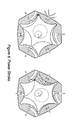
Star Engine is a four stroke internal combustion engine, which converts the eccentric motion of the center of the rotor directly to a rotary motion of a main shaft. This engine is formed by the principle a small circle rolling inside a larger one (FIGURE 1 ). The star shape of both the rotor and stator are formed by the ratio between them (FIGURE 2 ).
Description
-
- 1. The Star Engine is based on the principle:
- WHEN A CIRCLE ROLLS INSIDE A LARGER ONE, ITS MOVEMENT IS DETERMINED BY THE RATIO BETWEEN THEM.
- 2. The movement of any point on the small circle is determined by the trigonometric equation:

Where r is the path of a point on the World Coordinate System, cos θ is the eccentric diameter of the eccentric shaft in degree (r = cos θ is equation of a circle), n is a distance other than 0 (values either being positive or negative) or the radius of the eccentric diameter of the central point, and cos α is the ratio of the difference of the two circles in size, also in degree. For example: the difference of the two circles of the Star Engine 651 is 5 to 1 in degree.
When θ = 30° , α = 6° , and when θ = 60° , α - 12° , and so forth. - 3. The position of x and y of any point on the World Coordinate System can be found by these equations:


-
- 1. Depending on the sizes between the two circles, this ratio can vary, meaning the types of Star Engine may also vary:
- The ratio of 3:4 creates a Star Engine Type 431, which the rotor is a three-pointed star and the stator is a four-pointed star. This engine comes with two spark plugs and two sets of valve trains.
- The ratio of 5:6 creates a Star Engine Type 651, which the rotor is a five-pointed star and the stator is a six-pointed star. This engine comes with three spark plugs and three sets of valve trains.
- The ratio of 7:8 creates a Star Engine Type 871, which the rotor is a seven-pointed star and the stator is an eight-pointed star. This engine comes with four spark plugs and four sets of valve trains.
- 2. This ratio can be added up, and the small number is always the rotor
- 3. The number of rotors in an engine can vary, being single, double, triple, quadruple, etc
- 4. Star Engine is created by applying the principle of a small circle rolling inside a larger one (
FIGURE 1 ). Star Engine is built by taking advantage the eccentric turning of the small circle' s center point, as well as the movement of a contacting point between the two circles (FIGURE 2 ), the increasing and decreasing of gaps between the rotor (small circle) rolling inside the stator (large one) (FIGURE 3 ), and the ability to mathematically calculate the movement and journey of the small circle (Figure 21 ). - 5. Star Engine is a four stroke internal combustion engine, where fuel is burnt inside to produce power. The four strokes are: intake, compress, power, and exhaust.
- The intake stroke starts when both the rotor and stator are completely closed (follow the dot on the end of the rotor). When the eccentric shaft starts to revolve clockwise, it forces the rotor to roll counter-clockwise and the gap between rotor and stator is open (or vice-versa). This situation forms low-pressure with a vacuum-like effect inside the combustion chamber. A mixture of fuel and air is then drawn into the combustion chamber when the intake valve opens.
- Both the intake and exhaust valves are closed by the end of the intake stroke. This means that the mixture of fuel and air is "trapped" inside the combustion chamber. As the rotor continues to roll, the gap between the rotor and the stator is closed, and the mixture is compressed.
- A spark is provided inside the combustion chamber near the end of the compression stroke, which causes the mixture of fuel and air to explode. This explosion forces the gap between rotor and stator to open again. The explosion stroke is the single source of power to manipulate the engine.
- After the mixture of fuel and air is ignited, combusted, and completely burned, it needs to be forced out and replaced with a fresh mixture for the next cycle. As the gap between the rotor and stator begins to close again, the exhaust valve opens and the burned gases are pushed out. A new cycle is then started.
- From the above opportunity, many variations of the engine may be built. A Star 651 water-cool with twin rotors in
FIGURE 8 is used as an example. - The large circle is cut along the path of the rotor to a six-pointed star called a stator, which is the housing for the rotor (1 & 5).The stator has a built-in rotor wall on the inner part of the stator (7) which is chrome-plated on the inner faces to prevent wearing. The stator is housing for three spark plugs and is divided into three complete valve train systems. (
FIGURE 3 ) - The water-cool stator is casted by a light but strong material such as aluminum, and is thin-walled (water pocketing) for the cooling liquid such as water to run through inside using a pump. The heated water then passes through a radiator (not shown) for cooling and reusing. The stator is grooved on both sides, and is sealed with a pair of outer and inner gaskets (8 & 9).
- The rotor is housed on the front side by a front rotor cover (2). This part is cast-iron, which is heat-treated and hardened on side that houses the rotor. This part is water pocketed for cooling. This part also houses the planetary gearset (
FIGURE 11 ), the oil pump (FIGURE 17 ), the alternator (FIGURE 18 ), the thermostat, the water pump (FIGURE 19 ) - In the middle of the front and the rear rotors is the intermediate rotor cover (4). In the top portion below the top camshaft holder is a built-in intake air tunnel that draws air from the air inlet on the left side to the right side of the engine. This part is thin-walled for cooling, and at the center of this part is a large through hole that houses the eccentric shaft. This part is heat-treated and hardened on both sides to house the front and rear rotors.
- The rear end of the rear rotor is also housed by a rear rotor cover (6).This part is also thin-walled for water cooling. This part is cast-iron, and is also heat-treated and hardened on the side where it houses the rotor. In the center of the part there is a hole that houses for the planetary gearset.
- The small circle in the shape of a five-pointed star called a rotor, which rolls inside its rotor housing (11a & 11b). The rotor has built-in combustion chambers hollowed on all of its lowest faces (12). The rotor is grooved on the front and the back for sealing, and each peak is also grooved for apex seals (20 & 21). The rotor is the main part that creates power for the output.
- The rotor revolves the main shaft eccentrically to convert the eccentric turning of the rotor to a circular turning on the output. This output shaft is called the eccentric shaft (24), which is mounted with a planetary gearset in the central axis of the engine, which is also the center of the stator.
- The planetary gearset (
FIGURE 10 &11 ) is a mechanism device used to converse the eccentric motion of the rotor to the rotary motion of the eccentric shaft, meshing the rotor to revolve on its own path without touching the rotor wall, setting the alignment of the rotor and eccentric shaft, and securing the endplay of the shaft. - The planetary gearset comes with a ring gear (15) which is fixed to one end of the eccentric shaft using an eccentric shaft weight, (24) which rotates the sun gear (16) in the opposite direction over three neutral gears (17). The neutral gears are arranged and mounted on the planetary gearset housing (14) in equal spaces. The other end of the sun gear is meshed onto the rotor ring gear (13) in the front of the rotor, forcing the rotor to roll in a fixed journey inside its housing.
- Star Engine 651 is equipped with three valve train systems (
FIGURE 12 &13 ). The camshafts are arranged in even spaces: the top camshaft (27), the left camshaft (28), and the right camshaft (29). These camshafts are attached with the cam chain sprockets (30, 31, & 32) on the front ends, and are linked to the eccentric shaft chain sprocket (25), which is then driven by the eccentric shaft using a timing chain (26). The chain is also linked an oil pump sprocket (33) and a chain tensioner (not shown). - Each camshaft has three bearing journals mounted on the camshaft holder of the front, intermediate and rear rotor covers. The front camshaft journal is fitted with two semi-circular bearings. The lower front bearing (35) is placed on the front rotor cover camshaft holder. The upper front bearing (34) is placed on top and secured the front camshaft holder (31). The pair of front bearings in the design is also used to secure the endplay of the camshaft. The intermediate journal is fitted with the middle upper bearing (36), the middle lower bearing (37), and the middle camshaft holder (32). The rear journal is fitted with a set of parts (33, 38, & 39) similar to the middle one.
- The rotation of a camshaft converts its rotary motion to a reciprocating motion of the intake and exhaust valves (57). Star Engine is equipped with a removable valve train set (
FIGURE 13 ): As the camshaft is turning, its lobes push the tappets (49) on top of the valves down and up to open and closed the combustion chambers, therefore letting the burnt gasses out and taking in a fresh mixture of fuel and air. - Before entering a combustions chamber, the air taken in must be free of dirt by going through an air filter (not shown). The amount of air is controlled by a throttle plate when going through the throttle body (58) to the right (58) and left (59) intake manifolds. The exhaust gasses are blown out through these exhaust manifolds (58 & 61) (
FIGURE 14 ). - Star Engine is covered with a top, left, and right valve covers (65, 66, & 67), which are sealed with gaskets (68, 69, & 70) (
FIGURE 15 ). At the bottom of the engine is an oil pan (72) (FIGURE 16 ). - The lubrication system (
FIGURE 17 ) lubricates the engine with an oil pump driven by the eccentric shaft through the timing chain. The oil pump is of rotor type (77 - 89) mounted on the lower part under the planetary gearset housing of the front rotor cover. Oil is sucked through the oil screen (100) over the oil strainer (99) to the oil filter (104), which is then split by an oil branch (93). The oil then comes to the front planetary gearset, to the eccentric shaft through eccentric shaft oil passages, to the oil jet nozzles and finally to the rear planetary gearset. Oil also comes to the camshafts and their bearings through oil lines (95 & 96). - The electrical system (
FIGURE 18 ) comes with an alternator (109) mounted on the front rotor cover (2) and is driven the eccentric shaft (24) using a belt (106) and pulley (105).The belt tension can be adjusted by a belt tensioner (111), which is mounted on a tensioner bracket (114) and an adjustable tensioner bar (113) (FIGURE 18 ). - The cooling system (
FIGURE 19 ) is used to maintain a normal, operational temperature for the engine to work in. There only some parts that attached to the engine are shown such as the water pump and the water outlet and their related components. The water pump is located above of the eccentric shaft and on the left front side of the front rotor cover. The water pump is driven by the eccentric shaft by a belt (106). The pump shaft (127) is centered inside the pump body (125) and mounted with the ball bearings (122 & 123) and sealed by a seal (124). -
-
FIGURE 1 is a sketch of five different positions of the small circle rolling inside a larger one. -
FIGURE 2 is a sketch showing the basics of the invention on a ratio of 5 and 6 between the two circles. -
FIGURE 3 is a perspective view of Star Engine showing four strokes going on inside the engine. -
FIGURE 4 is showing stroke one, the intake stroke. -
FIGURE 5 is showing stroke two, the compress stroke. -
FIGURE 6 is showing stroke three, the power stroke. -
FIGURE 7 is showing stroke four, the exhaust stroke. -
FIGURE 8 is a perspective view of Star Engine with a combination of assembly, cutaway, and exploded views showing inside and outside the engine. -
FIGURE 9 is an explode view showing the stators and its related parts. -
FIGURE 10 is a perspective view of Star Engine with a combination of assembly, section, and exploded views showing the rotor, eccentric shaft, and a planetary gearset. -
FIGURE 11 is an exploded view of the planetary gearset. -
FIGURE 12 is a perspective view of the eccentric shaft, camshafts, oil pump chain sprocket, cam chain sprockets, and a chain. -
FIGURE 13 is an exploded view of a camshaft and its related components, and an exploded view of a removable valve train. -
FIGURE 14 is an exploded view of the air intake and exhaust system components. -
FIGURE 15 is an exploded view of the valve covers and gaskets. -
FIGURE 16 is an exploded view of an oil pan and its related components. -
FIGURE 17 is an exploded view of lubrication components. -
FIGURE 18 is an exploded view of an alternator and its related components. -
FIGURE 19 is an exploded view of a water pump and its related components. -
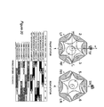
FIGURE 20 is a perspective view of the front and the rear stator, and the firing order of the engine. -
FIGURE 21 is a graph of the paths of the points on the World Coordinate System and tables of some sample values. - A main object of the invention is to make the most of fuel energy by minimizing the loss of power during engine operation, therefore leaving more power for the output.
- A further object of the invention is to reduce the use of material and maintain a light weight, the engine being compact in design.
- A still further object of the invention is to minimize the loss of power by directly transferring power from the rotor to the output shaft.
- A still further object of the invention is to reduce the friction force between the turning parts by shortening the traveling distance of the rotor, additionally reducing power consumption.
- A still further object of the invention is to have a slower and smoother operation, allowing more time for the fuel to burn completely and creating higher fuel efficiency.
Claims (15)
- A star engine comprising:At least one stator housing for a rotor;At least one rotor driven by an eccentric shaft;An eccentric shaft rotating about its own central axis anddriving the rotor(s) eccentrically;A front rotor cover mounted on the front end of the stator housing for the front end of the rotor;A rear rotor cover mounted the back side of the stator housing for the rear end of the rotor;An intermediate rotor cover attached to the front and rear stator housing for the rotors if twin rotors are used;A ring gear fixed on the front of the eccentric shaft via a balance weight;A ring gear fixed on the front of the rotor;At least one camshaft mounted on top of the intake andexhaust valves;At least one set of removable intake and exhaust valves operated by a camshaft mounted on top;At least one set of fixed planetary gearset mounted on the center of the front end of the front rotor cover;
- The star engine of claim 1 wherein the stator has rotor housing curves formed by the trigonometric equation r = cos θ + n cos α ;
- The star engine of claim 2 wherein the stator has an even number of curved sides (lobes) on the inner part housing for a rotor;
- The star engine of claim 2 wherein the stator has at least one spark plug housing on every two lobes;
- The star engine of claim 2 wherein a set of intake and exhaust valves housing is present on every two lobes (curved sides) starting next to the spark plug housing;
- The star engine of claim 1 wherein the rotor has built-in combustion chambers hollowed on all of its lowest faces;
- The star engine of claim 6 wherein it is grooved on the front and the back for sealing;
- The star engine of claim 6 wherein its peaks are grooved for apex seals;
- The star engine of claim 6 wherein its movement is characterized as a small circle rolling inside a larger one and can be determined and calculated by the trigonometric equation r = cos θ + n cos α ;
- The star engine of claim 6 wherein it has an odd number of curved sides which is one side less than the inner sides (rotor housing) of stator;
- The star engine of claim 6 wherein it has a ring gear housing at the front;
- The star engine of claim 6 wherein it is fixed with a ring gear at the front end driven by the sun gear of the planetary gearset;
- The star engine of claim 1 wherein at least one set of planetary gearsets are mounted on the front end of the eccentric shaft, which is the central axis of the engine. Driven by the eccentric shaft, the ring gear rotates the sun gear in the opposite direction over three neutral gears. The neutral gears are equally arranged and mounted on the planetary gearset housing. The other end of the sun gear is meshed onto the rotor ring gear, which is mounted on the front of the rotor;
- The star engine of claim 1 wherein an eccentric shaft is mounted to the center of the front and rear rotor housing covers, which is a main output shaft converting the eccentric turning of the rotor to a circular turning of the output;
- The star engine of claim 14 wherein at least one pair of front and rear eccentric shaft weights are fixed on both ends of the eccentric shaft. The front eccentric shaft weights are mounted with a ring gear driving the sun gear in the opposite direction;
Priority Applications (1)
| Application Number | Priority Date | Filing Date | Title |
|---|---|---|---|
| EP09005356A EP2241718A1 (en) | 2009-04-15 | 2009-04-15 | Star engine |
Applications Claiming Priority (1)
| Application Number | Priority Date | Filing Date | Title |
|---|---|---|---|
| EP09005356A EP2241718A1 (en) | 2009-04-15 | 2009-04-15 | Star engine |
Publications (1)
| Publication Number | Publication Date |
|---|---|
| EP2241718A1 true EP2241718A1 (en) | 2010-10-20 |
Family
ID=41328977
Family Applications (1)
| Application Number | Title | Priority Date | Filing Date |
|---|---|---|---|
| EP09005356A Withdrawn EP2241718A1 (en) | 2009-04-15 | 2009-04-15 | Star engine |
Country Status (1)
| Country | Link |
|---|---|
| EP (1) | EP2241718A1 (en) |
Citations (8)
| Publication number | Priority date | Publication date | Assignee | Title |
|---|---|---|---|---|
| DE414993C (en) * | 1924-01-22 | 1925-06-18 | Bbc Brown Boveri & Cie | Internal combustion engine in the manner of a gear pump |
| US3208666A (en) * | 1963-01-14 | 1965-09-28 | Beteiligungs & Patentverw Gmbh | Circular piston engine |
| DE1551089A1 (en) * | 1966-04-09 | 1970-01-29 | Dornier System Gmbh | Rotary piston machine, in particular rotary piston internal combustion engine with a trochoid-shaped piston runner mounted on an eccentric shaft and a surrounding body parallel to it |
| GB1350728A (en) * | 1972-06-15 | 1974-04-24 | Dornier System Gmbh | Trochoid-type rotary piston machine |
| US3888606A (en) * | 1973-12-26 | 1975-06-10 | Ford Motor Co | Rotary internal combustion engine |
| US3913533A (en) * | 1973-06-14 | 1975-10-21 | James B Meaden | Rotary internal combustion engine |
| DE2604816A1 (en) * | 1976-02-07 | 1977-08-11 | Traugott Horsch | Multi lobe piston rotary IC engine - has curved piston sides and rotating disc instead of valves |
| WO1991014081A1 (en) * | 1990-03-14 | 1991-09-19 | Scalzo Automotive Research Ltd. | Engine stabiliser mechanism |
-
2009
- 2009-04-15 EP EP09005356A patent/EP2241718A1/en not_active Withdrawn
Patent Citations (8)
| Publication number | Priority date | Publication date | Assignee | Title |
|---|---|---|---|---|
| DE414993C (en) * | 1924-01-22 | 1925-06-18 | Bbc Brown Boveri & Cie | Internal combustion engine in the manner of a gear pump |
| US3208666A (en) * | 1963-01-14 | 1965-09-28 | Beteiligungs & Patentverw Gmbh | Circular piston engine |
| DE1551089A1 (en) * | 1966-04-09 | 1970-01-29 | Dornier System Gmbh | Rotary piston machine, in particular rotary piston internal combustion engine with a trochoid-shaped piston runner mounted on an eccentric shaft and a surrounding body parallel to it |
| GB1350728A (en) * | 1972-06-15 | 1974-04-24 | Dornier System Gmbh | Trochoid-type rotary piston machine |
| US3913533A (en) * | 1973-06-14 | 1975-10-21 | James B Meaden | Rotary internal combustion engine |
| US3888606A (en) * | 1973-12-26 | 1975-06-10 | Ford Motor Co | Rotary internal combustion engine |
| DE2604816A1 (en) * | 1976-02-07 | 1977-08-11 | Traugott Horsch | Multi lobe piston rotary IC engine - has curved piston sides and rotating disc instead of valves |
| WO1991014081A1 (en) * | 1990-03-14 | 1991-09-19 | Scalzo Automotive Research Ltd. | Engine stabiliser mechanism |
Similar Documents
| Publication | Publication Date | Title |
|---|---|---|
| US20050229876A1 (en) | Two-way cylinder engine | |
| CN101365869B (en) | Rotary combustion apparatus | |
| KR20040031074A (en) | Reciprocating piston engine comprising a rotative cylinder | |
| US10184392B2 (en) | Single chamber multiple independent contour rotary machine | |
| US3724427A (en) | Rotary internal combustion engine | |
| US4170978A (en) | Rotary engine | |
| US4099448A (en) | Oscillating engine | |
| US6615793B1 (en) | Valveless revolving cylinder engine | |
| CN100594294C (en) | Reciprocating and rotary internal combustion engine, compressor and pump | |
| RU2619672C1 (en) | Six-stroke rotary-vane internal combustion engine | |
| US20100132658A1 (en) | Star engine | |
| EP2241718A1 (en) | Star engine | |
| CA2634628C (en) | Star engine | |
| US20070119408A1 (en) | Rotary machine with major and satellite rotors | |
| WO2007054106A1 (en) | Internal combustion rotary orbital engine | |
| RU2418180C1 (en) | Rotary engine and cam shaft | |
| US11466614B2 (en) | Rotary roller motor | |
| RU2415285C2 (en) | Rotary engine | |
| PL216801B1 (en) | Multicylinder engine, particularly for compressed gases, or internal combustion engine with variable compression ratio | |
| RU2272164C2 (en) | Rotary internal combustion engine | |
| RU2602938C1 (en) | Rotary internal combustion engine | |
| RU2091596C1 (en) | Rotary-piston internal combustion entire | |
| RU82770U1 (en) | ROTOR-PISTON INTERNAL COMBUSTION ENGINE | |
| RU2072433C1 (en) | Rotary-piston internal combustion engine | |
| JPH02252909A (en) | Opposed piston rotary type sleeve valve internal combustion engine |
Legal Events
| Date | Code | Title | Description |
|---|---|---|---|
| PUAI | Public reference made under article 153(3) epc to a published international application that has entered the european phase |
Free format text: ORIGINAL CODE: 0009012 |
|
| AK | Designated contracting states |
Kind code of ref document: A1 Designated state(s): AT BE BG CH CY CZ DE DK EE ES FI FR GB GR HR HU IE IS IT LI LT LU LV MC MK MT NL NO PL PT RO SE SI SK TR |
|
| AX | Request for extension of the european patent |
Extension state: AL BA RS |
|
| STAA | Information on the status of an ep patent application or granted ep patent |
Free format text: STATUS: THE APPLICATION IS DEEMED TO BE WITHDRAWN |
|
| 18D | Application deemed to be withdrawn |
Effective date: 20110421 |