EP2241378A2 - .steuersystem zur beschichtung von dosen - Google Patents
.steuersystem zur beschichtung von dosen Download PDFInfo
- Publication number
- EP2241378A2 EP2241378A2 EP20090013521 EP09013521A EP2241378A2 EP 2241378 A2 EP2241378 A2 EP 2241378A2 EP 20090013521 EP20090013521 EP 20090013521 EP 09013521 A EP09013521 A EP 09013521A EP 2241378 A2 EP2241378 A2 EP 2241378A2
- Authority
- EP
- European Patent Office
- Prior art keywords
- coating
- spray
- gun
- pressure
- signal
- Prior art date
- Legal status (The legal status is an assumption and is not a legal conclusion. Google has not performed a legal analysis and makes no representation as to the accuracy of the status listed.)
- Ceased
Links
Images


Classifications
-
- B—PERFORMING OPERATIONS; TRANSPORTING
- B05—SPRAYING OR ATOMISING IN GENERAL; APPLYING FLUENT MATERIALS TO SURFACES, IN GENERAL
- B05B—SPRAYING APPARATUS; ATOMISING APPARATUS; NOZZLES
- B05B12/00—Arrangements for controlling delivery; Arrangements for controlling the spray area
- B05B12/004—Arrangements for controlling delivery; Arrangements for controlling the spray area comprising sensors for monitoring the delivery, e.g. by displaying the sensed value or generating an alarm
- B05B12/006—Pressure or flow rate sensors
- B05B12/008—Pressure or flow rate sensors integrated in or attached to a discharge apparatus, e.g. a spray gun
-
- B—PERFORMING OPERATIONS; TRANSPORTING
- B05—SPRAYING OR ATOMISING IN GENERAL; APPLYING FLUENT MATERIALS TO SURFACES, IN GENERAL
- B05B—SPRAYING APPARATUS; ATOMISING APPARATUS; NOZZLES
- B05B12/00—Arrangements for controlling delivery; Arrangements for controlling the spray area
- B05B12/02—Arrangements for controlling delivery; Arrangements for controlling the spray area for controlling time, or sequence, of delivery
-
- B—PERFORMING OPERATIONS; TRANSPORTING
- B05—SPRAYING OR ATOMISING IN GENERAL; APPLYING FLUENT MATERIALS TO SURFACES, IN GENERAL
- B05B—SPRAYING APPARATUS; ATOMISING APPARATUS; NOZZLES
- B05B12/00—Arrangements for controlling delivery; Arrangements for controlling the spray area
- B05B12/08—Arrangements for controlling delivery; Arrangements for controlling the spray area responsive to condition of liquid or other fluent material to be discharged, of ambient medium or of target ; responsive to condition of spray devices or of supply means, e.g. pipes, pumps or their drive means
- B05B12/085—Arrangements for controlling delivery; Arrangements for controlling the spray area responsive to condition of liquid or other fluent material to be discharged, of ambient medium or of target ; responsive to condition of spray devices or of supply means, e.g. pipes, pumps or their drive means responsive to flow or pressure of liquid or other fluent material to be discharged
- B05B12/087—Flow or presssure regulators, i.e. non-electric unitary devices comprising a sensing element, e.g. a piston or a membrane, and a controlling element, e.g. a valve
-
- B—PERFORMING OPERATIONS; TRANSPORTING
- B05—SPRAYING OR ATOMISING IN GENERAL; APPLYING FLUENT MATERIALS TO SURFACES, IN GENERAL
- B05B—SPRAYING APPARATUS; ATOMISING APPARATUS; NOZZLES
- B05B13/00—Machines or plants for applying liquids or other fluent materials to surfaces of objects or other work by spraying, not covered by groups B05B1/00 - B05B11/00
- B05B13/02—Means for supporting work; Arrangement or mounting of spray heads; Adaptation or arrangement of means for feeding work
- B05B13/0221—Means for supporting work; Arrangement or mounting of spray heads; Adaptation or arrangement of means for feeding work characterised by the means for moving or conveying the objects or other work, e.g. conveyor belts
- B05B13/0228—Means for supporting work; Arrangement or mounting of spray heads; Adaptation or arrangement of means for feeding work characterised by the means for moving or conveying the objects or other work, e.g. conveyor belts the movement of the objects being rotative
-
- B—PERFORMING OPERATIONS; TRANSPORTING
- B05—SPRAYING OR ATOMISING IN GENERAL; APPLYING FLUENT MATERIALS TO SURFACES, IN GENERAL
- B05B—SPRAYING APPARATUS; ATOMISING APPARATUS; NOZZLES
- B05B13/00—Machines or plants for applying liquids or other fluent materials to surfaces of objects or other work by spraying, not covered by groups B05B1/00 - B05B11/00
- B05B13/02—Means for supporting work; Arrangement or mounting of spray heads; Adaptation or arrangement of means for feeding work
- B05B13/0221—Means for supporting work; Arrangement or mounting of spray heads; Adaptation or arrangement of means for feeding work characterised by the means for moving or conveying the objects or other work, e.g. conveyor belts
- B05B13/0242—Means for supporting work; Arrangement or mounting of spray heads; Adaptation or arrangement of means for feeding work characterised by the means for moving or conveying the objects or other work, e.g. conveyor belts the objects being individually presented to the spray heads by a rotating element, e.g. turntable
-
- B—PERFORMING OPERATIONS; TRANSPORTING
- B05—SPRAYING OR ATOMISING IN GENERAL; APPLYING FLUENT MATERIALS TO SURFACES, IN GENERAL
- B05B—SPRAYING APPARATUS; ATOMISING APPARATUS; NOZZLES
- B05B13/00—Machines or plants for applying liquids or other fluent materials to surfaces of objects or other work by spraying, not covered by groups B05B1/00 - B05B11/00
- B05B13/06—Machines or plants for applying liquids or other fluent materials to surfaces of objects or other work by spraying, not covered by groups B05B1/00 - B05B11/00 specially designed for treating the inside of hollow bodies
- B05B13/0609—Machines or plants for applying liquids or other fluent materials to surfaces of objects or other work by spraying, not covered by groups B05B1/00 - B05B11/00 specially designed for treating the inside of hollow bodies the hollow bodies being automatically fed to, or removed from, the machine
-
- B—PERFORMING OPERATIONS; TRANSPORTING
- B05—SPRAYING OR ATOMISING IN GENERAL; APPLYING FLUENT MATERIALS TO SURFACES, IN GENERAL
- B05C—APPARATUS FOR APPLYING FLUENT MATERIALS TO SURFACES, IN GENERAL
- B05C5/00—Apparatus in which liquid or other fluent material is projected, poured or allowed to flow on to the surface of the work
- B05C5/02—Apparatus in which liquid or other fluent material is projected, poured or allowed to flow on to the surface of the work the liquid or other fluent material being discharged through an outlet orifice by pressure, e.g. from an outlet device in contact or almost in contact, with the work
- B05C5/0208—Apparatus in which liquid or other fluent material is projected, poured or allowed to flow on to the surface of the work the liquid or other fluent material being discharged through an outlet orifice by pressure, e.g. from an outlet device in contact or almost in contact, with the work for applying liquid or other fluent material to separate articles
-
- B—PERFORMING OPERATIONS; TRANSPORTING
- B05—SPRAYING OR ATOMISING IN GENERAL; APPLYING FLUENT MATERIALS TO SURFACES, IN GENERAL
- B05D—PROCESSES FOR APPLYING FLUENT MATERIALS TO SURFACES, IN GENERAL
- B05D1/00—Processes for applying liquids or other fluent materials
- B05D1/02—Processes for applying liquids or other fluent materials performed by spraying
-
- B—PERFORMING OPERATIONS; TRANSPORTING
- B05—SPRAYING OR ATOMISING IN GENERAL; APPLYING FLUENT MATERIALS TO SURFACES, IN GENERAL
- B05C—APPARATUS FOR APPLYING FLUENT MATERIALS TO SURFACES, IN GENERAL
- B05C5/00—Apparatus in which liquid or other fluent material is projected, poured or allowed to flow on to the surface of the work
- B05C5/02—Apparatus in which liquid or other fluent material is projected, poured or allowed to flow on to the surface of the work the liquid or other fluent material being discharged through an outlet orifice by pressure, e.g. from an outlet device in contact or almost in contact, with the work
Definitions
- Spraying a coating material onto the surface of a body is commonly done.
- interior surfaces of metal beverage cans are coated to preserve the flavor of the contents from being changed due to contact with a metal surface.
- a variety of spray systems have been developed over the years.
- can interiors are sprayed using one or more spray applicator devices or spray guns having one or more nozzles positioned near the can interior. Material is sprayed onto the can surfaces typically while the can is rotated.
- Can surfaces may include interior and exterior surfaces.
- each deposition of material onto the circumferential surface of the container body is called a wrap.
- a can may be coated with a single wrap or two or more wraps including fractional or partial wraps.
- the amount of material that is applied to a rotating surface is a function of the above noted process variables, the number of wraps, and also the rotation speed of the surface. If the rotation speed were always a known constant, then the amount of material applied to the surface could be better controlled within the ability of the manufacturer to control the other process variables. As such, the other process variables noted above have a significant impact on the coating weight and completeness of each wrap.
- the actual spray duration can have a major impact on the amount of coating material applied to the rotating surface as a function of the speed of rotation. Spray duration refers to the time duration that coating material impinges the surface being sprayed. Spray duration is thus affected by flow characteristics of material through the spray application device, material transport times and spray device turn on and turn off time delays.
- a can on a spray machine In can coating operations, it is common to support a can on a spray machine when coating the interior of the can.
- the spray machine supports a number of cans and sequentially indexes them past one or two spray guns that coat the cans.
- the can is normally supported on a mandrel by the force of a vacuum.
- the mandrel is referred to as a vacuum chuck.
- the vacuum chuck rotates the can at a desired speed during the time that the can is stopped in front of the spray gun. Normally, the can is completely coated after being rotated two or three revolutions while being sprayed with coating material. Each complete revolution is called a "wrap".
- Nordson iTrax ® System An existing system for monitoring and controlling the coating of the can on a spray machine is the Nordson iTrax ® System. This system is available for purchase from Nordson Corporation, Amherst, Ohio and is described, at least in part, in International Publication Number WO 2005/016552 A2, published February 24, 2005 that is hereby incorporated by reference in its entirety.
- a can Even though a can is set to rotate at a desired speed on a spray machine as described above, the can may not be spinning properly. If the can is not rotated properly during the spraying operation, it may not be properly coated. It is also possible that even though the can is properly rotated, it is not properly sprayed. Improperly coated cans must be detected before they are filled with a food or beverage and sold to a consumer.
- use of pressure regulation by monitoring coating material pressure proximate to or in the spray gun, and optionally temperature of coating material proximate or in the spray gun allows a control system to control coating weight by adjusting base pressure of the coating material at the spray gun as a function of a determined wrap number.
- a wrap number may be determined from speed of rotation and spray duration.
- a second control system may be added on to an existing control system for effecting one or more of the above features or additional others, including but not limited to the inhibit/enable control function, pressure regulation at the spray gun, pressure adjustment based on wrap number, and the remote monitor.
- the second control system may be a module that interfaces with the primary control system over a network, but with a intermediate buffer to isolate the networks. This aspect of the disclosure may be useful, for example, in system upgrade and retrofit situations of a prior existing system.
- a sensor may be provided to produce a signal that is related to or corresponds to rotation speed of the work piece or a work piece holder.
- This speed signal may relate to actual speed or a speed threshold indicator, for example.
- the speed signal in a more specific embodiment may be used as one of the monitored conditions for the "good-to-go" control signal.
- a circuit may be used that provides a speed error signal when the detected speed is outside a predetermined range.
- a third control system may be provided that operates as a gun control circuit.
- a gun control circuit adjusts the spray gun drive signal in order to control the actual spray duration.
- a pressure sensor at or near the spray gun may be used to detect transitions between base and fire pressures to indicate actual spray duration.
- a gun control circuit may be used to select and produce an appropriate gun drive signal based on the type of spray gun in use.
- multiple gun control circuits may be daisy chained together to simplify and expedite field wiring.
- the gun control circuits may communicate with other control circuits or modules (or both) over a network.
- a gun control circuit may issue a warning or inhibit signal if an operator attempts to program a spray gun outside of its capabilities. For example, attempting to make a spray gun fire faster than it is designed to do and still achieve proper coating.
- a modular control system for a work piece coating system is contemplated.
- the modular concept utilizes two or more functional modules that may communicate with each other over a network, as well as with an operator interface device such as a computer.
- Each module includes control and/or monitoring functionality and associated circuits.
- the modular design allows for selective configuration of a coating system by including modules as needed for specific functions.
- the networked modular design also allows for simple extension of the system for additional spray guns and spray machines.
- modules may be provided for gun control, pressure control, temperature control, remote displays and multifunction "good-to-go" control signal generation.
- present disclosure also contemplates, as another inventive aspect, the various control systems, functions and operations, either alone or in various combinations and sub-combinations thereof, used with a coating application system.
- inventive methods including but not limited to method for pressure regulation of the coating material pressure in a spray gun or other application device, a method for spray duration control, and method for adjusting pressure as a function of a wrap number determination.
- the present disclosure is directed to apparatus and methods for application of material onto a work piece surface, such as, for example, the rotating surfaces of a can.
- a work piece surface such as, for example, the rotating surfaces of a can.
- the inventions are illustrated herein for use with a spray coating process and apparatus for spraying a coating material, such as for example water and/or solvent borne coating material, to the interior surface of a rotating can body.
- coating material may be applied to the interior surface of a two piece or three piece can body or outside dome spray.
- the inventions are described and illustrated herein with particular reference to various specific forms and functions of the apparatus and methods thereof, it is to be understood that such illustrations and explanations are intended to be exemplary in nature and should not be construed in a limiting sense.
- the inventions may be utilized in any material application system involving the application of material to a rotating surface, and some inventions may find useful application to other coating application systems in which the coated surface is not rotating.
- the surface need not be a can surface, and need not be an interior surface, but may include exterior surfaces, generally planar, curvilinear and other surface geometries, end surfaces, and so on.
- the application system illustrated herein is a spray coating application system, however the word "spray" is not intended to be limiting.
- the inventions may be similarly applied to other coating or material application techniques such as, for example, deposition, coating, brushing and other contact and non-contact application systems, as well as for liquid and non-liquid coating materials.
- the surface being coated may be rotated by a number of different techniques and apparatus and the various inventions are not necessarily limited to any particular rotation technology.
- the exemplary embodiments illustrate a modular type distributed control system, it will be readily appreciated that many of the inventive aspects described herein may be implemented in a system that is neither modular nor networked.
- a material application system may be used for applying a coating material to surfaces of one or more workpieces W.
- the workpieces are cans.
- the workpieces are controlled with a can rotation drive mechanism D which may be any one of a wide variety of well known systems, both known and those later developed.
- Such systems typically use a star wheel 1 to hold, position and spin a plurality of cans to be coated, such as by spraying for example.
- a can that is to be sprayed enters a pocket-like zone where it can be spun about the can's longitudinal axis by a drive belt or wheel or other suitable device.
- the system may include a protective guard or shield G generally indicated with the dashed box in Fig.
- Typical drive mechanisms spin the cans at about 500 rpm to about 3000 rpm, but the present disclosure is not limited to any particular range of rotational speeds. Suitable examples of drive mechanisms that may be used with the present inventions are described in United States Patent Nos. 3,452,709 ; 3,726,711 ; 3,797,456 ; 4,378,386 ; and 5,254,164 the entire disclosures all of which are fully incorporated herein by reference. With the present inventions, it is not a requirement that the drive mechanism spin the cans at a tightly controlled speed of rotation, but rather at least controlled within an acceptable range.
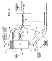
- the coating machine such as spray machine S further includes at least one material application mechanism or coating device 4 that sprays or otherwise deposits or applies a coating material M ( Fig. 2 ) to a surface of the rotating workpiece, such as the inside surfaces of a beverage can for example.
- the particular application mechanism or coating device 4 selected will depend on many factors including but not limited to the characteristics of the material being applied such as viscosity, flow rates, required spray patterns if any, temperature, pressure and so on. Any number of many different types of material application devices may be used with the present invention. Examples include but are not limited to a spray applicator or spray gun Models A20A or MEG, available from Nordson Corporation, Westlake, Ohio.
- the application mechanism or spray gun 4 may be supported on any suitable structure, including a robotic arm, for example, so that the spray gun position may be manually or automatically controlled as the case may be.
- the spray gun 4 operates in response to a number of control signals and functions, including an on/off control or trigger function T ( Fig. 2 ).
- This trigger control function is typically realized in the form of one or more electrical or pneumatic drive signals that instruct the spray gun 4 to turn on and off.
- the trigger control T will take an appropriate voltage/current waveform in relation to the type of spray gun 4 being controlled.
- a typical coating system may include multiple spray lines and each spray line may use one or more spray guns at one or more spray stations. More than one type of spray gun may be used in the various spray lines or even within a single spray line.
- the trigger signal T is a generic reference to the timing signals and associated drive signals or waveforms that cause the spray gun to turn on and off at selected times.
- the trigger signal T may be generated by an appropriate control circuit, such as, for example, a gun control circuit as described herein below, or other suitable control circuit.
- Each spray line may include one or more spray machines S.
- Each spray machine S typically includes a spray machine control system E.
- the spray machine control system E typically is realized in the form of a PLC or other suitable programmable control circuit.
- the control system E controls a spray time window F (also see signal 270, Figs. 9 and 10 ) when the control system E has positioned a can for a coating operation and is rotating the can via the drive D.
- the spray machine control system E may be realized, for example, as an electronic circuit in the form of any programmable digital or analog control circuit. Other control systems however, including mechanical controls, may be used in appropriate applications.
- the control functions C of the spray machine control system may include control of the spray applicator 4, the drive mechanism D ( Fig. 1 ) and a supply 20 ( Fig. 2 ) of material to the spray applicator 14.
- the supply 20 may be realized in the form of any of a wide variety of pump supply systems, for example, well known to those skilled in the art or later developed.
- each spray machine S includes two spray guns 4 and two drive systems D. Note that Figs. 1 and 2 only illustrate a single gun and drive mechanism for clarity.
- Fig. 1 illustrates an exemplary spray machine S comprised of the star wheel 1 supporting a number of workpieces W such as cans 3 generally facing opposite a spray gun 4.
- a spray machine S may include only one coating station such as shown in Fig. 1 or may include two or more coating stations each having a star wheel and spray gun.
- Each can 3 has an open end, and a closed end that is supported on a rotating vacuum chuck 10 ( Fig. 2 ).
- Fig. 1 one can at a time is in the spray position opposite to the gun (also referred to herein as in the spray 'pocket').
- the star wheel 1 sequentially indexes the cans into the spray position opposite the gun.
- the star wheel 1 may have a number of vacuum chucks 2 supporting the cans 3, with one can 3 at a time positioned opposite the spray gun 4.
- the star wheel 1 with each of the vacuum chucks 2 is rotated or indexed by a shaft 5 connected to a motor 7 so as to position the next can to be coated opposite the spray gun 4.
- each vacuum chuck 2 includes a driven member 17 (like a pulley wheel for example) that is rotated by a belt and motor or other suitable drive mechanism (not shown).
- a vacuum line 8 is connected from a vacuum source 19 ( Fig. 2 ) to each vacuum chuck 2 so that the force resulting from the vacuum suction is used to secure or hold the can to its respective chuck 2.
- a vacuum sensor 9 is provided to monitor the vacuum level at the vacuum chuck 2 to ensure that there is enough vacuum induced pressure to properly secure the can to the rotating chuck.
- the rotating chuck 2 may be provided with metal or other suitable speed targets 10 that rotate past an optional speed sensor 11 that monitors or detects the speed of the rotating chuck to ensure that the chuck 2 and the can 3 are rotating at a proper coating speed.
- an optional speed sensor 11 that monitors or detects the speed of the rotating chuck to ensure that the chuck 2 and the can 3 are rotating at a proper coating speed.
- the speed sensor 11 output thus may be a signal that varies with the speed of the chuck, or may include circuitry that outputs a signal indicating whether the detected speed is within an acceptable range, or any other suitable speed indicating signal as the case may be for a particular control system design.
- the speed detection may be performed while a can is present in the spray pocket, or when outside the spray pocket.
- a can-in-position or can-in-pocket (CIP) sensor 12 monitors the presence of a can in the spray position and an optional gun-in-position sensor 13 ensures that a spray gun is in the proper position for spraying the can during a coating operation.
- a proximity sensor 13 or other suitable detector may be positioned so as to detect the properly positioned gun. Thereafter, if the gun position changes, the sensor 13 output will change to indicate the gun is no longer in its correct position for a coating operation.
- an automatic gun positioning arrangement such as a robotic arm for example -- the associated motor or motor control may output a signal when the gun is properly positioned, or a proximity sensor may still be used.
- An optional safety guard sensor 14 ensures that the safety cage G has been positioned and/or locked around the spray machine before it begins to rotate to protect any operator in the area.
- the exemplary embodiments herein illustrate a vacuum chuck
- inventive concepts herein are not necessarily limited to the use of a vacuum chuck, but rather a more general concept of monitoring or detecting that a can to be sprayed is being adequately held in place, however that determination may be made.
- the concept below of a coating operation control signal may be implemented based on monitored conditions that do not include a vacuum chuck or the holding force of the can on the star wheel.
- one of the inventive aspects of the disclosure is to provide a control signal for a coating operation that is used to indicate that the system is ready to spray ("RTS"), or in other words a 'good-to-go' (“GTG”) coating operation control signal 22.
- the good-to-go or ready-to-spray coating operation control signal thus functions as a go/no-go indicator to an operator and/or a control circuit that various selected conditions are okay to allow a coating operation to begin.
- the selected conditions may be chosen based on overall requirements for a particular application, and in general will typically relate to those conditions that if not acceptable should inhibit a coating operation or at least result in a warning indication of some suitable format.
- the CIP condition and the adequate vacuum condition are the chosen minimum conditions that must be acceptable since these conditions can significantly affect the quality of the applied coating material.
- the speed condition, guard position and gun position may also be deemed important enough to form part or all of the criteria for the go/no-go control signal.
- the CIP and/or vacuum conditions may be deemed optional.
- the developed control signal 22 may be based on these exemplary conditions, a subset thereof, or additional and different monitored conditions as a matter of design choice.
- the characterization of the control signal 22 as being a go/no-go type signal is merely one exemplary embodiment in which the control signal 22 may be used to enable or inhibit a coating operation.
- the control signal 22 may simply issue a warning signal of some suitable format (such as a warning light, buzzer, screen icon and so on) that indicates to the operator that there is a fault condition in one or more of the selected conditions being monitored to generate the control signal 22.
- the control signal 22 therefore is more generally to be understood as developed from a multifunction set of input conditions and an output state that indicates whether there is a fault or other abnormality condition in one of more of the input conditions.
- the control signal 22 may be used to automatically inhibit a coating operation on a can by can basis, to inhibit a coating operation if the fault condition persists past a pre-selected number of coating operations, or may provide an indication or warning to the operator, allowing for the operator to decide whether to inhibit or continue with a coating operation.
- the speed sensor 11 produces an output signal 11a that may be a signal that simply indicates whether a minimum acceptable speed is detected, or may be an actual speed based signal that is then interpreted by other circuits in the system to determine if the speed is within an acceptable range for a coating operation.
- the vacuum sensor 9 produces an output signal 9a that may be a signal that simply indicates whether a minimum acceptable vacuum is detected, or may be the actual vacuum based signal that is then interpreted by other circuits in the system to determine if the vacuum is within an acceptable range for a coating operation.
- the CIP sensor 12 generates a signal 12a that indicates whether a can is in position for a coating operation.
- the gun in position sensor 13 produces a signal 13a that indicates whether the spray gun 4 is in position for a coating operation
- the guard position sensor 14 produces a signal 14a that indicates whether the safety device 14 such as a protective cage is in position for a coating operation
- the signals from these five sensors 9, 11, 12, 13 and 14 are input into a multifunction spray machine monitor circuit 15.
- the multifunction machine monitor circuit 15 may execute a wide variety of monitor and control functions for the system S, or in a simplified embodiment may receive the monitored condition signals, such as from the five sensors described herein for example, and produce the control signal 22 output to a control circuit such as, for example, a spray monitor circuit module 18.
- the multifunction machine monitor circuit 15 may execute, monitor and control one or more functions associated with the system S locally, rather than having those functions controlled from a remote or distant location such as over a network.
- the monitor circuit 15 may be used to locally regulate the base pressure of the coating material for the spray gun 4 as a function of a commanded base pressure that is part of a coating operation recipe.
- the monitor circuit 15 may be used to regulate back pressure at the source 20 pump regulator, for example.
- the monitor circuit 15 may locally regulate temperature of the coating material for the spray gun 4 based on a commanded temperature that may be part of a coating operation recipe.
- the monitor circuit 15 may monitor the conditions from the condition sensors and generate the go/no-go control signal 22.
- the control signal 22 may be generated in any circuit within the over system S. Other local control functions may be executed as needed for particular systems S.
- a remote display may be provided to allow an operator to observe coating operation conditions and parameters while the operator is physically near the machine, rather than having to be possibly in a more remote location.
- the monitor circuit 15 is preferably used for local control and monitor functions, it is contemplated that in a preferred but not required embodiment the monitor circuit 15 will be physically located in fairly close yet practical proximity to the spray machine S, such as in an electrical box mounted on or near the spray machine. This arrangement, for example, can be particularly useful for pressure regulation and the remote monitor functions, and minimizes or reduces interface wiring.
- Each circuit 15 may operate for a single gun spray machine, or in the case of the exemplary embodiment of Fig. 8 operate for two spray guns per spray machine, although such circuits may alternatively operate for more than two spray guns.
- control signal 22 in one embodiment may be realized in the form of a simple AND logic function that can be realized in any circuit located anywhere convenient, or as part of a more complex control circuit 15 or 18.
- the control signal 22 may alternatively be developed as a software signal for example.
- the actual implementation and form of the circuits, signals and controls may be software, hardware, a combination thereof, or otherwise largely a matter of design choice based on the overall design criteria of the system. Therefore the words 'circuit', 'system', 'signal' and 'control' should be very broadly interpreted to include any form of realization of these features including software, hardware or a combination thereof as the case may be.
- the spray monitor circuit 18 may be, for example, an iTraxTM system noted herein above, with the monitor circuit 15 being an add-on feature or module to such a system.
- the monitor circuit 15 If the appropriate inputs are received from all five sensors indicating that the system is ready to spray (in other words, none of the input signals being monitored indicates a fault condition), then the monitor circuit 15 outputs the control signal 22 in a first state indicating that the machine is ready to spray (a GTG or RTS signal). This state of the control signal may thus be used as an enable signal to permit a coating operation to proceed. If one or more sensors do not provide an appropriate signal to the monitor circuit 15 (in other words, at least one or more of the signals being monitored indicates a fault condition), then the control signal 22 will be output from the monitor circuit 15 in a second state indicating the machine is not ready to spray. This state of the control signal may thus be used as an inhibit or disable signal to prevent a coating operation from proceeding. Alternatively, the second state may be used as a warning or to generate an appropriate warning to the operator that a fault condition has been detected, whether or not the control signal second state is used as an automatic coating operation inhibit function.
- one of the inventive teachings of the present disclosure is that a customer can select that a can will not be sprayed with coating unless the can is securely held to the chuck, is rotating at the proper speed and is in the right position for a coating operation, and unless the spray gun is in the right position as well with the safety cage secured around the machine.
- These sensors, or any subset thereof, or other sensors as needed help to ensure that certain of the problems that can cause cans to be improperly sprayed are detected before the cans are sprayed with coating material.
- these sensors alone or in combination with the multifunction spray machine monitor 15 improve the control capabilities of the spray monitor system 18 such as an iTraxTM system.
- the multifunction spray machine monitor circuit 15 may be used to provide electrical power to the various sensors, and to receive the output signals therefrom.
- the monitor circuit 15 generates the multifunction control signal 22 based on the received sensor signals.
- the control signal 22 is hard wire input to the spray monitor circuit 18 (such as an iTraxTM system, for example).
- the control signal 22 may be sent to any other control circuit or function that shuts down the spray machine when one or more of the monitored conditions is at fault, and/or issues a warning signal as described above.
- the spray monitor circuit 18 includes power relay contacts ( Fig. 9 ) that open and shut off the associated spray machine S if the control signal 22 is a false (indicating a fault condition exists).
- spray machine shutdown may be effected by a different control circuit or a different technique.
- spray machine power contacts may also be provided with the monitor circuit 15 itself.
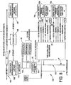
- FIG. 1A we show a system level functional block diagram of a spray machine monitor and control system embodiment 200 such as may be used, for example, with the spray machine S of Figs. 1 and 2 .
- Fig. 1A is illustrated for a single spray machine, it being understood that additional monitor control systems may be added to the network bus as required for a complete spray line or multiple spray lines.
- the basic system of Fig. 1A may be an original build, or may be a modified system based on a previously installed or available system such as an iTraxTM system.
- a computer or controller 108 may be provided as an operator interface, such as a personal computer for example.
- the computer 108 stores or may be used to input one or more recipes that an operator may select based on the type of coating material to be applied and the type of work piece W.
- a recipe may be used on a single spray machine, multiple spray machines, a single spray line, multiple spray lines and so on.
- a typical recipe may include a variety of parameters such as, for example, coating material base and fire pressures, gun trigger timing, flow rates, temperature, rotation speed and so on.
- the PC 108 communicates with the control system 200 over a suitable network, such as a CAN network 112.
- each module 202 may receive all or a portion of a particular recipe that will be executed by the associated spray machine.
- each spray machine has an associated spray monitor circuit module 18, gun control circuit module 204 V and a multifunction spray machine monitor module 15.
- gun control circuit modules 204 may be added to the network 112.
- a single gun module may contain circuitry for multiple spray guns in the spray machine.
- Fig. 1A is exemplary and intended to show functional relationships.
- the drawings do not necessarily imply or require a specific physical embodiment of the various circuits.
- the block diagrams herein are based on a configuration that may be used to modify or add functionality to an existing system such as an iTraxTM system. But such need not be the case, and the physical embodiment of, for example, Fig. 1A may be realized with an original build.
- various functions may be carried out by different modules, either those shown or others, or a module type system would not be required in all cases, but for example, a single circuit system could be connected to the network.
- An advantage of a modular system is that it allows a designer to choose what functionality is to be included in a particular system, and also allows for ease of expansion to a larger system.
- Recipes or portions thereof may be downloaded or transferred from the PC 108 to each module 202 as need be.
- the PC 108, converter 110, CAN network 112 and one or more spray monitors 18 may be part of a pre-installed iTraxTM system. Alternatively, these portions may be provided as part of a new installation.
- the spray monitor circuit 18 may include spray machine power control relay contacts 206 that open when the spray monitor circuits 18 determines that the spray machine should be shut down.
- the spray monitor circuit 18 receives the control signal 22 (GTG or RTS) from the multifunction spray machine monitor circuit 15. If the control signal 22 indicates the spray machine is not ready, the spray monitor circuit 18 may hold the contacts 206 open until the fault conditions are fixed. Operator overrides may also be provided if so required.
- the spray monitor circuit 18 also receives a pressure signal 46 from a pressure regulation and controller circuit 42 ( Figs. 4 and 5 ) that relates to base and/or fire pressure of the coating material at the spray gun. The spray monitor circuit 18 may interrupt the spray machine via the contacts 206 if an out of range pressure condition is detected.
- the spray monitor circuit 18 may also use the pressure signal 46 to provide a real time gun spray duration feedback signal 208 to the gun control circuit 204 as will be more fully described below to determine true spray duration in real time.
- the spray monitor may also receive a gun trigger signal 210 from the gun control circuit 204 so that an operator can visually note if the spray gun is firing correctly, and compare that to the actual spray duration time.
- the gun trigger signal 210 in one embodiment is a digital signal that reflects the on and off times that the gun control circuit 204 commands the gun to operate for a given coating operation. In other words, it may be a digitized version of the actual drive signal sent to the spray gun 4 by the gun control circuit 204 for a coating operation.
- the real time spray duration feedback signal 208 is the actual spray duration produced by the gun during a coating operation in response to the gun trigger signal 210.
- the subsequent gun trigger signal 210 corresponds to the actual drive signal for the next coating operation and reflects compensation based on the real time spray duration feedback.
- the spray monitor may also monitor flow parameters based on the received pressure signals.
- the gun control circuit module 204 may be used to generate appropriate gun drive signals 212 as well as to adjust the trigger and drive signals to achieve the commanded spray duration based on the real time feedback signal 208.
- the gun control circuit may also be used to operate a clean spray gun operation.
- the multifunction spray machine monitor circuit module 15 may be used to carry out pressure regulation and temperature control as will be described below.
- Still another module 202 may be a remote display 70 ( Fig. 7 ) as will be further described below.
- the remote display 70 for example may be used to display the same data that is placed on the bus 112, but at a location proximate the spray machine.
- the remote display 70 communicates via the multifunction spray monitor 15, but alternatively may communicate through different modules or directly to the bus 112 as represented by phantom line 214 in Fig. 1A .
- the computer 108 may also be used for data logging information placed on the bus 112 by any of the modules 202. As done, for example, with the iTraxTM system, the computer 108 may also be used for module configuration and system calibration processes as required.
- the coating material In order to achieve good can coating, it is also necessary that the coating material be properly supplied or delivered to the spray gun 4.
- Two of the primary factors in the nature of the coating material for good coating operations are the pressure and temperature of the coating material.
- the local pressure control is realized by monitoring the pressure of the coating material in or proximate the spray gun, rather than at a more distant location in the fluid circuit.
- the exemplary embodiment of the monitor circuit 15 in relative close proximity to the spray machine is useful for also implementing a locally controlled pressure and temperature profile of the coating material, although the pressure and optional temperature monitoring and regulation may alternatively be performed by a separate or different control system.
- Fig. 4 shows an exemplary embodiment of a fluid circuit 30 that includes a fluid pressure transducer 32 at the output of a fluid regulator 34 to monitor the pressure of the coating material being supplied to the spray gun 4.
- a separate fluid circuit 30 may be used for each spray gun in a system or two or more guns may share a common fluid circuit as needed.
- the fluid circuit 30 may also include an air regulator 36 for the fluid regulator 34, as well as a bypass valve 38 for manual override of the air regulator 36.
- a pressure gauge 40 may be provided for visual verification of the pressure of the material supplied to the spray gun 4 when in a manual override mode of operation.
- a pressure control circuit 42 may be provided that allows for local regulation and control of the fluid pressure delivered to the spray gun 4, based on a commanded base pressure 45, such as for example received from the spray monitor circuit 18.
- base pressure is meant the steady state pressure of the material supplied to the gun, and the fire pressure is the fluid pressure when the gun is actually outputting material through a nozzle or other output orifice.
- the spray monitor circuit 18 may receive the target (i.e., commanded) base pressure as part of a recipe download. As will be described below, the spray monitor 15 may also adjust the base pressure setting in relation to a wrap count.
- the pressure control circuit 42 locally controls the fluid pressure supplied to the gun 4 by adjusting the air pressure delivered to the fluid regulator 34 based on the sensed fluid pressure (in the form of signal 43) from the first pressure transducer 32.
- the manual override is provided, for example, in case the control circuit 42 should fail.
- the operator can use the bypass valve 38 to manually adjust the output pressure as read from the manual gauge 40.
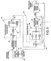
- the control schematic of Fig. 5 shows the incorporation of the hardware of Fig. 4 in a closed control loop for controlling the pressure of the coating material supplied to the spray gun 4.
- the fluid pressure transducer 32 of Fig. 4 is referred to as pressure sensor 1.
- Pressure sensor 2 of Fig. 5 is a second fluid pressure sensor 44 inside the gun 4 or at close proximity to the spray gun 4.
- close proximity or proximate is simply meant that the gun pressure sensor 44 is located in the fluid circuit sufficiently close to the gun so that its reading is substantially the same as the fluid pressure inside the gun.
- the second pressure sensor 44 and sensor head mounting is shown in US Patent Number 5,999,106 that is hereby incorporated by reference in its entirety.
- the output signal 46 from pressure sensor 2 may be input to the spray monitor circuit 18 and used to determine the regulated base and/or fire pressure signal 47.
- the spray monitor circuit 18 outputs the sensed pressure value 47 and also a commanded pressure value 48 to the multifunction spray machine monitor circuit 15. In the exemplary embodiment, this communication is performed over a network such as, for example, the CAN network 112 or other suitable network or communication system.
- the monitor circuit 15 receives the commanded pressure value and sensed pressure value and through a conventional sample, gain and offset circuit 50 (or other suitable error detection algorithm and circuit) determines an error value or regulation signal 52 when the measured pressure in the spray gun differs from the commanded pressure.
- While the local pressure regulation provides for more accurate and responsive pressure regulation in the spray gun, the exemplary embodiment also allows other optional advantages to be realized.
- internal security functions within the overall control system such as an ITrax system for example
- the system may be provided with an electronic override knob adjustment when necessary since the spray monitor circuit 18 will typically include a visual display for the operator.
- Communication between the local pressure regulation function 42 and the spray monitor circuit 18 and the PC 108 over a network (116 in Fig. 8 ) or through other data links also facilitates data display and logging of the actual pressure in the spray gun 4.
- the pressure regulation concepts of the present disclosure are illustrated with reference to a fluid circuit 250 for supplying fluid to a spray gun 4.
- the spray gun 4 typically includes a nozzle 252 through which coating material M is discharged at a typical flow rate Q.
- the spray gun communicates with a main flow Q through a controlled orifice plate 254.
- the second or gun pressure sensor 44 detects fluid pressure between the controlled orifice plate and the nozzle. When the gun is off, the sensor 44 measures the base pressure 256, and after the gun turns on this pressure drops to a fire pressure 258. There are inherent turn on and turn off delays between the trigger or drive signal 260 and the actual spray duration represented by time X.
- pressure regulation may be implemented at the back pressure regulator 262 associated with a pump 264 for supplying coating material to the spray guns, using a third pressure sensor 266.
- An exemplary process includes the spray monitor circuit 18 determining a wrap number that is based on the rotation speed of the workpiece and the actual spray time duration X. The faster the speed, the higher the number of wraps for a given spray duration (spray duration being indicated by the known actual gun on and off times). The slower the rotation speed the lower the number of wraps for a given spray time duration. Typically, the spray monitor 18 will have a range for an acceptable wrap number for the various recipes. If the system determines that the wrap number is low, the system may command an increase in the base pressure at the gun (locally regulated as described herein above with respect to Figs.
- the system determines that the wrap number is high, it can command a lower base pressure at the gun.
- the spray monitor 18 or other control circuit can actively control the spray weight of the coating material as the rotation speed varies (or for example as temperature varies when active temperature control is not used.)
- the pressure changes for wrap number may be automatically implemented or the system could send a message or request for the operator to decide whether to approve the pressure change.
- Fig. 6 illustrates the gun fluid pressure sensor 44 connected by an armored cable 60 to a spray gun 4 that may be used with the present inventions.
- the spray gun 4 is preferably but not necessarily an electrically operated spray gun such as a MEG gun available from Nordson Corporation and shown in US Patent Number 5,791,531 which is incorporated herein by reference in its entirety.
- a temperature sensor 62 may be disposed adjacent or near to the pressure sensor 44 to sense the temperature of the coating material in the gun 4.
- the temperature sensor 62 may be, for example, a conventional RTD type sensor although other temperature sensors may be used as required.
- the wires associated with the temperature sensor 62 may be routed through the armored cable 60 with the wires for the pressure sensor 44.
- Signal conditioning circuitry for the temperature sensor output signal may conveniently be provided in the amplifier section 64.
- the coating temperature value 66 ( Fig. 8 ) provided by this sensor 62 may be used to control a conventional heater ⁇ chiller 68 ( Fig. 8 ) in the fluid circuit, or other temperature adjusting system, to raise or lower the temperature of the coating material as necessary.
- a closed loop control function such as a PID control loop may also be used for the closed loop temperature control.
- the spray monitor circuit 18 may adjust the recipes based on the detected temperatures. By monitoring and controlling the pressure and temperature of the coating material at the gun, the spray monitor circuit 18 can verify that the material delivery system is properly operating for a coating operation.
- the pressure regulation function is preferably done locally so as to provide faster real time closed loop control of the material pressure at the spray gun 4
- temperature of the coating material typically changes at a slower rate than pressure. Therefore, the closed loop temperature control function may if desired be executed in the spray monitor circuit 18 rather than having a local control loop in the spray machine monitor control circuit 15, although the latter may be done as an alternative. For existing systems this allows the temperature control loop function to remain in place, but adding in the feature of monitoring the actual coating material pressure at the gun.
- the command and control signals for controlling the heater/chiller unit 68 may communicate over the network since closed loop response time is slow compared to local pressure regulation.
- Fig. 7 shows a remote display 70 inventive feature of the present disclosure.
- a multifunction spray machine monitor circuit 15 for each spray machine S and there may be several multifunction spray machine monitor circuits 15 communicating with a single primary control circuit computer that is monitoring the operation of several spray machines in a can manufacturing facility. It may be useful in some applications to have information concerning the operation of the spray machine right at the spray machine for the operator to observe. However, it is cumbersome to attempt to put the primary computer at the spray machine and of course a single computer cannot be located at several spray machines. Therefore, the display shown in Fig.
- the remote display 70 may be positioned at or proximate to the spray machine so that the operator can monitor parameters and operation of individual spray stations.
- Up and down switches 72, 74 of the remote display may be provided to scroll through menus presented on the screen 76, such as for example, coating material fluid pressure in psi, bar or kpa (kilopascals) at the spray gun 4, coating material temperature at the spray gun 4 in F° (Fahrenheit) or C° (centigrade) , speed of the rotating can in rpm (e.g. chuck speed) or production rate of the spray machine in cpm (cans coated per minute).
- a toggle switch 78 may be provided, for example, to switch between spray machines.
- two spray stations e.g. two star wheels and two spray guns
- a units button 80 may be used to allow the operator to select the units 82 listed on the side of the display.
- Providing the ability to display this information at each spray machine through a remote display such as the one shown in Figure 7 is highly advantageous to the customer. Because the machine monitor circuit 15 communicates over the network bus to the primary control circuit 18, the information and data displayed on the remote display 70 advantageously is the same data that is being sent to and logged by the primary control circuit 18.
- Fig. 8 illustrates an exemplary architecture for an overall system 100 such as may be used with the various inventions herein especially but not necessarily in cooperation with a pre-existing system such as an iTraxTM system.
- Internet or other network or communication access may be provided by any suitable system 102 such as an ISP connection 104 to a customer or user Ethernet hub 106.
- a remote client computer 107 may be provided for additional user interface locations, but such remote clients are to be distinguished from the remote display 70 that preferably is located at or proximate a spray machine.
- a suitable computer 108 (for example, the computer in Fig. 1A ) may be used with a conventional USB to CAN network interface 110 to allow a user to communicate with one or more spray monitor circuits 18 (three such circuits are represented in Fig.
- a CAN network is shown in the exemplary embodiments, any suitable communication system may be used for a particular system. Since there may be typically two spray gun stations for each spray machine, sensor inputs and other control and monitoring functions associated with two spray guns 4a and 4b are shown connected to a single multifunction spray machine monitor 15 (note in Fig. 8 the details for only one of the spray monitor circuits 18 interfacing to a machine monitor circuit 15 is shown).
- Digital Display 1 may be a first remote display 70a like the example in Fig. 7 provided with respect to one gun of the spray machine at any convenient location close to the spray machine.
- Pressure Regulator 1 (42a) represents the pressure control loop 42 that produces a feedback signal 46a similar to the feedback signal 46 provided by the closed loop control system 42 of Fig. 5 .
- This feedback signal 46 may be input to the spray monitor 18 over the network.
- Spray Machine First Pocket 4a represents the sensor inputs from a spray machine, when used, from the vacuum sensor, rotational speed sensor and can-in-pocket sensor for one gun of the spray machine. Although not shown, the sensor readings for the gun-in-position sensor and safety guard sensor may also be provided when used.
- the temperature sensor value 66 from the spray gun (as explained with respect to Fig. 6 herein) may be provided and a control signal would be provided that is sent over the CAN network 112 via the multifunction spray machine monitor 15.
- the temperature control command 67 to the TCU 1 (temperature control unit 1) to control the temperature of the coating material may be received from the spray monitor circuit 18, also over the CAN network 112. Similar connections and interfaces are provided for the second spray gun that is monitored by the monitor circuit 15.
- the spray monitor 15 may be used to shut down the spray machine if pressure and/or temperature of the material are unacceptable or out of range.
- a CAN to CAN buffer 114 may be used to interface the machine spray monitor circuit 15 to the CAN bus 116 that communicates with the spray monitor circuits 18 and the PC 108.
- the buffer 114 functions as a repeater or buffer to create an isolated network, so that if a fault occurs in one or more of the monitor circuits 15 or other modules, the spray monitor circuits 18 will be isolated and still able to control and monitor operation of the spray machines.
- the spray monitor circuit 18 receives or generates a trigger signal T ( Fig. 2 ) to trigger the spray gun. If both the trigger signal and coating operation control signal 22 are present, the can in position is sprayed. There are at least two other possible scenarios in the exemplary embodiment:
- the monitor circuit 15 thus provides monitoring of selectable conditions to generate a coating operation control signal.
- the proximate location of the monitor circuit 15 to the machine stations also facilitates local pressure and temperature control and regulation of the coating material for the spray guns.
- the gun control circuit or module 204 operates to adjust the gun on/off times and also may optionally selectively generate drive signal voltage and current wave forms in relation to the type of spray gun being used.
- the timing parameters preferably are based on the real-time fluid pressure feedback signal 46 from the spray gun pressure sensor 44.
- the feedback signal 46 is ideally represented in Fig. 5A and the actual spray duration time X can easily be determined from this signal in real time.
- a simple threshold detector circuit may be used to detect the transition events between the base and fire pressure levels.
- Other techniques may be used to derive the spray duration time from the real time pressure signal 46.
- the signal 46 is input to the spray monitor circuit 18, which may include the spray machine shutdown contacts 206 that open if the pressure signal 46 indicates the material pressure is out of acceptable range.
- Some spray guns 4 include cleaning mechanisms 300 ( Fig. 2 ) for the spray nozzles to keep the nozzles free from buildup of the coating material.
- the gun control circuit 204 may further be configured to control the cleaning mechanism 300 as appropriate with a clean spray control signal 274.
- Fig. 12 illustrates a control circuit 500 that may be used in systems that incorporate clean spray technology.
- the spray gun 4 responds to a first control signal 502 for a coating operation, and a second control signal 504 for a clean spray operation during which the nozzle may be clean of contamination and residue.
- a logic AND gate 506 along with a first logic inverter 508 produces an first output 510 that can only the clean spray signal 504 is true and the coating control signal 502 is false.
- the gun control circuit may also be configured to prevent an operator from attempting to program spray gun operation that is outside the capabilities of the gun. For example, if an operator tries to fire a gun more quickly than it can function and still apply a good coating, the gun control circuit may interrupt the spray machine or lock out the requested change.
- control functions, monitoring functions and operation of the various modules described herein may be realized using well known hardware and software design criteria, or others later developed.
- Trace C in a simplified manner illustrates how the actual spray duration (actual time period that coating material is applied to a work piece) can vary from the control signal of trace B based on gun on and off delays, for example.
- Trace D illustrates in an idealized manner a typical pressure signal 46 from the spray gun pressure sensor 44, and trace E represents a timing signal that may be derived from the pressure signal 46 and used to adjust the drive signal 212 on the subsequent cycle (represented by the feedback line 410 in Fig. 10 ).
- FIG. 11 another advantage that may optionally be derived from the modular concept, is a daisy chain wiring concept that may significantly reduce time, labor and complexity of wiring a system in the field.
- three gun control modules 430, 432 and 434 are shown.
- two gun control circuits were discussed since the exemplary spray machine only used two spray guns. But other spray machines may use more than two spray guns.
- various signals 435 used by the gun control modules may be common.
- the gun control modules will all use the CIP signal, an index signal (which indicates the star wheel position, spray duration times, power, ground and so on.
- the gun control circuits 430, 432 and 434 all respond to or interface with the same spray monitor circuit 18, there is an opportunity to simplify wiring by providing a daisy chain between the gun control modules such as for example with a ribbon cable 436.
- the modules may be arranged in a master/slave configuration (for example, in Fig. 11 the gun control 1 may be the master and the others the slaves) so that a shift register or similar timing scheme such as executed in software may be used to control when data on the ribbon cable is valid for which module in the chain.
- a time multiplexing scheme may alternatively be used.
- This daisy chain approach reduces wiring to each individual module. It may also be implemented with other modules used in the overall system.
Applications Claiming Priority (2)
| Application Number | Priority Date | Filing Date | Title |
|---|---|---|---|
| US74679006P | 2006-05-09 | 2006-05-09 | |
| EP07755839A EP2019733A2 (de) | 2006-05-09 | 2007-04-23 | Steuersystem zur beschichtung von dosen |
Related Parent Applications (2)
| Application Number | Title | Priority Date | Filing Date |
|---|---|---|---|
| EP07755839.3 Division | 2007-04-23 | ||
| EP07755839A Division EP2019733A2 (de) | 2006-05-09 | 2007-04-23 | Steuersystem zur beschichtung von dosen |
Publications (2)
| Publication Number | Publication Date |
|---|---|
| EP2241378A2 true EP2241378A2 (de) | 2010-10-20 |
| EP2241378A3 EP2241378A3 (de) | 2015-03-25 |
Family
ID=38521812
Family Applications (2)
| Application Number | Title | Priority Date | Filing Date |
|---|---|---|---|
| EP20090013521 Ceased EP2241378A3 (de) | 2006-05-09 | 2007-04-23 | .steuersystem zur beschichtung von dosen |
| EP07755839A Withdrawn EP2019733A2 (de) | 2006-05-09 | 2007-04-23 | Steuersystem zur beschichtung von dosen |
Family Applications After (1)
| Application Number | Title | Priority Date | Filing Date |
|---|---|---|---|
| EP07755839A Withdrawn EP2019733A2 (de) | 2006-05-09 | 2007-04-23 | Steuersystem zur beschichtung von dosen |
Country Status (5)
| Country | Link |
|---|---|
| US (4) | US8578878B2 (de) |
| EP (2) | EP2241378A3 (de) |
| JP (1) | JP5441687B2 (de) |
| CA (1) | CA2652313A1 (de) |
| WO (1) | WO2007133386A2 (de) |
Cited By (1)
| Publication number | Priority date | Publication date | Assignee | Title |
|---|---|---|---|---|
| US9878340B2 (en) | 2010-10-20 | 2018-01-30 | Sata Gmbh & Co. Kg | Color application system and method for operating the same |
Families Citing this family (50)
| Publication number | Priority date | Publication date | Assignee | Title |
|---|---|---|---|---|
| DE502007000825D1 (de) | 2006-12-05 | 2009-07-16 | Sata Gmbh & Co Kg | Belüftung für den Fließbecher einer Farbspritzpistole |
| WO2008131381A1 (en) * | 2007-04-23 | 2008-10-30 | Nordson Corporation | Configuration of a can coating system using one button |
| CN101970127B (zh) | 2008-03-12 | 2014-11-12 | 杰弗里·D·福克斯 | 用后可弃的喷枪筒管 |
| DE202008014389U1 (de) | 2008-10-29 | 2010-04-08 | Sata Gmbh & Co. Kg | Fließbecher für eine Farbspritzpistole |
| DE102009021608B4 (de) * | 2009-05-15 | 2015-10-15 | Airbus Operations Gmbh | Einrichtung und Verfahren zum Lackieren gekrümmter Außenoberflächen eines Luftfahrzeuges |
| DE102009032399A1 (de) | 2009-07-08 | 2011-01-13 | Sata Gmbh & Co. Kg | Farbspritzpistole |
| GB0919059D0 (en) * | 2009-10-30 | 2009-12-16 | Sencon Europ Ltd | Application and inspection system |
| DE102010018617A1 (de) * | 2010-04-28 | 2011-11-03 | Robert Bosch Gmbh | Verfahren und Vorrichtung zum Überwachen einer Mehrzahl von Sensorsignalen |
| DE202010007355U1 (de) | 2010-05-28 | 2011-10-20 | Sata Gmbh & Co. Kg | Düsenkopf für eine Spritzvorrichtung |
| KR101247810B1 (ko) * | 2010-11-19 | 2013-04-03 | 엘에스산전 주식회사 | 온도 제어 모듈 |
| US9333519B2 (en) | 2010-12-02 | 2016-05-10 | Sata Gmbh & Co. Kg | Spray gun and accessories |
| CN102129230A (zh) * | 2010-12-30 | 2011-07-20 | 日泰(上海)汽车标准件有限公司 | 一种涂覆机的电路设计 |
| FR2975926B1 (fr) * | 2011-06-06 | 2019-08-02 | Soluscope Sas | Dispositif securise d'assemblage demontable |
| RU2601337C2 (ru) | 2011-06-30 | 2016-11-10 | САТА ГмбХ унд Ко. КГ | Пистолет-краскораспылитель с возможностью легкой очистки, принадлежности для пистолета-краскораспылителя и способ их монтажа и демонтажа |
| US9652018B2 (en) * | 2011-12-30 | 2017-05-16 | Intel Corporation | Adjusting power consumption of a processing element based on types of workloads to be executed |
| US9937512B2 (en) * | 2012-02-07 | 2018-04-10 | United Technologies Corporation | Integrated multicoat automatic pause resume circuit |
| TW201434535A (zh) * | 2013-03-05 | 2014-09-16 | Genesis Photonics Inc | 噴塗裝置 |
| CN104056753A (zh) * | 2013-03-20 | 2014-09-24 | 新世纪光电股份有限公司 | 喷涂装置 |
| JP6086823B2 (ja) * | 2013-06-11 | 2017-03-01 | 三菱マテリアルテクノ株式会社 | 塗装装置及び塗装方法 |
| CA155474S (en) | 2013-09-27 | 2015-08-27 | Sata Gmbh & Co Kg | Spray gun |
| DE202013105779U1 (de) | 2013-12-18 | 2015-03-19 | Sata Gmbh & Co. Kg | Luftdüsenabschluss für eine Lackierpistole |
| US20150241870A1 (en) * | 2014-02-26 | 2015-08-27 | The Boeing Company | Portable computer and associated method of modeling a sealant spraying process |
| CN103920623B (zh) * | 2014-04-15 | 2016-08-31 | 中南大学 | 一种用于喷射点胶过程的一致性控制方法及系统 |
| USD758537S1 (en) | 2014-07-31 | 2016-06-07 | Sata Gmbh & Co. Kg | Paint spray gun rear portion |
| CA159961S (en) | 2014-07-31 | 2015-07-17 | Sata Gmbh & Co Kg | Spray gun |
| CN105289870B (zh) | 2014-07-31 | 2019-09-24 | 萨塔有限两合公司 | 喷枪的制造方法、喷枪、喷枪本体以及盖 |
| USD768820S1 (en) | 2014-09-03 | 2016-10-11 | Sata Gmbh & Co. Kg | Paint spray gun with pattern |
| US9889460B2 (en) * | 2014-09-11 | 2018-02-13 | Verticon, Llc | Continuous vertical spraying of bodies such as cans |
| DE102015006484A1 (de) | 2015-05-22 | 2016-11-24 | Sata Gmbh & Co. Kg | Düsenanordnung für eine Spritzpistole, insbesondere Farbspritzpistole und Spritzpistole, insbesondere Farbspritzpistole |
| GB2538794B (en) * | 2015-05-29 | 2017-08-23 | Crown Packaging Technology Inc | Spray coating of cans |
| DE102015016474A1 (de) | 2015-12-21 | 2017-06-22 | Sata Gmbh & Co. Kg | Luftkappe und Düsenanordnung für eine Spritzpistole und Spritzpistole |
| US10434525B1 (en) * | 2016-02-09 | 2019-10-08 | Steven C. Cooper | Electrostatic liquid sprayer usage tracking and certification status control system |
| CN205995666U (zh) | 2016-08-19 | 2017-03-08 | 萨塔有限两合公司 | 喷枪及其扳机 |
| CN205966208U (zh) | 2016-08-19 | 2017-02-22 | 萨塔有限两合公司 | 风帽组件以及喷枪 |
| CN106362518A (zh) * | 2016-08-31 | 2017-02-01 | 无锡锡南铸造机械股份有限公司 | 一种落砂喷雾降尘装置及其方法 |
| CN111163871A (zh) * | 2017-09-28 | 2020-05-15 | Tmc日本株式会社 | 罐内面涂装方法 |
| CN108057539B (zh) * | 2017-11-20 | 2020-07-03 | 陈聪玲 | 环保水性门板的喷涂系统 |
| WO2019151975A1 (en) * | 2018-01-30 | 2019-08-08 | Hewlett-Packard Development Company, L.P. | Alignment devices |
| US11376618B2 (en) * | 2018-03-07 | 2022-07-05 | Carlisle Fluid Technologies, Inc. | Systems and methods for status indication of fluid delivery systems |
| CN108212686A (zh) * | 2018-03-13 | 2018-06-29 | 重庆融康彩印包装有限公司 | 一种包装袋点胶控制系统 |
| DE102018118737A1 (de) | 2018-08-01 | 2020-02-06 | Sata Gmbh & Co. Kg | Düse für eine Spritzpistole, Düsensatz für eine Spritzpistole, Spritzpistolen und Verfahren zur Herstellung einer Düse für eine Spritzpistole |
| DE102018118738A1 (de) | 2018-08-01 | 2020-02-06 | Sata Gmbh & Co. Kg | Grundkörper für eine Spritzpistole, Spritzpistolen, Spritzpistolen-Set, Verfahren zur Herstellung eines Grundkörpers für eine Spritzpistole und Verfahren zum Umrüsten einer Spritzpistole |
| US11826771B2 (en) | 2018-08-01 | 2023-11-28 | Sata Gmbh & Co. Kg | Set of nozzles for a spray gun, spray gun system, method for embodying a nozzle module, method for selecting a nozzle module from a set of nozzles for a paint job, selection system and computer program product |
| EP3883697A1 (de) * | 2018-11-21 | 2021-09-29 | Nordson Corporation | Klebstoffspender mit geschlitzter düsenanordnung |
| JP7056636B2 (ja) * | 2019-11-12 | 2022-04-19 | 東洋製罐株式会社 | 容器処理システムおよび容器処理方法 |
| DE102019132395A1 (de) | 2019-11-28 | 2021-06-02 | Audi Ag | Aufsatzelement für einen Statikmischer sowie Aufsatzsystem umfassend ein derartiges Aufsatzelement, den Statikmischer sowie einen Drucksensor |
| JP7463735B2 (ja) | 2020-01-22 | 2024-04-09 | アルテミラ製缶株式会社 | 缶内面塗装ユニット |
| US20210237116A1 (en) * | 2020-02-03 | 2021-08-05 | Ross-Hime Designs, Inc. | Robotic marking system |
| CN114178072B (zh) * | 2021-11-12 | 2023-03-21 | 标格达精密仪器(广州)有限公司 | 一种实验室用全自动喷板制样机 |
| CN114643166B (zh) * | 2022-03-07 | 2024-03-15 | 江苏嘉拓新能源智能装备股份有限公司 | 一种l型双面同时涂布装置 |
Citations (8)
| Publication number | Priority date | Publication date | Assignee | Title |
|---|---|---|---|---|
| US3452709A (en) | 1966-01-10 | 1969-07-01 | Coors Porcelain Co | Machine for coating interior of containers |
| US3726711A (en) | 1970-09-28 | 1973-04-10 | Nordson Corp | Method and apparatus for coating metal can bodies |
| US3797456A (en) | 1970-03-05 | 1974-03-19 | Nordson Corp | Apparatus for coating the interiors of hollow bodies |
| US4378386A (en) | 1981-11-09 | 1983-03-29 | Nordson Corporation | Method of spraying closed end cans |
| US5254164A (en) | 1992-06-15 | 1993-10-19 | Nordson Corp. | Coating system including indexing turret rotatable in the vertical and horizontal planes about a stationary shaft with loading and unloading of containers and closures from the edges of the turret |
| US5791531A (en) | 1996-04-12 | 1998-08-11 | Nordson Corporation | High speed fluid dispenser having electromechanical valve |
| US5999106A (en) | 1994-03-28 | 1999-12-07 | Nordson Corporation | Monitor for fluid dispensing system |
| WO2005016552A2 (en) | 2003-08-12 | 2005-02-24 | Nordson Corporation | User-friendly control system for coating equipment |
Family Cites Families (13)
| Publication number | Priority date | Publication date | Assignee | Title |
|---|---|---|---|---|
| US3921570A (en) * | 1970-07-20 | 1975-11-25 | Nordson Corp | Apparatus for striping inside seams of cans |
| US4382422A (en) * | 1978-07-13 | 1983-05-10 | Sealright Co., Inc. | Container processing apparatus and method |
| US4430886A (en) * | 1982-01-15 | 1984-02-14 | Nordson Corporation | Method and apparatus for sensing clogged nozzle |
| US4668948A (en) * | 1983-03-10 | 1987-05-26 | Nordson Corporation | Dispenser malfunction detector |
| JP2662382B2 (ja) * | 1995-10-30 | 1997-10-08 | 武蔵エンジニアリング株式会社 | 液体定量吐出装置 |
| US5755884A (en) * | 1996-04-10 | 1998-05-26 | Nordson Corporation | Coating assembly with pressure sensing to determine nozzle condition |
| JP3052152U (ja) * | 1997-12-05 | 1998-09-14 | 石塚硝子株式会社 | 自動車サイドマーカーランプのカバーガラス着色装置 |
| AU2001286869A1 (en) * | 2000-08-31 | 2002-03-13 | Nordson Corporation | Spray gun control operator interface |
| US6579563B1 (en) | 2000-10-27 | 2003-06-17 | Nordson Corporation | Fluid dispenser with fluid weight monitor |
| US6768425B2 (en) * | 2000-12-21 | 2004-07-27 | Insulet Corporation | Medical apparatus remote control and method |
| WO2003097252A1 (en) | 2002-05-13 | 2003-11-27 | Nordson Corporation | Surface rotation speed detection in spray systems |
| US20100072301A1 (en) * | 2008-09-19 | 2010-03-25 | Miro Cater | Discharge device |
| US8608025B2 (en) * | 2010-11-02 | 2013-12-17 | Nordson Corporation | Pneumatic liquid dispensing apparatus and method |
-
2007
- 2007-04-23 US US12/297,677 patent/US8578878B2/en active Active
- 2007-04-23 EP EP20090013521 patent/EP2241378A3/de not_active Ceased
- 2007-04-23 CA CA002652313A patent/CA2652313A1/en not_active Abandoned
- 2007-04-23 WO PCT/US2007/009725 patent/WO2007133386A2/en active Application Filing
- 2007-04-23 EP EP07755839A patent/EP2019733A2/de not_active Withdrawn
- 2007-04-23 JP JP2009509594A patent/JP5441687B2/ja active Active
-
2013
- 2013-10-14 US US14/052,928 patent/US8916241B2/en active Active
-
2014
- 2014-11-20 US US14/548,672 patent/US9724716B2/en active Active
-
2017
- 2017-07-12 US US15/648,040 patent/US10279364B2/en active Active
Patent Citations (8)
| Publication number | Priority date | Publication date | Assignee | Title |
|---|---|---|---|---|
| US3452709A (en) | 1966-01-10 | 1969-07-01 | Coors Porcelain Co | Machine for coating interior of containers |
| US3797456A (en) | 1970-03-05 | 1974-03-19 | Nordson Corp | Apparatus for coating the interiors of hollow bodies |
| US3726711A (en) | 1970-09-28 | 1973-04-10 | Nordson Corp | Method and apparatus for coating metal can bodies |
| US4378386A (en) | 1981-11-09 | 1983-03-29 | Nordson Corporation | Method of spraying closed end cans |
| US5254164A (en) | 1992-06-15 | 1993-10-19 | Nordson Corp. | Coating system including indexing turret rotatable in the vertical and horizontal planes about a stationary shaft with loading and unloading of containers and closures from the edges of the turret |
| US5999106A (en) | 1994-03-28 | 1999-12-07 | Nordson Corporation | Monitor for fluid dispensing system |
| US5791531A (en) | 1996-04-12 | 1998-08-11 | Nordson Corporation | High speed fluid dispenser having electromechanical valve |
| WO2005016552A2 (en) | 2003-08-12 | 2005-02-24 | Nordson Corporation | User-friendly control system for coating equipment |
Cited By (1)
| Publication number | Priority date | Publication date | Assignee | Title |
|---|---|---|---|---|
| US9878340B2 (en) | 2010-10-20 | 2018-01-30 | Sata Gmbh & Co. Kg | Color application system and method for operating the same |
Also Published As
| Publication number | Publication date |
|---|---|
| US10279364B2 (en) | 2019-05-07 |
| EP2019733A2 (de) | 2009-02-04 |
| CA2652313A1 (en) | 2007-11-22 |
| EP2241378A3 (de) | 2015-03-25 |
| US8916241B2 (en) | 2014-12-23 |
| US20150109144A1 (en) | 2015-04-23 |
| US8578878B2 (en) | 2013-11-12 |
| JP5441687B2 (ja) | 2014-03-12 |
| WO2007133386A2 (en) | 2007-11-22 |
| US9724716B2 (en) | 2017-08-08 |
| WO2007133386A3 (en) | 2008-04-10 |
| US20140087061A1 (en) | 2014-03-27 |
| US20090235864A1 (en) | 2009-09-24 |
| US20170312774A1 (en) | 2017-11-02 |
| JP2009536572A (ja) | 2009-10-15 |
Similar Documents
| Publication | Publication Date | Title |
|---|---|---|
| US10279364B2 (en) | Control system for can coating | |
| US6010740A (en) | Fluid dispensing system | |
| KR101454351B1 (ko) | 기판에 액체 코팅 물질을 도포하는 시스템 및 방법 | |
| JP2007503982A (ja) | 流体材料を分配するための制御及びシステム | |
| EP3471895B1 (de) | Verfahren zum aufbringen einer flüssigkeitsbeschichtung auf ein substrat | |
| US20050160980A1 (en) | Surface rotation speed detection in spray systems | |
| JPH10244211A (ja) | 塗布パターンの位置ずれを検知する方法及びその補正方法 | |
| EP3265242B1 (de) | Flüssigkeitsabgabesystem mit verbesserter druckregelung | |
| JP2006272211A (ja) | 塗装における塗料流量フィードバック制御システム | |
| JP4776962B2 (ja) | 多ガン塗装における塗料流量制御システム | |
| WO2008131381A1 (en) | Configuration of a can coating system using one button | |
| JP2022131561A (ja) | 塗装制御装置、塗装制御システム、塗装制御装置の設定装置、制御方法、及びプログラム | |
| US20220364892A1 (en) | Methods Of Determining Clogging And Clogging Characteristics Of Coating Medium Apparatus, Coating Medium Apparatus, Calibration System And Industrial Robot | |
| KR20180062556A (ko) | 토출 헤드의 변위 모니터링이 가능한 도포장치 및 그의 제어방법 | |
| WO2013119405A1 (en) | Integrated multicoat automatic pause resume circuit | |
| JP6791038B2 (ja) | ベル型塗装機用開閉バルブの診断システム及び診断方法 | |
| CN115041317A (zh) | 涂装控制系统、涂装控制装置及其设定装置和方法、记录介质 | |
| JP2024507966A (ja) | コーティング装置の洗浄を監視する方法、コーティング装置を洗浄する方法、コーティング装置、及びロボットシステム | |
| WO2020176590A1 (en) | Exhaust air temperature control system | |
| US20180104713A1 (en) | Device for applying fluids | |
| JPH06175730A (ja) | 流体吐出量制御装置 |
Legal Events
| Date | Code | Title | Description |
|---|---|---|---|
| PUAI | Public reference made under article 153(3) epc to a published international application that has entered the european phase |
Free format text: ORIGINAL CODE: 0009012 |
|
| AC | Divisional application: reference to earlier application |
Ref document number: 2019733 Country of ref document: EP Kind code of ref document: P |
|
| AK | Designated contracting states |
Kind code of ref document: A2 Designated state(s): CH DE GB LI |
|
| PUAL | Search report despatched |
Free format text: ORIGINAL CODE: 0009013 |
|
| AK | Designated contracting states |
Kind code of ref document: A3 Designated state(s): CH DE GB LI |
|
| RIC1 | Information provided on ipc code assigned before grant |
Ipc: B05B 13/02 20060101ALI20150217BHEP Ipc: B05B 13/06 20060101ALI20150217BHEP Ipc: B05B 12/08 20060101ALI20150217BHEP Ipc: B05B 12/12 20060101AFI20150217BHEP Ipc: B65G 21/20 20060101ALI20150217BHEP Ipc: G05B 19/00 20060101ALI20150217BHEP Ipc: B25B 11/00 20060101ALI20150217BHEP Ipc: B05B 12/02 20060101ALI20150217BHEP Ipc: B65G 47/84 20060101ALI20150217BHEP |
|
| 17P | Request for examination filed |
Effective date: 20150925 |
|
| RBV | Designated contracting states (corrected) |
Designated state(s): CH DE GB LI |
|
| STAA | Information on the status of an ep patent application or granted ep patent |
Free format text: STATUS: EXAMINATION IS IN PROGRESS |
|
| 17Q | First examination report despatched |
Effective date: 20171127 |
|
| STAA | Information on the status of an ep patent application or granted ep patent |
Free format text: STATUS: EXAMINATION IS IN PROGRESS |
|
| STAA | Information on the status of an ep patent application or granted ep patent |
Free format text: STATUS: THE APPLICATION HAS BEEN REFUSED |
|
| 18R | Application refused |
Effective date: 20210711 |