EP2241377B1 - Verfahren und Vorrichtung zur Anzeige des künftigen Bedarfs eines Produktersatzes mit willkürlicher Abgabe - Google Patents
Verfahren und Vorrichtung zur Anzeige des künftigen Bedarfs eines Produktersatzes mit willkürlicher Abgabe Download PDFInfo
- Publication number
- EP2241377B1 EP2241377B1 EP10160053.4A EP10160053A EP2241377B1 EP 2241377 B1 EP2241377 B1 EP 2241377B1 EP 10160053 A EP10160053 A EP 10160053A EP 2241377 B1 EP2241377 B1 EP 2241377B1
- Authority
- EP
- European Patent Office
- Prior art keywords
- value
- controller
- refill container
- dispenser
- coupled
- Prior art date
- Legal status (The legal status is an assumption and is not a legal conclusion. Google has not performed a legal analysis and makes no representation as to the accuracy of the status listed.)
- Active
Links
Images


Classifications
-
- G—PHYSICS
- G01—MEASURING; TESTING
- G01F—MEASURING VOLUME, VOLUME FLOW, MASS FLOW OR LIQUID LEVEL; METERING BY VOLUME
- G01F17/00—Methods or apparatus for determining the capacity of containers or cavities, or the volume of solid bodies
-
- A—HUMAN NECESSITIES
- A47—FURNITURE; DOMESTIC ARTICLES OR APPLIANCES; COFFEE MILLS; SPICE MILLS; SUCTION CLEANERS IN GENERAL
- A47K—SANITARY EQUIPMENT; ACCESSORIES THEREFOR, e.g. TOILET ACCESSORIES
- A47K5/00—Holders or dispensers for soap, toothpaste or the like
- A47K5/06—Dispensers for soap
- A47K5/12—Dispensers for soap for liquid or pasty soap
-
- B—PERFORMING OPERATIONS; TRANSPORTING
- B05—SPRAYING OR ATOMISING IN GENERAL; APPLYING FLUENT MATERIALS TO SURFACES, IN GENERAL
- B05B—SPRAYING APPARATUS; ATOMISING APPARATUS; NOZZLES
- B05B11/00—Single-unit hand-held apparatus in which flow of contents is produced by the muscular force of the operator at the moment of use
- B05B11/01—Single-unit hand-held apparatus in which flow of contents is produced by the muscular force of the operator at the moment of use characterised by the means producing the flow
- B05B11/10—Pump arrangements for transferring the contents from the container to a pump chamber by a sucking effect and forcing the contents out through the dispensing nozzle
- B05B11/1042—Components or details
- B05B11/108—Means for counting the number of dispensing strokes
-
- B—PERFORMING OPERATIONS; TRANSPORTING
- B05—SPRAYING OR ATOMISING IN GENERAL; APPLYING FLUENT MATERIALS TO SURFACES, IN GENERAL
- B05B—SPRAYING APPARATUS; ATOMISING APPARATUS; NOZZLES
- B05B12/00—Arrangements for controlling delivery; Arrangements for controlling the spray area
- B05B12/004—Arrangements for controlling delivery; Arrangements for controlling the spray area comprising sensors for monitoring the delivery, e.g. by displaying the sensed value or generating an alarm
- B05B12/006—Pressure or flow rate sensors
- B05B12/008—Pressure or flow rate sensors integrated in or attached to a discharge apparatus, e.g. a spray gun
-
- B—PERFORMING OPERATIONS; TRANSPORTING
- B05—SPRAYING OR ATOMISING IN GENERAL; APPLYING FLUENT MATERIALS TO SURFACES, IN GENERAL
- B05B—SPRAYING APPARATUS; ATOMISING APPARATUS; NOZZLES
- B05B12/00—Arrangements for controlling delivery; Arrangements for controlling the spray area
- B05B12/08—Arrangements for controlling delivery; Arrangements for controlling the spray area responsive to condition of liquid or other fluent material to be discharged, of ambient medium or of target ; responsive to condition of spray devices or of supply means, e.g. pipes, pumps or their drive means
- B05B12/082—Arrangements for controlling delivery; Arrangements for controlling the spray area responsive to condition of liquid or other fluent material to be discharged, of ambient medium or of target ; responsive to condition of spray devices or of supply means, e.g. pipes, pumps or their drive means responsive to a condition of the discharged jet or spray, e.g. to jet shape, spray pattern or droplet size
-
- G—PHYSICS
- G01—MEASURING; TESTING
- G01F—MEASURING VOLUME, VOLUME FLOW, MASS FLOW OR LIQUID LEVEL; METERING BY VOLUME
- G01F13/00—Apparatus for measuring by volume and delivering fluids or fluent solid materials, not provided for in the preceding groups
-
- G—PHYSICS
- G01—MEASURING; TESTING
- G01F—MEASURING VOLUME, VOLUME FLOW, MASS FLOW OR LIQUID LEVEL; METERING BY VOLUME
- G01F15/00—Details of, or accessories for, apparatus of groups G01F1/00 - G01F13/00 insofar as such details or appliances are not adapted to particular types of such apparatus
- G01F15/06—Indicating or recording devices
- G01F15/068—Indicating or recording devices with electrical means
-
- A—HUMAN NECESSITIES
- A47—FURNITURE; DOMESTIC ARTICLES OR APPLIANCES; COFFEE MILLS; SPICE MILLS; SUCTION CLEANERS IN GENERAL
- A47K—SANITARY EQUIPMENT; ACCESSORIES THEREFOR, e.g. TOILET ACCESSORIES
- A47K5/00—Holders or dispensers for soap, toothpaste or the like
- A47K5/06—Dispensers for soap
- A47K5/12—Dispensers for soap for liquid or pasty soap
- A47K5/1217—Electrical control means for the dispensing mechanism
-
- B—PERFORMING OPERATIONS; TRANSPORTING
- B05—SPRAYING OR ATOMISING IN GENERAL; APPLYING FLUENT MATERIALS TO SURFACES, IN GENERAL
- B05B—SPRAYING APPARATUS; ATOMISING APPARATUS; NOZZLES
- B05B11/00—Single-unit hand-held apparatus in which flow of contents is produced by the muscular force of the operator at the moment of use
- B05B11/01—Single-unit hand-held apparatus in which flow of contents is produced by the muscular force of the operator at the moment of use characterised by the means producing the flow
- B05B11/10—Pump arrangements for transferring the contents from the container to a pump chamber by a sucking effect and forcing the contents out through the dispensing nozzle
- B05B11/1042—Components or details
- B05B11/1052—Actuation means
- B05B11/1053—Actuation means combined with means, other than pressure, for automatically opening a valve during actuation; combined with means for automatically removing closures or covers from the discharge nozzle during actuation
-
- B—PERFORMING OPERATIONS; TRANSPORTING
- B05—SPRAYING OR ATOMISING IN GENERAL; APPLYING FLUENT MATERIALS TO SURFACES, IN GENERAL
- B05B—SPRAYING APPARATUS; ATOMISING APPARATUS; NOZZLES
- B05B12/00—Arrangements for controlling delivery; Arrangements for controlling the spray area
- B05B12/08—Arrangements for controlling delivery; Arrangements for controlling the spray area responsive to condition of liquid or other fluent material to be discharged, of ambient medium or of target ; responsive to condition of spray devices or of supply means, e.g. pipes, pumps or their drive means
- B05B12/081—Arrangements for controlling delivery; Arrangements for controlling the spray area responsive to condition of liquid or other fluent material to be discharged, of ambient medium or of target ; responsive to condition of spray devices or of supply means, e.g. pipes, pumps or their drive means responsive to the weight of a reservoir or container for liquid or other fluent material; responsive to level or volume of liquid or other fluent material in a reservoir or container
Definitions
- the invention relates to the field of dispensing indication systems. More particularly, the invention relates to methods and devices for inventory control and efficient route planning for the supply and maintenance of dispensers. More specifically, the invention relates to monitoring devices and methods for indicating whether product in a dispenser will require replacement prior to the next scheduled service.
- Dispenser indicators for low product are widely known in the art.
- known dispensers provide indication by fixed recordings of information.
- a dispenser will incorporate a counter or sensor that triggers a warning based from a constant value.
- One disadvantage of these prior-art devices is that they may trigger a warning only after complete consumption of the product.
- Another disadvantage inherent to these prior-art devices is the inability to predict whether the dispenser requires replacement resulting from the dispenser's varying usage.
- U.S. Patent No. 5,772,074 belonging to Dial et al. teaches an approach to calculate the dispensing of a predetermined amount of a material.
- the '074 patent teaches a method wherein a dispensing score representative of the time of operation of a dispenser multiplied by a factor representative of the frequency or intensity of dispensing is calculated, and the calculated dispensing score is compared with a predetermined total score.
- the '074 patent discloses an alarm when the dispensing score is greater than the predetermined total score.
- the '074 patent does not indicate when the dispenser is almost out of fluid but triggers a warning when it is believed that complete consumption has occurred.
- the frequency is not determined from random use but is controlled by a preset frequency. Therefore, there is a need to predict and provide warning of the future emptying of a random-use product dispenser.
- US 6 267 297 B1 discloses a dispenser according to the preamble of claims 1 and 2 which is programmed to dispense an olfactory stimulating material at fixed intervals, wherein an indication is provided that a spray head container or cartridge is emty and needs to be replaced, and/or of days remaining befor replacement is necessary.
- US 2004/124988 A1 discloses a dispenser having an RFID tag having contacts monitoring the level of remaining product.
- US 5 249 718 A discloses a dispenser having an actuating mechanism for operating a pump-type spray.
- the present invention provides a dispenser according to claims 1 and 2 and a method of determining the remaining service interval of a refill container according to claims 7 and 8.
- a dispenser comprises: a refill container carrying an initial amount of material; a controller configured to maintain an initial quantity value defined by said initial amount of material maintained by the refill container, said controller including a timer that maintains a timed count value that is updated at a predetermined interval, the timed count value corresponding to an amount of time that has elapsed since the refill container was installed and placed into service at the dispenser; an indicator coupled to said controller; an actuator coupled to said controller, said actuator configured to be actuated on a random basis; a pump coupled to said controller and adapted to be operatively coupled to the refill container, said controller configured to initiate said timer to begin updating said timed count value when the refill container is coupled to said pump, such that when said actuator is engaged, said pump dispenses a predetermined amount of material from the refill container according to a predetermined shot size value and said controller updates a cumulative usage value maintained thereby by said shot size value; wherein said controller is configured to divide said cumulative usage value by said timed count value to obtain an average usage value that represents
- Another dispenser comprises: a refill container carrying an initial amount of material; a controller configured to maintain an initial quantity value defined by said initial amount of material maintained by the refill container, said controller including a timer that maintains a timed count value that is updated at a predetermined interval, the timed count value corresponding to an amount of time that has elapsed since the refill container was installed and placed into service at the dispenser; an indicator coupled to said controller; an actuator coupled to said controller, said actuator configured to be actuated on a random basis; a pump coupled to said controller and adapted to be operatively coupled to the refill container, said controller configured to initiate said timer to begin updating said timed count value when the refill container is coupled to said pump, such that when said actuator is engaged, said pump dispenses a predetermined amount of material from the refill container according to a predetermined shot size value and said controller updates a cumulative usage value maintained thereby by said shot size value; wherein said controller is configured to divide said cumulative usage value by said timed count value to obtain an average usage value that represents
- a method of determining the remaining service interval of a refill container comprises: providing a dispenser having a controller to control a pump to dispense material from a refill container, said controller storing an initial quantity value identifying the initial amount of material in said refill container, said dispenser also including an indicator and a timer coupled to said controller; initiating said timer to update a timed count value when said refill container is installed in said dispenser; dispensing a predetermined amount of material on a random basis from said pump; identifying the total amount of said material dispensed from said refill container by said pump to calculate usage value; generating an average usage value at said controller by dividing said cumulative usage value by said timed count value, the average usage value representing a material quantity per time unit; generating an optimum service interval value at said controller by dividing said initial quantity value by said average usage value to indicate the durational operating life of said refill container; and displaying said optimum service interval value via said indicator.
- Another method of determining the remaining service interval of a refill container comprises: providing a dispenser having a controller to control a pump to dispense material from a refill container, said controller storing an initial quantity value identifying the initial amount of material in said refill container, said dispenser also including an indicator and a timer coupled to said controller; initiating said timer to update a timed count value when said refill container is installed in said dispenser; dispensing a predetermined amount of material on a random basis from said pump; identifying the total amount of said material dispensed from said refill container by said pump to calculate usage value; generating an average usage value at said controller by dividing said cumulative usage value by said timed count value, the average usage value representing a material quantity per time unit; generating a current quantity value at said controller by subtracting said cumulative usage value from said initial quantity value; generating a remaining service interval value at said controller by dividing said current quantity value by said average usage value to indicate the durational operating life of said refill container; and displaying said remaining service interval value via said indicator.
- a dispenser made is designated generally by the numeral 10.
- the dispenser includes a dispenser housing structure of widely-known dispensers, designated generally by the numeral 12.
- the dispenser housing 12 may be a wall or counter-mount unit or can be a freestanding unit disposed on a countertop or the like.
- the dispenser described herein is used for dispensing fluids, such as soaps and other liquids, but it will be appreciated that other products could be dispensed, such as paper, tablets, or any flowable material.
- the dispenser housing 12 typically includes a cartridge of liquid product 14 positioned above and in communication with a dispensing nozzle 16, with an appropriate pump or other dispensing mechanism 18 interposed therebetween.
- the dispensing mechanism 18 is configured to dispense a preset amount of liquid upon each dispensing cycle.
- the dispensing mechanism 18 is controlled by an actuating mechanism 20, such as a motor, solenoid, plunger or the like.
- the mechanism 20 is energized upon the detection of an object, such as a user's hands, positioned beneath the dispensing nozzle 16.
- the mechanism 20 is not limited to a touch-free device and can employ any means of actuation readily known in the art.
- an indication circuit designated generally by the numeral 21, includes a duration dial 22, which allows an end user to select a service interval representative of the total amount of time before the next scheduled service.
- the duration dial 22 consists of a potentiometer 24 and knob 26 representative of the amount of time associated with potentiometer 24.
- the service interval is based on a selected number of weeks; however it should be readily apparent that the service interval may represent any time interval. In another embodiment, the service interval may be preprogrammed to an arbitrary value, such as four weeks.
- the indication circuit 21 also includes a radio frequency identification (“RFID”) tag reader 28 that communicates with an RFID tag 30 included on the refill cartridge 14.
- RFID tag 30 includes an activation count, which will be further described below.
- the activation count can be established by a variety of methods, including bar code technology, a resistor representative of the count positioned on the refill cartridge, or by an amount of product dial (potentiometer 31) that allows for manual entry by a service provider. Similar to the service-interval control, the activation count may also be preprogrammed to an arbitrary value representative to the size of the refill.
- the indication circuit 21 includes an activation switch 32 associated with actuating mechanism 20.
- the indication circuit 21 provides an indication in the form of a light-emitting diode (LED) 34 that flashes (illuminates) when the cartridge of the dispenser is in need of replacement prior to the next service interval.
- the indication is generated prior to complete depletion of the product and only when usage suggests the product will need to be refilled prior to the next service interval.
- the LED 34 can be replaced with any warning, such as a buzzer, bulb, or any other device that would provide apparent indication to the service provider that the dispenser is in need of a replacement refill. It should also be noted that the LED 34 does not have to be positioned on dispenser 10 and can be located remotely.
- the indication circuit 21 also includes a controller 36, which receives data from duration dial 22, the RFID tag reader 28, and the activation switch 32. Controller 36 provides the necessary hardware, software, and memory to implement the functions of the control circuit and properly operate the dispenser 10. In the preferred embodiment, the controller 36 can read up to six different voltage settings provided by the potentiometer 24 for the service interval and can adjust the initial activation count provided by the RFID tag reader 28. The controller 36 processes the information provided from the above-stated inputs and determines whether to supply voltage to the LED 34. In the preferred embodiment, the controller 36 will produce a signal to blink the LED 34 once every two seconds.
- the controller 36 could be a microcontroller such as that manufactured by Zilog. Of course, controllers manufactured by others could be used.
- the controller 36 may also include, among other components, multiple oscillators 36A and an analog to digital converter 36B. Generally, one of the multiple oscillators 36A could be an internal oscillator, which, if properly enabled, may run continuously. Other oscillators may be used for other functions. Skilled artisans will appreciate that the controller 36 will operate in low-power modes when waiting for the activation switch to be activated and when not performing calculations. Skilled artisans will also appreciate that accurate timekeeping can be maintained by using an external watch crystal or by calibrating the controller's internal oscillator(s) 36A to an external watch crystal.
- the converter 36B is utilized by the controller 36 to receive analog voltage signals generated by the duration dial 22.
- the converter 36B may be in the form of a comparator or an analog-to-digital converter.
- the controller 36 stores weekly usage and activation count to a non-volatile storage once per day to prevent loss of data during battery replacement. Contemporaneously, the controller 36 averages the daily counts into the weekly average. After servicing the dispenser, the activation count may be reset to an initial value through a number of ways, including a manual reset switch, a unique serial number on the RFID tag, or the like.
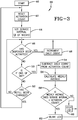
- the operational process performed by the controller 36 for indication is designated by the numeral 38, as shown in Fig. 3 .
- the process 38 has a start sequence at step 40.
- the controller 36 stores an activation count, which is provided by the RFID tag reader 28.
- the activation count represents the total number of dispenses remaining in the cartridge 14.
- controller 36 stores the service interval in weeks, which is entered from the duration dial.
- controller 36 monitors the activation switch 32 to determine whether the dispenser has been activated. When the controller 36 detects the dispenser has been activated, the controller 36 increments the daily count as shown in step 48 and then returns back to step 46. It should be noted that the daily count is initially set to zero but remains in memory for a weekly average calculation, which will be further discussed below.
- step 50 determines whether it is the end of the day.
- the controller 36 determines whether the refill has been changed at step 52.
- the controller 36 either returns to step 42 when the controller 36 detects a signal indicating product replacement or returns to step 46 if replacement has not yet occurred.
- step 50 the controller 36 proceeds to step 54 and subtracts a daily count from the activation count.
- step 56 the controller 36 calculates a weekly average by evaluating the current daily count with the daily counts of the past six days. The weekly average can be calculated even after cartridge replacement because, as stated above, the daily count remains in memory after the service interval and the activation count have been reset.
- step 58 the controller 36 compares the product of the weekly average and service interval to the activation count. If the product of the weekly average and service interval is less than the activation count, the controller 36 does not power light-emitting diode 34, as shown in step 60.
- the controller 36 sends a signal to flash the LED 34 to indicate that the dispensing material will be consumed prior to the next scheduled service, as shown at step 62. After step 62, the controller 36 then returns to step 46.
- FIG. 4-8 another embodiment of the present invention provides a dispenser 100 with an integrated service interval indicator.
- the dispenser 100 as shown in Figs. 4 and 5 , is configured to maintain a replaceable refill container 110 that carries a predetermined quantity of material, such as soap.
- a timer 120 that is monitored by a controller 150 identifies the cumulative duration in which the refill container 110 has been placed into use. Using the cumulative duration value, the controller 150 identifies the average usage of the refill container 110 to compute a remaining service interval value or optimum service interval value that identifies the remaining duration in which the refill container 110 is anticipated to remain operable.
- the dispenser 100 enables the individual charged with the replacement of the consumed or depleted refill containers to reduce the frequency by which they are monitored between their replacement, thereby saving time and resources.
- the time saved from the reduced monitoring frequency may be used to check and monitor additional dispensers that could not normally be checked by that person.
- the dispenser 100 includes the controller 150 that comprises the necessary hardware and/or software needed to carry out the functions to be discussed. Coupled to the controller 150 is a pump 200 that is in operative communication with the replaceable refill container 110, which maintains a predetermined amount of material, such as soap. An actuator 230 coupled to the controller 150 initiates a dispensing cycle of a predetermined or metered amount of material from a nozzle 240 in accordance with a shot size value stored at a memory unit 300.
- the actuator 230 may comprise a manually-actuated button, lever, or other device that when physically engaged, initiates the dispensement of material.
- the dispenser 100 may be configured to enable touch-free operation, such that the actuator 230 is configured as a proximity sensor, such as an IR (infrared) sensor, whereby the presence of the user's hand initiates the dispensing of material from the refill container 110.
- the refill container 110 may maintain any other suitable type of material, including but not limited to soap, sanitizer, lotion, or any other viscous, flowable, powder, granular substance or product. It also is foreseen that the dispensers 100 may be readily configured to dispense wipes, tablets, or other products.
- the memory unit 300 is coupled to the controller 150 and comprises non-volatile memory (NVM), volatile memory, or a combination of both.
- NVM non-volatile memory
- the memory unit 300 may be removable from the dispenser 100 so that it can be remotely programmed with various data to be discussed and then reinserted at the dispenser 100.
- the memory unit 300 may be removed from the controller 150, it may be made integral therewith as well.
- the memory unit 300 may be configured to maintain a memory that is integral with the dispenser 100 or that is removable from the dispenser 100.
- the timer 120 is also coupled to the controller 150 , which is capable of identifying the amount of time that has elapsed since the refill container 220 was inserted into the dispenser 100. As such, when the dispenser 100 is operational, the timer 120 generates a timed count value that is stored and updated at the memory unit 300. While the timer 120 is shown as being a separate component, it may be integral with the controller 150. In order to provide power in a format compatible with the operation of the dispenser, a power supply 400 is coupled to the controller 150. The power supply 400 may be configured to receive power from either a portable power source, such as a battery, or a mains power source, such as 120VAC provided by a wall outlet.
- a portable power source such as a battery
- a mains power source such as 120VAC provided by a wall outlet.
- a visual and/or audible indicator 450 is coupled to the controller 150.
- the indicator 450 comprises any suitable display or display element, such as an LED (light-emitting diode), LCD (liquid crystal display), speaker, or any other device that may provide visual indicia and/or audible prompts to indicate the remaining service interval for the refill container 220.
- a LED maintained by the dispenser 100 may generate two flashes to indicate that two weeks of product remains.
- the controller 150 is required to ascertain an initial quantity value from the refill container 110, which identifies the total amount of material in the refill container prior to its installation at the dispenser 100.
- the initial quantity value may be stored in a refill memory unit 452 maintained by the refill container 110 that is communicated to the controller 150 by an appropriate "reader" when the refill container 110 is installed at the dispenser 100.
- the memory unit 300 of the dispenser 100 may also be pre-programmed with the initial quantity value at the time of manufacture, prior to the use of the refill container 110.
- the refill memory unit 452 may comprise volatile memory, non-volatile memory, or a combination of both.
- the dispenser 100 may include a keypad 454 coupled to the controller 150 that enables an individual maintaining the dispenser 100 to manually input the initial quantity value that indicates the capacity of material maintained by the refill container 220.
- the keypad 454 may comprise suitable numeric buttons or may include predetermined quantities associated with each size of refill container 110.
- the keypad 454 may also include other key configurations as well.
- the controller 150 computes either of the remaining or the optimum service interval value which identifies the remaining operating life of the refill container 110 by processing a plurality of values that are maintained at either of the memory unit 300 and/or the controller 150, which include: the initial quantity value, the timed count value, a cumulative usage value, a current quantity value, and an average usage value.
- the initial quantity value identifies the amount of material maintained by the refill container 110 prior to its installation into the dispenser 100; the timed count value identifies the amount of time that has elapsed since the refill container 110 was installed and placed into service at the dispenser 100; the cumulative usage value is ascertained by monitoring the number of dispensing events initiated by the actuator 230 and multiplying it by the shot size associated with each dispensing event; the current quantity value identifies the amount of material that remains in the refill container when the service interval value is updated and displayed via the indicator 450; and the average usage value is derived from the division of the cumulative usage value by the timed count value, whereby the average usage value is presented in terms of material quantity per time unit.
- such values are maintained and/or processed by the controller 150 and/or memory unit 300, in the manner to be discussed, in order to compute either of the remaining or optimum service interval value for display via the indicator 450.
- an indicator 450' allows the user, such as a service technician, to visually identify the amount of material remaining in the refill container 110; the usage rate of the material dispensed from the refill container 110; and when the dispenser 100 requires service.
- the indicator 450' includes a plurality of sections, including an amount of refill remaining section 462, an amount of refill used per week section 464, and a service notification section 466.
- respective indicator groups 468 and 470 are associated therewith.
- the indicator groups 468 and 470 maintain respective illuminable identifiers 472A-E and 474A-E that are illuminated based on the use of the refill container 110. That is, identifiers 472A, 472B, 472C, 472D, and 472E, which are associated with respective values 1/8, 1/4, 1/2, 3/4, and 1, are illuminated to indicate the remaining amounts of material within the refill container 110.
- identifiers 474A, 474B, 474C, 474D, and 474E which are associated with respective usage values 1/8, 1/4, 1/2, 3/4, and 1, are illuminated in a manner that corresponds to the amount of material that is consumed by the dispenser 100 over a given period of time. That is, the indicator 450', via identifiers 474A-E, is configured to display the service interval associated with consumption of material from the refill container 110 over a given period of time, in a manner to be discussed.
- the indicator 450' may illuminate identifier 474E, associated with the value "I,” to indicate a service interval when an entire refill container 110 of material is consumed over a given period of time, or may illuminate identifiers 474D, 474C, 474B, or 474A to indicate a service interval when 3/4, 1/2, 1/4, or 1/8 of the material in the refill container 110 is used over a given period of time, such as a week for example. It should be appreciated that when a computed service interval value is not exactly equal to the usage values associated with the identifiers 474A-E, the identifier associated with a usage value 474A-E that is closest in magnitude to the computed service interval value is illuminated.
- the service notification section 466 may also maintain an illuminable identifier 480 that is illuminated when the amount of material remaining in the refill container 110 has been depleted below a predetermined level, to indicate it is in need of replacement.
- the identifier 480 may illuminate when less than 1/8 of the material in the refill container 110 remains.
- the indicator 450' may also include a test button 482 that will illuminate the illuminable identifiers 472A-E and 474A-E for a predetermined period of time, such as one minute, when it is depressed.
- the illuminable identifiers 472A-E and 474A-E may be configured to only be illuminated, when a test mode is entered upon the depression of a test button 482, although other embodiments exist where the illuminable identifiers 472A-E and 474A-E are illuminated at all times.
- the test button 482 may include an associated illuminable identifier 484 that is illuminated when the test mode is entered after the test button 482 has been depressed.
- the indicator 450' may also include a reset button 486 that is used when a new refill container 110 has been installed at the dispenser 100.
- the indicator groups 466 and 468 are set to their default position, whereby identifier 472E associated with the value "1" is illuminated to indicate the refill container 110 is full, while identifiers 474A-E are turned off.
- the depression of the reset button 486 also results in the resetting of the illuminable identifier 480 if it was previously illuminated to indicate that the previous refill container 110 was empty.
- the reset button 486 may also have an illuminable identifier 488 associated therewith that is illuminated to indicate that the reset button 486 has been depressed.
- the refill container 110 is inserted into the dispenser 100 so as to be in operative communication with the pump 200.
- the timer 120 is reset and started, in order to update the timed count value maintained by the memory unit 300, as indicated at step 512.
- the controller 150 communicates with the refill container 110 to identify the initial quantity value, which identifies the amount of material maintained in the refill container 110, as indicated at step 520.
- the initial quantity value may be input manually via the keypad 454 or is pre-programmed into the dispenser 100 during manufacturing.
- the initial quantity value is stored at the memory unit 300 prior to moving to step 540, whereby the controller 150 determines whether the actuator 230 has been engaged. If the actuator 230 has not been engaged then the process 500 remains at step 540. However, when the actuator 230 is engaged, the process 500 continues to step 550, whereupon the dispenser 100 dispenses an amount of material equal to the predetermined shot size value that is stored at the memory unit 300.
- step 560 the controller 150 increments a cumulative usage value by the predetermined shot size value. It should be appreciated that when the refill container 110 or cartridge is initially installed into the dispenser 110, the cumulative usage value is set to zero. After the cumulative usage value has been incremented, the controller 150 subtracts the cumulative usage value from the initial quantity value to obtain a current quantity value that is stored at the memory unit 300, as indicated at step 570. After the completion of step 570, the process 500 continues to step 572, where the controller 150 obtains the timed count or elapsed time value from the memory unit 300. Next, at step 580, the controller 150 computes an average usage value based on the cumulative usage value divided by the timed count value.
- the timed count value used to calculate the average usage value may be based on any time basis, such as days, weeks, months, etc.
- the process 500 continues to step 590, where the controller 150 divides the current quantity value by the average usage value to obtain the remaining service interval value.
- the computed service interval time or value is then displayed via the interval indicator 450 or 450', as indicated at step 600, and the process returns to the step of monitoring the actuator at 540 and continuing to index and update the various values through the process 500.
- the refill cartridge or container 110 may then be replaced, or, alternatively, service personnel may then schedule a service visit for near the time indicated by the service interval indicator 450. In either event, replacement of the refill container 110 initiates and resets the various counters and registers such that the process 500 may begin anew.
- the dispenser 100 may be configured to calculate and display the optimum service interval, which represents the time in which the refill container 110 needs replacing based on its complete historical usage.
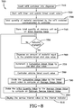
- the operational steps taken by the dispenser 100 to compute the service interval are generally referred to by the numeral 700, as shown in Fig. 8 of the drawings.
- the refill container 110 is inserted into the dispenser 100 so as to be in operative communication with the pump 200.
- the timer 120 is reset and started in order to update the timed count value maintained by the memory unit 300, as indicated at step 720.
- step 730 is performed, whereby the controller 150 communicates with the refill container 110 to identify the initial quantity value, which identifies the amount of material maintained in the refill container 110. It should also be appreciated that in embodiments where the dispenser 100 does not communicate with the refill container 110 that the initial quantity value may be input manually via the keypad 454 or is pre-programmed into the dispenser 100 during manufacturing.
- the initial quantity value is stored at the memory unit 300 prior to moving to step 750, whereby the controller 150 determines whether the actuator 230 has been engaged. If the actuator 230 has not been engaged, then the process 500 remains at step 750. However, when the actuator 230 is engaged, the process 700 continues to step 760, whereupon the dispenser 100 dispenses an amount of material equal to the predetermined shot size value that is stored at the memory unit 300.
- the controller 150 increments a cumulative usage value by the predetermined shot size value. It should be appreciated that when the refill container 110 or cartridge is initially installed into the dispenser 100, the cumulative usage value is set to zero. After the cumulative usage value has been incremented, the process 700 continues to step 780, where the controller 150 obtains the timed count value or elapsed time value from the memory unit 300. Next, at step 790, the controller 150 computes an average usage value based on the cumulative usage value divided by the timed count value. The timed count value used to calculate the average usage value may be based on any time basis, such as days, weeks, months, etc.
- step 800 the controller 150 divides the initial quantity value by the average usage value to obtain the service interval value.
- the computed optimum service interval time or value is then displayed via the interval indicator 450 or 450', as indicated at step 810, before the process 700 returns to the step 540, where the process 700 resumes the monitoring of the actuator 230.
- a dispenser maintains an integrated service interval indicator to reduce the amount of time an individual maintaining the dispenser needs to check the capacity of the refill container.
- a dispenser with an integrated service interval indicator utilizes a refill container that provides a refill memory unit, which communicates the initial quantity value to the dispenser.
- a dispenser with an integrated service interval indicator provides a keypad to enable a user to manually enter the initial quantity value associated with the refill container into the dispenser.
- An additional advantage of the present invention is that a dispenser with an integrated service interval indicator allows the individual responsible for replacing depleted refill containers to be made aware of the anticipated remaining operational life of the refill container without the need to physically open the dispenser to view the refill container, thus saving time and resources.
Landscapes
- Physics & Mathematics (AREA)
- Fluid Mechanics (AREA)
- General Physics & Mathematics (AREA)
- Analytical Chemistry (AREA)
- Chemical & Material Sciences (AREA)
- Health & Medical Sciences (AREA)
- Public Health (AREA)
- Containers And Packaging Bodies Having A Special Means To Remove Contents (AREA)
- Details Of Rigid Or Semi-Rigid Containers (AREA)
- Loading And Unloading Of Fuel Tanks Or Ships (AREA)
- Warehouses Or Storage Devices (AREA)
- Management, Administration, Business Operations System, And Electronic Commerce (AREA)
- Devices For Dispensing Beverages (AREA)
Claims (8)
- Spender (100), umfassend:einen Nachfüllbehälter (110), der eine Anfangsmenge an Material aufnimmt,eine Steuerung (150), die dazu beschaffen ist, einen Anfangs-Mengenwert zu behalten, der durch die Anfangsmenge an Material definiert wird, die vom Nachfüllbehälter (110) aufgenommen ist, wobei die Steuerung einen Zeitgeber (120) enthält,eine Anzeige (450; 450'), der mit der Steuerung (150) verbunden ist,ein Stellglied (230), das mit der Steuerung (150) verbunden ist, wobei das Stellglied (230) dazu beschaffen ist, auf einer zufälligen Basis betätigt zu werden,eine Pumpe (200), die mit der Steuerung verbunden und dazu beschaffen ist, wirksam mit dem Nachfüllbehälter (110) verbunden zu werden,dadurch gekennzeichnet, dass der Zeitgeber (120) einen zeitlich festgelegten Zählwert bewahrt, der in einem vorgegebenen Intervall aktualisiert wird, wobei der zeitlich festgelegte Zählwert dem Betrag einer Zeit entspricht, die verstrichen ist, seit der Nachfüllbehälter (110) im Spender (100) installiert und in Betrieb genommen wurde,wobei die Steuerung (150) dazu beschaffen ist, den Zeitgeber (120) zu veranlassen, mit dem Aktualisieren des zeitlich festgelegten Zählwerts derart zu beginnen, wenn der Nachfüllbehälter (110) mit der Pumpe (200) verbunden wird, dass wenn das Stellglied (230) betätigt wird, die Pumpe (200) eine vorgegebene Menge an Material entsprechend einem vorgegebenen Dosiermengenwerts aus dem Nachfüllbehälter (110) abgibt und die Steuerung (150) einen darin bewahrten kumulativen Gebrauchswert durch den Dosiermengenwert aktualisiert, unddie Steuerung (150) dazu beschaffen ist, den kumulativen Gebrauchswert durch den zeitlich festgelegten Zählwert zu teilen, um einen mittleren Gebrauchswert zu erhalten, der eine Materialmenge pro Zeiteinheit angibt, und dann den Anfangs-Mengenwert durch den mittleren Gebrauchswert zu teilen, um einen Wert für ein optimales Serviceintervall zu erhalten, der über die Anzeige (450; 450') angezeigt wird.
- Spender (100), umfassend:einen Nachfüllbehälter (110), der eine Anfangsmenge an Material aufnimmt,eine Steuerung (150), die dazu beschaffen ist, einen Anfangs-Mengenwert zu behalten, der durch die Anfangsmenge an Material definiert wird, die vom Nachfüllbehälter (110) aufgenommen ist, wobei die Steuerung einen Zeitgeber (120) enthält,eine Anzeige (450; 450'), der mit der Steuerung (150) verbunden ist,ein Stellglied (230), das mit der Steuerung (150) verbunden ist, wobei das Stellglied (230) dazu beschaffen ist, auf einer zufälligen Basis betätigt zu werden,eine Pumpe (200), die mit der Steuerung verbunden und dazu beschaffen ist, wirksam mit dem Nachfüllbehälter (110) verbunden zu werden,dadurch gekennzeichnet, dass der Zeitgeber (120) einen zeitlich festgelegten Zählwert bewahrt, der in einem vorgegebenen Intervall aktualisiert wird, wobei der zeitlich festgelegte Zählwert dem Betrag einer Zeit entspricht, die verstrichen ist, seit der Nachfüllbehälter (110) im Spender (100) installiert und in Betrieb genommen wurde,wobei die Steuerung (150) dazu beschaffen ist, den Zeitgeber (120) zu veranlassen, mit dem Aktualisieren des zeitlich festgelegten Zählwerts derart zu beginnen, wenn der Nachfüllbehälter (110) mit der Pumpe (200) verbunden wird, dass wenn das Stellglied (230) betätigt wird, die Pumpe (200) eine vorgegebene Menge an Material entsprechend einem vorgegebenen Dosiermengenwerts aus dem Nachfüllbehälter (110) abgibt und die Steuerung (150) einen darin bewahrten kumulativen Gebrauchswert durch den Dosiermengenwert aktualisiert, unddie Steuerung (150) dazu beschaffen ist, den kumulativen Gebrauchswert durch den zeitlich festgelegten Zählwert zu teilen, um einen mittleren Gebrauchswert zu erhalten, der eine Materialmenge pro Zeiteinheit angibt, dann den kumulativen Gebrauchswert vom Anfangs-Mengenwert zu subtrahieren, um einen Momentan-Mengenwert zu erhalten, und dann den Momentan-Mengenwert durch den mittleren Gebrauchswert zu teilen, um einen Wert für ein verbleibendes Serviceintervall zu erhalten, der über die Anzeige (450; 450') angezeigt wird.
- Spender (100) nach Anspruch 1 oder 2, wobei das Stellglied (230) einen Näherungssensor umfasst.
- Spender (100) nach Anspruch 1 oder 2, wobei der Nachfüllbehälter (110) eine Nachfüllspeichereinheit (452) trägt, welche den Anfangs-Mengenwert an die Steuerung (110) überträgt, wenn der Nachfüllbehälter (110) mit der Pumpe (200) verbunden wird.
- Spender (100) nach Anspruch 2, ferner umfassend ein Tastenfeld (454), das mit der Steuerung (150) verbunden ist, um den Anfangs-Mengenwert an die Steuerung (110) zu übertragen.
- Spender (100) nach Anspruch 1 oder 2, wobei die Anzeige (450') eine Vielzahl von aufhellbaren Kennungen (474A-E) umfasst, die vorgegebenen Verbrauchwerten derart zugeordnet sind, dass die aufhellbare Kennung, die dem Gebrauchswert zugeordnet ist, der in der Größenordnung dem Serviceintervall am nächsten kommt, aufgehellt wird.
- Verfahren zum Bestimmen des verbleibenden Serviceintervalls eines Nachfüllbehälters (110), umfassend:Bereitstellen eines Spenders (100) mit einer Steuerung (150) zum Steuern einer Pumpe (200), um Material aus einem Nachfüllbehälter (110) abzugeben, wobei die Steuerung (150) einen Anfangs-Mengenwert speichert, der die Angangsmenge an Material im Nachfüllbehälter (110) angibt, wobei der Spender zudem eine Anzeige (450, 450') und einen Zeitgeber (120) enthält, die mit der Steuerung (150) verbunden sind,dadurch gekennzeichnet, dass das Verfahren ferner umfasst:Veranlassen des Zeitgebers (120), einen zeitlich festgelegten Zählwert zu aktualisieren, wenn der Nachfüllbehälter (110) im Spender (100) installiert wird,Abgeben einer vorgegebenen Menge an Material auf einer zufälligen Basis aus der Pumpe (200),Identifizieren der Gesamtmenge an Material, das durch die Pumpe (200) aus dem Nachfüllbehälter (110) abgegeben wurde, um einen Gebrauchswert zu berechnen,Erzeugen eines mittleren Gebrauchswerts in der Steuerung (150) durch Dividieren des kumulativen Gebrauchswerts durch den zeitlich festgelegten Zählwert, wobei der mittlere Gebrauchswert eine Materialmenge pro Zeiteinheit angibt,Erzeugen eines Werts für ein optimales Serviceintervall in der Steuerung (150) durch Dividieren des Anfangs-Mengenwerts durch den mittleren Gebrauchswert, um die Gebrauchsbetriebszeit des Nachfüllbehälters (110) anzugeben, undAnzeigen des optimalen Serviceintervalls über die Anzeige (450, 450').
- Verfahren zum Bestimmen des verbleibenden Serviceintervalls eines Nachfüllbehälters (110), umfassend:Bereitstellen eines Spenders (100) mit einer Steuerung (150) zum Steuern einer Pumpe (200), um Material aus einem Nachfüllbehälter (110) abzugeben, wobei die Steuerung (150) einen Anfangs-Mengenwert speichert, der die Angangsmenge an Material im Nachfüllbehälter (110) angibt, wobei der Spender zudem eine Anzeige (450, 450') und einen Zeitgeber (120) enthält, die mit der Steuerung (150) verbunden sind,dadurch gekennzeichnet, dass das Verfahren ferner umfasst:Veranlassen des Zeitgebers (120), einen zeitlich festgelegten Zählwert zu aktualisieren, wenn der Nachfüllbehälter (110) im Spender (100) installiert wird,Abgeben einer vorgegebenen Menge an Material auf einer zufälligen Basis aus der Pumpe (200),Identifizieren der Gesamtmenge an Material, das durch die Pumpe (200) aus dem Nachfüllbehälter (110) abgegeben wurde, um einen Gebrauchswert zu berechnen,Erzeugen eines mittleren Gebrauchswerts in der Steuerung (150) durch Dividieren des kumulativen Gebrauchswerts durch den zeitlich festgelegten Zählwert, wobei der mittlere Gebrauchswert eine Materialmenge pro Zeiteinheit angibt,Erzeugen eines Momentan-Mengenwerts in der Steuerung (150) durch Subtrahieren des kumulativen Gebrauchswerts vom Anfangs-Mengenwert,Erzeugen eines Werts für ein verbleibendes Serviceintervall in der Steuerung (150) durch Dividieren des Momentan-Mengenwerts durch den mittleren Gebrauchswert, um die Gebrauchsbetriebszeit des Nachfüllbehälters (110) anzugeben, undAnzeigen des verbleibenden Serviceintervalls über die Anzeige (450, 450').
Priority Applications (1)
| Application Number | Priority Date | Filing Date | Title |
|---|---|---|---|
| EP20177059.1A EP3785806B1 (de) | 2009-04-17 | 2010-04-15 | Verfahren und vorrichtung zur anzeige des künftigen bedarfs eines produktersatzes mit willkürlicher abgabe |
Applications Claiming Priority (1)
| Application Number | Priority Date | Filing Date | Title |
|---|---|---|---|
| US12/425,444 US9555429B2 (en) | 2007-11-14 | 2009-04-17 | Method and device for indicating future need for product replacement of random-use dispensing |
Related Child Applications (1)
| Application Number | Title | Priority Date | Filing Date |
|---|---|---|---|
| EP20177059.1A Division EP3785806B1 (de) | 2009-04-17 | 2010-04-15 | Verfahren und vorrichtung zur anzeige des künftigen bedarfs eines produktersatzes mit willkürlicher abgabe |
Publications (3)
| Publication Number | Publication Date |
|---|---|
| EP2241377A2 EP2241377A2 (de) | 2010-10-20 |
| EP2241377A3 EP2241377A3 (de) | 2013-06-12 |
| EP2241377B1 true EP2241377B1 (de) | 2020-06-03 |
Family
ID=42245036
Family Applications (2)
| Application Number | Title | Priority Date | Filing Date |
|---|---|---|---|
| EP20177059.1A Active EP3785806B1 (de) | 2009-04-17 | 2010-04-15 | Verfahren und vorrichtung zur anzeige des künftigen bedarfs eines produktersatzes mit willkürlicher abgabe |
| EP10160053.4A Active EP2241377B1 (de) | 2009-04-17 | 2010-04-15 | Verfahren und Vorrichtung zur Anzeige des künftigen Bedarfs eines Produktersatzes mit willkürlicher Abgabe |
Family Applications Before (1)
| Application Number | Title | Priority Date | Filing Date |
|---|---|---|---|
| EP20177059.1A Active EP3785806B1 (de) | 2009-04-17 | 2010-04-15 | Verfahren und vorrichtung zur anzeige des künftigen bedarfs eines produktersatzes mit willkürlicher abgabe |
Country Status (9)
| Country | Link |
|---|---|
| US (3) | US9555429B2 (de) |
| EP (2) | EP3785806B1 (de) |
| JP (3) | JP5711469B2 (de) |
| KR (1) | KR20100115318A (de) |
| CN (1) | CN101863348B (de) |
| AU (1) | AU2010201496A1 (de) |
| BR (1) | BRPI1001169A2 (de) |
| CA (1) | CA2700026C (de) |
| TW (2) | TW201533431A (de) |
Families Citing this family (60)
| Publication number | Priority date | Publication date | Assignee | Title |
|---|---|---|---|---|
| FR2907654B1 (fr) | 2006-10-31 | 2010-01-29 | Georgia Pacific France | Procede, dispositif de fabrication et rouleaux associes formes de feuilles a decoupes et predecoupes alternees |
| US11297984B2 (en) | 2006-10-31 | 2022-04-12 | Gpcp Ip Holdings Llc | Automatic napkin dispenser |
| EP2294544A4 (de) | 2008-04-30 | 2013-01-16 | Ecolab Inc | Validierte gesundheitsversorgungs-reinigungs- und desinfektionspraktiken |
| US8639527B2 (en) | 2008-04-30 | 2014-01-28 | Ecolab Usa Inc. | Validated healthcare cleaning and sanitizing practices |
| US8600547B2 (en) | 2008-08-22 | 2013-12-03 | Georgia-Pacific Consumer Products Lp | Sheet product dispenser and method of operation |
| US7996108B2 (en) | 2008-08-22 | 2011-08-09 | Georgia-Pacific Consumer Products Lp | Sheet product dispenser and method of operation |
| US8240508B2 (en) * | 2008-12-29 | 2012-08-14 | Gojo Industries, Inc. | Low cost radio frequency identification (RFID) dispensing systems |
| USRE48951E1 (en) | 2015-08-05 | 2022-03-01 | Ecolab Usa Inc. | Hand hygiene compliance monitoring |
| EP2441063B1 (de) | 2009-06-12 | 2015-03-11 | Ecolab USA Inc. | Handhygiene-konformitätsüberwachung |
| US8622242B2 (en) * | 2010-04-16 | 2014-01-07 | Gojo Industries, Inc. | Taggant keying system for dispensing systems |
| WO2011149884A2 (en) | 2010-05-24 | 2011-12-01 | Georgia-Pacific Consumer Products Lp | Hand hygiene compliance system |
| US8427323B2 (en) | 2010-06-25 | 2013-04-23 | Pibed Limited | Monitoring system |
| WO2012064718A2 (en) | 2010-11-08 | 2012-05-18 | Georgia-Pacific Consumer Products Lp | Hand hygiene compliance monitoring system |
| US20140210620A1 (en) | 2013-01-25 | 2014-07-31 | Ultraclenz Llc | Wireless communication for dispenser beacons |
| JP6003040B2 (ja) * | 2011-10-31 | 2016-10-05 | キヤノンマーケティングジャパン株式会社 | 滅菌装置、滅菌装置の制御方法、プログラム |
| JP6003039B2 (ja) * | 2011-10-31 | 2016-10-05 | キヤノンマーケティングジャパン株式会社 | 滅菌装置、滅菌装置の制御方法、プログラム |
| US8991649B2 (en) | 2012-01-05 | 2015-03-31 | Gojo Industries, Inc. | Keyed dispensing systems and related methods |
| US10383489B2 (en) | 2012-02-10 | 2019-08-20 | Gpcp Ip Holdings Llc | Automatic napkin dispenser |
| US9340337B2 (en) | 2012-05-01 | 2016-05-17 | Ecolab Usa Inc. | Dispenser with lockable pushbutton |
| US8851331B2 (en) | 2012-05-04 | 2014-10-07 | Ecolab Usa Inc. | Fluid dispensers with adjustable dosing |
| US8991655B2 (en) | 2013-02-15 | 2015-03-31 | Ecolab Usa Inc. | Fluid dispensers with increased mechanical advantage |
| US9604811B2 (en) | 2013-10-01 | 2017-03-28 | Georgia-Pacific Consumer Products Lp | Automatic paper product dispenser with data collection and method |
| CN103784072B (zh) * | 2014-01-23 | 2016-01-13 | 金红叶纸业集团有限公司 | 分配器及应用该分配器的系统 |
| JP2015190878A (ja) * | 2014-03-28 | 2015-11-02 | 百合香 石山 | トイレットペーパーメータ及びトイレットペーパーホルダ |
| US10130221B2 (en) | 2015-01-23 | 2018-11-20 | Gpcp Ip Holdings Llc | Optimizing a dispensing parameter of a product dispenser based on product usage data |
| US10459460B2 (en) | 2015-11-16 | 2019-10-29 | Gojo Industries, Inc. | Product reservoir validation system |
| US11395566B2 (en) | 2016-04-11 | 2022-07-26 | Gpcp Ip Holdings Llc | Sheet product dispenser |
| US11412900B2 (en) | 2016-04-11 | 2022-08-16 | Gpcp Ip Holdings Llc | Sheet product dispenser with motor operation sensing |
| AU2016404262B2 (en) * | 2016-04-29 | 2023-03-30 | Kimberly-Clark Worldwide, Inc. | Dispensing system |
| US10732021B2 (en) * | 2016-05-17 | 2020-08-04 | Gojo Industries, Inc. | Method and apparatus for calibrating remaining doses in a refillable dispenser |
| US9677923B1 (en) * | 2016-05-23 | 2017-06-13 | Thirsti Ltd | Universal device for monitoring and reporting fluid consumption and method using same |
| CA2968112C (en) * | 2016-05-26 | 2025-09-23 | Op-Hygiene Ip Gmbh | MAINTENANCE OF A DISPENSER INTENDED FOR AN INSTALLATION WITH MULTIPLE BATHROOMS |
| AU2017331740B2 (en) * | 2016-09-21 | 2023-03-30 | Smart Wave Technologies Inc. | Universal dispenser monitor |
| GB2557242A (en) * | 2016-12-01 | 2018-06-20 | Deb Ip Ltd | A consumables monitoring system |
| CN110383355B (zh) | 2017-03-07 | 2021-08-27 | 埃科莱布美国股份有限公司 | 用于手部卫生分配器的监测模块 |
| US10961107B2 (en) | 2017-03-14 | 2021-03-30 | Gojo Industries, Inc. | Refilling systems, refillable containers and method for refilling containers |
| CN114947592A (zh) | 2017-05-10 | 2022-08-30 | Gpcp知识产权控股有限责任公司 | 自动纸产品分配器及相关联的方法 |
| US10874265B2 (en) | 2017-05-10 | 2020-12-29 | Gpcp Ip Holdings Llc | Sheet product level sensor calibration and indication systems and methods |
| JP7117830B2 (ja) * | 2017-07-14 | 2022-08-15 | 花王株式会社 | ディスペンサ |
| US11181413B2 (en) | 2017-08-29 | 2021-11-23 | Gpcp Ip Holdings Llc | Product level detection apparatuses and systems for fluid dispensers |
| US10529219B2 (en) | 2017-11-10 | 2020-01-07 | Ecolab Usa Inc. | Hand hygiene compliance monitoring |
| USD886245S1 (en) | 2018-04-26 | 2020-06-02 | Bradley Fixtures Corporation | Dispenser |
| USD886240S1 (en) | 2018-04-26 | 2020-06-02 | Bradley Fixtures Corporation | Faucet and soap dispenser set |
| WO2019210184A1 (en) * | 2018-04-27 | 2019-10-31 | Rpg Imx Llc | Systems and methods for dispensing components for customized compositions and formulations |
| JP2020026984A (ja) * | 2018-08-09 | 2020-02-20 | パイオニア株式会社 | 薬剤使用状態検出装置 |
| CN109567658A (zh) * | 2018-10-29 | 2019-04-05 | 杭州数策指今科技有限公司 | 智能三出纸系统 |
| EP3900307A1 (de) | 2018-12-20 | 2021-10-27 | Ecolab USA, Inc. | Bidirektionale netzwerkkommunikation mit adaptiver route |
| US11617478B2 (en) | 2019-10-09 | 2023-04-04 | Gpcp Ip Holdings Llc | Systems and methods for product level tracking of sheet product rolls |
| DE102019135750A1 (de) * | 2019-12-23 | 2021-06-24 | WELLGO Gerätetechnik GmbH | Vorrichtung und Verfahren zur Abgabe eines Tuchs oder einer Reinigungsflüssigkeit |
| US11612277B2 (en) * | 2020-05-14 | 2023-03-28 | Gojo Industries, Inc. | Dispensers and dispenser systems for securely controlling a plurality of dose sizes |
| CN115697154B (zh) | 2020-07-02 | 2025-09-19 | 易希提卫生与保健公司 | 包括分配器和可更换液体容器的分配器系统 |
| US12458181B2 (en) | 2020-07-02 | 2025-11-04 | Essity Hygiene And Health Aktiebolag | Insert module in a dispenser |
| CN115697155B (zh) | 2020-07-02 | 2023-10-24 | 易希提卫生与保健公司 | 包括可更换的液体容器的分配器 |
| US11641984B2 (en) * | 2020-07-07 | 2023-05-09 | Henkel Ag & Co. Kgaa | Commodity dispenser system with inventory monitor and use-based replenishment features |
| CA3086861A1 (en) * | 2020-07-14 | 2022-01-14 | Op-Hygiene Ip Gmbh | Fluid dispenser with thermometer |
| US12507835B2 (en) | 2021-03-23 | 2025-12-30 | Kimberly-Clark Worldwide, Inc. | Reservoir assembly for a liquid product dispenser |
| US11744413B2 (en) | 2021-10-07 | 2023-09-05 | Deb Ip Limited | Dispenser assembly |
| US20230152063A1 (en) * | 2021-11-17 | 2023-05-18 | Crystal, Inc. | Incapacitating Chemical Agent Dispersal Using a Portable Electronic Device |
| CN114567630B (zh) * | 2022-04-29 | 2022-07-19 | 南京信思顺信息技术有限公司 | 一种基于流程引擎的智能表单生成方法 |
| US12515829B2 (en) * | 2023-12-15 | 2026-01-06 | Express Scripts Strategic Development, Inc. | Medication tracking system in a pharmacy |
Family Cites Families (31)
| Publication number | Priority date | Publication date | Assignee | Title |
|---|---|---|---|---|
| US4782451A (en) * | 1984-11-30 | 1988-11-01 | Union Carbide Corporation | Process for maintaining liquid supply |
| US4830791A (en) | 1988-02-29 | 1989-05-16 | Scentex, Inc. | Odor control device |
| US5301873A (en) | 1990-03-26 | 1994-04-12 | Kold Ban International | Low fluid indicator for pressurized canister |
| JPH04174616A (ja) * | 1990-07-11 | 1992-06-22 | Toto Ltd | 水石けん供給装置 |
| US5249718A (en) | 1992-03-16 | 1993-10-05 | Technical Concepts | Automatic pump-type spray dispenser |
| US5772074A (en) | 1995-03-31 | 1998-06-30 | Waterbury Companies, Inc. | Device and method for indicating the dispensing of a predetermined amount of a material |
| US5884808A (en) * | 1997-08-21 | 1999-03-23 | Technical Concepts, L.P. | Material dispensing method and apparatus having display feature |
| US5966753A (en) * | 1997-12-31 | 1999-10-19 | Sloan Valve Company | Method and apparatus for properly sequenced hand washing |
| US6404837B1 (en) | 1998-06-11 | 2002-06-11 | Ecolab, Inc. | Usage competent hand soap dispenser with data collection and display capabilities |
| US6467651B1 (en) | 1999-09-15 | 2002-10-22 | Technical Concepts, L.P. | System and method for dispensing soap |
| US6651851B2 (en) | 1999-09-15 | 2003-11-25 | Technical Concepts, Llc | System and method for dispensing soap |
| AU7580600A (en) | 1999-09-15 | 2001-04-17 | Technical Concepts, L.P. | System and method for programmably dispensing material |
| US6267297B1 (en) | 1999-10-12 | 2001-07-31 | Waterbury Companies, Inc. | Programmable dispenser |
| US6727818B1 (en) | 1999-10-29 | 2004-04-27 | Hill-Rom Services, Inc. | Hygiene monitoring system |
| EP1252400A4 (de) | 2000-02-04 | 2005-07-06 | Waterbury Co Inc | Intelligentes anfragegerichtetes spendesystem |
| JP4305593B2 (ja) | 2000-07-17 | 2009-07-29 | ソニー株式会社 | データ記録再生方法および装置、データ記録装置および方法 |
| JP2002143022A (ja) * | 2000-11-09 | 2002-05-21 | Saraya Kk | 薬液供給装置の薬液残量監視装置および監視システム |
| BR0208026A (pt) * | 2001-03-14 | 2004-02-25 | Johnson Diversey Inc | Purificador de ar automático com um intervalo de distribuição dinamicamente variável |
| US6572318B2 (en) * | 2001-04-30 | 2003-06-03 | Hewlett-Packard Development Co., Lp | Managing bookbinding consumables |
| US7032818B2 (en) * | 2001-07-03 | 2006-04-25 | Nestec S.A. | Method and system of setting and/or controlling of a food product dispensing machine using a tag-type communication device |
| KR20100105906A (ko) * | 2002-07-19 | 2010-09-30 | 엔테그리스, 아이엔씨. | 유체유동측정 및 비례유체유동 제어장치 |
| GB2392440B (en) | 2002-08-30 | 2004-11-03 | Vectair Systems Ltd | Programmable dispenser |
| EP1407790A1 (de) | 2002-10-10 | 2004-04-14 | Spy Marketing Sdn. Bhd. | Vorrichtung mit verbesserter Dispensierung von olfaktorisch stimulierenden Materialien |
| US7009519B2 (en) | 2002-11-21 | 2006-03-07 | S.C. Johnson & Sons, Inc. | Product dispensing controlled by RFID tags |
| US7242307B1 (en) | 2003-10-20 | 2007-07-10 | Cognetive Systems Incorporated | System for monitoring hygiene appliances |
| US7783380B2 (en) | 2003-12-31 | 2010-08-24 | Kimberly-Clark Worldwide, Inc. | System and method for measuring, monitoring and controlling washroom dispensers and products |
| US7187282B2 (en) * | 2004-09-09 | 2007-03-06 | Invisa, Inc | Digital capacitive sensing device for security and safety applications |
| US7621426B2 (en) | 2004-12-15 | 2009-11-24 | Joseph Kanfer | Electronically keyed dispensing systems and related methods utilizing near field frequency response |
| US7207164B2 (en) * | 2005-05-10 | 2007-04-24 | Deere & Company | Header hydraulic float suspension |
| US7895257B2 (en) | 2006-02-21 | 2011-02-22 | University Of Florida Research Foundation, Inc. | Modular platform enabling heterogeneous devices, sensors and actuators to integrate automatically into heterogeneous networks |
| US20080185395A1 (en) | 2007-02-01 | 2008-08-07 | Allegheny-Singer Research Institute | Dispenser and method |
-
2009
- 2009-04-17 US US12/425,444 patent/US9555429B2/en active Active
-
2010
- 2010-04-15 EP EP20177059.1A patent/EP3785806B1/de active Active
- 2010-04-15 CA CA2700026A patent/CA2700026C/en active Active
- 2010-04-15 AU AU2010201496A patent/AU2010201496A1/en not_active Abandoned
- 2010-04-15 EP EP10160053.4A patent/EP2241377B1/de active Active
- 2010-04-16 KR KR1020100035109A patent/KR20100115318A/ko not_active Ceased
- 2010-04-16 TW TW104104046A patent/TW201533431A/zh unknown
- 2010-04-16 BR BRPI1001169-2A patent/BRPI1001169A2/pt not_active IP Right Cessation
- 2010-04-16 CN CN201010149930.5A patent/CN101863348B/zh not_active Expired - Fee Related
- 2010-04-16 JP JP2010094994A patent/JP5711469B2/ja not_active Expired - Fee Related
- 2010-04-16 TW TW099111999A patent/TWI481823B/zh active
-
2015
- 2015-03-06 JP JP2015044862A patent/JP5964474B2/ja not_active Expired - Fee Related
-
2016
- 2016-01-29 JP JP2016015839A patent/JP6225198B2/ja not_active Expired - Fee Related
-
2017
- 2017-01-23 US US15/412,758 patent/US10545044B2/en active Active
-
2020
- 2020-01-27 US US16/773,981 patent/US11118955B2/en active Active
Non-Patent Citations (1)
| Title |
|---|
| None * |
Also Published As
| Publication number | Publication date |
|---|---|
| EP2241377A3 (de) | 2013-06-12 |
| TW201102624A (en) | 2011-01-16 |
| US9555429B2 (en) | 2017-01-31 |
| US20170131130A1 (en) | 2017-05-11 |
| JP5711469B2 (ja) | 2015-04-30 |
| TW201533431A (zh) | 2015-09-01 |
| JP6225198B2 (ja) | 2017-11-01 |
| JP2015154937A (ja) | 2015-08-27 |
| US10545044B2 (en) | 2020-01-28 |
| US20200158552A1 (en) | 2020-05-21 |
| JP2016144638A (ja) | 2016-08-12 |
| JP2010246932A (ja) | 2010-11-04 |
| CA2700026A1 (en) | 2010-10-17 |
| JP5964474B2 (ja) | 2016-08-03 |
| TWI481823B (zh) | 2015-04-21 |
| EP3785806A1 (de) | 2021-03-03 |
| EP3785806B1 (de) | 2025-09-10 |
| AU2010201496A1 (en) | 2010-11-04 |
| CA2700026C (en) | 2017-08-22 |
| BRPI1001169A2 (pt) | 2011-07-26 |
| CN101863348A (zh) | 2010-10-20 |
| CN101863348B (zh) | 2014-04-23 |
| EP2241377A2 (de) | 2010-10-20 |
| KR20100115318A (ko) | 2010-10-27 |
| US20090204256A1 (en) | 2009-08-13 |
| US11118955B2 (en) | 2021-09-14 |
Similar Documents
| Publication | Publication Date | Title |
|---|---|---|
| US11118955B2 (en) | Method and device for indicating future need for product replacement of random-use dispensing | |
| US20090125424A1 (en) | Method and device for indicating future need for product replacement of random use dispensing | |
| EP3939482B1 (de) | Flüssigkeitsspender mit thermometer | |
| US11971286B2 (en) | Method and device for indicating future need for product replacement of random-use dispensing | |
| AU2013201100A1 (en) | Method and device for indicating future need for product replacement of random-use dispensing | |
| AU2018241067B2 (en) | Method and Device for Indicating Future Need for Product Replacement of Random-Use Dispensing | |
| HK1143777A (en) | Method and device for indicating future need for product replacement of random-use dispensing | |
| GB2392439A (en) | Programmable dispenser | |
| GB2392438A (en) | Programmable dispenser | |
| GB2392440A (en) | Programmable dispenser | |
| HK1129726A (en) | Method and device for indicating future need for product replacement of random use dispensing |
Legal Events
| Date | Code | Title | Description |
|---|---|---|---|
| PUAI | Public reference made under article 153(3) epc to a published international application that has entered the european phase |
Free format text: ORIGINAL CODE: 0009012 |
|
| AK | Designated contracting states |
Kind code of ref document: A2 Designated state(s): AT BE BG CH CY CZ DE DK EE ES FI FR GB GR HR HU IE IS IT LI LT LU LV MC MK MT NL NO PL PT RO SE SI SK SM TR |
|
| AX | Request for extension of the european patent |
Extension state: AL BA ME RS |
|
| REG | Reference to a national code |
Ref country code: HK Ref legal event code: DE Ref document number: 1143777 Country of ref document: HK |
|
| PUAL | Search report despatched |
Free format text: ORIGINAL CODE: 0009013 |
|
| AK | Designated contracting states |
Kind code of ref document: A3 Designated state(s): AT BE BG CH CY CZ DE DK EE ES FI FR GB GR HR HU IE IS IT LI LT LU LV MC MK MT NL NO PL PT RO SE SI SK SM TR |
|
| AX | Request for extension of the european patent |
Extension state: AL BA ME RS |
|
| RIC1 | Information provided on ipc code assigned before grant |
Ipc: G01F 13/00 20060101ALI20130508BHEP Ipc: B05B 12/00 20060101AFI20130508BHEP Ipc: G01F 15/06 20060101ALI20130508BHEP Ipc: B05B 11/00 20060101ALN20130508BHEP Ipc: B05B 12/08 20060101ALI20130508BHEP |
|
| 17P | Request for examination filed |
Effective date: 20131126 |
|
| RBV | Designated contracting states (corrected) |
Designated state(s): AT BE BG CH CY CZ DE DK EE ES FI FR GB GR HR HU IE IS IT LI LT LU LV MC MK MT NL NO PL PT RO SE SI SK SM TR |
|
| STAA | Information on the status of an ep patent application or granted ep patent |
Free format text: STATUS: EXAMINATION IS IN PROGRESS |
|
| 17Q | First examination report despatched |
Effective date: 20161214 |
|
| REG | Reference to a national code |
Ref country code: HK Ref legal event code: WD Ref document number: 1143777 Country of ref document: HK |
|
| GRAP | Despatch of communication of intention to grant a patent |
Free format text: ORIGINAL CODE: EPIDOSNIGR1 |
|
| STAA | Information on the status of an ep patent application or granted ep patent |
Free format text: STATUS: GRANT OF PATENT IS INTENDED |
|
| RIC1 | Information provided on ipc code assigned before grant |
Ipc: B05B 12/00 20180101AFI20191112BHEP Ipc: B05B 11/00 20060101ALN20191112BHEP Ipc: B05B 12/08 20060101ALI20191112BHEP Ipc: G01F 15/06 20060101ALI20191112BHEP Ipc: A47K 5/12 20060101ALI20191112BHEP Ipc: G01F 13/00 20060101ALI20191112BHEP |
|
| INTG | Intention to grant announced |
Effective date: 20191213 |
|
| GRAS | Grant fee paid |
Free format text: ORIGINAL CODE: EPIDOSNIGR3 |
|
| GRAA | (expected) grant |
Free format text: ORIGINAL CODE: 0009210 |
|
| STAA | Information on the status of an ep patent application or granted ep patent |
Free format text: STATUS: THE PATENT HAS BEEN GRANTED |
|
| AK | Designated contracting states |
Kind code of ref document: B1 Designated state(s): AT BE BG CH CY CZ DE DK EE ES FI FR GB GR HR HU IE IS IT LI LT LU LV MC MK MT NL NO PL PT RO SE SI SK SM TR |
|
| REG | Reference to a national code |
Ref country code: GB Ref legal event code: FG4D |
|
| REG | Reference to a national code |
Ref country code: CH Ref legal event code: EP Ref country code: AT Ref legal event code: REF Ref document number: 1276480 Country of ref document: AT Kind code of ref document: T Effective date: 20200615 |
|
| REG | Reference to a national code |
Ref country code: DE Ref legal event code: R096 Ref document number: 602010064505 Country of ref document: DE |
|
| REG | Reference to a national code |
Ref country code: LT Ref legal event code: MG4D |
|
| PG25 | Lapsed in a contracting state [announced via postgrant information from national office to epo] |
Ref country code: SE Free format text: LAPSE BECAUSE OF FAILURE TO SUBMIT A TRANSLATION OF THE DESCRIPTION OR TO PAY THE FEE WITHIN THE PRESCRIBED TIME-LIMIT Effective date: 20200603 Ref country code: LT Free format text: LAPSE BECAUSE OF FAILURE TO SUBMIT A TRANSLATION OF THE DESCRIPTION OR TO PAY THE FEE WITHIN THE PRESCRIBED TIME-LIMIT Effective date: 20200603 Ref country code: FI Free format text: LAPSE BECAUSE OF FAILURE TO SUBMIT A TRANSLATION OF THE DESCRIPTION OR TO PAY THE FEE WITHIN THE PRESCRIBED TIME-LIMIT Effective date: 20200603 Ref country code: NO Free format text: LAPSE BECAUSE OF FAILURE TO SUBMIT A TRANSLATION OF THE DESCRIPTION OR TO PAY THE FEE WITHIN THE PRESCRIBED TIME-LIMIT Effective date: 20200903 Ref country code: GR Free format text: LAPSE BECAUSE OF FAILURE TO SUBMIT A TRANSLATION OF THE DESCRIPTION OR TO PAY THE FEE WITHIN THE PRESCRIBED TIME-LIMIT Effective date: 20200904 |
|
| REG | Reference to a national code |
Ref country code: NL Ref legal event code: MP Effective date: 20200603 |
|
| PG25 | Lapsed in a contracting state [announced via postgrant information from national office to epo] |
Ref country code: BG Free format text: LAPSE BECAUSE OF FAILURE TO SUBMIT A TRANSLATION OF THE DESCRIPTION OR TO PAY THE FEE WITHIN THE PRESCRIBED TIME-LIMIT Effective date: 20200903 Ref country code: HR Free format text: LAPSE BECAUSE OF FAILURE TO SUBMIT A TRANSLATION OF THE DESCRIPTION OR TO PAY THE FEE WITHIN THE PRESCRIBED TIME-LIMIT Effective date: 20200603 Ref country code: LV Free format text: LAPSE BECAUSE OF FAILURE TO SUBMIT A TRANSLATION OF THE DESCRIPTION OR TO PAY THE FEE WITHIN THE PRESCRIBED TIME-LIMIT Effective date: 20200603 |
|
| REG | Reference to a national code |
Ref country code: AT Ref legal event code: MK05 Ref document number: 1276480 Country of ref document: AT Kind code of ref document: T Effective date: 20200603 |
|
| PG25 | Lapsed in a contracting state [announced via postgrant information from national office to epo] |
Ref country code: NL Free format text: LAPSE BECAUSE OF FAILURE TO SUBMIT A TRANSLATION OF THE DESCRIPTION OR TO PAY THE FEE WITHIN THE PRESCRIBED TIME-LIMIT Effective date: 20200603 |
|
| PG25 | Lapsed in a contracting state [announced via postgrant information from national office to epo] |
Ref country code: IT Free format text: LAPSE BECAUSE OF FAILURE TO SUBMIT A TRANSLATION OF THE DESCRIPTION OR TO PAY THE FEE WITHIN THE PRESCRIBED TIME-LIMIT Effective date: 20200603 Ref country code: RO Free format text: LAPSE BECAUSE OF FAILURE TO SUBMIT A TRANSLATION OF THE DESCRIPTION OR TO PAY THE FEE WITHIN THE PRESCRIBED TIME-LIMIT Effective date: 20200603 Ref country code: PT Free format text: LAPSE BECAUSE OF FAILURE TO SUBMIT A TRANSLATION OF THE DESCRIPTION OR TO PAY THE FEE WITHIN THE PRESCRIBED TIME-LIMIT Effective date: 20201006 Ref country code: CZ Free format text: LAPSE BECAUSE OF FAILURE TO SUBMIT A TRANSLATION OF THE DESCRIPTION OR TO PAY THE FEE WITHIN THE PRESCRIBED TIME-LIMIT Effective date: 20200603 Ref country code: EE Free format text: LAPSE BECAUSE OF FAILURE TO SUBMIT A TRANSLATION OF THE DESCRIPTION OR TO PAY THE FEE WITHIN THE PRESCRIBED TIME-LIMIT Effective date: 20200603 Ref country code: SM Free format text: LAPSE BECAUSE OF FAILURE TO SUBMIT A TRANSLATION OF THE DESCRIPTION OR TO PAY THE FEE WITHIN THE PRESCRIBED TIME-LIMIT Effective date: 20200603 Ref country code: AT Free format text: LAPSE BECAUSE OF FAILURE TO SUBMIT A TRANSLATION OF THE DESCRIPTION OR TO PAY THE FEE WITHIN THE PRESCRIBED TIME-LIMIT Effective date: 20200603 Ref country code: ES Free format text: LAPSE BECAUSE OF FAILURE TO SUBMIT A TRANSLATION OF THE DESCRIPTION OR TO PAY THE FEE WITHIN THE PRESCRIBED TIME-LIMIT Effective date: 20200603 |
|
| PG25 | Lapsed in a contracting state [announced via postgrant information from national office to epo] |
Ref country code: SK Free format text: LAPSE BECAUSE OF FAILURE TO SUBMIT A TRANSLATION OF THE DESCRIPTION OR TO PAY THE FEE WITHIN THE PRESCRIBED TIME-LIMIT Effective date: 20200603 Ref country code: PL Free format text: LAPSE BECAUSE OF FAILURE TO SUBMIT A TRANSLATION OF THE DESCRIPTION OR TO PAY THE FEE WITHIN THE PRESCRIBED TIME-LIMIT Effective date: 20200603 Ref country code: IS Free format text: LAPSE BECAUSE OF FAILURE TO SUBMIT A TRANSLATION OF THE DESCRIPTION OR TO PAY THE FEE WITHIN THE PRESCRIBED TIME-LIMIT Effective date: 20201003 |
|
| REG | Reference to a national code |
Ref country code: DE Ref legal event code: R097 Ref document number: 602010064505 Country of ref document: DE |
|
| PLBE | No opposition filed within time limit |
Free format text: ORIGINAL CODE: 0009261 |
|
| STAA | Information on the status of an ep patent application or granted ep patent |
Free format text: STATUS: NO OPPOSITION FILED WITHIN TIME LIMIT |
|
| PG25 | Lapsed in a contracting state [announced via postgrant information from national office to epo] |
Ref country code: DK Free format text: LAPSE BECAUSE OF FAILURE TO SUBMIT A TRANSLATION OF THE DESCRIPTION OR TO PAY THE FEE WITHIN THE PRESCRIBED TIME-LIMIT Effective date: 20200603 |
|
| 26N | No opposition filed |
Effective date: 20210304 |
|
| PG25 | Lapsed in a contracting state [announced via postgrant information from national office to epo] |
Ref country code: SI Free format text: LAPSE BECAUSE OF FAILURE TO SUBMIT A TRANSLATION OF THE DESCRIPTION OR TO PAY THE FEE WITHIN THE PRESCRIBED TIME-LIMIT Effective date: 20200603 |
|
| PG25 | Lapsed in a contracting state [announced via postgrant information from national office to epo] |
Ref country code: MC Free format text: LAPSE BECAUSE OF FAILURE TO SUBMIT A TRANSLATION OF THE DESCRIPTION OR TO PAY THE FEE WITHIN THE PRESCRIBED TIME-LIMIT Effective date: 20200603 |
|
| PG25 | Lapsed in a contracting state [announced via postgrant information from national office to epo] |
Ref country code: LU Free format text: LAPSE BECAUSE OF NON-PAYMENT OF DUE FEES Effective date: 20210415 |
|
| REG | Reference to a national code |
Ref country code: BE Ref legal event code: MM Effective date: 20210430 |
|
| PG25 | Lapsed in a contracting state [announced via postgrant information from national office to epo] |
Ref country code: CH Free format text: LAPSE BECAUSE OF NON-PAYMENT OF DUE FEES Effective date: 20210430 Ref country code: LI Free format text: LAPSE BECAUSE OF NON-PAYMENT OF DUE FEES Effective date: 20210430 |
|
| PG25 | Lapsed in a contracting state [announced via postgrant information from national office to epo] |
Ref country code: IE Free format text: LAPSE BECAUSE OF NON-PAYMENT OF DUE FEES Effective date: 20210415 |
|
| PG25 | Lapsed in a contracting state [announced via postgrant information from national office to epo] |
Ref country code: BE Free format text: LAPSE BECAUSE OF NON-PAYMENT OF DUE FEES Effective date: 20210430 |
|
| PG25 | Lapsed in a contracting state [announced via postgrant information from national office to epo] |
Ref country code: HU Free format text: LAPSE BECAUSE OF FAILURE TO SUBMIT A TRANSLATION OF THE DESCRIPTION OR TO PAY THE FEE WITHIN THE PRESCRIBED TIME-LIMIT; INVALID AB INITIO Effective date: 20100415 Ref country code: CY Free format text: LAPSE BECAUSE OF FAILURE TO SUBMIT A TRANSLATION OF THE DESCRIPTION OR TO PAY THE FEE WITHIN THE PRESCRIBED TIME-LIMIT Effective date: 20200603 |
|
| P01 | Opt-out of the competence of the unified patent court (upc) registered |
Effective date: 20230512 |
|
| PG25 | Lapsed in a contracting state [announced via postgrant information from national office to epo] |
Ref country code: MK Free format text: LAPSE BECAUSE OF FAILURE TO SUBMIT A TRANSLATION OF THE DESCRIPTION OR TO PAY THE FEE WITHIN THE PRESCRIBED TIME-LIMIT Effective date: 20200603 |
|
| PG25 | Lapsed in a contracting state [announced via postgrant information from national office to epo] |
Ref country code: TR Free format text: LAPSE BECAUSE OF FAILURE TO SUBMIT A TRANSLATION OF THE DESCRIPTION OR TO PAY THE FEE WITHIN THE PRESCRIBED TIME-LIMIT Effective date: 20200603 |
|
| PG25 | Lapsed in a contracting state [announced via postgrant information from national office to epo] |
Ref country code: MT Free format text: LAPSE BECAUSE OF FAILURE TO SUBMIT A TRANSLATION OF THE DESCRIPTION OR TO PAY THE FEE WITHIN THE PRESCRIBED TIME-LIMIT Effective date: 20200603 |
|
| PGFP | Annual fee paid to national office [announced via postgrant information from national office to epo] |
Ref country code: DE Payment date: 20250429 Year of fee payment: 16 |
|
| PGFP | Annual fee paid to national office [announced via postgrant information from national office to epo] |
Ref country code: GB Payment date: 20250428 Year of fee payment: 16 |
|
| PGFP | Annual fee paid to national office [announced via postgrant information from national office to epo] |
Ref country code: FR Payment date: 20250425 Year of fee payment: 16 |