EP2240905B1 - Verstreute geometrie für hochauflösende videoverarbeitung - Google Patents
Verstreute geometrie für hochauflösende videoverarbeitung Download PDFInfo
- Publication number
- EP2240905B1 EP2240905B1 EP08719873A EP08719873A EP2240905B1 EP 2240905 B1 EP2240905 B1 EP 2240905B1 EP 08719873 A EP08719873 A EP 08719873A EP 08719873 A EP08719873 A EP 08719873A EP 2240905 B1 EP2240905 B1 EP 2240905B1
- Authority
- EP
- European Patent Office
- Prior art keywords
- directions
- subset
- margin
- pixels
- predefined set
- Prior art date
- Legal status (The legal status is an assumption and is not a legal conclusion. Google has not performed a legal analysis and makes no representation as to the accuracy of the status listed.)
- Not-in-force
Links
Images


Classifications
-
- G—PHYSICS
- G06—COMPUTING OR CALCULATING; COUNTING
- G06T—IMAGE DATA PROCESSING OR GENERATION, IN GENERAL
- G06T7/00—Image analysis
- G06T7/20—Analysis of motion
- G06T7/223—Analysis of motion using block-matching
- G06T7/238—Analysis of motion using block-matching using non-full search, e.g. three-step search
-
- H—ELECTRICITY
- H04—ELECTRIC COMMUNICATION TECHNIQUE
- H04N—PICTORIAL COMMUNICATION, e.g. TELEVISION
- H04N19/00—Methods or arrangements for coding, decoding, compressing or decompressing digital video signals
- H04N19/85—Methods or arrangements for coding, decoding, compressing or decompressing digital video signals using pre-processing or post-processing specially adapted for video compression
- H04N19/86—Methods or arrangements for coding, decoding, compressing or decompressing digital video signals using pre-processing or post-processing specially adapted for video compression involving reduction of coding artifacts, e.g. of blockiness
-
- H—ELECTRICITY
- H04—ELECTRIC COMMUNICATION TECHNIQUE
- H04N—PICTORIAL COMMUNICATION, e.g. TELEVISION
- H04N5/00—Details of television systems
- H04N5/14—Picture signal circuitry for video frequency region
- H04N5/144—Movement detection
- H04N5/145—Movement estimation
-
- H—ELECTRICITY
- H04—ELECTRIC COMMUNICATION TECHNIQUE
- H04N—PICTORIAL COMMUNICATION, e.g. TELEVISION
- H04N5/00—Details of television systems
- H04N5/14—Picture signal circuitry for video frequency region
- H04N5/21—Circuitry for suppressing or minimising disturbance, e.g. moiré or halo
-
- H—ELECTRICITY
- H04—ELECTRIC COMMUNICATION TECHNIQUE
- H04N—PICTORIAL COMMUNICATION, e.g. TELEVISION
- H04N7/00—Television systems
- H04N7/01—Conversion of standards, e.g. involving analogue television standards or digital television standards processed at pixel level
- H04N7/0127—Conversion of standards, e.g. involving analogue television standards or digital television standards processed at pixel level by changing the field or frame frequency of the incoming video signal, e.g. frame rate converter
-
- H—ELECTRICITY
- H04—ELECTRIC COMMUNICATION TECHNIQUE
- H04N—PICTORIAL COMMUNICATION, e.g. TELEVISION
- H04N7/00—Television systems
- H04N7/01—Conversion of standards, e.g. involving analogue television standards or digital television standards processed at pixel level
- H04N7/0135—Conversion of standards, e.g. involving analogue television standards or digital television standards processed at pixel level involving interpolation processes
Definitions
- the present invention relates to digital video processing. It is applicable, in particular, in the field of super-resolution video processing.
- Super-resolution video processing methods are used in various applications including super-resolution interpolation (such as frame-rate conversion, super-resolution video scaling and deinterlacing) and reduction of compression artifacts and/or noise.
- a video sequence is typically represented as an array of pixel values I t (x) where t is an integer time index, and x is a 2-dimensional integer index (x 1 , x 2 ) representing the position of a pixel in the image.
- the pixel values can for example be single numbers (e.g. gray scale values), or triplets representing color coordinates in a color space (such as RGB, YUV, YCbCr, etc.).
- Super-resolution video processing methods consist in computing new pixel values (for interpolation) or new values of existing pixels (for noise reduction) by combining pixel values of several adjacent video frames in time.
- WO 2007/115583 A1 discloses a super-resolution video processing method which exhibits very few artifacts.
- the method consists in selecting for each new pixel to be calculated an interpolator best suited for computing that pixel. For certain particular sequences, however, it may be necessary to enhance the method by increasing the total number of interpolators considered. The quality is increased but at the cost of a higher complexity.
- Motion-adaptive video deinterlacing only provides full resolution deinterlaced frames when the video is not moving. Otherwise, the deinterlaced frames exhibit jagged contours or lower resolution textures, and flicker.
- An example of an advanced motion adaptive technique is described in US Patent No. 5,428,398 .
- Motion-compensated techniques are known to reach better quality levels, at the expense of being less robust and displaying in some cases substantially worse artifacts than motion-adaptive techniques. This happens in particular at locations of the video where motion estimation does not work well, like occlusions, transparent objects, or shadows.
- An example of a motion-compensated deinterlacing technique is described in US patent No. 6,940,557 .
- a standard way to perform frame-rate conversion includes estimating motion estimation between two frames to compute a dense motion field, and computing new frames with motion-compensated interpolation. For the same reasons as above, frame-rate conversion based on such steps has a number of drawbacks. Dense motion estimation fails on periodic patterns, on contours or on flat areas.
- Block matching is well suited for motion compensation in video compression schemes such as MPEG, which make use of block-based transforms. If the matching algorithm matches two windows of images that are similar, but do not represent the same object (e.g. matching the first 'e' with the second 'e' in an image of the word "sweet"), compression efficiency is not impaired. However, when doing video interpolation, matching groups of pixels which do not actually correspond to the same object leads to interpolation artifacts, because the interpolated pixels will reflect an "incorrect motion" due to spatial correlation in the objects appearing in the images.
- Block matching methods are computationally intensive, in proportion to the number of possible displacements that are actually considered for each pixel.
- "fast" block matching strategies consist in limiting the range of possible displacements using predetermined motion subsets. This is not acceptable in video interpolation where using a displacement vector that is too inaccurate leads to blurry interpolated images or to artifacts.
- a first set of methods impose a smoothness constraint on the motion field, i.e. by imposing that for pixels that close one to another, the corresponding motion vectors are close. This can be achieved with multiscale motion estimation, or recursive block matching.
- Another type of method designed to solve this issue is phase correlation.
- US Patent No. 5,742,710 discloses an approach based on multiscale block-matching.
- block matching is performed between copies of I t and I t+1 that have been reduced in size by a factor of 2 in each dimension (i.e. four times less pixels) and the resulting displacement map is then refined to obtain a resolution twice finer.
- the refinement process is a search of limited range around the coarse scale results.
- the cost of the displacement search is reduced because full range searches are done only on smaller images.
- the resulting displacement field is also smoother because it is a refinement of a low resolution map.
- the motion in a scene cannot be accurately accounted for by a smooth displacement map: the motion field is inherently discontinuous, in particular around object occlusions. Enforcing a displacement map smoothness constraint is not an appropriate way to address the robustness issue.
- GB-A-2188 510 discloses a so-called phase correlation method in which a displacement energy map is computed over a large image window for a set of candidate displacements. This map can be computed efficiently using fast Fourier transform. A subset of displacements corresponding to peak values in the energy map is determined as including the most representative displacements over this window. Then block matching is performed as a second step pixelwise considering only this subset of displacements.
- phase correlation limits to a fixed number the set of different possible vectors in a motion map.
- phase correlation still requires relatively complex computations based on 2-dimensional fast Fourier transforms that are expensive to implement in hardware.
- the method selects motion vectors on the basis of individual merit that is assessed with their phase correlation. So it has a limited ability to provide a minimal set of motion vectors. Indeed, when a moving pattern has a periodic structure or is translation-invariant, several vectors have comparable merit values, and phase correlation is not able to arbitrate between them. The resulting motion-compensated video interpolation process is thus of suboptimal robustness. This has also a cost in terms of complexity because for all pixels, more candidate motion vectors are considered than necessary.
- WO 2007/059795 A1 describes a super-resolution processing method that can be used for long-range noise reduction or super-resolution scaling.
- the method is based on a bandlet transform using multiscale grouping of wavelet coefficients. This representation is much more appropriate for noise reduction or super-resolution scaling than the 3D transform described in the 3D-ESCOT paper.
- the multiscale grouping performs a variable range image registration that can be computed for example with block matching or any state of the art image registration process. For both super-resolution scaling and noise reduction, it is important that the image registration map used is not corrupted by noise or by aliasing artifacts.
- An object of the present invention is to propose a method useful for detecting directions of regularity in an input video stream with high accuracy and high robustness.
- it is desired to avoid artifacts usually caused by incoherent interpolation directions.
- video noise reduction it is desired to select averaging directions that are not corrupted by noise.
- Another example of a prior art system can be found disclosed in WO22/40726A2 .
- Another object is to reduce substantially the implementation complexity of the super-resolution interpolation or noise reduction processing.
- a method of analyzing an input video sequence in which pixels of synthesized images of an output video sequence are associated with respective directions of regularity belonging to a predefined set of directions.
- the method comprises: determining, from the predefined set of directions, a first subset of candidate directions for a region of a first image of the output sequence; determining, from the predefined set of directions, a second subset of candidate directions for a corresponding region of a second synthesized image of the sequence following the first image, based on images of the input sequence and the first subset of candidate directions; and detecting the directions of regularity for pixels of said region of the second synthesized image from the second subset of candidate directions.
- the subset of candidate directions is determined in a time recursion by taking into account the subset determined at a preceding time. Typically, directions will be added to or removed from the subset depending on incremental changes of a cost function caused by such addition or removal.
- the image "regions" can encompass the whole image area, or only part of it, as discussed further below.
- the technique can use simple operations and structures to accelerate the detection of the directions of regularity, or reduce its implementation cost. It reduces the number of artifacts occurring in motion-compensated video interpolation.
- a feature of the present invention consists in evaluating the relative marginal gain that a new direction provides to an existing subset of directions.
- most existing methods in the specific field of motion estimation only use an absolute efficiency measure of a displacement vector, without taking into account which displacements are already used.
- the present approach selects sparser direction sets, and also manages to put aside various artifacts.
- the functional ⁇ i ⁇ S P V i on the directions subset is separable, i.e. it can be written as a sum of functionals applied to each direction individually.
- the determination of the second subset of candidate directions includes: evaluating first margins relating to respective contributions of the individual directions of the first subset to a cost function associated with the first subset; evaluating second margins relating to respective decrements of the cost function resulting from the addition of individual directions of the predefined set to the first subset; and substituting a direction of the predefined set for a direction of the first subset when the second margin evaluated for said direction of the predefined set exceeds the first margin evaluated for said direction of the first subset.
- a global cost function is minimized, whereas techniques such as phase correlation maximize a global correlation measure.
- the super-resolution processing of the video sequence may be interpolation or noise reduction. Simple noise reduction is also possible.
- the input video sequence I t (x) is defined on a grid of points (x, t) called "original pixels”.
- the output video sequence Î ⁇ ( ⁇ ) is defined on a grid of points ( ⁇ , ⁇ ) called “target pixels”.
- a pixel is defined by a position (x, t) or ( ⁇ , ⁇ ) and the value I t (x) or Î ⁇ ( ⁇ ) of the video image at that location, called a "pixel value”.
- the pixels for which a value has to be computed are the target pixels Î t ( ⁇ ) that are not original pixels I t (x), which are coined "new pixels" ( ⁇ ⁇ t or ⁇ ⁇ x).
- the frame rate is usually the same in the input and output video sequences, so that the time indexes ⁇ in the output sequence can be the same as those t in the input sequence; they will generally be denoted by integer indexes t, t+1, etc.
- the video deinterlacing process consists in adding interpolated missing lines into the successive frames of the input sequence.
- the time indexes t, ⁇ are not the same in the input and output video sequences. Integers t, t+1, etc., can be used to index the frames of the input sequence, and then some frames Î ⁇ are synthesized for non-integer values of ⁇ .
- the frame rate-converted output sequence includes synthesized frames Î ⁇ for non-integer values of ⁇ . Again, in order to synthesize those intervening frames Î ⁇ , an interpolation is performed for which it is useful to detect directions of regularity by analyzing the input video sequence.
- the analysis will involve at least the frames I t and I t+1 of the input sequence located immediately before and immediately after the non-integer time index ⁇ , i.e. t is the integer such that t ⁇ t+1.
- the target pixels are defined on a grid ( ⁇ , ⁇ ) different from the original pixel grid (x, t). This grid ( ⁇ , ⁇ ) is usually a finer grid that can be defined as a superset of the original pixel grid (x, t).
- Another aspect of the invention relates to a computer program product, comprising instructions to carry out a video analysis method as outlined above when said program product is run in a computer processing unit.
- Still another aspect of the invention relates to a video processing method, comprising: receiving successive images of an input video sequence; analyzing the input video sequence by applying a method as outlined above; and generating the output video sequence using the detected directions of regularity.
- the step of generating the video sequence may comprise performing interpolation between successive images of the input video sequence using the detected directions of regularity. Such interpolation may consist of video deinterlacing or of converting the frame rate of the input video sequence.
- the processing of the video sequence may comprise applying a noise reduction operation to the input video sequence using the detected directions of regularity.
- Still another aspect of the invention relates to a video processing apparatus, comprising computing circuitry arranged to analyze or process a video sequence as indicated hereabove.
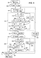
- Figure 1 is a block diagram of an embodiment of a video processing device.
- Figure 2 is a block diagram of an example of direction selection unit usable in the device of figure 1 .
- Figure 3 is a flow chart of an exemplary procedure of evaluating cost function margins in a device as illustrated in figures 1 and 2 .
- Figure 4 is a flow chart of an alternative embodiment of a loop used in the procedure of figure 3 .
- Figures 5 and 6 are flow charts of exemplary procedures of arbitrating between candidate directions in a device as illustrated in figures 1 and 2 .
- Figures 7 and 8 are diagrams illustrating frame rate conversion processing applied to certain image portions.
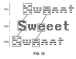
- Figures 9 , 10 , 11 and 12 are diagrams illustrating video deinterlacing processing applied to similar image portions.
- Figure 13 is a block diagram of a video processing apparatus according to an embodiment of the invention.
- a video processing device has an input receiving digital representations of successive images or frames of a video sequence.
- I t , I t+1 denote frames at discrete times t and t+1
- How the time indexes t and spatial indexes x are managed may differ from one video processing application to another, e.g. between deinterlacing, frame rate conversion and noise reduction. This issue will be addressed further below.
- a direction selection unit 101 implements a time recursive estimation to determine a subset D ⁇ , of candidate directions for an output frame Î ⁇ ' based on a previous subset D ⁇ and on the consecutive input frames.
- the aforesaid "previous subset D ⁇ " was determined for an output frame î ⁇ which immediately precedes Î ⁇ ' in the output video sequence.
- ⁇ ' ⁇ +1 for deinterlacing or simple noise reduction
- ⁇ ' ⁇ + ⁇ r for frame rate conversion or super-resolution noise reduction.
- the input frames involved in the determination of the subset D ⁇ ' at time ⁇ ' include at least I t and I t+1 such that t ⁇ ' ⁇ t+1. In certain embodiments, they may further include a few past frames I t-1 , ..., I t-n (n ⁇ 1).
- dx (dx 1 , dx 2 ) in the 2D image space
- dt (dx 1 , dx 2 ) in the 2D image space
- the third direction relates to a time offset dt.
- the value of an input pixel is corrupted by noise which can be averaged out if it is possible to identify some neighborhood of "similar" pixels. Again, such a neighborhood can extend in the 2D image space and/or in time.
- the method described below yields directions of regularity for pixels of the images which help determining the "similar" pixel values useful to the processing.
- the subset D ⁇ or D ⁇ ' is said to define a sparse geometry.
- Each subset D ⁇ or D ⁇ ' is a subset of a set ⁇ containing all the possible directions of regularity.
- the geometry defined by D ⁇ , D ⁇ is said to be sparse because for each instant ⁇ , ⁇ ', the number of different directions that can be used is limited to a relatively small number.
- the subset of candidate directions D ⁇ , D ⁇ ', ... evolves in time with marginal changes. Directions that would be redundant in D ⁇ , D ⁇ ' , are removed and not used for the pixel-by-pixel processing.
- ⁇ can contain 200 to 1000 different directions (200 ⁇
- the subsets D ⁇ , D ⁇ ' ... can have their sizes limited in the range 10 ⁇
- a direction detection unit 102 determines a distribution of directions of regularity ⁇ v ⁇ based on the consecutive frames I t , I t+1 (and possibly a few past frames I t-1 , ..., I t-n ) by testing only candidate directions belonging to the subset D ⁇ ' determined by the selection unit 101.
- the reduction in size from ⁇ to D ⁇ ' makes it possible to carry out the detection without requiring an exceedingly high complexity.
- the video processing unit 103 uses the detected directions of regularity ⁇ v ⁇ to perform a video processing, such as deinterlacing, frame rate conversion or noise reduction, to deliver output video frames from the input frames I t , I t+1 .
- a video processing such as deinterlacing, frame rate conversion or noise reduction
- Units 102 and 103 can implement any conventional or state-of-the-art methods, and simple examples will be given for completeness.
- the detection unit 102 can use the loss function described in WO 2007/115583 A1 .
- the core of the invention lies in unit 101 that will be described in greater detail.
- the direction selection unit 101 considers a much larger set of directions than the direction detection unit 102, an interesting possibility is to use a simpler or cost function in unit 101 than in unit 102.
- the local cost functions are estimated more coarsely in the step of determining the direction subset D ⁇ ' (selection unit 101) than in the step of picking the directions from that subset (direction detection unit 102). This provides substantial savings in terms of computational complexity or, equivalently, in terms of ASIC/FPGA logic size.
- the aim of the selection unit 101 is to compute a subset of directions D ⁇ ' providing a useful description of the local regularity of the video sequence at an instant ⁇ ' in the output sequence.
- the best subset D is the one that minimizes a global cost (or loss) function L(D):
- L D ⁇ x min v ⁇ D L x v where the sum over the pixels (x) spans the whole image area (or part of it).
- the direction selection unit 101 as depicted in figure 2 has a block 201 for evaluating margins m(v) for different directions v of the set of possible directions ⁇ , and an arbitration block 202 to decide, based on the margins m(v) which directions of D ⁇ should be excluded from D ⁇ ' and which directions of ⁇ -D ⁇ should be included into D ⁇ ' .
- the directions v selected to be added to D ⁇ to get D ⁇ ' are chosen depending on how much they would marginally contribute to improving (reducing) the cost function L(D) according to (1).
- the directions v to be removed from D ⁇ are chosen depending on how little they marginally contribute to reducing that cost function L(D).
- D) for a fixed D and for each x and each candidate v in ⁇ -D can be done by determining the quantifies L x (D) and L x (v). Then m(v
- the exchange margin M' exch (v a , v r ) in (7) is not more than the actual exchange margin M exch (v a , v r ) in (5). If the approximated exchange margin M' exch (v a , v r ) is non-negative, the actual exchange margin M exch (v a , v r ) is also non-negative. So a swap decided based on (7) cannot be a wrong one from the point of view of (5).
- Figure 3 is a flow chart illustrating a procedure usable by block 201 to evaluate the margins m(v a
- m(v) stands for m(v r
- D ⁇ ) if the direction v ( v a ) is in ⁇ -D and may be added to D.
- the margins m(v) are evaluated for all directions v in ⁇ by updating running sums that are set to zero at the initialization 301 of the procedure.
- the procedure scans the pixels x of the frame arrays
- This first loop is initialized in step 311 by taking a first direction v in D and setting a variable A to an arbitrarily large value (for example its maximum possible value). At the end of loop 310, variable A will contain the value of L x (D) defined in (2).
- step 312 the local cost L x (v) for pixel x and direction v is obtained and loaded into variable L.
- block 201 can either compute L x (v), for example according to one of the above-mentioned possibilities, or retrieve it from a memory if the costs L x (v) were computed beforehand.
- a test 313 is performed to evaluate whether L is smaller than A. If L ⁇ A, the direction index v is stored in a variable u and a variable B receives the value A in step 314. Then the value L is allocated to the variable A in step 315.
- step 318 the end-of-loop test 318 is performed to check if all the directions v of D have been scanned. If not, another direction v of D is selected in step 319 and the procedure returns to step 312 for another iteration of loop 310.
- the margin m(u) of the direction u of D ⁇ which minimizes the local cost at pixel x is updated by adding thereto the quantity B-A (step 321). As far as pixel x is concerned, removing u from D would degrade the cost by that quantity while the margins for the other directions of D would remain unaffected.
- the processing for pixel x is then continued by a second loop 330 over the possible directions v that are not in D, in order to update the running sums for the directions of ⁇ -D regarding pixel x.
- This second loop is initialized in step 331 by taking a first direction v in ⁇ -D.
- the local cost L x (v) for pixel x and direction v is computed or retrieved to be loaded into variable L.
- step 334 the end-of-loop test 335 is performed to check if all the directions v of ⁇ -D have been scanned. If not, another direction v of ⁇ -D is selected in step 336 and the procedure returns to step 332 for another iteration of loop 330.
- test 341 When loop 330 is over, it is determined in test 341 if all pixels x of the relevant frame array have been scanned. If not, another pixel x of the array is selected in step 342 and the procedure returns to step 311. The operation of block 201 regarding the current frame is over when test 341 shows that all the pixels have been processed.
- block 201 For each new input frame I t+1 , block 201 thus outputs the margins m(v) for all directions v of ⁇ , i.e. removal margins for the directions of D and addition margins for the directions of ⁇ -D.
- the subset D can have an arbitrary content, or it can be determined with a coarse method over the first few frames. A correct subset will quickly be built due to the time recursion of the selection procedure.
- a second approximation can be made to further reduce the complexity of block 201.
- D ⁇ ) is replaced by a modified margin m*(v a
- D) is a pixelwise sum: m * v
- D ⁇ x m * x v
- the modified exchange margin M* exch (v a , v r ) is not more than the actual exchange margin M exch (v a , v r ), because of (6) and because m* x (v a
- D) can be computed with less expensive computations or circuitry because, for each location x, at most one running sum corresponding to a single absolute best direction in ⁇ -D has to be updated, whereas with non-modified margins m x (v a
- the impact on logic size is significant. For idenfical reasons, the impact on the worst-case execution time in a software implementation is also important.
- variable A* will contain the minimum of L x (v) for all directions v in ⁇ , i.e. L x ( ⁇ ).
- the local cost L x (v) for pixel x and direction v ⁇ ⁇ -D is computed or retrieved to be loaded into variable L in step 432.
- a test 433 is then performed to evaluate whether L is smaller than A*. If L ⁇ A*, the above-mentioned variable u is updated to contain the direction index v, and the value L is allocated to the variable A* in step 434. If L ⁇ A* in test 433, or after step 434, the end-of-loop test 435 is performed to check if all the directions v of ⁇ -D have been scanned. If not, a further direction v of ⁇ -D is selected in step 436 and the procedure returns to step 432 for another iteration of loop 430.
- step 4431 the margin m(u) of the direction u of ⁇ which minimizes the local cost at pixel x is updated by adding thereto the quantity A-A* (step 441). If u ⁇ D, step 441 changes nothing. If u ⁇ D, adding u to D would reduce the cost function by A-A* as far as pixel x is concerned, while the margins for the other directions of ⁇ -D would remain unaffected.
- Figure 6 illustrates another approach in which block 202 can swap more than one pair of directions.
- the number n can be any integer between 1 and
- . In the case n 1, the procedure of figure 6 is the same as that of figure 5 .
- the inclusion of new directions w of ⁇ -D t into D ⁇ ' can be prevented when m(w) is below the threshold T.
- the number n can be set as the largest integer in ⁇ 1, 2, ...,
- the use of the threshold T helps to prune the set of candidate directions and to select a number of candidate directions that is adapted to the geometric complexity of the video, i.e. to select the sparsest set of directions suitable for the video.
- Figures 7 and 8 illustrate the results provided by an embodiment of the invention in a case where the video processing unit 103 performs interpolation and more particularly frame rate conversion with a ratio of 2 between the frame rates of the output and input video sequences.
- the video sequence in this example is a horizontally scrolling caption with the text "Sweeet".
- 701 and 801 denote the image at time t
- images 701/801 and 703/803 times t and t+1
- the whole text "Sweeet" has scrolled 10 pixels to the left.
- a possible cause for mismatch is that the text contains several times the letter "e” with a periodicity of 8 pixels, and the direction detection unit 102 might be mistaken by the first "e” at time t looking like another "e” in the next input image at time t+1, leading to artifacts as shown in 702.
- the direction v (2) will be kept out of the set D ⁇ ' so that it will not be taken into account in the detection unit 102, or will be ignored because its margin is below a threshold T.
- the correct interpolation will be computed as depicted in 802.
- the loss function used in units 101 and 102 can then be adapted accordingly.
- Figures 9-12 are diagrams similar to figures 7-8 illustrating application of an embodiment of the invention to super-resolution video deinterlacing.
- Figures 9-10 show the same text "Sweeet" scrolling in an interlaced video format at the input of the apparatus.
- References 901, 1001, 1101 and 1201 show an even input field at time t-1
- references 903, 1003, 1103 and 1203 show the next even input field at time t+1
- references 902 and 1002 show the intervening odd input field at time t.
- Another possibility in deinterlacing applications is to compute costs for directions where the fields are shot at irregularly spaced times, in addition to directions associated with fields shot at evenly spaced times. This is for example the case when the original source of the video contents is film converted to video using "telecine". For example, in 2:2 telecine used in Europe, when 25 fps (frames per second) film is transferred to 50 fps video, each film frame is used to generate two video fields, so fields I 0 , I 1 , I 2 , I 3 are shot at respective times 0s, 0s, 2/50s, 2/50s, instead of times 0/50s, 1/50s, 2/50s, 3/50s for video-originating contents.
- a video signal can contain a mix of film-originating contents and video-originating contents, so this detection has to be made pixelwise.
- Specific local cost functions can be chosen for detecting whether for a given pixel, the video is film-originating and whether the field just before or just after originates from the same film frame.
- a configuration of the direction at each pixel is then one of the following:
- the video processing performed in the processing unit 103 receives a variable number of directions from the direction detection unit 102.
- Each of these directions can be accompanied with a relevance measure.
- a fallback interpolation function or averaging function can be used.
- the target pixel value can be computed by combining the pixel values computed with each interpolating or averaging function corresponding to each direction. This combination can be an averaging, a weighted averaging using the relevance measure, or a median, or a weighted median, or any other kind of method to combine these pixel values.
- IIR infinite impulse response
- the sparse geometry is used to enhance the type of processing disclosed in WO 2007/059795 A1 when the processed signal is a video signal.
- the set ⁇ 2 of candidate directions is partitioned into a plurality of subsets ⁇ 1 , ..., ⁇ J (J > 1), and only one of the subsets ⁇ 1 , ..., ⁇ J is considered by the direction selection unit 101 at each time ⁇ ' to provide candidates to enter the subset of selected directions D ⁇ ' .
- This is interesting when the set ⁇ is too large to be entirely scanned for candidates in every cycle ⁇ '. For example, at a time when subset ⁇ j is considered (1 ⁇ j ⁇ J), loop 330 in figure 3 or 430 in figure 4 is carried out for the directions v that are in ⁇ j but not in D.
- W p ,q x 1 x 2 : w ⁇ p - 1 ⁇ x 1 ⁇ w ⁇ p and h ⁇ q - 1 ⁇ x 2 ⁇ h ⁇ q
- h and w are respectively the height and the width (in pixels) of these windows
- the window indexes p, q are in the ranges 1 ⁇ p ⁇ P, 1 ⁇ q ⁇ Q.
- the total number of windows is P ⁇ Q.
- D) can be computed using a formula similar to (4), but with a sum spanning an image region limited to this window W p,q : m p , q v
- D ⁇ x ⁇ W p , q m x v
- a third subset D ⁇ ',p,q of candidate directions is thus determined as a subset of the second subset D ⁇ ' determined for the whole area of I t+1 , based on cost margins m p,q (v
- the selection allows to eliminate a bad direction (-1,0, 1/2) [or (-2, 0,1)] and to only use the right direction (-5, 0, 1/2) [or (-10, 0,1)]. If the scene is more complex and somewhere else in the picture an object happens to be exhibiting a direction of regularity (-1,0, 1/2), this vector (-1,0, 1/2) will be present in D ⁇ ' , and the benefit of the selection made in unit 101 may be lost to properly handle the scrolling text. If the selection margins are recomputed on smaller windows W p,q , the probability that such a window W p,q includes both the scrolling text and the object having the single direction of regularity (-1,0, 1/2) will be much lower.
- a multiscale selection scheme can be devised to avoid this difficulty, by recursively splitting the image support into windows, and each window into sub-windows. For each window, the subset of directions is selected as a subset of the subset of directions that was selected for the parent region (whole image or higher-layer window).
- one or more of the windows W p,q is further split into a plurality of sub-windows W p,q,r,s , and for each sub-window a fourth subset D ⁇ ',p,q,r,s of candidate directions is determined as a subset of the third subset D ⁇ ',p,q determined for the window W p,q , based on cost margins m p,q,r,s (v
- D ⁇ x ⁇ W p , q , r , s m x v
- the directions of regularity for pixels of sub-window W p,q,r,s of the output image Î ⁇ ' are then detected from subset D ⁇ ',p,q,r , s
- the subset D ⁇ ' of selected directions can be constrained to satisfy various criteria. For example:
- the above-described embodiments may be implemented by means of software run by general-purpose microprocessors or digital signal processors, in which case the modules described above with reference to figures 1-6 are understood to be or form part of software modules or routines. It may also be implemented as a hardware component as illustrated in figure 13 , for example in an application-specific integrated circuit (ASIC) or field-programmable gate array (FPGA) for interpolating a video stream, in addition to other video processing blocks 1302, 1304, before and/or after the video interpolation block 1303. Alternatively, the video processing block 1303 may implement a noise reduction method as described above. In an exemplary embodiment, the video processing blocks 1302, 1303, 1304 are implemented in a single chip 1301.
- ASIC application-specific integrated circuit
- FPGA field-programmable gate array
- the chip also has video input and output interfaces, and external RAM (random access memory) devices 1305 and 1306 as temporary storage required for the different video processing steps performed in 1302, 1303 and 1304.
- RAM random access memory
- Other variants of this embodiment can be equally considered as part of the invention, with more complete video processing chips, or even system-on-chip devices including other functionalities.
- the hardware device can then be incorporated into various kinds of video apparatus.
Landscapes
- Engineering & Computer Science (AREA)
- Multimedia (AREA)
- Signal Processing (AREA)
- Computer Vision & Pattern Recognition (AREA)
- Physics & Mathematics (AREA)
- General Physics & Mathematics (AREA)
- Theoretical Computer Science (AREA)
- Television Systems (AREA)
- Image Processing (AREA)
Claims (16)
- Verfahren zum Analysieren einer Eingangsvideosequenz, um Pixel von synthetisierten Bildern einer Ausgangsvideosequenz jeweiligen Regularitätsrichtungen, die einer vordefinierten Menge von Richtungen (Ω) angehören, zuzuordnen, wobei das Verfahren umfasst:- Bestimmen, aus der vordefinierten Menge von Richtungen, einer ersten Teilmenge (Dτ) von Kandidatenrichtungen für einen Bereich eines ersten Bildes (Îτ) der Ausgangssequenz,- Bestimmen (101), aus der vordefinierten Menge von Richtungen, einer zweiten Teilmenge (Dτ') von Kandidatenrichtungen für einen entsprechenden Bereich eines zweiten synthetisierten Bildes (Îτ,) der Ausgangssequenz, welches dem ersten Bild folgt, basierend auf Bildern (It, It+1) der Eingangssequenz und der ersten Teilmenge von Kandidatenrichtungen (Dτ) und- Detektieren (102) der Regularitätsrichtungen für Pixel von dem Bereich des zweiten synthetisierten Bildes aus der zweiten Teilmenge von Kandidatenrichtungen,
dadurch gekennzeichnet, dass die Bestimmung der zweiten Teilmenge (Dτ') von Kandidatenrichtungen umfasst:- Bewerten von ersten Rändern, die sich auf jeweilige Beiträge von individuellen Richtungen der ersten Teilmenge (Dτ) auf eine der ersten Teilmenge zugeordnete Kostenfunktion beziehen,- Bewerten von zweiten Rändern, die sich auf jeweilige Dekremente der Kostenfunktion beziehen, welche aus der Addition von individuellen Richtungen der vordefinierten Menge (Ω) zu der ersten Teilmenge resultieren, und- Ersetzen einer Richtung der vordefinierten Menge durch eine Richtung der ersten Untermenge, wenn der zweite Rand, der für die Richtung der vordefinierten Menge bewertet worden ist, den ersten Rand, der für die Richtung der ersten Untermenge bewertet worden ist, übersteigt. - Verfahren nach Anspruch 1, wobei der erste Rand für eine Richtung der ersten Teilmenge (Dτ) gleich dem Beitrag der Richtung zu der Kostenfunktion ist.
- Verfahren nach Anspruch 1 oder 2, wobei der zweite Rand für eine Richtung der vordefinierten Menge (Ω) gleich dem Dekrement der Kostenfunktion, welches aus der Addition der Richtung mit der ersten Teilmenge (Dτ) resultiert, ist oder als eine Summe von lokalen Rändern über die Pixel des Bereichs geschätzt wird, wobei ein lokaler Rand für ein Pixel x und eine Richtung v ist:Lx(D) - Lx(v), wenn v die beste Richtung in der gesamten vordefinierten Menge (Ω) hinsichtlich einer Minimierung von lokalen Kosten bei der Pixel-Position x ist, wobei Lx(v) die lokalen Kosten bei der Pixel-Position x für die Richtung v bezeichnet und Lx(D) einen Minimalwert der lokalen Kosten bei der Pixel-Position x für die Richtungen der ersten Teilmenge (Dτ) bezeichnet, undansonsten Null.
- Verfahren nach einem der Ansprüche 1 bis 3, umfassend:- Auswählen (501) einer ersten Richtung (v), die den niedrigsten ersten Rand in der ersten Teilmenge (Dτ) aufweist,- Auswählen (502) einer zweiten Richtung (w), die den höchsten zweiten Rand in der vordefinierten Menge (Ω), außer der ersten Teilmenge (Dτ), aufweist, und- wenn der zweite Rand für die ausgewählte zweite Richtung über dem ersten Rand für die ausgewählte erste Richtung liegt, Ausschließen der ausgewählten ersten Richtung aus der zweiten Teilmenge (Dτ') und Einschließen der gewählten zweiten Richtung in die zweite Teilmenge (Dτ').
- Verfahren nach einem der Ansprüche 1 bis 3, umfassend:- Auswählen und Sortieren nach zunehmenden Rändern (601) einer Anzahl n von Richtungen v1, v2, ..., vn, die die niedrigsten ersten Ränder in der ersten Teilmenge (Dτ) aufweisen,- Auswählen und Sortieren nach abnehmenden Rändern (602) der n Richtungen w1, w2, ..., wn, die die höchsten zweiten Ränder in der vordefinierten Menge (Ω), außer der ersten Teilmenge (Dτ), aufweisen, und- für jede Richtung wi von den n sortierten Richtungen w1, w2, ..., wn von der vordefinierten Menge, außer der ersten Teilmenge, mit 1 ≤ i ≤ n, wenn der zweite Rand über dem ersten Rand für die entsprechende Richtung vi von den n sortierten Richtungen v1, v2, ..., vn von der vordefinierten Menge, außer der ersten Teilmenge, liegt, Ausschließen von vi von der zweiten Teilmenge (Dτ') und Einschließen von wi in die zweite Teilmenge (Dτ').
- Verfahren nach einem der Ansprüche 1 bis 5, ferner umfassend Ausschließen von Richtungen der vordefinierten Menge (Ω), die einen bewerteten Rand unter einem voreingestellten Schwellenwert aufweisen, aus der zweiten Teilmenge (Ωτ').
- Verfahren nach einem der Ansprüche 1 bis 6, wobei die Kostenfunktion, die einer vorgegebenen Teilmenge (D) von Richtungen zugeordnet ist, eine Summe, über die Pixel der Bereiche, von Minimalwerten von lokalen Kosten für die verschiedenen Richtungen der gegebenen Teilmenge ist.
- Verfahren nach einem der vorhergehenden Ansprüche, wobei die Schritte des Bestimmens der zweiten Teilmenge (Dτ') von Kandidatenrichtungen und des Detektierens der Richtungen von der zweiten Teilmenge ein Schätzen umfasst von Funktionen lokaler Kosten zwischen den wenigstens zwei aufeinanderfolgenden Bildern (It, It+1) der Eingangssequenz mit jeweiligen Zeitpositionen vor und nach dem zweiten synthetisierten Bild (Îτ') der Ausgangssequenz, und wobei die Funktionen lokaler Kosten gröber in dem Schritt des Bestimmens der zweiten Teilmenge als in dem Schritt des Detektierens der Regularitätsrichtungen von der zweiten Teilmenge geschätzt werden.
- Verfahren nach einem der vorhergehenden Ansprüche, wobei wenigstens eine voreingestellte Richtung zwangweise in die erste und die zweite Teilmenge (Dτ, Dτ') eingefügt wird.
- Verfahren nach einem der vorhergehenden Ansprüche, wobei die vordefinierte Menge von Richtungen (Ω) in eine Mehrzahl von Clustern (Ω(r)) unterteilt wird, und bei der Bestimmung der zweiten Teilmenge (Dτ') von Kandidatenrichtungen eine oder eine begrenzte Anzahl von Richtungen von jedem Cluster ausgewählt wird, um in die zweite Teilmenge eingefügt zu werden.
- Verfahren nach einem der vorhergehenden Ansprüche, wobei die Bilder der Videosequenzen in eine Mehrzahl von Fenstern (Wp,q) aufgespaltet werden, wobei die zweite Teilmenge von Kandidatenrichtungen (Dτ') für einen Bereich bestimmt wird, der der gesamten Fläche des zweiten synthetisierten Bildes entspricht, wobei das Verfahren ferner für jedes Fenster umfasst:- Bestimmen einer dritten Teilmenge (Dτ',p,q) von Kandidatenrichtungen als eine Teilmenge der zweiten Teilmenge, basierend auf Kostenrändern, die für Pixel des Fensters bestimmt worden sind, und- Detektieren der Regularitätsrichtungen für Pixel des Fensters des zweiten synthetisierten Bildes von der dritten Teilmenge von Kandidatenrichtungen.
- Verfahren nach Anspruch 11, wobei wenigstens eines der Fenster (Wp,q) weiter in eine Mehrzahl von Unterfenstern (Wp,q,r,s) aufgespaltet wird, wobei das Verfahren ferner für jedes Unterfenster des Fensters umfasst:- Bestimmen einer vierten Teilmenge (Dτ',p,q.r.s) von Kandidatenrichtungen als eine Teilmenge der dritten Teilmenge (Dτ',p,q), die für das Fenster bestimmt ist, basierend auf Kostenrändern, die für Pixel des Unterfensters bestimmt sind, und- Detektieren der Regularitätsrichtungen für Pixel des Unterfensters des zweiten synthetisierten Bildes von der vierten Untermenge von Kandidatenrichtungen.
- Videoverarbeitungsvorrichtung, umfassend Berechnungsschaltkreise, die eingerichtet sind, eine Videosequenz gemäß einem Verfahren nach einem der Ansprüche 1 bis 11 zu analysieren.
- Computerprogrammprodukt, umfassend Anweisungen, um ein Verfahren zum Analysieren einer Videosequenz nach einem der Ansprüche 1 bis 10 auszuführen, wenn das Programmprodukt in einer Computerverarbeitungseinheit zum Laufen gebracht wird.
- Videoverarbeitungsverfahren, umfassend:- Empfangen von aufeinanderfolgenden Bildern (It, It+1) einer Eingangsvideosequenz,- Analysieren der Eingangsvideosequenz unter Anwendung eines Verfahrens nach einem der Ansprüche 1 bis 12, um Pixel von synthetisierten Bildern einer Ausgangsvideosequenz jeweiligen Regularitätsrichtungen zuzuordnen, und- Erzeugen der Ausgangsvideosequenz aus der Eingangsvideosequenz unter Verwendung der detektierten Regularitätsrichtungen,wobei das Erzeugen der Ausgangsvideosequenz umfasst: Durchführen einer Interpolation zwischen aufeinanderfolgenden Bildern der Eingangsvideosequenz unter Verwendung der detektierten Regularitätsrichtungen, wobei die Interpolation eine Video-Zeilenentflechtung oder Bildratenkonvertierung umfasst; oder Anwenden einer Rauschreduktionsoperation auf die Eingangsvideosequenz unter Verwendung der detektierten Regularitätsrichtungen.
- Videoverarbeitungsvorrichtung, umfassend Berechnungsschaltkreise, die eingerichtet sind, eine Videosequenz mit einem Verfahren nach Anspruch 15 zu verarbeiten.
Applications Claiming Priority (1)
| Application Number | Priority Date | Filing Date | Title |
|---|---|---|---|
| PCT/IB2008/051270 WO2009087493A1 (en) | 2008-01-11 | 2008-01-11 | Sparse geometry for super resolution video processing |
Publications (2)
| Publication Number | Publication Date |
|---|---|
| EP2240905A1 EP2240905A1 (de) | 2010-10-20 |
| EP2240905B1 true EP2240905B1 (de) | 2012-08-08 |
Family
ID=39745405
Family Applications (1)
| Application Number | Title | Priority Date | Filing Date |
|---|---|---|---|
| EP08719873A Not-in-force EP2240905B1 (de) | 2008-01-11 | 2008-01-11 | Verstreute geometrie für hochauflösende videoverarbeitung |
Country Status (6)
| Country | Link |
|---|---|
| US (2) | US8571114B2 (de) |
| EP (1) | EP2240905B1 (de) |
| JP (1) | JP2011509617A (de) |
| KR (1) | KR20100118978A (de) |
| CN (1) | CN101971209A (de) |
| WO (1) | WO2009087493A1 (de) |
Families Citing this family (13)
| Publication number | Priority date | Publication date | Assignee | Title |
|---|---|---|---|---|
| US8351510B1 (en) | 2008-02-01 | 2013-01-08 | Zenverge, Inc. | Motion compensated noise reduction using shared motion estimation engine |
| WO2010091934A1 (en) | 2009-02-12 | 2010-08-19 | Zoran (France) | Video sequence analysis for robust motion estimation |
| WO2010091937A1 (en) | 2009-02-12 | 2010-08-19 | Zoran (France) | Temporal video interpolation method with 2-frame occlusion handling |
| ATE547775T1 (de) | 2009-08-21 | 2012-03-15 | Ericsson Telefon Ab L M | Verfahren und vorrichtung zur schätzung von interframe-bewegungsfeldern |
| US8928806B2 (en) | 2010-03-15 | 2015-01-06 | Zoran (France) S.A. | Video interpolation method and apparatus with smooth fallback interpolation mode |
| WO2011120600A1 (en) | 2010-04-02 | 2011-10-06 | Zoran (France) | Cadence detection for interlaced video based on temporal regularity |
| CN102063729A (zh) * | 2010-12-30 | 2011-05-18 | 哈尔滨工业大学 | 基于二维稀疏性的压缩感知图像重建方法 |
| CN102685370B (zh) * | 2012-05-10 | 2013-04-17 | 中国科学技术大学 | 一种视频序列的去噪方法及装置 |
| US9691133B1 (en) | 2013-12-16 | 2017-06-27 | Pixelworks, Inc. | Noise reduction with multi-frame super resolution |
| TWI493476B (zh) * | 2014-01-02 | 2015-07-21 | Mstar Semiconductor Inc | 影像處理電路與方法 |
| CN113239236B (zh) * | 2021-07-13 | 2021-10-01 | 北京达佳互联信息技术有限公司 | 视频处理方法、装置、电子设备及存储介质 |
| CN115147769B (zh) * | 2022-07-29 | 2026-01-09 | 中南大学 | 一种基于红外视频的生理参数鲁棒性检测方法 |
| JP2024035950A (ja) * | 2022-09-05 | 2024-03-15 | シャープ株式会社 | コンテンツ管理装置、コンテンツ管理方法、及び、コンピュータプログラム |
Family Cites Families (17)
| Publication number | Priority date | Publication date | Assignee | Title |
|---|---|---|---|---|
| EP0261137B1 (de) | 1986-03-19 | 1991-10-16 | British Broadcasting Corporation | Fernsehbild-bewegungsmessung |
| US5428398A (en) | 1992-04-10 | 1995-06-27 | Faroudja; Yves C. | Method and apparatus for producing from a standard-bandwidth television signal a signal which when reproduced provides a high-definition-like video image relatively free of artifacts |
| TW321748B (de) | 1994-02-23 | 1997-12-01 | Rca Thomson Licensing Corp | |
| EP0840982B1 (de) * | 1996-05-24 | 2002-02-13 | Koninklijke Philips Electronics N.V. | Bewegungsschätzung |
| JPH10262254A (ja) * | 1997-03-18 | 1998-09-29 | Matsushita Electric Ind Co Ltd | 動きベクトル検出方法およびその装置 |
| EP0972407A2 (de) * | 1998-02-06 | 2000-01-19 | Koninklijke Philips Electronics N.V. | Schätzung von bewegung und tiefe |
| US6845130B1 (en) * | 2000-10-12 | 2005-01-18 | Lucent Technologies Inc. | Motion estimation and compensation for video compression |
| US6940557B2 (en) | 2001-02-08 | 2005-09-06 | Micronas Semiconductors, Inc. | Adaptive interlace-to-progressive scan conversion algorithm |
| KR100446235B1 (ko) * | 2001-05-07 | 2004-08-30 | 엘지전자 주식회사 | 다중 후보를 이용한 움직임 벡터 병합 탐색 방법 |
| US6925123B2 (en) * | 2002-08-06 | 2005-08-02 | Motorola, Inc. | Method and apparatus for performing high quality fast predictive motion search |
| WO2004064403A1 (en) * | 2003-01-10 | 2004-07-29 | Koninklijke Philips Electronics N.V. | Efficient predictive image parameter estimation |
| DE10327577A1 (de) * | 2003-06-18 | 2005-01-13 | Micronas Gmbh | Verfahren zur Ermittlung eines Verschiebungsvektors in der Bildverarbeitung |
| US20060133495A1 (en) * | 2004-12-22 | 2006-06-22 | Yan Ye | Temporal error concealment for video communications |
| EP1952343A1 (de) | 2005-11-25 | 2008-08-06 | Let it Wave | Verfahren und vorrichtung zum verbessern von signalen mit gruppierungs-bandlets auf mehreren massstäben |
| WO2007115583A1 (en) | 2006-04-12 | 2007-10-18 | Zoran (France) | Method and apparatus for robust super-resolution video scaling |
| JP2008011197A (ja) * | 2006-06-29 | 2008-01-17 | Toshiba Corp | 動きベクトル検出装置、動きベクトル検出方法および補間フレーム作成装置 |
| DE102006043707A1 (de) * | 2006-09-18 | 2008-03-27 | Robert Bosch Gmbh | Verfahren zur Datenkompression in einer Videosequenz |
-
2008
- 2008-01-11 WO PCT/IB2008/051270 patent/WO2009087493A1/en not_active Ceased
- 2008-01-11 CN CN2008801280248A patent/CN101971209A/zh active Pending
- 2008-01-11 KR KR1020107017363A patent/KR20100118978A/ko not_active Withdrawn
- 2008-01-11 US US12/812,201 patent/US8571114B2/en not_active Expired - Fee Related
- 2008-01-11 JP JP2010541855A patent/JP2011509617A/ja not_active Ceased
- 2008-01-11 EP EP08719873A patent/EP2240905B1/de not_active Not-in-force
-
2013
- 2013-09-27 US US14/040,035 patent/US20140023149A1/en not_active Abandoned
Also Published As
| Publication number | Publication date |
|---|---|
| KR20100118978A (ko) | 2010-11-08 |
| US8571114B2 (en) | 2013-10-29 |
| JP2011509617A (ja) | 2011-03-24 |
| US20110058106A1 (en) | 2011-03-10 |
| EP2240905A1 (de) | 2010-10-20 |
| US20140023149A1 (en) | 2014-01-23 |
| CN101971209A (zh) | 2011-02-09 |
| WO2009087493A1 (en) | 2009-07-16 |
Similar Documents
| Publication | Publication Date | Title |
|---|---|---|
| EP2240905B1 (de) | Verstreute geometrie für hochauflösende videoverarbeitung | |
| CN101422047B (zh) | 图像边界处的运动估计方法及显示设备 | |
| Kang et al. | Motion compensated frame rate up-conversion using extended bilateral motion estimation | |
| JP5657391B2 (ja) | ハローを低減する画像補間 | |
| US8265158B2 (en) | Motion estimation with an adaptive search range | |
| US7570309B2 (en) | Methods for adaptive noise reduction based on global motion estimation | |
| US20030086498A1 (en) | Apparatus and method of converting frame and/or field rate using adaptive motion compensation | |
| CN100499738C (zh) | 考虑水平和垂直图形的全局运动补偿的顺序扫描方法 | |
| US20040125231A1 (en) | Method and apparatus for de-interlacing video signal | |
| US20110188583A1 (en) | Picture signal conversion system | |
| US7944503B1 (en) | Interlaced-to-progressive video processing | |
| US6614485B2 (en) | Deinterlacing apparatus | |
| US8675128B2 (en) | Image processing method and system with repetitive pattern detection | |
| Kaviani et al. | Frame rate upconversion using optical flow and patch-based reconstruction | |
| US20050180506A1 (en) | Unit for and method of estimating a current motion vector | |
| CN101496063A (zh) | 用于创建内插图像的方法和系统 | |
| US7403234B2 (en) | Method for detecting bisection pattern in deinterlacing | |
| EP1514241A2 (de) | Vorrichtung und verfahren zur vorhersage eines bewegungsvektors | |
| JP2008148315A (ja) | 画像復元方法および画像復元装置 | |
| EP1623568A1 (de) | Aufhebung des zeilensprungverfahrens von videodaten | |
| AU2004200237B2 (en) | Image processing apparatus with frame-rate conversion and method thereof | |
| US7881500B2 (en) | Motion estimation with video mode detection | |
| JP5448983B2 (ja) | 解像度変換装置及び方法、走査線補間装置及び方法、並びに映像表示装置及び方法 | |
| US8698954B2 (en) | Image processing method, image processing apparatus and image processing program | |
| Roussel et al. | Improvement of conventional deinterlacing methods with extrema detection and interpolation |
Legal Events
| Date | Code | Title | Description |
|---|---|---|---|
| PUAI | Public reference made under article 153(3) epc to a published international application that has entered the european phase |
Free format text: ORIGINAL CODE: 0009012 |
|
| 17P | Request for examination filed |
Effective date: 20100805 |
|
| AK | Designated contracting states |
Kind code of ref document: A1 Designated state(s): AT BE BG CH CY CZ DE DK EE ES FI FR GB GR HR HU IE IS IT LI LT LU LV MC MT NL NO PL PT RO SE SI SK TR |
|
| AX | Request for extension of the european patent |
Extension state: AL BA MK RS |
|
| DAX | Request for extension of the european patent (deleted) | ||
| 17Q | First examination report despatched |
Effective date: 20110712 |
|
| RIC1 | Information provided on ipc code assigned before grant |
Ipc: H04N 7/26 20060101ALI20120229BHEP Ipc: H04N 5/14 20060101ALI20120229BHEP Ipc: G06T 7/20 20060101AFI20120229BHEP |
|
| GRAP | Despatch of communication of intention to grant a patent |
Free format text: ORIGINAL CODE: EPIDOSNIGR1 |
|
| GRAS | Grant fee paid |
Free format text: ORIGINAL CODE: EPIDOSNIGR3 |
|
| GRAA | (expected) grant |
Free format text: ORIGINAL CODE: 0009210 |
|
| AK | Designated contracting states |
Kind code of ref document: B1 Designated state(s): AT BE BG CH CY CZ DE DK EE ES FI FR GB GR HR HU IE IS IT LI LT LU LV MC MT NL NO PL PT RO SE SI SK TR |
|
| REG | Reference to a national code |
Ref country code: GB Ref legal event code: FG4D |
|
| REG | Reference to a national code |
Ref country code: CH Ref legal event code: EP Ref country code: AT Ref legal event code: REF Ref document number: 570110 Country of ref document: AT Kind code of ref document: T Effective date: 20120815 |
|
| REG | Reference to a national code |
Ref country code: IE Ref legal event code: FG4D |
|
| REG | Reference to a national code |
Ref country code: DE Ref legal event code: R096 Ref document number: 602008017794 Country of ref document: DE Effective date: 20121004 |
|
| REG | Reference to a national code |
Ref country code: NL Ref legal event code: VDEP Effective date: 20120808 |
|
| REG | Reference to a national code |
Ref country code: AT Ref legal event code: MK05 Ref document number: 570110 Country of ref document: AT Kind code of ref document: T Effective date: 20120808 |
|
| REG | Reference to a national code |
Ref country code: LT Ref legal event code: MG4D Effective date: 20120808 |
|
| PG25 | Lapsed in a contracting state [announced via postgrant information from national office to epo] |
Ref country code: LT Free format text: LAPSE BECAUSE OF FAILURE TO SUBMIT A TRANSLATION OF THE DESCRIPTION OR TO PAY THE FEE WITHIN THE PRESCRIBED TIME-LIMIT Effective date: 20120808 Ref country code: AT Free format text: LAPSE BECAUSE OF FAILURE TO SUBMIT A TRANSLATION OF THE DESCRIPTION OR TO PAY THE FEE WITHIN THE PRESCRIBED TIME-LIMIT Effective date: 20120808 Ref country code: HR Free format text: LAPSE BECAUSE OF FAILURE TO SUBMIT A TRANSLATION OF THE DESCRIPTION OR TO PAY THE FEE WITHIN THE PRESCRIBED TIME-LIMIT Effective date: 20120808 Ref country code: IS Free format text: LAPSE BECAUSE OF FAILURE TO SUBMIT A TRANSLATION OF THE DESCRIPTION OR TO PAY THE FEE WITHIN THE PRESCRIBED TIME-LIMIT Effective date: 20121208 Ref country code: FI Free format text: LAPSE BECAUSE OF FAILURE TO SUBMIT A TRANSLATION OF THE DESCRIPTION OR TO PAY THE FEE WITHIN THE PRESCRIBED TIME-LIMIT Effective date: 20120808 Ref country code: NO Free format text: LAPSE BECAUSE OF FAILURE TO SUBMIT A TRANSLATION OF THE DESCRIPTION OR TO PAY THE FEE WITHIN THE PRESCRIBED TIME-LIMIT Effective date: 20121108 Ref country code: CY Free format text: LAPSE BECAUSE OF FAILURE TO SUBMIT A TRANSLATION OF THE DESCRIPTION OR TO PAY THE FEE WITHIN THE PRESCRIBED TIME-LIMIT Effective date: 20120808 |
|
| PG25 | Lapsed in a contracting state [announced via postgrant information from national office to epo] |
Ref country code: BE Free format text: LAPSE BECAUSE OF FAILURE TO SUBMIT A TRANSLATION OF THE DESCRIPTION OR TO PAY THE FEE WITHIN THE PRESCRIBED TIME-LIMIT Effective date: 20120808 Ref country code: GR Free format text: LAPSE BECAUSE OF FAILURE TO SUBMIT A TRANSLATION OF THE DESCRIPTION OR TO PAY THE FEE WITHIN THE PRESCRIBED TIME-LIMIT Effective date: 20121109 Ref country code: PL Free format text: LAPSE BECAUSE OF FAILURE TO SUBMIT A TRANSLATION OF THE DESCRIPTION OR TO PAY THE FEE WITHIN THE PRESCRIBED TIME-LIMIT Effective date: 20120808 Ref country code: LV Free format text: LAPSE BECAUSE OF FAILURE TO SUBMIT A TRANSLATION OF THE DESCRIPTION OR TO PAY THE FEE WITHIN THE PRESCRIBED TIME-LIMIT Effective date: 20120808 Ref country code: SE Free format text: LAPSE BECAUSE OF FAILURE TO SUBMIT A TRANSLATION OF THE DESCRIPTION OR TO PAY THE FEE WITHIN THE PRESCRIBED TIME-LIMIT Effective date: 20120808 Ref country code: SI Free format text: LAPSE BECAUSE OF FAILURE TO SUBMIT A TRANSLATION OF THE DESCRIPTION OR TO PAY THE FEE WITHIN THE PRESCRIBED TIME-LIMIT Effective date: 20120808 Ref country code: PT Free format text: LAPSE BECAUSE OF FAILURE TO SUBMIT A TRANSLATION OF THE DESCRIPTION OR TO PAY THE FEE WITHIN THE PRESCRIBED TIME-LIMIT Effective date: 20121210 |
|
| PG25 | Lapsed in a contracting state [announced via postgrant information from national office to epo] |
Ref country code: NL Free format text: LAPSE BECAUSE OF FAILURE TO SUBMIT A TRANSLATION OF THE DESCRIPTION OR TO PAY THE FEE WITHIN THE PRESCRIBED TIME-LIMIT Effective date: 20120808 |
|
| PG25 | Lapsed in a contracting state [announced via postgrant information from national office to epo] |
Ref country code: RO Free format text: LAPSE BECAUSE OF FAILURE TO SUBMIT A TRANSLATION OF THE DESCRIPTION OR TO PAY THE FEE WITHIN THE PRESCRIBED TIME-LIMIT Effective date: 20120808 Ref country code: DK Free format text: LAPSE BECAUSE OF FAILURE TO SUBMIT A TRANSLATION OF THE DESCRIPTION OR TO PAY THE FEE WITHIN THE PRESCRIBED TIME-LIMIT Effective date: 20120808 Ref country code: CZ Free format text: LAPSE BECAUSE OF FAILURE TO SUBMIT A TRANSLATION OF THE DESCRIPTION OR TO PAY THE FEE WITHIN THE PRESCRIBED TIME-LIMIT Effective date: 20120808 Ref country code: EE Free format text: LAPSE BECAUSE OF FAILURE TO SUBMIT A TRANSLATION OF THE DESCRIPTION OR TO PAY THE FEE WITHIN THE PRESCRIBED TIME-LIMIT Effective date: 20120808 Ref country code: ES Free format text: LAPSE BECAUSE OF FAILURE TO SUBMIT A TRANSLATION OF THE DESCRIPTION OR TO PAY THE FEE WITHIN THE PRESCRIBED TIME-LIMIT Effective date: 20121119 |
|
| PG25 | Lapsed in a contracting state [announced via postgrant information from national office to epo] |
Ref country code: IT Free format text: LAPSE BECAUSE OF FAILURE TO SUBMIT A TRANSLATION OF THE DESCRIPTION OR TO PAY THE FEE WITHIN THE PRESCRIBED TIME-LIMIT Effective date: 20120808 Ref country code: SK Free format text: LAPSE BECAUSE OF FAILURE TO SUBMIT A TRANSLATION OF THE DESCRIPTION OR TO PAY THE FEE WITHIN THE PRESCRIBED TIME-LIMIT Effective date: 20120808 |
|
| PLBE | No opposition filed within time limit |
Free format text: ORIGINAL CODE: 0009261 |
|
| STAA | Information on the status of an ep patent application or granted ep patent |
Free format text: STATUS: NO OPPOSITION FILED WITHIN TIME LIMIT |
|
| 26N | No opposition filed |
Effective date: 20130510 |
|
| PG25 | Lapsed in a contracting state [announced via postgrant information from national office to epo] |
Ref country code: BG Free format text: LAPSE BECAUSE OF FAILURE TO SUBMIT A TRANSLATION OF THE DESCRIPTION OR TO PAY THE FEE WITHIN THE PRESCRIBED TIME-LIMIT Effective date: 20121108 |
|
| PG25 | Lapsed in a contracting state [announced via postgrant information from national office to epo] |
Ref country code: MC Free format text: LAPSE BECAUSE OF NON-PAYMENT OF DUE FEES Effective date: 20130131 |
|
| REG | Reference to a national code |
Ref country code: CH Ref legal event code: PL |
|
| REG | Reference to a national code |
Ref country code: DE Ref legal event code: R097 Ref document number: 602008017794 Country of ref document: DE Effective date: 20130510 |
|
| REG | Reference to a national code |
Ref country code: IE Ref legal event code: MM4A |
|
| REG | Reference to a national code |
Ref country code: FR Ref legal event code: ST Effective date: 20130930 |
|
| PG25 | Lapsed in a contracting state [announced via postgrant information from national office to epo] |
Ref country code: CH Free format text: LAPSE BECAUSE OF NON-PAYMENT OF DUE FEES Effective date: 20130131 Ref country code: LI Free format text: LAPSE BECAUSE OF NON-PAYMENT OF DUE FEES Effective date: 20130131 |
|
| PG25 | Lapsed in a contracting state [announced via postgrant information from national office to epo] |
Ref country code: FR Free format text: LAPSE BECAUSE OF NON-PAYMENT OF DUE FEES Effective date: 20130131 |
|
| PG25 | Lapsed in a contracting state [announced via postgrant information from national office to epo] |
Ref country code: IE Free format text: LAPSE BECAUSE OF NON-PAYMENT OF DUE FEES Effective date: 20130111 |
|
| PG25 | Lapsed in a contracting state [announced via postgrant information from national office to epo] |
Ref country code: MT Free format text: LAPSE BECAUSE OF FAILURE TO SUBMIT A TRANSLATION OF THE DESCRIPTION OR TO PAY THE FEE WITHIN THE PRESCRIBED TIME-LIMIT Effective date: 20120808 |
|
| PG25 | Lapsed in a contracting state [announced via postgrant information from national office to epo] |
Ref country code: TR Free format text: LAPSE BECAUSE OF FAILURE TO SUBMIT A TRANSLATION OF THE DESCRIPTION OR TO PAY THE FEE WITHIN THE PRESCRIBED TIME-LIMIT Effective date: 20120808 |
|
| PG25 | Lapsed in a contracting state [announced via postgrant information from national office to epo] |
Ref country code: LU Free format text: LAPSE BECAUSE OF NON-PAYMENT OF DUE FEES Effective date: 20130111 Ref country code: HU Free format text: LAPSE BECAUSE OF FAILURE TO SUBMIT A TRANSLATION OF THE DESCRIPTION OR TO PAY THE FEE WITHIN THE PRESCRIBED TIME-LIMIT; INVALID AB INITIO Effective date: 20080111 |
|
| PGFP | Annual fee paid to national office [announced via postgrant information from national office to epo] |
Ref country code: GB Payment date: 20171228 Year of fee payment: 11 |
|
| PGFP | Annual fee paid to national office [announced via postgrant information from national office to epo] |
Ref country code: DE Payment date: 20180109 Year of fee payment: 11 |
|
| REG | Reference to a national code |
Ref country code: GB Ref legal event code: 732E Free format text: REGISTERED BETWEEN 20180823 AND 20180829 |
|
| REG | Reference to a national code |
Ref country code: DE Ref legal event code: R081 Ref document number: 602008017794 Country of ref document: DE Owner name: ZORAN CORPORATION, SAN DIEGO, US Free format text: FORMER OWNER: ZORAN (FRANCE), 92240 MALAKOFF, FR |
|
| REG | Reference to a national code |
Ref country code: DE Ref legal event code: R119 Ref document number: 602008017794 Country of ref document: DE |
|
| GBPC | Gb: european patent ceased through non-payment of renewal fee |
Effective date: 20190111 |
|
| PG25 | Lapsed in a contracting state [announced via postgrant information from national office to epo] |
Ref country code: DE Free format text: LAPSE BECAUSE OF NON-PAYMENT OF DUE FEES Effective date: 20190801 |
|
| PG25 | Lapsed in a contracting state [announced via postgrant information from national office to epo] |
Ref country code: GB Free format text: LAPSE BECAUSE OF NON-PAYMENT OF DUE FEES Effective date: 20190111 |