EP2240730B1 - System zum lagern von kühlung erfordernden waren und zur verwendung in solch einem system ausgeführte lagerungsvorrichtung - Google Patents
System zum lagern von kühlung erfordernden waren und zur verwendung in solch einem system ausgeführte lagerungsvorrichtung Download PDFInfo
- Publication number
- EP2240730B1 EP2240730B1 EP08700970.0A EP08700970A EP2240730B1 EP 2240730 B1 EP2240730 B1 EP 2240730B1 EP 08700970 A EP08700970 A EP 08700970A EP 2240730 B1 EP2240730 B1 EP 2240730B1
- Authority
- EP
- European Patent Office
- Prior art keywords
- storage
- locking
- devices
- access
- locking device
- Prior art date
- Legal status (The legal status is an assumption and is not a legal conclusion. Google has not performed a legal analysis and makes no representation as to the accuracy of the status listed.)
- Active
Links
Images

Classifications
-
- F—MECHANICAL ENGINEERING; LIGHTING; HEATING; WEAPONS; BLASTING
- F25—REFRIGERATION OR COOLING; COMBINED HEATING AND REFRIGERATION SYSTEMS; HEAT PUMP SYSTEMS; MANUFACTURE OR STORAGE OF ICE; LIQUEFACTION SOLIDIFICATION OF GASES
- F25D—REFRIGERATORS; COLD ROOMS; ICE-BOXES; COOLING OR FREEZING APPARATUS NOT OTHERWISE PROVIDED FOR
- F25D13/00—Stationary devices, e.g. cold-rooms
- F25D13/02—Stationary devices, e.g. cold-rooms with several cooling compartments, e.g. refrigerated locker systems
-
- E—FIXED CONSTRUCTIONS
- E05—LOCKS; KEYS; WINDOW OR DOOR FITTINGS; SAFES
- E05B—LOCKS; ACCESSORIES THEREFOR; HANDCUFFS
- E05B47/00—Operating or controlling locks or other fastening devices by electric or magnetic means
- E05B47/0001—Operating or controlling locks or other fastening devices by electric or magnetic means with electric actuators; Constructional features thereof
- E05B47/0002—Operating or controlling locks or other fastening devices by electric or magnetic means with electric actuators; Constructional features thereof with electromagnets
-
- E—FIXED CONSTRUCTIONS
- E05—LOCKS; KEYS; WINDOW OR DOOR FITTINGS; SAFES
- E05B—LOCKS; ACCESSORIES THEREFOR; HANDCUFFS
- E05B47/00—Operating or controlling locks or other fastening devices by electric or magnetic means
- E05B47/02—Movement of the bolt by electromagnetic means; Adaptation of locks, latches, or parts thereof, for movement of the bolt by electromagnetic means
- E05B47/023—Movement of the bolt by electromagnetic means; Adaptation of locks, latches, or parts thereof, for movement of the bolt by electromagnetic means the bolt moving pivotally or rotatively
-
- E—FIXED CONSTRUCTIONS
- E05—LOCKS; KEYS; WINDOW OR DOOR FITTINGS; SAFES
- E05B—LOCKS; ACCESSORIES THEREFOR; HANDCUFFS
- E05B65/00—Locks or fastenings for special use
- E05B65/0042—For refrigerators or cold rooms
-
- E—FIXED CONSTRUCTIONS
- E05—LOCKS; KEYS; WINDOW OR DOOR FITTINGS; SAFES
- E05B—LOCKS; ACCESSORIES THEREFOR; HANDCUFFS
- E05B47/00—Operating or controlling locks or other fastening devices by electric or magnetic means
- E05B2047/0072—Operation
- E05B2047/0073—Current to unlock only
-
- E—FIXED CONSTRUCTIONS
- E05—LOCKS; KEYS; WINDOW OR DOOR FITTINGS; SAFES
- E05B—LOCKS; ACCESSORIES THEREFOR; HANDCUFFS
- E05B47/00—Operating or controlling locks or other fastening devices by electric or magnetic means
- E05B2047/0072—Operation
- E05B2047/0076—Current to lock only, i.e. "fail-safe"
-
- E—FIXED CONSTRUCTIONS
- E05—LOCKS; KEYS; WINDOW OR DOOR FITTINGS; SAFES
- E05B—LOCKS; ACCESSORIES THEREFOR; HANDCUFFS
- E05B47/00—Operating or controlling locks or other fastening devices by electric or magnetic means
- E05B47/0001—Operating or controlling locks or other fastening devices by electric or magnetic means with electric actuators; Constructional features thereof
- E05B47/0002—Operating or controlling locks or other fastening devices by electric or magnetic means with electric actuators; Constructional features thereof with electromagnets
- E05B47/0003—Operating or controlling locks or other fastening devices by electric or magnetic means with electric actuators; Constructional features thereof with electromagnets having a movable core
- E05B47/0004—Operating or controlling locks or other fastening devices by electric or magnetic means with electric actuators; Constructional features thereof with electromagnets having a movable core said core being linearly movable
Definitions
- the present invention relates to a system for storing of goods requiring refrigeration comprising at least a first storage device adapted for the storage of goods in a storage space of a first housing, and at least a second storage device adapted for the storage of goods in a storage space of a second housing.
- Refrigerating storing devices for providing chilled or refrigerated goods to customers or for storing of goods requiring refrigeration, for example, in bars or the like are known in a variety of constructions.
- such refrigerating storing device may have the construction of a refrigerating cabinet having a vertically oriented storage space for the storing of goods, which storage space may be accessed by opening a door of the cabinet, the door thus representing an access element for accessing the storage space of the cabinet.
- the refrigerating storing device may be constructed as a storage container having one or a plurality of drawers which may be pulled out from the container in order to have access to the goods stored in the drawers.
- such drawer represents an access element of the storage container for providing access to the goods stored therein.
- access members such as doors or drawers
- refrigeration storing devices such as used for refrigerated bars or the like
- a mechanical key operated lock for locking and unlocking the respective access member of the storage device.
- authorized personnel may have access to the respective storage device with use of the respective key for unlocking the storage device.
- storage devices typically, when used for example at refrigerated bars, there is not only one storage device which is accessed by the respective personnel, there are rather a number of storage devices each having a respective locking device for locking and unlocking the respective access member. With an increasing number of storage devices to be operated in this way the overall handling of the number of storage devices becomes cumbersome.
- FR-A-2613465 and WO 2007/077095 A relate to devices for depositing and refrigerating objects so as to be inaccessible to unauthorised individuals. It would be beneficial to provide an improved system for storing of goods requiring refrigeration having multiple storage devices which is capable of providing easy access for persons using the system. To achieve the above advantages, the present invention provides a system according to claim 1. Further embodiments and aspects of the invention are evident from the dependent claims.
- FIGs. 1 and 2 there is shown a modular system comprising a plurality of storage devices for storing of goods requiring refrigeration according to an embodiment of the invention.
- the system 10 as shown in Figs. 1 and 2 comprises a number of different storage devices 1 to 5 which are all designed as respective parts of a modular system, wherein the storage devices 1 to 5 are adapted as modular storage segments of the system 10.
- Each of the storage devices 1 to 5 is adapted to be movable independently from one another.
- the storage devices 1 to 5 are adapted to be coupled with each other via a respective coupling device 61 as explained in more detail below.
- the storage devices 1 to 5 may have the same design as concerns construction of their respective storage case and/or access member, or may be designed differently as shown in Figs. 1 and 2 .
- the storage devices 2 and 3 are designed as respective self-supporting storage containers having respective access members 23 to 25 and 33 to 35, respectively, the access members comprising or being designed as drawers which may be pulled out from the storage containers when accessing the goods which are stored in the drawers.
- the storage devices 1 and 4, 5 are designed as self-supporting storage containers each comprising a respective door 13, 43 and 53 as an access member thereof, wherein the door 13, 43 and 53 may be opened or closed for providing access to the storage space of the containers 1, 4, 5, respectively.
- the storage containers 4 and 5 are constructed to have almost the same design, wherein the hinge of the door 53 is on the left-hand side and the hinge of the door 43 is on the right-hand side of the respective container.
- Each of the storage devices 1 to 5 are formed as refrigerating storing devices, and may for example be formed as a refrigerating cabinet or refrigerating bar container. In the present application as shown in Figs. 1 and 2 , the storage devices 1 to 5 are designed as a respective refrigerating bar container.
- the overall assembly of the system 10 of storage containers 1 to 5 is a storage module assembly having a substantially uniform access front.
- the storage container 2 comprises a housing 21 which includes a storage space 22 which is adapted for the storage of goods which require refrigeration.
- the access members 23 to 25, which are designed as drawers in the present example, may be pulled out from the housing 22 in order to provide access to the respective storage space of the corresponding drawer.
- the storage container 2 also comprises a locking device having components 26, 28 and 29 which is operable for locking and unlocking the access members 23 to 25.
- the component 26 is an actuator which actuates a rod 28 for operating respective hooks 29 which may be raised for locking the respective drawers 23 to 25 when engaging the hook 29 with a corresponding projection of the drawer. Conversely, for unlocking the respective drawer, the hook 29 is lowered so as not to be in engagement with the corresponding projection of the drawer.
- a similar principle may be used for locking and unlocking an access member which is formed as a door, wherein the skilled person is aware of how to construct a respective locking mechanism for locking and unlocking such access member.
- the locking device comprising components 26, 28 and 29 as shown in Fig. 3B may be implemented differently depending on the respective application, so that the present invention shall not be limited to the locking device as shown.
- Modular refrigeration system 10 as shown in Figs. 1 and 2 may, in principle, comprise any number of storage devices of a particular design depending on the respective application.
- the system according to the invention shall be described, at first, with respect to a system 10 only comprising storage devices 1 and 2 which may be coupled with each other. The principles described herein may also be applied when coupling storage device 1 with any other of the storage devices 3, 4 and 5.
- the storage container 1 includes, similarly to storage container 2 shown in the cross-sectional view of Fig. 3 , a storage space 12 of a housing 11, and further comprises a first locking device 16 which is operable for locking and unlocking the access member 13 which shall have the form of a door in the present example.
- the first locking device 16 comprises a receiving part for receiving key means for locking and unlocking the locking device 16.
- the key means may be in the form of a mechanical key which is to be inserted into a corresponding key hole, or the key means may have the form of a chip card or the like which is designed for operating the locking device 16 in an electronical way, as is commonly known in the art.
- the storage container 2 does not comprise a receiving part for receiving key means for operating the locking device 26, 28, 29 of the storage container 2. Rather, the second locking device 26, 28, 29 is operable by operation of the first locking device 16.
- the storage containers 1 and 2 are coupled with each other via a coupling 61 which comprises counteracting parts on each of the storage containers 1 and 2 which may be coupled with each other.
- a coupling such as shown in an exemplary manner at reference numeral 61 in Figs. 1 and 2 , the storage containers 1 and 2 may be connected with each other, and thus connecting the first locking device 16 with the second locking device 26, 28, 29.
- the coupling device for coupling the storage containers to one another such as coupling device 61 shown in Figs.
- the locking device 16 of the storage container 1 comprises an electrical actuator which actuates upon a corresponding operation of the key means the locking device 26, 28, 29 of storage container 2 through an electrical wire connection of coupling 61 between the storage container 1 and storage container 2.
- the first locking device 16 thus functions as a central locking device which is operable to operate the second locking device 26, 28, 29 when operating the key means through the electrical wire connection (or any other connection as mentioned above) between the different storage containers, and is also operable to operate any further locking device for locking and unlocking a respective access member when coupled to the storage container 1. Therefore, locking device 16 functions as a kind of "master locking device” operating respective “slave locking devices” in respective storage containers 2 to 5.
- the invention provides a kind of central electronic locking system which only needs to operate a locking device 16 of storage container 1 for locking and unlocking anyone of the storage containers 1 to 5, so that there is no need to separately operate the storage containers 2, 3, 4 and 5 with separate key means. Therefore, the system according to the invention provides improved ergonomic properties.
- the storage containers 1 and 2 are arranged side by side, wherein the coupling device 61 is arranged at one peripheral surface of one of the storage containers, such as peripheral surface 17 and/or 18 of storage container 1.
- the coupling device 61 is arranged at one peripheral surface of one of the storage containers, such as peripheral surface 17 and/or 18 of storage container 1.
- two corresponding coupling devices may be arranged at peripheral surfaces of the storage containers 1 and 2 facing each other for connection with each other.
- a third storage container 3 or 4 may be coupled to either one of the storage containers 1 or 2 for enlarging the system.
- the third storage container may be storage container 3 coupled side by side to the storage con-tainer 2, or may be storage container 4 coupled side by side to the storage container 1 opposite to storage container 2.
- Each of the storage containers 3 and 4 comprises a locking device, such as locking device 26, 28, 29 as shown with respect to storage container 2, which is operable for locking and unlocking a respective access member of the storage container.
- Such locking device also acts as a "slave locking device", that is the locking device is operable by operation of the locking device 16.
- the storage container 1 is arranged between the storage containers 2 and 4 and is arranged in a way that the locking device 16 operates the respective locking devices of storage containers 2 and 4 through respective coupling devices 61 which are arranged at opposing surfaces 17, 18 of the storage container 1.
- the locking device 16 operates the locking device of storage container 3 through a first coupling device 61 arranged between the storage containers 1 and 2 and through a second coupling device 61 arranged between storage containers 2 and 3.
- the storage container 1 functioning as a kind of "central machine unit” may involve the following components:
- the locking device 16 may comprise an electrically operable key switch provided with a corresponding power supply for providing power to the electrical key switch.
- the locking device may comprise at least one bi-stable solenoid functioning as an actuator, such as actuator 26 shown in Fig. 3 .
- Such solenoid may operate at least one mechanical lock assembly such as the lock assembly shown in Fig. 3 with respect to components 28 and 29 which are operable by the solenoid for locking and unlocking the respective access member.
- These components may analogously be implemented in any or each of the locking devices provided in storage containers 1 to 5.
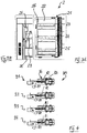
- the mechanical lock assembly which is operable by a respective solenoid for locking and unlocking a respective access member may comprise components such as shown in Fig. 4 .
- the mechanical lock assembly 80 according to Fig. 4 comprises at least one pin 83, at least one hook 81 operated by the pin and at least one spring 82 coupled with the pin.
- the mechanical lock assembly comprises several components which interact as follows: The involved components as shown in Fig.4 are the hook 81, a push-spring 82, the pin 83, this is the 'shaft' of the solenoid, and a pull-spring 84 (not visible) connecting the pin 83 and the hook 81.
- the solenoid needs an electrical pulse only for the move from locked to unlocked position or from unlocked to locked position. If the mechanism is in the locked-position, the solenoid is in the position as mentioned in the first picture of Fig. 4 (situation 91), a static magnet (not shown) keeps the pin and the complete mechanism in this position (no current supply required). So, in this position the static magnet is stronger than the push-spring 82.
- the solenoid is in the position as shown in the second picture of Fig. 4 (situation 92), the push-spring 82 keeps the pin 83 and the complete mechanism in this position (no current supply required). So, in this position the push-spring 82 is stronger than the static magnet. The pull-spring 84 will only be stretched if the mechanism is locked and the door will be closed afterwards. This is shown in the third picture of Fig. 4 (situation 93). The position in situation 94 equals the position in situation 91. In this way, the springs of the mechanical lock assembly make it possible to close the access member even when the hook is already in the locked position.
Landscapes
- Physics & Mathematics (AREA)
- Engineering & Computer Science (AREA)
- Thermal Sciences (AREA)
- Electromagnetism (AREA)
- Chemical & Material Sciences (AREA)
- Combustion & Propulsion (AREA)
- Mechanical Engineering (AREA)
- General Engineering & Computer Science (AREA)
- Lock And Its Accessories (AREA)
Claims (10)
- System (10), das mehrere gekühlte Lagerungsvorrichtungen (1, 2, 3, 4, 5) zum Lagern von Waren, die eine Kühlung erfordern, umfasst, wobei das System Folgendes umfasst:- wenigstens eine erste gekühlte Lagerungsvorrichtung (1), die für die Lagerung von Waren in einem Lagerungsraum (12) eines ersten Gehäuses (11) ausgelegt ist, wobei die erste Lagerungsvorrichtung wenigstens ein erstes Zugriffselement (13) umfasst, das verriegelt und entriegelt werden kann, um einen Zugriff auf den Lagerungsraum des ersten Gehäuses bereitzustellen,- wenigstens eine zweite gekühlte Lagerungsvorrichtung (2), die für die Lagerung von Waren in einem Lagerungsraum (22) eines zweiten Gehäuses (21) ausgelegt ist, wobei die zweite Lagerungsvorrichtung wenigstens ein zweites Zugriffselement (23-25) umfasst, das verriegelt und entriegelt werden kann, um einen Zugriff auf den Lagerungsraum des zweiten Gehäuses bereitzustellen,- wobei die erste gekühlte Lagerungsvorrichtung (1) eine erste Verriegelungsvorrichtung (16, 80) umfasst, die zum Verriegeln und Entriegeln des ersten Zugriffselements (13) betätigt werden kann,- wobei die zweite gekühlte Lagerungsvorrichtung (2) eine zweite Verriegelungsvorrichtung (26, 28, 29, 80) umfasst, die zum Verriegeln und Entriegeln des zweiten Zugriffselements (23-25) betätigt werden kann, wobei die erste und die zweite gekühlte Verriegelungsvorrichtung (16, 26, 28, 29, 80) durch einen Magnetschalter (26) betätigt werden,- wobei die erste Verriegelungsvorrichtung (16, 80) durch Tastenmittel zum Verriegeln und Entriegeln der ersten Verriegelungsvorrichtung betätigt werden kann,gekennzeichnet durch
eine Kopplungsvorrichtung (61), die mit der ersten Verriegelungsvorrichtung (16, 80) verbunden ist und ausgelegt ist, mit der zweiten Verriegelungsvorrichtung verbunden zu werden;
wobei die erste gekühlte Lagerungsvorrichtung (1, 2, 3, 4, 5) und die zweite gekühlte Lagerungsvorrichtung (1, 2, 3, 4, 5) als modulare Lagerungssegmente ausgelegt sind, die jeweils als selbsttragende Lagerungsbehälter ausgebildet sind, die über ihre jeweilige Kopplungsvorrichtung (61) so miteinander gekoppelt sind, dass die erste gekühlte Lagerungsvorrichtung und die zweite gekühlte Lagerungsvorrichtung unabhängig voneinander bewegt werden können, und dann, wenn sie miteinander gekoppelt sind, die erste Verriegelungsvorrichtung betätigt werden kann, um den Magnetschalter der zweiten Verriegelungsvorrichtung durch die Kopplungsvorrichtung (61) auszulösen. - System (10) nach Anspruch 1, wobei die Kopplungsvorrichtung (61) an der Umfangsfläche (17, 18) der ersten und/oder der zweiten Lagerungsvorrichtung (1, 2) so angeordnet ist, dass die erste und die zweite Lagerungsvorrichtung so ausgelegt sind, dass sie nebeneinander angeordnet sind.
- System (10) nach Anspruch 2, wobei die entsprechenden Kopplungsvorrichtungen (61) der ersten und der zweiten Lagerungsvorrichtung für eine Verbindung miteinander einander gegenüberliegen.
- System (10) nach einem der vorhergehenden Ansprüche, wobei die wenigstens eine Kopplungsvorrichtung wenigstens eine Vorrichtung (61) zum Bereitstellen einer drahtgebundenen elektrischen Verbindung, einer drahtlosen elektrischen Verbindung, einer magnetischen Verbindung und/oder einer mechanischen Verbindung zwischen der ersten und der zweiten Lagerungsvorrichtung (1, 2) umfasst.
- System (10) nach einem der Ansprüche 1 bis 4, wobei die erste und/oder die zweite Lagerungsvorrichtung (1, 2) als ein Kühlgehäuse oder ein Kühlthekenbehälter ausgebildet sind.
- System (10) nach einem der Ansprüche 1 bis 5, wobei das erste und/oder das zweite Zugriffselement eine Tür (13) oder eine Schublade (23-25) umfasst, die durch eine jeweilige Verriegelungsvorrichtung (16, 26, 28, 29, 80) verriegelt und entriegelt wird.
- System (10) nach einem der Ansprüche 1 bis 6, wobei die erste und die zweite Lagerungsvorrichtung (1, 2) ausgelegt sind, eine Lagerungsmodulanordnung (10) zu bilden, die eine im Wesentlichen einheitliche Zugriffsfront aufweist.
- System (10) nach einem der Ansprüche 1 bis 7, wobei die erste und/oder die zweite Verriegelungsvorrichtung (16, 26, 28, 29, 80) einen elektrisch betätigten Tastenschalter umfasst.
- System (10) nach einem der vorhergehenden Ansprüche, wobei die erste und/oder die zweite Verriegelungsvorrichtung wenigstes einen bistabilen Magnetschalter (26) und wenigstens eine mechanische Verriegelungsanordnung (28, 29, 80) umfasst, die durch den Magnetschalter zum Verriegeln und Entriegeln des jeweiligen Zugriffselements betätigt werden können.
- System (10) nach Anspruch 9, wobei die mechanische Verriegelungsanordnung wenigstens einen Stift (83), wenigstens einen Haken (81), der durch den Stift betätigt wird, und wenigstens eine Feder (82), die mit dem Stift gekoppelt ist, umfasst, wobei die wenigstens eine Feder (82) ausgelegt ist, den Haken (81) in eine Verriegelungsposition vorzubelasten, um das Zugriffselement zu verriegeln, wenn sich das Zugriffselement in die geschlossene Position bewegt.
Applications Claiming Priority (1)
| Application Number | Priority Date | Filing Date | Title |
|---|---|---|---|
| PCT/EP2008/000013 WO2009083040A1 (en) | 2008-01-02 | 2008-01-02 | System for storing of goods requiring refrigeration and storage device adapted for use in such system |
Publications (2)
| Publication Number | Publication Date |
|---|---|
| EP2240730A1 EP2240730A1 (de) | 2010-10-20 |
| EP2240730B1 true EP2240730B1 (de) | 2018-07-18 |
Family
ID=39817098
Family Applications (1)
| Application Number | Title | Priority Date | Filing Date |
|---|---|---|---|
| EP08700970.0A Active EP2240730B1 (de) | 2008-01-02 | 2008-01-02 | System zum lagern von kühlung erfordernden waren und zur verwendung in solch einem system ausgeführte lagerungsvorrichtung |
Country Status (2)
| Country | Link |
|---|---|
| EP (1) | EP2240730B1 (de) |
| WO (1) | WO2009083040A1 (de) |
Families Citing this family (1)
| Publication number | Priority date | Publication date | Assignee | Title |
|---|---|---|---|---|
| IT201600098545A1 (it) * | 2016-09-30 | 2018-03-30 | Clabo Spa | Cerniera per ante. |
Family Cites Families (9)
| Publication number | Priority date | Publication date | Assignee | Title |
|---|---|---|---|---|
| DE3114980A1 (de) * | 1981-04-14 | 1982-10-28 | Philipp Kirsch GmbH, 7600 Offenburg | Kuehlschrank |
| DE8704719U1 (de) | 1987-03-31 | 1987-07-02 | Herbrecht, Harald, 8000 München | Vorrichtung zur diebstahlsicheren Aufnahme und Kühlung von Gegenständen |
| FR2689221A1 (fr) * | 1992-03-27 | 1993-10-01 | Crost Alain | Consigne réfrigérante multi-compartiments. |
| AU1237801A (en) * | 1999-10-28 | 2001-05-08 | Brivo Systems, Inc. | Systems and devices for unattended transfer of items |
| DE19958683A1 (de) * | 1999-12-06 | 2001-06-07 | Antonius Reittinger | Fernbedienbares Lagerungsbehältnis und Betriebsverfahren hierfür |
| DE19963532C1 (de) * | 1999-12-20 | 2001-03-01 | Dirk Schiebel | Behälter zum Einbau in eine Kühlvorrichtung, insbesondere in einen Haushaltskühlschrank |
| JP2004085194A (ja) * | 2002-08-23 | 2004-03-18 | Samsung Electronics Co Ltd | 組立式冷蔵庫 |
| DE102004006281A1 (de) * | 2004-02-09 | 2005-08-25 | Linde Kältetechnik GmbH & Co. KG | Modular aufgebautes Kühlmöbel |
| EP1977176B1 (de) * | 2005-12-30 | 2009-11-25 | Arcelik Anonim Sirketi | Kühlvorrichtung |
-
2008
- 2008-01-02 EP EP08700970.0A patent/EP2240730B1/de active Active
- 2008-01-02 WO PCT/EP2008/000013 patent/WO2009083040A1/en not_active Ceased
Non-Patent Citations (1)
| Title |
|---|
| None * |
Also Published As
| Publication number | Publication date |
|---|---|
| WO2009083040A1 (en) | 2009-07-09 |
| EP2240730A1 (de) | 2010-10-20 |
Similar Documents
| Publication | Publication Date | Title |
|---|---|---|
| US8419083B2 (en) | Electromechanical locks and latching arrangements | |
| AU2010313163B2 (en) | Safe with dual locking mechanism | |
| US9157261B2 (en) | Multifunction latch assembly | |
| EP2480740B1 (de) | Absperrbares gehäuse | |
| JP6379102B2 (ja) | ハンドル組立体 | |
| US20150048625A1 (en) | Electromechanical lock for cabinets, showcases and drawers | |
| US9016095B2 (en) | Multiple user lockbox | |
| US10858863B2 (en) | Self-locking lock for merchandise security | |
| US20120000255A1 (en) | Lockable enclosure with loading cartridge | |
| CN111425074B (zh) | 储物柜 | |
| US20150077232A1 (en) | Near field communication devices for merchandise security | |
| EP2240730B1 (de) | System zum lagern von kühlung erfordernden waren und zur verwendung in solch einem system ausgeführte lagerungsvorrichtung | |
| US20180023321A1 (en) | Cabinet lock for merchandise security | |
| US20150061831A1 (en) | Key and security device | |
| US11401732B2 (en) | Modular lock mechanism | |
| KR102440481B1 (ko) | 캐비닛용 잠금 장치 | |
| EP1977176B1 (de) | Kühlvorrichtung | |
| DK2684179T3 (en) | Theft Intercom | |
| JPH0432465Y2 (de) | ||
| WO2008041908A1 (en) | Lock device | |
| CN112211497A (zh) | 电子锁的控制方法及储物柜 | |
| WO2015038201A1 (en) | Multi-purpose key for security devices | |
| US11988019B2 (en) | Drawer lock device | |
| JP2022075216A (ja) | 収納什器 | |
| WO2018089767A1 (en) | Hidden lock for merchandise security |
Legal Events
| Date | Code | Title | Description |
|---|---|---|---|
| PUAI | Public reference made under article 153(3) epc to a published international application that has entered the european phase |
Free format text: ORIGINAL CODE: 0009012 |
|
| 17P | Request for examination filed |
Effective date: 20100722 |
|
| AK | Designated contracting states |
Kind code of ref document: A1 Designated state(s): AT BE BG CH CY CZ DE DK EE ES FI FR GB GR HR HU IE IS IT LI LT LU LV MC MT NL NO PL PT RO SE SI SK TR |
|
| DAX | Request for extension of the european patent (deleted) | ||
| 17Q | First examination report despatched |
Effective date: 20131106 |
|
| RAP1 | Party data changed (applicant data changed or rights of an application transferred) |
Owner name: ILLINOIS TOOL WORKS INC. |
|
| STAA | Information on the status of an ep patent application or granted ep patent |
Free format text: STATUS: EXAMINATION IS IN PROGRESS |
|
| REG | Reference to a national code |
Ref country code: DE Ref legal event code: R079 Ref document number: 602008056044 Country of ref document: DE Free format text: PREVIOUS MAIN CLASS: F25D0013020000 Ipc: E05B0047000000 |
|
| RIC1 | Information provided on ipc code assigned before grant |
Ipc: E05B 47/00 20060101AFI20170619BHEP Ipc: E05B 47/02 20060101ALI20170619BHEP Ipc: F25D 13/02 20060101ALI20170619BHEP Ipc: E05B 65/00 20060101ALI20170619BHEP |
|
| GRAP | Despatch of communication of intention to grant a patent |
Free format text: ORIGINAL CODE: EPIDOSNIGR1 |
|
| STAA | Information on the status of an ep patent application or granted ep patent |
Free format text: STATUS: GRANT OF PATENT IS INTENDED |
|
| INTG | Intention to grant announced |
Effective date: 20170906 |
|
| GRAS | Grant fee paid |
Free format text: ORIGINAL CODE: EPIDOSNIGR3 |
|
| GRAJ | Information related to disapproval of communication of intention to grant by the applicant or resumption of examination proceedings by the epo deleted |
Free format text: ORIGINAL CODE: EPIDOSDIGR1 |
|
| GRAL | Information related to payment of fee for publishing/printing deleted |
Free format text: ORIGINAL CODE: EPIDOSDIGR3 |
|
| STAA | Information on the status of an ep patent application or granted ep patent |
Free format text: STATUS: EXAMINATION IS IN PROGRESS |
|
| GRAP | Despatch of communication of intention to grant a patent |
Free format text: ORIGINAL CODE: EPIDOSNIGR1 |
|
| STAA | Information on the status of an ep patent application or granted ep patent |
Free format text: STATUS: GRANT OF PATENT IS INTENDED |
|
| INTC | Intention to grant announced (deleted) | ||
| INTG | Intention to grant announced |
Effective date: 20180124 |
|
| GRAA | (expected) grant |
Free format text: ORIGINAL CODE: 0009210 |
|
| STAA | Information on the status of an ep patent application or granted ep patent |
Free format text: STATUS: THE PATENT HAS BEEN GRANTED |
|
| AK | Designated contracting states |
Kind code of ref document: B1 Designated state(s): AT BE BG CH CY CZ DE DK EE ES FI FR GB GR HR HU IE IS IT LI LT LU LV MC MT NL NO PL PT RO SE SI SK TR |
|
| REG | Reference to a national code |
Ref country code: GB Ref legal event code: FG4D |
|
| RIN1 | Information on inventor provided before grant (corrected) |
Inventor name: NAAIJKENS, PETER Inventor name: DE WILD, PIET |
|
| REG | Reference to a national code |
Ref country code: CH Ref legal event code: EP |
|
| REG | Reference to a national code |
Ref country code: IE Ref legal event code: FG4D |
|
| REG | Reference to a national code |
Ref country code: AT Ref legal event code: REF Ref document number: 1019539 Country of ref document: AT Kind code of ref document: T Effective date: 20180815 |
|
| REG | Reference to a national code |
Ref country code: DE Ref legal event code: R096 Ref document number: 602008056044 Country of ref document: DE |
|
| REG | Reference to a national code |
Ref country code: NL Ref legal event code: FP |
|
| REG | Reference to a national code |
Ref country code: LT Ref legal event code: MG4D |
|
| REG | Reference to a national code |
Ref country code: AT Ref legal event code: MK05 Ref document number: 1019539 Country of ref document: AT Kind code of ref document: T Effective date: 20180718 |
|
| PG25 | Lapsed in a contracting state [announced via postgrant information from national office to epo] |
Ref country code: BG Free format text: LAPSE BECAUSE OF FAILURE TO SUBMIT A TRANSLATION OF THE DESCRIPTION OR TO PAY THE FEE WITHIN THE PRESCRIBED TIME-LIMIT Effective date: 20181018 Ref country code: AT Free format text: LAPSE BECAUSE OF FAILURE TO SUBMIT A TRANSLATION OF THE DESCRIPTION OR TO PAY THE FEE WITHIN THE PRESCRIBED TIME-LIMIT Effective date: 20180718 Ref country code: GR Free format text: LAPSE BECAUSE OF FAILURE TO SUBMIT A TRANSLATION OF THE DESCRIPTION OR TO PAY THE FEE WITHIN THE PRESCRIBED TIME-LIMIT Effective date: 20181019 Ref country code: NO Free format text: LAPSE BECAUSE OF FAILURE TO SUBMIT A TRANSLATION OF THE DESCRIPTION OR TO PAY THE FEE WITHIN THE PRESCRIBED TIME-LIMIT Effective date: 20181018 Ref country code: IS Free format text: LAPSE BECAUSE OF FAILURE TO SUBMIT A TRANSLATION OF THE DESCRIPTION OR TO PAY THE FEE WITHIN THE PRESCRIBED TIME-LIMIT Effective date: 20181118 Ref country code: LT Free format text: LAPSE BECAUSE OF FAILURE TO SUBMIT A TRANSLATION OF THE DESCRIPTION OR TO PAY THE FEE WITHIN THE PRESCRIBED TIME-LIMIT Effective date: 20180718 Ref country code: FI Free format text: LAPSE BECAUSE OF FAILURE TO SUBMIT A TRANSLATION OF THE DESCRIPTION OR TO PAY THE FEE WITHIN THE PRESCRIBED TIME-LIMIT Effective date: 20180718 Ref country code: SE Free format text: LAPSE BECAUSE OF FAILURE TO SUBMIT A TRANSLATION OF THE DESCRIPTION OR TO PAY THE FEE WITHIN THE PRESCRIBED TIME-LIMIT Effective date: 20180718 Ref country code: PL Free format text: LAPSE BECAUSE OF FAILURE TO SUBMIT A TRANSLATION OF THE DESCRIPTION OR TO PAY THE FEE WITHIN THE PRESCRIBED TIME-LIMIT Effective date: 20180718 |
|
| PG25 | Lapsed in a contracting state [announced via postgrant information from national office to epo] |
Ref country code: LV Free format text: LAPSE BECAUSE OF FAILURE TO SUBMIT A TRANSLATION OF THE DESCRIPTION OR TO PAY THE FEE WITHIN THE PRESCRIBED TIME-LIMIT Effective date: 20180718 Ref country code: HR Free format text: LAPSE BECAUSE OF FAILURE TO SUBMIT A TRANSLATION OF THE DESCRIPTION OR TO PAY THE FEE WITHIN THE PRESCRIBED TIME-LIMIT Effective date: 20180718 Ref country code: ES Free format text: LAPSE BECAUSE OF FAILURE TO SUBMIT A TRANSLATION OF THE DESCRIPTION OR TO PAY THE FEE WITHIN THE PRESCRIBED TIME-LIMIT Effective date: 20180718 |
|
| REG | Reference to a national code |
Ref country code: DE Ref legal event code: R097 Ref document number: 602008056044 Country of ref document: DE |
|
| PG25 | Lapsed in a contracting state [announced via postgrant information from national office to epo] |
Ref country code: EE Free format text: LAPSE BECAUSE OF FAILURE TO SUBMIT A TRANSLATION OF THE DESCRIPTION OR TO PAY THE FEE WITHIN THE PRESCRIBED TIME-LIMIT Effective date: 20180718 Ref country code: CZ Free format text: LAPSE BECAUSE OF FAILURE TO SUBMIT A TRANSLATION OF THE DESCRIPTION OR TO PAY THE FEE WITHIN THE PRESCRIBED TIME-LIMIT Effective date: 20180718 Ref country code: RO Free format text: LAPSE BECAUSE OF FAILURE TO SUBMIT A TRANSLATION OF THE DESCRIPTION OR TO PAY THE FEE WITHIN THE PRESCRIBED TIME-LIMIT Effective date: 20180718 Ref country code: IT Free format text: LAPSE BECAUSE OF FAILURE TO SUBMIT A TRANSLATION OF THE DESCRIPTION OR TO PAY THE FEE WITHIN THE PRESCRIBED TIME-LIMIT Effective date: 20180718 |
|
| PLBE | No opposition filed within time limit |
Free format text: ORIGINAL CODE: 0009261 |
|
| STAA | Information on the status of an ep patent application or granted ep patent |
Free format text: STATUS: NO OPPOSITION FILED WITHIN TIME LIMIT |
|
| PG25 | Lapsed in a contracting state [announced via postgrant information from national office to epo] |
Ref country code: SK Free format text: LAPSE BECAUSE OF FAILURE TO SUBMIT A TRANSLATION OF THE DESCRIPTION OR TO PAY THE FEE WITHIN THE PRESCRIBED TIME-LIMIT Effective date: 20180718 Ref country code: DK Free format text: LAPSE BECAUSE OF FAILURE TO SUBMIT A TRANSLATION OF THE DESCRIPTION OR TO PAY THE FEE WITHIN THE PRESCRIBED TIME-LIMIT Effective date: 20180718 |
|
| 26N | No opposition filed |
Effective date: 20190423 |
|
| REG | Reference to a national code |
Ref country code: DE Ref legal event code: R119 Ref document number: 602008056044 Country of ref document: DE |
|
| PG25 | Lapsed in a contracting state [announced via postgrant information from national office to epo] |
Ref country code: SI Free format text: LAPSE BECAUSE OF FAILURE TO SUBMIT A TRANSLATION OF THE DESCRIPTION OR TO PAY THE FEE WITHIN THE PRESCRIBED TIME-LIMIT Effective date: 20180718 Ref country code: MC Free format text: LAPSE BECAUSE OF FAILURE TO SUBMIT A TRANSLATION OF THE DESCRIPTION OR TO PAY THE FEE WITHIN THE PRESCRIBED TIME-LIMIT Effective date: 20180718 |
|
| REG | Reference to a national code |
Ref country code: CH Ref legal event code: PL |
|
| PG25 | Lapsed in a contracting state [announced via postgrant information from national office to epo] |
Ref country code: LU Free format text: LAPSE BECAUSE OF NON-PAYMENT OF DUE FEES Effective date: 20190102 |
|
| REG | Reference to a national code |
Ref country code: BE Ref legal event code: MM Effective date: 20190131 |
|
| REG | Reference to a national code |
Ref country code: IE Ref legal event code: MM4A |
|
| PG25 | Lapsed in a contracting state [announced via postgrant information from national office to epo] |
Ref country code: DE Free format text: LAPSE BECAUSE OF NON-PAYMENT OF DUE FEES Effective date: 20190801 |
|
| PG25 | Lapsed in a contracting state [announced via postgrant information from national office to epo] |
Ref country code: BE Free format text: LAPSE BECAUSE OF NON-PAYMENT OF DUE FEES Effective date: 20190131 |
|
| PG25 | Lapsed in a contracting state [announced via postgrant information from national office to epo] |
Ref country code: LI Free format text: LAPSE BECAUSE OF NON-PAYMENT OF DUE FEES Effective date: 20190131 Ref country code: CH Free format text: LAPSE BECAUSE OF NON-PAYMENT OF DUE FEES Effective date: 20190131 |
|
| PG25 | Lapsed in a contracting state [announced via postgrant information from national office to epo] |
Ref country code: IE Free format text: LAPSE BECAUSE OF NON-PAYMENT OF DUE FEES Effective date: 20190102 |
|
| PG25 | Lapsed in a contracting state [announced via postgrant information from national office to epo] |
Ref country code: TR Free format text: LAPSE BECAUSE OF FAILURE TO SUBMIT A TRANSLATION OF THE DESCRIPTION OR TO PAY THE FEE WITHIN THE PRESCRIBED TIME-LIMIT Effective date: 20180718 |
|
| PG25 | Lapsed in a contracting state [announced via postgrant information from national office to epo] |
Ref country code: PT Free format text: LAPSE BECAUSE OF FAILURE TO SUBMIT A TRANSLATION OF THE DESCRIPTION OR TO PAY THE FEE WITHIN THE PRESCRIBED TIME-LIMIT Effective date: 20181118 Ref country code: MT Free format text: LAPSE BECAUSE OF NON-PAYMENT OF DUE FEES Effective date: 20190102 |
|
| PG25 | Lapsed in a contracting state [announced via postgrant information from national office to epo] |
Ref country code: CY Free format text: LAPSE BECAUSE OF FAILURE TO SUBMIT A TRANSLATION OF THE DESCRIPTION OR TO PAY THE FEE WITHIN THE PRESCRIBED TIME-LIMIT Effective date: 20180718 |
|
| PG25 | Lapsed in a contracting state [announced via postgrant information from national office to epo] |
Ref country code: HU Free format text: LAPSE BECAUSE OF FAILURE TO SUBMIT A TRANSLATION OF THE DESCRIPTION OR TO PAY THE FEE WITHIN THE PRESCRIBED TIME-LIMIT; INVALID AB INITIO Effective date: 20080102 |
|
| P01 | Opt-out of the competence of the unified patent court (upc) registered |
Effective date: 20230606 |
|
| PGFP | Annual fee paid to national office [announced via postgrant information from national office to epo] |
Ref country code: NL Payment date: 20260126 Year of fee payment: 19 |
|
| PGFP | Annual fee paid to national office [announced via postgrant information from national office to epo] |
Ref country code: GB Payment date: 20260127 Year of fee payment: 19 |
|
| PGFP | Annual fee paid to national office [announced via postgrant information from national office to epo] |
Ref country code: FR Payment date: 20260126 Year of fee payment: 19 |