EP2240728B1 - Photovoltaik-moduleinrichtung - Google Patents
Photovoltaik-moduleinrichtung Download PDFInfo
- Publication number
- EP2240728B1 EP2240728B1 EP20080860405 EP08860405A EP2240728B1 EP 2240728 B1 EP2240728 B1 EP 2240728B1 EP 20080860405 EP20080860405 EP 20080860405 EP 08860405 A EP08860405 A EP 08860405A EP 2240728 B1 EP2240728 B1 EP 2240728B1
- Authority
- EP
- European Patent Office
- Prior art keywords
- unit
- photovoltaic
- photovoltaic module
- module device
- transverse edge
- Prior art date
- Legal status (The legal status is an assumption and is not a legal conclusion. Google has not performed a legal analysis and makes no representation as to the accuracy of the status listed.)
- Not-in-force
Links
Images


Classifications
-
- H—ELECTRICITY
- H02—GENERATION; CONVERSION OR DISTRIBUTION OF ELECTRIC POWER
- H02S—GENERATION OF ELECTRIC POWER BY CONVERSION OF INFRARED RADIATION, VISIBLE LIGHT OR ULTRAVIOLET LIGHT, e.g. USING PHOTOVOLTAIC [PV] MODULES
- H02S20/00—Supporting structures for PV modules
- H02S20/20—Supporting structures directly fixed to an immovable object
- H02S20/22—Supporting structures directly fixed to an immovable object specially adapted for buildings
- H02S20/23—Supporting structures directly fixed to an immovable object specially adapted for buildings specially adapted for roof structures
-
- F—MECHANICAL ENGINEERING; LIGHTING; HEATING; WEAPONS; BLASTING
- F24—HEATING; RANGES; VENTILATING
- F24S—SOLAR HEAT COLLECTORS; SOLAR HEAT SYSTEMS
- F24S20/00—Solar heat collectors specially adapted for particular uses or environments
- F24S20/60—Solar heat collectors integrated in fixed constructions, e.g. in buildings
- F24S20/67—Solar heat collectors integrated in fixed constructions, e.g. in buildings in the form of roof constructions
-
- F—MECHANICAL ENGINEERING; LIGHTING; HEATING; WEAPONS; BLASTING
- F24—HEATING; RANGES; VENTILATING
- F24S—SOLAR HEAT COLLECTORS; SOLAR HEAT SYSTEMS
- F24S25/00—Arrangement of stationary mountings or supports for solar heat collector modules
- F24S25/20—Peripheral frames for modules
-
- H—ELECTRICITY
- H10—SEMICONDUCTOR DEVICES; ELECTRIC SOLID-STATE DEVICES NOT OTHERWISE PROVIDED FOR
- H10F—INORGANIC SEMICONDUCTOR DEVICES SENSITIVE TO INFRARED RADIATION, LIGHT, ELECTROMAGNETIC RADIATION OF SHORTER WAVELENGTH OR CORPUSCULAR RADIATION
- H10F19/00—Integrated devices, or assemblies of multiple devices, comprising at least one photovoltaic cell covered by group H10F10/00, e.g. photovoltaic modules
- H10F19/90—Structures for connecting between photovoltaic cells, e.g. interconnections or insulating spacers
-
- H—ELECTRICITY
- H10—SEMICONDUCTOR DEVICES; ELECTRIC SOLID-STATE DEVICES NOT OTHERWISE PROVIDED FOR
- H10F—INORGANIC SEMICONDUCTOR DEVICES SENSITIVE TO INFRARED RADIATION, LIGHT, ELECTROMAGNETIC RADIATION OF SHORTER WAVELENGTH OR CORPUSCULAR RADIATION
- H10F77/00—Constructional details of devices covered by this subclass
- H10F77/95—Circuit arrangements
- H10F77/953—Circuit arrangements for devices having potential barriers
- H10F77/955—Circuit arrangements for devices having potential barriers for photovoltaic devices
-
- F—MECHANICAL ENGINEERING; LIGHTING; HEATING; WEAPONS; BLASTING
- F24—HEATING; RANGES; VENTILATING
- F24S—SOLAR HEAT COLLECTORS; SOLAR HEAT SYSTEMS
- F24S20/00—Solar heat collectors specially adapted for particular uses or environments
- F24S2020/10—Solar modules layout; Modular arrangements
- F24S2020/13—Overlaying arrangements similar to roof tiles
-
- Y—GENERAL TAGGING OF NEW TECHNOLOGICAL DEVELOPMENTS; GENERAL TAGGING OF CROSS-SECTIONAL TECHNOLOGIES SPANNING OVER SEVERAL SECTIONS OF THE IPC; TECHNICAL SUBJECTS COVERED BY FORMER USPC CROSS-REFERENCE ART COLLECTIONS [XRACs] AND DIGESTS
- Y02—TECHNOLOGIES OR APPLICATIONS FOR MITIGATION OR ADAPTATION AGAINST CLIMATE CHANGE
- Y02B—CLIMATE CHANGE MITIGATION TECHNOLOGIES RELATED TO BUILDINGS, e.g. HOUSING, HOUSE APPLIANCES OR RELATED END-USER APPLICATIONS
- Y02B10/00—Integration of renewable energy sources in buildings
- Y02B10/10—Photovoltaic [PV]
-
- Y—GENERAL TAGGING OF NEW TECHNOLOGICAL DEVELOPMENTS; GENERAL TAGGING OF CROSS-SECTIONAL TECHNOLOGIES SPANNING OVER SEVERAL SECTIONS OF THE IPC; TECHNICAL SUBJECTS COVERED BY FORMER USPC CROSS-REFERENCE ART COLLECTIONS [XRACs] AND DIGESTS
- Y02—TECHNOLOGIES OR APPLICATIONS FOR MITIGATION OR ADAPTATION AGAINST CLIMATE CHANGE
- Y02B—CLIMATE CHANGE MITIGATION TECHNOLOGIES RELATED TO BUILDINGS, e.g. HOUSING, HOUSE APPLIANCES OR RELATED END-USER APPLICATIONS
- Y02B10/00—Integration of renewable energy sources in buildings
- Y02B10/20—Solar thermal
-
- Y—GENERAL TAGGING OF NEW TECHNOLOGICAL DEVELOPMENTS; GENERAL TAGGING OF CROSS-SECTIONAL TECHNOLOGIES SPANNING OVER SEVERAL SECTIONS OF THE IPC; TECHNICAL SUBJECTS COVERED BY FORMER USPC CROSS-REFERENCE ART COLLECTIONS [XRACs] AND DIGESTS
- Y02—TECHNOLOGIES OR APPLICATIONS FOR MITIGATION OR ADAPTATION AGAINST CLIMATE CHANGE
- Y02E—REDUCTION OF GREENHOUSE GAS [GHG] EMISSIONS, RELATED TO ENERGY GENERATION, TRANSMISSION OR DISTRIBUTION
- Y02E10/00—Energy generation through renewable energy sources
- Y02E10/40—Solar thermal energy, e.g. solar towers
- Y02E10/47—Mountings or tracking
-
- Y—GENERAL TAGGING OF NEW TECHNOLOGICAL DEVELOPMENTS; GENERAL TAGGING OF CROSS-SECTIONAL TECHNOLOGIES SPANNING OVER SEVERAL SECTIONS OF THE IPC; TECHNICAL SUBJECTS COVERED BY FORMER USPC CROSS-REFERENCE ART COLLECTIONS [XRACs] AND DIGESTS
- Y02—TECHNOLOGIES OR APPLICATIONS FOR MITIGATION OR ADAPTATION AGAINST CLIMATE CHANGE
- Y02E—REDUCTION OF GREENHOUSE GAS [GHG] EMISSIONS, RELATED TO ENERGY GENERATION, TRANSMISSION OR DISTRIBUTION
- Y02E10/00—Energy generation through renewable energy sources
- Y02E10/50—Photovoltaic [PV] energy
Definitions
- the present invention relates to a photovoltaic module device having a supporting structure for photovoltaic units.
- photovoltaic module devices in a variety of construction.
- the individual photovoltaic modules are mounted on a roof and electrically interconnected. This means a relatively high installation effort and also requires a dense roof area.
- From the DE 10 2005 029 465 A1 discloses a device and method for heat energy supply of a building having a solar panels consisting of solar system, which is spaced to a substructure of the building, for example roof or facade construction, is arranged, which is characterized in that between the bottom of the solar system and the top of the substructure existing air space volume is designed as a closed volume with at least one air inlet and at least one air outlet, said air volume is supplied to a hot air utilization device, which converts the heat energy present in the room air volume and makes usable for the building.
- Photovoltaic module devices are described with a support structure for photovoltaic units, which are arranged side by side and behind each other.
- the support structure in this case has a modular frame support structure, wherein the frame structure units are arranged side by side and behind each other and form a closed surface together with the photovoltaic units.
- sealing units are present between the frame structural units.
- the present invention the object or the technical problem of specifying a photovoltaic module device, which is able to be formed as a whole, liquid-tight roof or facade surface, which can be easily mounted, the ensures a permanently reliable function and ensures a high degree of variability with regard to the geometry to be observed in each case on the structure, with the aim in particular being that in constructive simple and reliable way to form the entire roof or facade surface as a photovoltaic system without consuming additional sealing work on the roof or facade construction are required.
- the photovoltaic module device according to the invention should be economical to produce, so that the respective builder an effective and cost-effective solution for electrical energy generation can be provided.
- the photovoltaic module device according to the invention is given by the features of independent claim 1.
- the photovoltaic module device is characterized mutatis mutandis by the fact that the support structure has a modular frame support structure, wherein the frame support structure has at least two spaced sidewall support on which a photovoltaic unit is incorporated liquid-tight, a first transverse edge support and a spaced from the first transverse edge support second transverse edge support has and the photovoltaic unit is provided with a projection projecting beyond the first transverse edge support, such that the photovoltaic units can overlap adjacently arranged frame support units.
- the module device is formed in a simple manner as a frame support structure unit, the respective individual compassionrag Jardinen can easily be joined together during assembly and overall create a "waterproof" surface, be it a roof or facade surface.
- a protrusion between the photovoltaic units of adjacent frame structural units, penetration of liquids, especially rainwater due to the vertical or inclined arrangement of the module devices, from the outset is not possible.
- the photovoltaic module device Due to the simple structure of the photovoltaic module device according to the invention, this can be produced economically, ensures easy installation and thus represents the respective client a lucrative opportunity to secure the energy supply for a building. In addition, he can by the Inventive photovoltaic module device feed energy generated in the event of a surplus in a network, which brings him additional financial benefits, since the utilities must compensate for this additional input electrical energy.
- old Eternit (registered trademark) roofing can be replaced by the photovoltaic module device according to the invention, in particular without additional roofing measures are necessary.
- the photovoltaic module device according to the invention it is possible to produce closed roof or facade surfaces without the need for additional measures for the roof or facade covering.
- a particularly advantageous embodiment of the photovoltaic module device according to the invention is characterized in that the modular frame support structure unit is designed as an orthogonal quadrangular unit, in particular a rectangular or square unit.
- the modular frame support structure unit is designed as an orthogonal quadrangular unit, in particular a rectangular or square unit.
- the choice of this simple peripheral contour ensures easy handling during assembly and also during production. Further polygonal peripheral structures (for example triangular contours) are possible without any problem.
- a structurally particularly simple and therefore also preferred embodiment is characterized in that the side bolsters have a projection unit in the region above the first transverse edge support and a return unit in the region above the second transverse edge support, such that the same cross-sectional height of the side wall support as adjacent adjacent frame structural units in the rest of the same range, that is, the projection unit has substantially the same circumferential contour as the return unit.
- a preferred embodiment of the photovoltaic module device according to the invention is characterized in that in the region of the first and / or second transverse edge support a sealing unit is arranged, which seals adjacent adjacent frame structural units and photovoltaic units liquid-tight against each other.
- a particularly preferred embodiment with respect to the liquid seal is characterized in that the photovoltaic unit is inclined relative to the plane of the frame support unit, one in this sense structurally particularly simple development is characterized in that the end edge regions of the photovoltaic unit is arranged above the first transverse edge support or the second transverse edge support, which also increases the stability of the module device.
- a particularly advantageous embodiment is characterized in that below the photovoltaic unit connection options exist to install a thermal insulation.
- This can be implemented, for example, in that the side bolsters have on the inside a first groove into which, for example, a glass pane can be inserted.
- the insulation value of the photovoltaic module device according to the invention increases significantly.
- a structurally particularly advantageous embodiment which ensures a compact wiring of the individual photovoltaic module devices with each other, is characterized in that the side bolsters inside and / or outside grooves have, in which electrical cables can be laid without any problems, for electrical communication of adjacent photovoltaics Module devices serve and are supplied as a result of a central control unit, which analyzes the current energy situation, evaluates and uses.
- a structurally particularly simple, economic production and a permanently reliable function ensuring advantageous embodiment is characterized in that the photovoltaic unit is arranged liquid-tight within a groove of the side member support.
- Plastic, aluminum or aluminum foam, in particular with fiber reinforcement, is preferably used as the material for the frame support structure unit.
- an advantageous embodiment is characterized in that a socket-plug connection is present, which automatically produces an electrically conductive connection when joining adjacent frame support units.
- an electrical control unit in particular a circuit board, is provided on the frame support structure unit, by means of which the electrical or electronic communication of adjacent photovoltaic units can be adjusted or controlled.
- the electrical control device is able to optionally carry out the state of parallel or serial connection of adjacent photovoltaic units.
- the length of the photovoltaic module devices in the range between 1 m to 3 m (meters), in particular in the range between 1.6 m to 2, 0 m (meters), lies.
- each frame support structure unit has electrical connections, by means of which electrical or electronic communication with a central control and evaluation unit is possible.
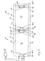
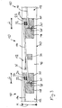
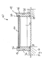
- FIG. 1 to 4 an embodiment of a photovoltaic module device 10 is shown, wherein in Fig.1 and 2 two successively arranged adjacent photovoltaic module devices 10 and in Fig. 3 on average, three photovoltaic module devices 10 arranged one behind the other are shown.
- the photovoltaic module device 10 has a quadrangular frame support structure unit 12, which has two parallel spaced sidewall supports 16, each in its in Fig. 3 right end region over a first transverse edge support 18 and in its in Fig. 3 left end region via a second transverse edge support 20 are interconnected. In the middle between the first transverse edge support 18 and the second transverse edge support 20 is for stabilizing a parallel extending, connected to the side bolsters 16 transverse reinforcement unit 34 is present.
- each side bolster 16 has a rectangular projection unit 22 and in the in Fig. 3 left end portion is a rectangular recess unit 24 formed in the side bolsters 16.
- the geometry of the projection unit 22 and the return unit 24 is so dimensioned that with adjacent successively arranged photovoltaic module devices 10, the projection unit 22, the return unit 24 overlaps and the same cross-sectional height H results, as in the remaining area of the side bolsters 16th
- the second transverse edge support 20 has a smaller cross-sectional height than the first transverse edge support 18.
- Above the first transverse edge support 18 and the second transverse edge support 20 extends continuously through a photovoltaic unit 14, which has an inclination N to the longitudinal direction of the side bolster 16, to the effect that the photovoltaic unit 14 from the second transverse edge support 20 to the first transverse edge support 18 increases.
- the photovoltaic unit 14 in this case extends into the region of the projection unit 22.
- the photovoltaic unit 14 is mounted in a liquid-tight manner in each of its opposite side edges in a groove 26 present on the side wall supports 16 on the inside.
- the frame support unit 12 is mounted with its side bolsters 16 on a not shown substructure 70 of the roof or the facade.
- the photovoltaic unit 14 also extends into the area below the return unit 24, so that adjacent photovoltaic module devices 10, the adjacent photovoltaic units 14 have a supernatant Ü.
- a transversely extending first sealing unit 32 is arranged between the adjacent frame support units 12 or the adjacent overlapping photovoltaic units 14.
- a second sealing unit 33 is provided on the free end side of the side member support 16 below the return unit 24, which seals the gap between adjacent side wall supports 16 in a liquid-tight manner.
- the frame support structure unit 12 can be formed, for example, from a, in particular fiber-reinforced, aluminum foam material. However, it can also be plastic or wood used. Furthermore, 12 aluminum extruded profiles can be used for the frame support structure unit.
- an electronic control unit 40.1, 40.2 is provided below the first transverse edge support 18 and the second transverse edge support 20, which leaves open electronic variation options and, for example, allows parallel / serial switching of the individual photovoltaic units 14 by means of, for example, bus technology for communication with inverters.
- each two first electrical connection units 28 in communication connection which are designed as a socket.
- Opposite is arranged below the second transverse edge support 20 electrical control unit 40.2 with two second electrical connection units 30 in communication connection, which are designed as a plug.
- the first terminal units 28 are automatically contacted with the two terminal units 30, so that an electrically conductive connection between the individual adjacent photovoltaic units 14 is given.
- the electrical control unit 40.1 or 40.2 is designed so that adjacent photovoltaic units 14 can be connected either in parallel or in series.
- control units 40.1, 40.2 are preferably arranged in a recess of the transverse edge support 18 or 20 and closed with a lid or arranged in a separate housing to the transverse edge support 18, 20.
- the electronic control units 40.1, 40.2 further have a connection 42 to which a cable can be connected, which is connected for communication with a central control unit.
- This control unit may for example be an inverter, which is connected via bus technology with other inverters, and is supplied to a central control unit, so that the respective current state of the photovoltaic units 14 can be queried.
- connections for cables may be present, which are connected on the one hand to a central control and evaluation unit and on the other hand allow the connection to the control units 40.1, 40.2. Such connections are not shown in detail in the figures.
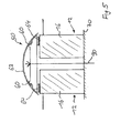
- the side bolsters 16 have a continuous first groove 36 which is mounted on the outside and serves to receive electrical cables for connection to the control units 40.1, 40.2 and supply from the inverter forth. There may be a plurality of first grooves 36, which may also be formed on the inside in the side bolster 16.
- a second groove 38 is provided on the inside in the lower edge area of the side wall support 16, which is suitable for accommodating, for example, the side edge region of a glass plate, so that the insulating properties of the photovoltaic module device 10 are improved.
- the adjacent photovoltaic module devices 10 are shown as they are laid in the direction of fall from left to right of the roof or a facade. In the transverse direction to this fall direction, the photovoltaic module devices 10 are each laid with parallel side bolsters 16, wherein between the side bolsters 16 laterally adjacent photovoltaic module devices 10, a sealing profile is used, which in the FIG. 4 not shown in detail.
- any roof and / or facade surfaces can be designed, with the entire photovoltaic module devices 10 forming a liquid-tight surface as a whole.
- Fig. 6 2 shows a highly schematic representation of how individual photovoltaic module devices 10, which are initially arranged one above the other, form individual strings 44.1,..., 44.4, the respective juxtaposed strings 44.1,..., 44.4 being liquid-tight with each other via profile units 50 are connected and on the other hand connected by the respective profile unit 50 to the corresponding substructure, so that they form a flat, liquid-tight surface.
- the respective strings 44.1,..., 44.4 are electrically communicating in each case connected to an inverter 46 which, depending on the design, passes on its information to a further inverter 46, which then sends the information state of the individual strings 44.1 or photovoltaic units 14 to a central control unit 80 outputs, via which the respective circuit state of the roof or facade surface is controllable.
- the control unit 80 may then drive corresponding photovoltaic units 14 to provide in coordination with the energy supply of the building.
- Fig. 5 2 the region in cross-section is shown, in which two photovoltaic module devices 10 are arranged next to one another, the profile structure 50 being arranged from above in the context of a total structure producing a liquid-tight overall surface, in each case via sealing units 64 on adjacent side wall supports 60 of a photovoltaic system Module device 10 is arranged liquid-tight and is connected via a schematically illustrated screw 90 with the substructure 70.
- the profile unit 50 is in this case designed such that it connects, on the one hand, adjacently arranged frame structural units 12 in a liquid-tight manner, ensures a secure connection to the substructure 70 and, moreover, allows the connection of a wide variety of components through its profile design in the upper-side region.
- the profile unit 50 on connection units 60 which ensures, for example, the connection of an additional removable Abdeckkappenmann 62.
- connection possibilities are given to the connection units 60 of the profile unit 50, which are particularly advantageous in particular for maintenance, repair and installation work.
- the terminal units 60 of the profile unit 50 can at least temporarily be used to provide any ladder rungs possibly necessary repairs, scaffolding, cleaning machines, safety straps during assembly or other connection options to a permanent functionality of the entire roof or facade surface during and after To assure assembly.
- the photovoltaic module device 10 thus makes it possible to create a roof or facade surface without the usual sealing structure must be guaranteed by means of bricks or the like components, and also ensures an optimal, cost-saving installation, at the same time a permanently reliable function is ensured.
Landscapes
- Engineering & Computer Science (AREA)
- Chemical & Material Sciences (AREA)
- Mechanical Engineering (AREA)
- Sustainable Development (AREA)
- Sustainable Energy (AREA)
- Thermal Sciences (AREA)
- Physics & Mathematics (AREA)
- Combustion & Propulsion (AREA)
- Life Sciences & Earth Sciences (AREA)
- General Engineering & Computer Science (AREA)
- Architecture (AREA)
- Civil Engineering (AREA)
- Structural Engineering (AREA)
- Photovoltaic Devices (AREA)
- Roof Covering Using Slabs Or Stiff Sheets (AREA)
Abstract
Description
- Die vorliegende Erfindung betrifft eine Photovoltaik-Moduleinrichtung mit einer Tragstruktur für Photovoltaikeinheiten.
- Es sind Photovoltaik-Moduleinrichtungen in unterschiedlichster Konstruktionsweise bekannt. Bei einer Ausführungsform werden die einzelnen Photovoltaik-Module auf ein Dach montiert und untereinander elektrisch miteinander verbunden. Dies bedeutet einen relativ hohen Montageaufwand und setzt zudem eine dichte Dachfläche voraus.
- Aus der
DE 10 2005 029 465 A1 ist eine Vorrichtung und ein Verfahren zur Wärmeenergieversorgung eines Gebäudes offenbart, das eine aus Solarmodulen bestehende Solaranlage aufweist, die beabstandet zu einer Unterkonstruktion des Gebäudes, zum Beispiel Dach- oder Fassadenkonstruktion, angeordnet ist, die sich dadurch auszeichnet, dass das zwischen der Unterseite der Solaranlage und der Oberseite der Unterkonstruktion vorhandene Luftraumvolumen als geschlossenes Raumvolumen mit zumindest einem Lufteingang und zumindest einem Luftausgang ausgebildet ist, wobei dieses Luftvolumen einer Warmluftverwertungseinrichtung zugeführt wird, die die in dem Raumluftvolumen vorhandene Wärmeenergie umsetzt und für das Gebäude nutzbar macht. - In der
WO 01/75377 A1 WO 94/16170 A1 JP 2000 027395 A - Ausgehend von dem genannten Stand der Technik liegt der vorliegenden Erfindung die Aufgabe beziehungsweise das technische Problem zugrunde, eine Photovoltaik-Moduleinrichtung anzugeben, die in der Lage ist, als gesamte, flüssigkeitsdichte Dach- oder Fassadenfläche ausgebildet zu werden, die einfach montiert werden kann, die eine dauerhaft zuverlässige Funktion gewährleistet und hinsichtlich der jeweils am Bauwerk zu beachtenden Geometrie eine hohe Variabilität gewährleistet, wobei insbesondere das Ziel darin beseht, in konstruktiver einfacher und zuverlässiger Art und Weise die gesamte Dach- oder Fassadenfläche als Photovoltaik-Anlage auszubilden, ohne dass aufwendige zusätzliche Dichtarbeiten an der Dach- oder Fassadenkonstruktion erforderlich sind. Darüber hinaus soll die erfindungsgemäße Photovoltaik-Moduleinrichtung wirtschaftlich herstellbar sein, damit dem jeweiligen Bauherrn eine effektive und kostengünstige Lösung zur elektrischen Energieerzeugung zur Verfügung gestellt werden kann.
- Die erfindungsgemäße Photovoltaik-Moduleinrichtung ist durch die Merkmale des unabhängigen Anspruchs 1 gegeben.
- Vorteilhafte Ausgestaltungen und Weiterbildungen sind Gegenstand der von dem unabhängigen Anspruch 1 direkt oder indirekt abhängigen Ansprüche.
- Die erfindungsgemäße Photovoltaik-Moduleinrichtung zeichnet sich sinngemäß dadurch aus, dass die Tragstruktur eine modulare Rahmentragstruktureinheit aufweist, wobei die Rahmentragstruktureinheit zumindest zwei beabstandete Seitenwangenträger aufweist, an denen eine Photovoltaikeinheit flüssigkeitsdicht eingearbeitet ist, einen ersten Querrandträger und einen beabstandet zum ersten Querrandträger angeordneten zweiten Querrandträger aufweist und die Photovoltaikeinheit mit einem über den ersten Querrandträger hinaus ragenden Überstand vorhanden ist, derart, dass sich die Photovoltaikeinheiten benachbart angeordneter Rahmentragstruktureinheiten überlappenn konnen.
- Dadurch, dass die Moduleinrichtung in einfacher Art und Weise als Rahmentragstruktureinheit ausgebildet ist, können die jeweiligen einzelnen Rahmentragstruktureinheiten problemlos bei der Montage aneinander gefügt werden und insgesamt eine "wasserdichte" Fläche, sei es eine Dach- oder Fassadenfläche, erzeugen. Dadurch, dass zwischen den Photovoltaikeinheiten benachbarter Rahmentragstruktureinheiten einen Überstand besteht, ist eine Eindringen von Flüssigkeiten, insbesondere Regenwasser aufgrund der vertikalen oder geneigten Anordnung der Moduleinrichtungen, von vornherein nicht möglich.
- Durch die einfache Struktur der erfindungsgemäßen Photovoltaik-Moduleinrichtung lässt sich diese wirtschaftlich herstellen, gewährleistet eine einfache Montage und stellt somit dem jeweiligen Bauherrn eine lukrative Möglichkeit dar, die Energieversorgung für ein Gebäude zu sichern. Zudem kann er die durch die erfindungsgemäße Photovoltaik-Moduleinrichtung erzeugte Energie im Falle eines Überschusses in ein Netz einspeisen, was ihm zusätzlich finanzielle Vorteile bringt, da die Energieversorger diese zusätzliche eingespeiste elektrische Energie vergüten müssen.
- Weiterhin können alte Eternit (eingetragene Marke) - Dacheindeckungen durch die erfindungsgemäße Photovoltaik-Moduleinrichtung ersetzt werden, insbesondere ohne dass zusätzliche Dacheindeckungsmaßnahmen nötig sind. Durch die erfindungsgemäße Photovoltaik-Moduleinrichtung ist es möglich, geschlossene Dach- oder Fassadenflächen zu erzeugen, ohne dass zusätzliche Maßnahmen für die Dach- oder Fassadeneindeckung erforderlich sind.
- Eine besonders vorteilhafte Ausgestaltung der erfindungsgemäßen Photovoltaik-Moduleinrichtung zeichnet sich dadurch aus, dass die modulare Rahmentragstruktureinheit als orthogonale Viereckeinheit, insbesondere rechteckige oder quadratische Einheit, ausgebildet ist. Durch die Wahl dieser einfachen Umfangskontur ist eine einfache Handhabung bei der Montage und auch bei der Herstellung gewährleistet. Weitere polygonale Umfangsstrukturen (zum Beispiel Dreieckkonturen) sind problemlos möglich.
- Eine konstruktiv besonders einfache und daher auch bevorzugte Ausgestaltung zeichnet sich dadurch aus, dass die Seitenwangenträger im Bereich oberhalb des ersten Querrandträgers eine Vorsprungeinheit und im Bereich oberhalb des zweiten Querrandträgers eine Rücksprungeinheit aufweisen, derart, dass sich bei angeschlossenen benachbarten Rahmentragstruktureinheiten sich dieselbe Querschnittshöhe des Seitenwangenträgers wie im übrigen Bereich derselben ergibt, das heißt die Vorsprungeinheit im Wesentlichen diesselbe Umfangskontur aufweist wie die Rücksprungeinheit.
- Eine bevorzugte Weiterbildung der erfindungsgemäßen Photovoltaik-Moduleinrichtung zeichnet sich dadurch aus, dass im Bereich des ersten und/oder zweiten Querrandträgers eine Dichteinheit angeordnet ist, die benachbart angeschlossene Rahmentragstruktureinheiten und Photovoltaikeinheiten flüssigkeitsdicht gegeneinander abdichtet.
- Eine hinsichtlich der Flüssigkeitsabdichtung besonders bevorzugte Ausgestaltung zeichnet sich dadurch aus, dass die Photovoltaikeinheit gegenüber der Ebene der Rahmentragstruktureinheit geneigt vorhanden ist, wobei eine in diesem Sinne konstruktiv besonders einfache Weiterbildung sich dadurch auszeichnet, dass die Endrandbereiche der Photovoltaikeinheit oberhalb des ersten Querrandträgers beziehungsweise des zweiten Querrandträgers angeordnet ist, was auch die Stabilität der Moduleinrichtung erhöht.
- Eine besonders vorteilhafte Ausgestaltung zeichnet sich dadurch aus, dass unterhalb der Photovoltaikeinheit Anschlussmöglichkeiten bestehen, um eine Wärmeisolierung anzubringen. Dies kann beispielsweise dadurch umgesetzt werden, dass die Seitenwangenträger innenseitig eine erste Nut aufweisen, in die beispielsweise eine Glasscheibe eingesetzt werden kann. Dadurch erhöht sich der Isolierwert der erfindungsgemäßen Photovoltaik-Moduleinrichtung deutlich.
- Eine konstruktiv besonders vorteilhafte Ausgestaltung, die eine kompakte Verkabelung der einzelnen Photovoltaik-Moduleinrichtungen untereinander gewährleistet, zeichnet sich dadurch aus, dass die Seitenwangenträger innen- und/oder außenseitig Nute aufweisen, in denen problemlos elektrische Kabel verlegt werden können, die zur elektrischen Kommunikation benachbarter Photovoltaik-Moduleinrichtungen dienen und im Ergebnis einer zentralen Steuereinheit zugeführt werden, die die jeweils aktuelle Energiesituation analysiert, auswertet und nutzt.
- Eine konstruktiv besonders einfache, eine wirtschaftliche Herstellung und eine dauerhaft zuverlässige Funktion gewährleistende vorteilhafte Ausgestaltung zeichnet sich dadurch aus, dass die Photovoltaikeinheit innerhalb einer Nut der Seitenwangenträger flüssigkeitsdicht angeordnet ist.
- Als Material für die Rahmentragstruktureinheit wird bevorzugt Kunststoff, Aluminium oder Aluminiumschaum, insbesondere mit Faserverstärkung, eingesetzt.
- Es ist auch in vorteilhafter Art und Weise möglich, für die Rahmenstruktureinheit Holz oder Holzwerkstoff, insbesondere beschichteten Holwerkstoff einzusetzen, wobei in vorteilhafter Art und Weise hinsichtlich einer wirtschaftlichen Herstellung die Beschichtung lediglich oberseitig angebracht ist.
- Um die Stabilität der Rahmenkonstruktion zu erhöhen, ist in einer vorteilhaften Weiterbildung im Bereich zwischen dem ersten Querrandträger und dem zweiten Querrandträger von Seitenwangenträger zur Seitenwangenträger verlaufend eine Querverstärkungseinheit eingezogen.
- Um einen einfachen elektrischen Anschluss benachbarter Photovoltaik-Moduleinrichtungen zu gewährleisten, zeichnet sich eine vorteilhafte Ausgestaltung dadurch aus, dass eine Buchsen-Steck-Verbindung vorhanden ist, die automatisch beim Aneinanderfügen benachbarter Rahmentragstruktureinheiten eine elektrisch leitende Verbindung herstellt.
- Bevorzugt ist an der Rahmentragstruktureinheit eine elektrische Steuereinheit, insbesondere Platine, vorhanden, mittels derer die elektrische beziehungsweise elektronische Kommunikation benachbarter Photovoltaikeinheiten einstellbar beziehungsweise steuerbar ist.
- Die elektrische Steuereinrichtung ist hierbei unter anderem in der Lage, wahlweise den Zustand paralleler oder serieller Schaltung benachbarter Photovoltaikeinheiten vorzunehmen.
- Um zu einer während der Montage einfach handhabbaren Einheit zu gelangen, zeichnet sich eine bevorzugte Weiterbildung dadurch aus, dass die Länge der Photovoltaik-Moduleinrichtungen im Bereich zwischen 1 m bis 3 m (Meter), insbesondere im Bereich zwischen 1,6 m bis 2,0 m (Meter), liegt.
- Des Weiteren besitzt jede Rahmentragstruktureinheit elektrische Anschlüsse, mittels derer eine elektrische beziehungsweise elektronische Kommunikation mit einer zentralen Steuer- und Auswerteinheit möglich ist.
- Weitere Ausführungsformen und Vorteile der Erfindung ergeben sich durch die in den Ansprüchen ferner aufgeführten Merkmale sowie durch das nachstehend angegebene Ausführungsbeispiel. Die Merkmale der Ansprüche können in beliebiger Weise miteinander kombiniert werden, insoweit sie sich nicht offensichtlich gegenseitig ausschließen.
- Die Erfindung sowie vorteilhafte Ausführungsformen und Weiterbildungen derselben werden im Folgenden anhand der in der Zeichnung dargestellten Beispiele näher beschrieben und erläutert. Die der Beschreibung und der Zeichnung zu entnehmenden Merkmale können einzeln für sich oder zu mehreren in beliebiger Kombination erfindungsgemäß angewandt werden. Es zeigen:
- Fig. 1
- schematische Draufsicht auf den Ausschnitt einer Dachfläche mit zwei benachbart angeordneten Photovoltaik-Moduleinrichtungen mit jeweils einer rechteckförmigen Rahmentragstruktureinheit,
- Fig. 2
- schematische Unteransicht auf die Dachfläche gemäß
Fig. 1 , - Fig. 3
- schematischer Längsschnitt durch benachbart angeordnete Photovoltaik-Moduleinrichtungen,
- Fig. 4
- schematischer Querschnitt durch eine Photovoltaik-Moduleinrichtung gemäß
Fig. 3 , - Fig. 5
- schematischer Detailquerschnitt durch die Seitenwangen einer erfindungsgemäßen Photovoltaik-Moduleinrichtung mit angeschlossener Profileinheit, die sowohl die Abdichtung benachbarter Moduleinrichtungen gewährleistet, einen Anschluss an die Unterkonstruktion ermöglicht und darüber hinaus Anschlussmöglichkeiten für weitere Bauteile zur Verfügung stellt, und
- Fig. 6
- stark schematisierte Darstellung der Zusammenfassung mehrerer übereinander und nebeneinander angeordneter Photovoltaik-Moduleinrichtungen, die eine geschlossene Dach- oder Fassadenfläche bilden und elektrisch beziehungsweise elektronisch kommunizierend miteinander ausgebildet sind.
- In den
Fig. 1 bis 4 ist ein Ausführungsbeispiel einer Photovoltaik-Moduleinrichtung 10 dargestellt, wobei inFig.1 und2 zwei hintereinander benachbart angeordnete Photovoltaik-Moduleinrichtungen 10 und inFig. 3 im Schnitt drei benachbart hintereinander angeordnete Photovoltaik-Moduleinrichtungen 10 dargestellt sind. - Die Photovoltaik-Moduleinrichtung 10 weist eine viereckförmige Rahmentragstruktureinheit 12 auf, die zwei parallel beabstandete Seitenwangenträger 16 besitzt, die jeweils in ihrem in
Fig. 3 rechten Endbereich über einen ersten Querrandträger 18 und in ihrem inFig. 3 linken Endbereich über einen zweiten Querrandträger 20 miteinander verbunden sind. In der Mitte zwischen dem ersten Querrandträger 18 und dem zweiten Querrandträger 20 ist zur Stabilisierung eine parallel verlaufende, an den Seitenwangenträgern 16 angeschlossene Querverstärkungseinheit 34 vorhanden. - Die Seitenwangenträger 16 weisen eine Höhe H auf. Im in
Fig. 3 rechten Endbereich weist jeder Seitenwangenträger 16 eine rechteckförmige Vorsprungeinheit 22 auf und in dem inFig. 3 linken Endbereich ist eine rechteckförmige Rücksprungeinheit 24 in die Seitenwangenträger 16 eingeformt. Die Geometrie der Vorsprungeinheit 22 und der Rücksprungeinheit 24 ist dabei so bemessen, dass bei benachbart hintereinander angeordneten Photovoltaik-Moduleinrichtungen 10 die Vorsprungeinheit 22 die Rücksprungeinheit 24 überlappt und sich dieselbe Querschnittshöhe H ergibt, wie im übrigen Bereich der Seitenwangenträger 16. - Der zweite Querrandträger 20 weist eine geringere Querschnittshöhe als der erste Querrandträger 18 auf. Oberhalb des ersten Querrandträgers 18 und dem zweiten Querrandträger 20 verläuft durchgehend eine Photovoltaikeinheit 14, die zur Längsrichtung des Seitenwangenträgers 16 eine Neigung N aufweist, dahingehend, dass die Photovoltaikeinheit 14 vom zweiten Querrandträger 20 zum ersten Querrandträger 18 ansteigend verläuft. Die Photovoltaikeinheit 14 verläuft hierbei bis in den Bereich der Vorsprungeinheit 22 hinein.
- Die Photovoltaikeinheit 14 ist in ihren gegenüberliegenden Seitenrändern jeweils in einer innenseitig an den Seitenwangenträgern 16 vorhandenen Nut 26 flüssigkeitsdicht gelagert.
- Die Rahmentragstruktureinheit 12 ist mit ihren Seitenwangenträgern 16 auf einer nicht näher dargestellten Unterkonstruktion 70 des Daches oder der Fassade gelagert.
- Die Photovoltaikeinheit 14 verläuft auch bis in den Bereich unterhalb der Rücksprungeinheit 24, so dass bei benachbart angeordneten Photovoltaik-Moduleinrichtungen 10 die benachbarten Photovoltaikeinheiten 14 einen Überstand Ü aufweisen. In diesem Überstandsbereich Ü ist zwischen den benachbarten Rahmentragstruktureinheiten 12 beziehungsweise den benachbart überlappenden Photovoltaikeinheiten 14 eine in Querrichtung verlaufende erste Dichteinheit 32 angeordnet. Des Weiteren ist an der freien Stirnseite der Seitenwangenträger 16 unterhalb der Rücksprungeinheit 24 eine zweite Dichteinheit 33 vorhanden, die den Spalt zwischen benachbarten Seitenwangenträgern 16 flüssigkeitsdicht abdichtet.
- Die Rahmentragstruktureinheit 12 kann beispielsweise aus einem, insbesondere faserverstärkten, Aluminiumschaummaterial gebildet sein. Es kann jedoch auch Kunststoff oder Holz zum Einsatz kommen. Des Weiteren können für die Rahmentragstruktureinheit 12 Aluminiumstrangpressprofile verwendet werden.
- Unterhalb des ersten Querrandträgers 18 und des zweiten Querrandträgers 20 ist jeweils eine elektronische Steuereinheit 40.1, 40.2 vorhanden, die elektronische Variationsmöglichkeiten offen lässt und beispielsweise eine Umschaltung parallel/seriell der einzelnen Photovoltaikeinheiten 14 mittels beispielsweise Bustechnologie zur Kommunikation mit Wechselrichtern ermöglicht.
- Mit der unterhalb dem ersten Querrandträger 18 vorhandenen elektrischen Steuereinheit 40.1 stehen jeweils zwei erste elektrische Anschlusseinheiten 28 in Kommunikationsverbindung, die als Buchse ausgebildet sind. Gegenüberliegend steht die unterhalb des zweiten Querrandträgers 20 angeordnete elektrische Steuereinheit 40.2 mit zwei zweiten elektrischen Anschlusseinheiten 30 in Kommunikationsverbindung, die als Stecker ausgebildet sind. Bei der Montage benachbarter Photovoltaik-Moduleinrichtungen 10 werden die ersten Anschlusseinheiten 28 automatisch mit den beiden Anschlusseinheiten 30 kontaktiert, so dass eine elektrisch leitende Verbindung zwischen den einzelnen benachbarten Photovoltaikeinheiten 14 gegeben ist.
- Die elektrische Steuereinheit 40.1 beziehungsweise 40.2 ist dabei so ausgebildet, dass benachbarte Photovoltaikeinheiten 14 entweder parallel oder in Serie geschaltet werden können.
- Die Steuereinheiten 40.1, 40.2 sind bevorzugt in einer Ausnehmung der Querrandträger 18 beziehungsweise 20 angeordnet und mit einem Deckel verschlossen oder in einem separaten Gehäuse an die Querrandträger 18, 20 angeordnet.
- Die elektronischen Steuereinheiten 40.1, 40.2 besitzen weiterhin einen Anschluss 42, an das ein Kabel anschließbar ist, das zur Kommunikation mit einer zentralen Steuereinheit verbunden ist.
- Diese Steuereinheit kann beispielsweise ein Wechselrichter sein, der über Bustechnologie mit weiteren Wechselrichtern verbunden ist, und einer zentralen Steuereinheit zugeführt wird, damit der jeweilige aktuelle Zustand der Photovoltaikeinheiten 14 abgefragt werden kann.
- Zusätzlich können an den Querrandträgern 18, 20 Anschlüsse für Kabel vorhanden sein, die einerseits an eine zentrale Steuer- und Auswerteinheit angeschlossen sind und andererseits den Anschluss zu den Steuereinheiten 40.1, 40.2 ermöglichen. Derartige Anschlüsse sind in den Figuren nicht näher dargestellt.
- Wie in
Fig. 4 dargestellt weisen die Seitenwangenträger 16 eine durchgehende erste Nut 36, die außenseitig angebracht ist und dazu dient, elektrische Kabel zum Anschluss an die Steuereinheiten 40.1, 40.2 aufzunehmen und vom Wechselrichter her zuzuführen. Es können mehrere erste Nute 36 vorhanden sein, die auch innenseitig in den Seitenwangenträger 16 eingeformt sein können. - Schließlich ist noch im unteren Randbereich der Seitenwangenträger 16 innenseitig eine zweite Nut 38 vorhanden, die dazu geeignet ist, beispielsweise den Seitenrandbereich einer Glasplatte aufzunehmen, so dass die Isoliereigenschaften der Photovoltaik-Moduleinrichtung 10 verbessert werden.
- In den Figuren sind die benachbarten Photovoltaik-Moduleinrichtungen 10 so dargestellt, wie sie in Fallrichtung von links nach rechts des Daches beziehungsweise einer Fassade verlegt werden. In Querrichtung zu dieser Fallrichtung werden die Photovoltaik-Moduleinrichtungen 10 jeweils mit parallel angeordneten Seitenwangenträgern 16 verlegt, wobei zwischen den Seitenwangenträgern 16 seitlich benachbarter Photovoltaik-Moduleinrichtungen 10 ein Dichtprofil eingesetzt wird, was in der
Figur 4 nicht näher dargestellt ist. Dadurch lassen sich beliebige Dach- und/oder Fassadenflächen gestalten, wobei die gesamten Photovoltaik-Moduleinrichtungen 10 insgesamt eine flüssigkeitsdichte Fläche bilden. - In
Fig. 6 ist stark schematisiert dargestellt, wie einzelne Photovoltaik-Moduleinrichtungen 10, die zunächst übereinander angeordnet sind, einzelne Strings 44.1, ...., 44.4 bilden, wobei die jeweiligen nebeneinander angeordnete Strings 44.1, ...., 44.4 über Profileinheiten 50 einerseits flüssigkeitsdicht miteinander verbunden sind und andererseits durch die jeweilige Profileinheit 50 an die entsprechende Unterkonstruktion angeschlossen sind, so dass sie eine ebene, flüssigkeitsdichte Fläche bilden. Die jeweiligen Strings 44.1, ...., 44.4 sind elektrisch kommunizierend jeweils mit einem Wechselrichter 46 verbunden, der je nach Ausgestaltung seine Information weitergibt an einen weiteren Wechselrichter 46, der dann den Informationszustand der einzelnen Strings 44.1 beziehungsweise Photovoltaikeinheiten 14 an eine zentrale Steuereinheit 80 abgibt, über die der jeweilige Schaltungszustand der Dach- beziehungsweise Fassadenfläche steuerbar ist. Umgekehrt kann die Steuereinheit 80 dann entsprechende Photovoltiakeinheiten 14 ansteuern, um in Abstimmung mit der Energieversorgung des Gebäudes Vorkehrungen zu treffen. - In
Fig. 5 ist stark schematisiert der Bereich im Querschnitt dargestellt, in dem zwei Photovoltaik-Moduleinrichtungen 10 nebeneinander angeordnet sind, wobei die von oben her im Rahmen einer eine flüssigkeitsdichten Gesamtfläche erzeugende Gesamtstruktur eine Profileinheit 50 angeordnet ist, die jeweils über Dichteinheiten 64 auf benachbarten Seitenwangenträgern 60 einer Photovoltaik-Moduleinrichtung 10 flüssigkeitsdicht angeordnet ist und über eine schematisch dargestellte Schraubverbindung 90 mit der Unterkonstruktion 70 verbunden ist. - Die Profileinheit 50 ist hierbei so ausgestaltet, dass sie einerseits benachbart angeordnete Rahmenstruktureinheiten 12 flüssigkeitsdicht verbindet, eine sichere Anbindung an die Unterkonstruktion 70 gewährleistet und darüber hinaus durch ihre Profilausgestaltung im oberseitigen Bereich den Anschluss unterschiedlichster Bauteile ermöglicht. Hierzu weist die Profileinheit 50 Anschlusseinheiten 60 auf, die beispielsweise den Anschluss einer zusätzlichen lösbaren Abdeckkappenleiste 62 gewährleistet.
- An die Anschlusseinheiten 60 der Profileinheit 50 sind darüber hinaus Anschlussmöglichkeiten gegeben, die insbesondere bei Wartungs-, Reparatur- und Montagearbeiten besonders vorteilhaft sind. So können die Anschlusseinheiten 60 der Profileinheit 50 zumindest temporär dazu genutzt werden, um eventuelle Leitersprossen bei möglicherweise erforderlichen Reparaturen, Gerüste, Reinigungsmaschinen, Sicherungsgurte während der Montage oder sonstige Anschlussmöglichkeiten zu bieten, um eine dauerhafte Funktionalität der gesamten Dach- oder Fassadenfläche während und nach deren Montage zu gewährleisten.
- Die erfindungsgemäße Photovoltaik-Moduleinrichtung 10 ermöglicht somit eine Erstellung einer Dach- oder Fassadenfläche ohne dass die übliche Dichtstruktur mittels Ziegeln oder dergleichen Bauteile gewährleistet werden muss, und gewährleistet darüber hinaus eine optimale, kostensparende Montage, wobei gleichzeitig eine dauerhaft zuverlässige Funktion gewährleistet ist.
Claims (15)
- Photovoltaik-Moduleinrichtung (10) mit einer Tragstruktur für Photovoltaikeinheiten (14), wobei- die Tragstruktur eine modulare Rahmentragstruktureinheit (12) aufweist, wobei- die Rahmentragstruktureinheit (12)-- zumindest zwei beabstandete Seitenwangenträger (16) aufweist, an denen eine Photovoltaikeinheit (14) flüssigkeitsdicht eingearbeitet ist,-- einen ersten Querrandträger (18) und einen beabstandet zum ersten Querrandträger (18) angeordneten zweiten Querrandträger (20) aufweist, dadurch gekennzeichnet, dass-- die Photovoltaikeinheit (14) mit einem über den ersten Querrandträger (18) hinaus ragenden Überstand (Ü) vorhanden ist, derart, dass sich die Photovoltaikeinheiten (14) benachbart angeordneter Rahmentragstruktureinheiten (12) überlappen können.
- Photovoltaik-Moduleinrichtung nach Anspruch 1,- dadurch gekennzeichnet, dass- die Rahmentragstruktureinheit (12) als orthogonale Viereckstruktureinheit, insbesondere als Rechteck- oder Quadrateinheit, oder als Dreieckstruktur, ausgebildet ist.
- Photovoltaik-Moduleinrichtung nach Anspruch 1 oder 2,- dadurch gekennzeichnet, dass- die Seitenwangenträger (16) im Bereich oberhalb des ersten Querrandträgers (18) eine Vorsprungeinheit (22) und im Bereich oberhalb des zweiten Querrandträgers (20) eine Rücksprungeinheit (24) aufweisen, derart, dass sich bei angeschlossenen benachbarten Rahmentragstruktureinheiten (12) sich dieselbe Querschnittshöhe (H) des Seitenwangenträgers (16) wie im übrigen Bereich derselben ergibt, das heißt die Vorsprungeinheit (22) im Wesentlichen dieselbe Umfangskontur aufweist wie die Rücksprungeinheit (24).
- Photovoltaik-Moduleinrichtung nach einem oder mehreren der vorstehenden Ansprüche,- dadurch gekennzeichnet, dass- im Bereich des ersten und/oder zweiten Querrandträgers (18, 20) eine Dichteintheit (32) angeordnet ist, die benachbart angeschlossene Rahmentragstruktureinheiten (12) und Photovoltaikeinheiten (14) flüssigkeitsdicht gegeneinander abdichtet.
- Photovoltaik-Moduleinrichtung nach einem oder mehreren der vorstehenden Ansprüche,- dadurch gekennzeichnet, dass- die Photovoltaikeinheit (14) gegenüber der Ebene der Rahmentragstruktureinheit (12) geneigt vorhanden ist.
- Photovoltaik-Moduleinrichtung nach Anspruch 5,- dadurch gekennzeichnet, dass- die Endrandbereiche der Photovoltaikeinheit (14) oberhalb des ersten Querrandträgers (18) und des zweiten Querrandträgers (20) angeordnet sind.
- Photovoltaik-Moduleinrichtung nach einem oder mehreren der vorstehenden Ansprüche,- dadurch gekennzeichnet, dass- die Photovoltaikeinheit (14) innerhalb einer Nut (26) der Seitenwangenträger (16) flüssigkeitsdicht angeordnet ist.
- Photovoltaik-Moduleinrichtung nach einem oder mehreren der vorstehenden Ansprüche,- dadurch gekennzeichnet, dass- unterhalb der Photovoltaikeinheit (14) isolierendes Material angeordnet ist.
- Photovoltaik-Moduleinrichtung nach einem oder mehreren der vorstehenden Ansprüche,- dadurch gekennzeichnet, dass- die Seitenwangenträger (16) innenseitig eine Anschlusseinrichtung, insbesondere erste Nut (38), zum Anschluss von isolierendem Material, insbesondere einer Glasscheibe oder zum Anschluss einer Heizeinheit als Zusatzfunktion, aufweisen.
- Photovoltaik-Moduleinrichtung nach einem oder mehreren der vorstehenden Ansprüche,- dadurch gekennzeichnet dass- außen- und/oder innenseitig der Seitenwangenträger (16) eine Anschlusseinrichtung, insbesondere zweite Nut (36), für Kabeleinheiten vorhanden ist.
- Photovoltaik-Moduleinrichtung nach einem oder mehreren der vorstehenden Ansprüche,- dadurch gekennzeichnet, dass- die Rahmentragstruktureinheit (12) als Holz oder Holzwerkstoffbauteil oder als Kunststoffbauteil, insbesondere gespritztes oder tiefgezogenes Kunststoffbauteil, insbesondere mit Faserverstärkung oder als Aluminiumstrangpressprofil oder als Aluminiumschaumkonstruktion, insbesondere als faserverstärkte Aluminiumschamnkonstruktion, ausgebildet ist.
- Photovoltaik-Moduleinrichtung nach einem oder mehreren der vorstehenden Ansprüche,- dadurch gekennzeichnet, dass- zwischen dem ersten Querrandträger (18) und dem zweiten Querrandträger (20) zusätzlich eine Querverstärkungseinheit (34) vorhanden ist.
- Photovoltaik-Moduleinrichtung nach einem oder mehreren der vorstehenden Ansprüche,- dadurch gekennzeichnet, dass- die Photovoltaikeinheiten (14) benachbarter Rahmentragstruktureinheiten (12) über eine Buchsen-Steck-Verbindung elektrisch miteinander verbunden sind.
- Photovoltaik-Moduleinrichtung nach einem oder mehreren der vorstehenden Ansprüche,- dadurch gekennzeichnet, dass- die Rahmentragstruktureinheit (12) eine elektrische Steuereinheit (40) besitzt, mittels derer die elektrische beziehungsweise elektronische Kommunikation benachbarter Photovoltaikeinheiten (14) einstellbar beziehungsweise steuerbar ist.
- Photovoltaik-Moduleinrichtung nach einem oder mehreren der vorstehenden Ansprüche,- dadurch gekennzeichnet, dass- jede modulare Rahmentragstruktureinheit (12) elektrische Anschlüsse besitzt, mittels derer eine elektrische beziehungsweise elektronische Kommunikation mit einer zentralen Steuer- und Auswerteinheit ermöglicht wird.
Priority Applications (1)
| Application Number | Priority Date | Filing Date | Title |
|---|---|---|---|
| PL08860405T PL2240728T3 (pl) | 2007-12-10 | 2008-12-08 | Fotowoltaiczne urządzenie modułowe |
Applications Claiming Priority (2)
| Application Number | Priority Date | Filing Date | Title |
|---|---|---|---|
| DE200710059650 DE102007059650A1 (de) | 2007-12-10 | 2007-12-10 | Photovoltaik-Moduleinrichtung |
| PCT/DE2008/002019 WO2009074135A2 (de) | 2007-12-10 | 2008-12-08 | Photovoltaik-moduleinrichtung |
Publications (2)
| Publication Number | Publication Date |
|---|---|
| EP2240728A2 EP2240728A2 (de) | 2010-10-20 |
| EP2240728B1 true EP2240728B1 (de) | 2012-06-20 |
Family
ID=40679832
Family Applications (1)
| Application Number | Title | Priority Date | Filing Date |
|---|---|---|---|
| EP20080860405 Not-in-force EP2240728B1 (de) | 2007-12-10 | 2008-12-08 | Photovoltaik-moduleinrichtung |
Country Status (5)
| Country | Link |
|---|---|
| EP (1) | EP2240728B1 (de) |
| DE (1) | DE102007059650A1 (de) |
| ES (1) | ES2389880T3 (de) |
| PL (1) | PL2240728T3 (de) |
| WO (1) | WO2009074135A2 (de) |
Families Citing this family (5)
| Publication number | Priority date | Publication date | Assignee | Title |
|---|---|---|---|---|
| EP2804224A1 (de) | 2013-05-13 | 2014-11-19 | Fraunhofer Gesellschaft zur Förderung der angewandten Forschung e.V. | Verfahren zur Herstellung eines Photovoltaikmoduls |
| SE539480C2 (en) * | 2014-10-09 | 2017-10-03 | Solibro Res Ab | System and method of mounting a solar panel; and an elongated solar panel mounting bar |
| US10673373B2 (en) | 2016-02-12 | 2020-06-02 | Solarcity Corporation | Building integrated photovoltaic roofing assemblies and associated systems and methods |
| CN107100306B (zh) * | 2017-05-29 | 2021-10-22 | 海南泰捷建设工程有限公司 | 一种绿色建筑幕墙结构 |
| JP7278460B1 (ja) | 2022-05-23 | 2023-05-19 | 東京瓦斯株式会社 | 太陽光パネル設置構造 |
Family Cites Families (11)
| Publication number | Priority date | Publication date | Assignee | Title |
|---|---|---|---|---|
| US4936063A (en) * | 1989-05-19 | 1990-06-26 | Humphrey John B | Frame flanges for mounting photovoltaic modules direct to roof structural framing |
| DE4140682C2 (de) * | 1991-12-10 | 1995-01-12 | Flachglas Solartechnik Gmbh | Solarmodul in Plattenform, insbesondere zur Verwendung als Fassaden- oder Dachelement |
| WO1994016170A1 (fr) * | 1993-01-12 | 1994-07-21 | Misawa Homes Co., Ltd. | Toit equipe de piles solaires |
| GB2301849B (en) * | 1995-06-06 | 1998-12-23 | Barrie Peter Moore | Roofing system |
| US5746839A (en) * | 1996-04-08 | 1998-05-05 | Powerlight Corporation | Lightweight, self-ballasting photovoltaic roofing assembly |
| DE29616015U1 (de) * | 1996-09-16 | 1997-12-11 | Titze, Michael, Dipl.-Ing. (FH), 25335 Elmshorn | Solar-Dachstein |
| JP2000027395A (ja) * | 1998-07-15 | 2000-01-25 | Fujisash Co | 太陽電池パネル及びその取付構造 |
| DE19921044A1 (de) * | 1999-05-07 | 2000-12-07 | Dachziegelwerke Pfleiderer Gmb | Solardachmodul |
| AUPQ668200A0 (en) * | 2000-04-04 | 2000-05-04 | Erling, Peter S | Framing systems for solar panels |
| JP2006132111A (ja) * | 2004-11-02 | 2006-05-25 | Sekisui Chem Co Ltd | 太陽電池パネルの支持具及び太陽電池パネルの支持構造 |
| DE102005029465A1 (de) | 2005-06-24 | 2006-12-28 | Thomas Habel | Vorrichtung und Verfahren zur Wärmeenergieversorgung eines Gebäudes |
-
2007
- 2007-12-10 DE DE200710059650 patent/DE102007059650A1/de not_active Withdrawn
-
2008
- 2008-12-08 ES ES08860405T patent/ES2389880T3/es active Active
- 2008-12-08 WO PCT/DE2008/002019 patent/WO2009074135A2/de not_active Ceased
- 2008-12-08 PL PL08860405T patent/PL2240728T3/pl unknown
- 2008-12-08 EP EP20080860405 patent/EP2240728B1/de not_active Not-in-force
Also Published As
| Publication number | Publication date |
|---|---|
| ES2389880T3 (es) | 2012-11-02 |
| PL2240728T3 (pl) | 2012-11-30 |
| DE102007059650A1 (de) | 2009-06-18 |
| WO2009074135A2 (de) | 2009-06-18 |
| EP2240728A2 (de) | 2010-10-20 |
| WO2009074135A3 (de) | 2010-06-24 |
Similar Documents
| Publication | Publication Date | Title |
|---|---|---|
| CH684202A5 (de) | Dacheindeckung und Bauelement mit Solarzellen. | |
| DE4140682C2 (de) | Solarmodul in Plattenform, insbesondere zur Verwendung als Fassaden- oder Dachelement | |
| DE102007056600A1 (de) | Photovoltaikanlage mit einer Matrix aus rahmenlosen Solarmodulen | |
| EP2187447A2 (de) | Montagevorrichtung für Solarmodule mit einem großen Aspektverhältnis. | |
| EP2240728B1 (de) | Photovoltaik-moduleinrichtung | |
| DE102013006332A1 (de) | Solarmodulträger für die Belegung von schrägen Objektflächen mit homogener Flächenbedeckung | |
| EP3245457B1 (de) | Solardachplattensystem | |
| EP2584282A1 (de) | Profilelement für eine Indach-Solarsystemanordnung | |
| WO2012031581A1 (de) | Solares umkehrdach | |
| DE102009055948A1 (de) | Profilelement eines Daches und Anordnung von Profilelementen | |
| EP3761503B1 (de) | Bauelemente mit photovoltaik | |
| DE102004057042A1 (de) | Wandverkleidungsplatte für eine Gebäudeaußenwand mit einem Solargenerator | |
| WO2010017982A2 (de) | Solarmodul für eine solaranlage, insbesondere photovoltaik-anlage | |
| EP2385326A2 (de) | Montagesatz für Solarmodule auf einer ebenen Fläche | |
| DE202012008622U1 (de) | Befestigungssystem für eine Indach-Solarsystemanordnung | |
| DE202006009884U1 (de) | Unterkonstruktion für PV-Anlage | |
| WO2011054943A1 (de) | Solarmodul mit schwenkbarer stützwand | |
| WO2019048007A1 (de) | Solarmodul und solarmodul-system | |
| DE202011105402U1 (de) | Unterkonstruktion für Solarmodule von Photovoltaik-Anlagen | |
| EP1818625B1 (de) | Solarkollektoranordnung | |
| DE202011101835U1 (de) | Photovoltaikanlage | |
| DE102023115997A1 (de) | Quaderförmiges Schutzgehäuse, insbesondere quaderförmiges Anlagen- und/oder Instrumentenschutzhaus | |
| CH719895B1 (de) | Fassadenelement mit Photovoltaikmodul. | |
| DE3231798A1 (de) | Verfahren zur herstellung eines solargenerators fuer solartechnische grossanlagen | |
| DE102024105622A1 (de) | Photovoltaikmodulanordnung mit Photovoltaikmodulen |
Legal Events
| Date | Code | Title | Description |
|---|---|---|---|
| PUAI | Public reference made under article 153(3) epc to a published international application that has entered the european phase |
Free format text: ORIGINAL CODE: 0009012 |
|
| 17P | Request for examination filed |
Effective date: 20100709 |
|
| AK | Designated contracting states |
Kind code of ref document: A2 Designated state(s): AT BE BG CH CY CZ DE DK EE ES FI FR GB GR HR HU IE IS IT LI LT LU LV MC MT NL NO PL PT RO SE SI SK TR |
|
| DAX | Request for extension of the european patent (deleted) | ||
| GRAP | Despatch of communication of intention to grant a patent |
Free format text: ORIGINAL CODE: EPIDOSNIGR1 |
|
| GRAS | Grant fee paid |
Free format text: ORIGINAL CODE: EPIDOSNIGR3 |
|
| GRAA | (expected) grant |
Free format text: ORIGINAL CODE: 0009210 |
|
| AK | Designated contracting states |
Kind code of ref document: B1 Designated state(s): AT BE BG CH CY CZ DE DK EE ES FI FR GB GR HR HU IE IS IT LI LT LU LV MC MT NL NO PL PT RO SE SI SK TR |
|
| REG | Reference to a national code |
Ref country code: GB Ref legal event code: FG4D Free format text: NOT ENGLISH |
|
| REG | Reference to a national code |
Ref country code: CH Ref legal event code: EP |
|
| REG | Reference to a national code |
Ref country code: AT Ref legal event code: REF Ref document number: 563287 Country of ref document: AT Kind code of ref document: T Effective date: 20120715 |
|
| REG | Reference to a national code |
Ref country code: IE Ref legal event code: FG4D Free format text: LANGUAGE OF EP DOCUMENT: GERMAN |
|
| REG | Reference to a national code |
Ref country code: DE Ref legal event code: R096 Ref document number: 502008007524 Country of ref document: DE Effective date: 20120823 |
|
| REG | Reference to a national code |
Ref country code: CH Ref legal event code: NV Representative=s name: ISLER & PEDRAZZINI AG |
|
| PG25 | Lapsed in a contracting state [announced via postgrant information from national office to epo] |
Ref country code: FI Free format text: LAPSE BECAUSE OF FAILURE TO SUBMIT A TRANSLATION OF THE DESCRIPTION OR TO PAY THE FEE WITHIN THE PRESCRIBED TIME-LIMIT Effective date: 20120620 Ref country code: SE Free format text: LAPSE BECAUSE OF FAILURE TO SUBMIT A TRANSLATION OF THE DESCRIPTION OR TO PAY THE FEE WITHIN THE PRESCRIBED TIME-LIMIT Effective date: 20120620 Ref country code: NO Free format text: LAPSE BECAUSE OF FAILURE TO SUBMIT A TRANSLATION OF THE DESCRIPTION OR TO PAY THE FEE WITHIN THE PRESCRIBED TIME-LIMIT Effective date: 20120920 Ref country code: LT Free format text: LAPSE BECAUSE OF FAILURE TO SUBMIT A TRANSLATION OF THE DESCRIPTION OR TO PAY THE FEE WITHIN THE PRESCRIBED TIME-LIMIT Effective date: 20120620 |
|
| REG | Reference to a national code |
Ref country code: ES Ref legal event code: FG2A Ref document number: 2389880 Country of ref document: ES Kind code of ref document: T3 Effective date: 20121102 |
|
| REG | Reference to a national code |
Ref country code: NL Ref legal event code: VDEP Effective date: 20120620 |
|
| REG | Reference to a national code |
Ref country code: LT Ref legal event code: MG4D Effective date: 20120620 |
|
| PG25 | Lapsed in a contracting state [announced via postgrant information from national office to epo] |
Ref country code: GR Free format text: LAPSE BECAUSE OF FAILURE TO SUBMIT A TRANSLATION OF THE DESCRIPTION OR TO PAY THE FEE WITHIN THE PRESCRIBED TIME-LIMIT Effective date: 20120921 Ref country code: SI Free format text: LAPSE BECAUSE OF FAILURE TO SUBMIT A TRANSLATION OF THE DESCRIPTION OR TO PAY THE FEE WITHIN THE PRESCRIBED TIME-LIMIT Effective date: 20120620 Ref country code: HR Free format text: LAPSE BECAUSE OF FAILURE TO SUBMIT A TRANSLATION OF THE DESCRIPTION OR TO PAY THE FEE WITHIN THE PRESCRIBED TIME-LIMIT Effective date: 20120620 Ref country code: LV Free format text: LAPSE BECAUSE OF FAILURE TO SUBMIT A TRANSLATION OF THE DESCRIPTION OR TO PAY THE FEE WITHIN THE PRESCRIBED TIME-LIMIT Effective date: 20120620 |
|
| REG | Reference to a national code |
Ref country code: PL Ref legal event code: T3 |
|
| PG25 | Lapsed in a contracting state [announced via postgrant information from national office to epo] |
Ref country code: CZ Free format text: LAPSE BECAUSE OF FAILURE TO SUBMIT A TRANSLATION OF THE DESCRIPTION OR TO PAY THE FEE WITHIN THE PRESCRIBED TIME-LIMIT Effective date: 20120620 Ref country code: CY Free format text: LAPSE BECAUSE OF FAILURE TO SUBMIT A TRANSLATION OF THE DESCRIPTION OR TO PAY THE FEE WITHIN THE PRESCRIBED TIME-LIMIT Effective date: 20120620 Ref country code: IS Free format text: LAPSE BECAUSE OF FAILURE TO SUBMIT A TRANSLATION OF THE DESCRIPTION OR TO PAY THE FEE WITHIN THE PRESCRIBED TIME-LIMIT Effective date: 20121020 Ref country code: RO Free format text: LAPSE BECAUSE OF FAILURE TO SUBMIT A TRANSLATION OF THE DESCRIPTION OR TO PAY THE FEE WITHIN THE PRESCRIBED TIME-LIMIT Effective date: 20120620 Ref country code: EE Free format text: LAPSE BECAUSE OF FAILURE TO SUBMIT A TRANSLATION OF THE DESCRIPTION OR TO PAY THE FEE WITHIN THE PRESCRIBED TIME-LIMIT Effective date: 20120620 Ref country code: SK Free format text: LAPSE BECAUSE OF FAILURE TO SUBMIT A TRANSLATION OF THE DESCRIPTION OR TO PAY THE FEE WITHIN THE PRESCRIBED TIME-LIMIT Effective date: 20120620 |
|
| PG25 | Lapsed in a contracting state [announced via postgrant information from national office to epo] |
Ref country code: PT Free format text: LAPSE BECAUSE OF FAILURE TO SUBMIT A TRANSLATION OF THE DESCRIPTION OR TO PAY THE FEE WITHIN THE PRESCRIBED TIME-LIMIT Effective date: 20121022 Ref country code: IT Free format text: LAPSE BECAUSE OF FAILURE TO SUBMIT A TRANSLATION OF THE DESCRIPTION OR TO PAY THE FEE WITHIN THE PRESCRIBED TIME-LIMIT Effective date: 20120620 |
|
| PG25 | Lapsed in a contracting state [announced via postgrant information from national office to epo] |
Ref country code: NL Free format text: LAPSE BECAUSE OF FAILURE TO SUBMIT A TRANSLATION OF THE DESCRIPTION OR TO PAY THE FEE WITHIN THE PRESCRIBED TIME-LIMIT Effective date: 20120620 |
|
| PLBE | No opposition filed within time limit |
Free format text: ORIGINAL CODE: 0009261 |
|
| STAA | Information on the status of an ep patent application or granted ep patent |
Free format text: STATUS: NO OPPOSITION FILED WITHIN TIME LIMIT |
|
| PG25 | Lapsed in a contracting state [announced via postgrant information from national office to epo] |
Ref country code: DK Free format text: LAPSE BECAUSE OF FAILURE TO SUBMIT A TRANSLATION OF THE DESCRIPTION OR TO PAY THE FEE WITHIN THE PRESCRIBED TIME-LIMIT Effective date: 20120620 |
|
| 26N | No opposition filed |
Effective date: 20130321 |
|
| BERE | Be: lapsed |
Owner name: HABEL, THOMAS Effective date: 20121231 |
|
| REG | Reference to a national code |
Ref country code: DE Ref legal event code: R097 Ref document number: 502008007524 Country of ref document: DE Effective date: 20130321 |
|
| PG25 | Lapsed in a contracting state [announced via postgrant information from national office to epo] |
Ref country code: BG Free format text: LAPSE BECAUSE OF FAILURE TO SUBMIT A TRANSLATION OF THE DESCRIPTION OR TO PAY THE FEE WITHIN THE PRESCRIBED TIME-LIMIT Effective date: 20120920 Ref country code: MC Free format text: LAPSE BECAUSE OF NON-PAYMENT OF DUE FEES Effective date: 20121231 |
|
| GBPC | Gb: european patent ceased through non-payment of renewal fee |
Effective date: 20121208 |
|
| REG | Reference to a national code |
Ref country code: IE Ref legal event code: MM4A |
|
| PG25 | Lapsed in a contracting state [announced via postgrant information from national office to epo] |
Ref country code: BE Free format text: LAPSE BECAUSE OF NON-PAYMENT OF DUE FEES Effective date: 20121231 |
|
| PG25 | Lapsed in a contracting state [announced via postgrant information from national office to epo] |
Ref country code: IE Free format text: LAPSE BECAUSE OF NON-PAYMENT OF DUE FEES Effective date: 20121208 |
|
| PG25 | Lapsed in a contracting state [announced via postgrant information from national office to epo] |
Ref country code: MT Free format text: LAPSE BECAUSE OF FAILURE TO SUBMIT A TRANSLATION OF THE DESCRIPTION OR TO PAY THE FEE WITHIN THE PRESCRIBED TIME-LIMIT Effective date: 20120620 Ref country code: GB Free format text: LAPSE BECAUSE OF NON-PAYMENT OF DUE FEES Effective date: 20121208 |
|
| PG25 | Lapsed in a contracting state [announced via postgrant information from national office to epo] |
Ref country code: TR Free format text: LAPSE BECAUSE OF FAILURE TO SUBMIT A TRANSLATION OF THE DESCRIPTION OR TO PAY THE FEE WITHIN THE PRESCRIBED TIME-LIMIT Effective date: 20120620 |
|
| PG25 | Lapsed in a contracting state [announced via postgrant information from national office to epo] |
Ref country code: LU Free format text: LAPSE BECAUSE OF NON-PAYMENT OF DUE FEES Effective date: 20121208 |
|
| PG25 | Lapsed in a contracting state [announced via postgrant information from national office to epo] |
Ref country code: HU Free format text: LAPSE BECAUSE OF FAILURE TO SUBMIT A TRANSLATION OF THE DESCRIPTION OR TO PAY THE FEE WITHIN THE PRESCRIBED TIME-LIMIT Effective date: 20081208 |
|
| REG | Reference to a national code |
Ref country code: FR Ref legal event code: PLFP Year of fee payment: 8 |
|
| REG | Reference to a national code |
Ref country code: FR Ref legal event code: PLFP Year of fee payment: 9 |
|
| PGFP | Annual fee paid to national office [announced via postgrant information from national office to epo] |
Ref country code: DE Payment date: 20161215 Year of fee payment: 9 Ref country code: CH Payment date: 20161222 Year of fee payment: 9 |
|
| PGFP | Annual fee paid to national office [announced via postgrant information from national office to epo] |
Ref country code: AT Payment date: 20161219 Year of fee payment: 9 Ref country code: ES Payment date: 20161221 Year of fee payment: 9 Ref country code: PL Payment date: 20161205 Year of fee payment: 9 Ref country code: FR Payment date: 20161221 Year of fee payment: 9 |
|
| REG | Reference to a national code |
Ref country code: DE Ref legal event code: R079 Ref document number: 502008007524 Country of ref document: DE Free format text: PREVIOUS MAIN CLASS: F24J0002040000 Ipc: F24S0010000000 |
|
| REG | Reference to a national code |
Ref country code: DE Ref legal event code: R119 Ref document number: 502008007524 Country of ref document: DE |
|
| REG | Reference to a national code |
Ref country code: CH Ref legal event code: PL |
|
| REG | Reference to a national code |
Ref country code: AT Ref legal event code: MM01 Ref document number: 563287 Country of ref document: AT Kind code of ref document: T Effective date: 20171208 |
|
| REG | Reference to a national code |
Ref country code: FR Ref legal event code: ST Effective date: 20180831 |
|
| PG25 | Lapsed in a contracting state [announced via postgrant information from national office to epo] |
Ref country code: DE Free format text: LAPSE BECAUSE OF NON-PAYMENT OF DUE FEES Effective date: 20180703 Ref country code: FR Free format text: LAPSE BECAUSE OF NON-PAYMENT OF DUE FEES Effective date: 20180102 |
|
| PG25 | Lapsed in a contracting state [announced via postgrant information from national office to epo] |
Ref country code: LI Free format text: LAPSE BECAUSE OF NON-PAYMENT OF DUE FEES Effective date: 20171231 Ref country code: AT Free format text: LAPSE BECAUSE OF NON-PAYMENT OF DUE FEES Effective date: 20171208 Ref country code: CH Free format text: LAPSE BECAUSE OF NON-PAYMENT OF DUE FEES Effective date: 20171231 |
|
| PG25 | Lapsed in a contracting state [announced via postgrant information from national office to epo] |
Ref country code: PL Free format text: LAPSE BECAUSE OF NON-PAYMENT OF DUE FEES Effective date: 20171208 |
|
| REG | Reference to a national code |
Ref country code: ES Ref legal event code: FD2A Effective date: 20190702 |
|
| PG25 | Lapsed in a contracting state [announced via postgrant information from national office to epo] |
Ref country code: ES Free format text: LAPSE BECAUSE OF NON-PAYMENT OF DUE FEES Effective date: 20171209 |