EP2239563B1 - Verfahren zur Einschätzung der Verteilung einer Probe - Google Patents
Verfahren zur Einschätzung der Verteilung einer Probe Download PDFInfo
- Publication number
- EP2239563B1 EP2239563B1 EP10159447.1A EP10159447A EP2239563B1 EP 2239563 B1 EP2239563 B1 EP 2239563B1 EP 10159447 A EP10159447 A EP 10159447A EP 2239563 B1 EP2239563 B1 EP 2239563B1
- Authority
- EP
- European Patent Office
- Prior art keywords
- electrode
- sample
- voltage
- current
- cottrell
- Prior art date
- Legal status (The legal status is an assumption and is not a legal conclusion. Google has not performed a legal analysis and makes no representation as to the accuracy of the status listed.)
- Not-in-force
Links
Images


Classifications
-
- G—PHYSICS
- G01—MEASURING; TESTING
- G01N—INVESTIGATING OR ANALYSING MATERIALS BY DETERMINING THEIR CHEMICAL OR PHYSICAL PROPERTIES
- G01N27/00—Investigating or analysing materials by the use of electric, electrochemical, or magnetic means
- G01N27/26—Investigating or analysing materials by the use of electric, electrochemical, or magnetic means by investigating electrochemical variables; by using electrolysis or electrophoresis
- G01N27/28—Electrolytic cell components
- G01N27/30—Electrodes, e.g. test electrodes; Half-cells
- G01N27/327—Biochemical electrodes, e.g. electrical or mechanical details for in vitro measurements
- G01N27/3271—Amperometric enzyme electrodes for analytes in body fluids, e.g. glucose in blood
- G01N27/3272—Test elements therefor, i.e. disposable laminated substrates with electrodes, reagent and channels
-
- G—PHYSICS
- G01—MEASURING; TESTING
- G01N—INVESTIGATING OR ANALYSING MATERIALS BY DETERMINING THEIR CHEMICAL OR PHYSICAL PROPERTIES
- G01N27/00—Investigating or analysing materials by the use of electric, electrochemical, or magnetic means
- G01N27/26—Investigating or analysing materials by the use of electric, electrochemical, or magnetic means by investigating electrochemical variables; by using electrolysis or electrophoresis
- G01N27/403—Cells and electrode assemblies
- G01N27/404—Cells with anode, cathode and cell electrolyte on the same side of a permeable membrane which separates them from the sample fluid, e.g. Clark-type oxygen sensors
-
- G—PHYSICS
- G01—MEASURING; TESTING
- G01N—INVESTIGATING OR ANALYSING MATERIALS BY DETERMINING THEIR CHEMICAL OR PHYSICAL PROPERTIES
- G01N27/00—Investigating or analysing materials by the use of electric, electrochemical, or magnetic means
- G01N27/26—Investigating or analysing materials by the use of electric, electrochemical, or magnetic means by investigating electrochemical variables; by using electrolysis or electrophoresis
- G01N27/28—Electrolytic cell components
- G01N27/30—Electrodes, e.g. test electrodes; Half-cells
- G01N27/327—Biochemical electrodes, e.g. electrical or mechanical details for in vitro measurements
- G01N27/3271—Amperometric enzyme electrodes for analytes in body fluids, e.g. glucose in blood
- G01N27/3273—Devices therefor, e.g. test element readers, circuitry
-
- G—PHYSICS
- G01—MEASURING; TESTING
- G01N—INVESTIGATING OR ANALYSING MATERIALS BY DETERMINING THEIR CHEMICAL OR PHYSICAL PROPERTIES
- G01N27/00—Investigating or analysing materials by the use of electric, electrochemical, or magnetic means
- G01N27/26—Investigating or analysing materials by the use of electric, electrochemical, or magnetic means by investigating electrochemical variables; by using electrolysis or electrophoresis
- G01N27/28—Electrolytic cell components
- G01N27/30—Electrodes, e.g. test electrodes; Half-cells
- G01N27/327—Biochemical electrodes, e.g. electrical or mechanical details for in vitro measurements
- G01N27/3271—Amperometric enzyme electrodes for analytes in body fluids, e.g. glucose in blood
Definitions
- the present invention is related to a method for estimating the effectiveness of the test and/or the measurement performed by a meter.
- the present method uses a ratio obtained from a series of values of currents to reveal the distribution of a target sample covered on the electrodes of an electrochemical test apparatus, e.g. an electrochemical test strip, and estimate the effectiveness of the test and/or the measurement performed by the meter being inserted with the electrochemical test strip.
- Electrochemical sensing systems for analyzing analytes in a biological samples are widely used.
- analytes such as glucose level, cholesterol level or uric in a sample such as blood may be analyzed.
- electrochemical sensor systems include a test strip and a measuring meter.
- those test strips are provided as single use and disposable ones for easy home use.
- the electrochemical sensor using enzymatic amperometric methods are well known.
- the sensors of such systems have electrodes which are coated with a reagent including enzymes.
- the electrodes are used to sense an electrochemical current which is produced by a reaction between the reagent and the analyte(s) in a test sample.
- the enzyme is used for a unity, well specified reaction with a specific analyte in the test sample. This specific reaction reduces the interference with other analytes.
- a reagent with a specific cholesterol enzyme may be used to test cholesterol level in a sample.
- a reagent with a glucose oxidase may be used to measure the glucose level in a blood sample.
- glucose oxidase does not react with the cholesterol, nor with other sugars in the blood sample.
- the use of glucose oxidase e.g. typically leads to a 99% unique selection of glucose within the sample. Methods based on the use of enzyme are leading to most accurate measurement results.
- the sensing current is measured and called the Cottrell current.
- the chemical reagent with the enzyme coated on the working electrode is used to generate a chemical reaction with the specific analyte in the fluid sample. Then, the working voltage is applied on the surface of the working electrode when the chemical reaction reacts and thus the electrochemical current generated on the oxidative region (or the reductive region) can be measured and is the called Cottrell current.
- the counter electrode is used to be the relative current loop when measuring the electrochemical current (the Cottrell current).
- the value of the working voltage applied in the chemical reaction can be chosen from the known cyclic voltammograms to obtain the appropriate oxidative and/or reductive potentials, which is elaborated as follows.
- the concentration of analytes C is proportional to the value of the sensing current i, and therefore that the concentration of analytes C can be obtained by the value i(t) of the sensing current.
- A is taken as a constant for decreasing the variables in the Cottrell Equation.
- the precise definition of the presumption of the surface area A being the constant is "the surface area A is the constant when the electrochemical currents are measured", and therefore the condition, the surface of the working electrode is necessary being totally covered when measuring the electrochemical currents, should be considered for assuring the surface area A of the working electrode is the constant. If the surface of the working electrode is not totally covered by the fluid sample but the surface area A is calculated within the Cottrell Equation, an incorrect value of concentration of analytes C would be obtained.
- the concentration of the analytes in the sample fluid can be obtained and is proportional to the value of the sensing current i. Additionally, since the surface area A of the working electrode is also proportional to the value of the sensing current i, the precisely defined surface area of the working electrode of the test strip is also a key factor for an accurate meter measuring the concentration of analytes in the sample.
- the determination as to whether the sample volume distributed in the reaction region of the electrochemical strip is enough is another important factor for the measurement of the concentration of the alanyte in the sample fluid. If there is enough according to the sensing current i and the Cottrell Equation. On the contrary, if sample fluid is not enough for distributing in the reaction region of the electrochemical strip, the concentration of the alanyte in the sample fluid obtained according to the sensing current i and the Cottrell Equation is an incorrect one. Accordingly, under the circumstance of the surface area of the wording electrode being precisely defined, that whether the sample volume distributed in the reaction region of the electrochemical strip is enough is one of the important factors for the measurement of the concentration of the alanyte in the sample fluid.
- EP 1 860 432 A [D1] is directed to a method for operating a measuring meter for an electrochemical test strip and to a measuring meter. With respect to determining the distribution of the sample on the electrodes, the technical problem is solved by comparing the current obtained by the successive applied voltage pulses with a threshold value. There is at least no disclosure of the second applied voltage which makes the potential of the second electrode higher than the potential of the first electrode. Furthermore, there is no disclosure of a step of obtaining a ratio of a value of the first sensing current over a value of the second sensing current to determine the distribution of the target sample on the first electrode and the second electrode.
- EP 1 443 322 A1 [D2], US 2007/017824 A1 [D3], and US 5 352 351 A [D5] also disclose a similar approach (i.e., comparison of a measured current with a threshold value) and correspond to the state of the art described in the present application.
- WO 2006/109277 A2 [D4] and EP 1 605 253 A1 [D6] disclose the evaluation of a sample distribution based on the measurement of the capacitance between the electrodes.
- the measurement principle is different from the method of the present invention, and at least there is no disclosure of a step of obtaining a ratio of a value of the first sensing current over a value of the second sensing current.
- EP 1 236 995 A1 [D7] describes an electrochemical method for determining the concentration of an analyte in a carrier and to apparatus suitable for use in conducting the method. The principle is different from the method of the present invention, and at least there is no disclosure of a step of obtaining a ratio of a value of the first sensing current over a value of the second sensing current.
- test strip is inserted into the measuring meter.
- a proper insertion of the test strip within the meter is detected by mechanical and/or electrical switches or contacts.
- the user is asked to provide a sample, typically a drop of blood.
- the sample of blood is then fed to a reaction zone on the test strip.
- the reaction zone of the test strip is provided with at least two electrodes which are covered by the reagent.
- a voltage is applied to the electrodes.
- the resistance of the reagent between the electrodes without the presence of a sample is high.
- the resistance between the electrodes (working electrode and counter electrode) is reduced. Reduction of the resistance leads to flow of a current which may be detected as an indication of the presence of a sample.
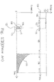
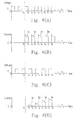
- Fig. 1(B) shows the measuring method for the conventional meter, and is also the content of Patent US 5,366,609 .
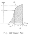
- Fig. 1(C) is the amplified diagram of scope S shown in Fig. 1(B) and shows the currents generated by the voltage applied to the electrodes on the test strip during the sample detecting period.
- a voltage 102 with a fixed value is applied to the electrodes of the test strip during a sample detecting period 101 for detecting whether a sample is present in the reaction region.
- a drop of the sample is added to the test strip at time 108.
- a sample volume delaying period 114 starts.
- the meter will continuously applies the voltage 102 to the electrodes of the test strip until time 103.
- values of current 109 is compared with a sample volume threshold 113 for determining the end of sample volume delaying period 114. If the value (intensity) of the current is lower than sample volume threshold 113, the meter will alarm to point out that the volume of the sample in the test strip is not enough, and then stops the measurement of the sample.
- the meter will start the subsequent step of performing an incubation period 105.
- the meter removes the fixed voltage 102 and does not apply any voltage, i.e. apply a zero voltage 104, to the electrodes of the test strip.
- incubation period 105 a specific and predetermined time is provided for the sample to be mixed and dissolved with the reagents coated on the electrodes.
- the meter When incubation period 105 finishes, the meter starts a measurement period 106 and apply a predetermined voltage 107 to the electrodes of the test strip during measurement period 106. During measurement period 106, the value of current 110 between the electrodes will be measured.
- the determination and the calculation of the concentration of the analyte in the sample is based on the aforementioned Cottrell current, and during measurement period 106 the value of concentration of the analyte in the sample, calculated according to the Cottrell Equation, will be shown on the display of the meter.
- sample detecting threshold 112 are very important for estimating whether the sample volume is enough.
- the present invention provides a method for estimating the distribution of a sample fluid covering on the surfaces of the electrodes of a electrochemical test apparatus, where the results of the present method can be used for estimating the percentage of the surface of the electrode covered by the sample fluid to estimate the effectiveness and/or correctness of the measurement of the concentration of the analyte in the sample. Moreover, the results of the present method can be used for estimating the above-mentioned effectiveness and/or correctness either prior to the formally measurement of the concentration of the analyte or after the measurement of the concentration of the analyte.
- a reaction DC voltage is applied to the electrochemical test apparatus having at least a first and a second electrodes during sample detecting period 101, wherein the reaction DC voltage is determined by the oxidative (or reductive) voltage which is obtained from the cyclic voltammetry and able to make the optimum oxidation (or reduction) of the electrochemical reaction occur.
- the present disclosure provides a method for a sensor having at least a first electrode and a second electrode, comprising the steps of (a) providing a target sample flowing from the first electrode to the second electrode; (b) applying a first DC voltage with a voltage value across the first electrode and the second electrode for a first duration to make a potential of the first electrode higher than a potential of the second electrode and to generate a first Cottrell current; (c) removing the first DC voltage; (d) applying a second DC voltage with a voltage value across the first electrode and the second electrode for a second duration to make the potential of the second electrode higher than the potential of the first electrode and to generate a second Cottrell current, wherein the respective voltage values of the first and the second DC voltages are equal; (e) removing the second DC voltage; (f) repeating steps (b) to (e) at least twice; (g) adding up respective values of the first Cottrell currents and respective values of the second Cottrell currents respectively; and (h) obtaining
- the present disclosure provides a determining method for a distribution of a target sample, comprising the steps of providing a first and a second electrodes; providing the target sample flowing from the first electrode to the second electrode; applying a first DC voltage having a voltage value across the first electrode and the second electrode to make a potential of the first electrode higher than a potential of the second electrode and to generate a first sensing current; removing the first DC voltage; applying a second DC voltage having the voltage value across the first electrode and the second electrode to make the potential of the second electrode higher than the potential of the first electrode and to generate a second sensing current; and obtaining a ratio of a value of the first sensing current over a value of the second sensing current to determine the distribution of the target sample on the first and the second electrodes.
- the present disclosure provides a determining method, comprising the steps of providing a first and a second electrodes; providing a target sample flowing from the first electrode to the second electrode; making a potential of the first electrode higher than a potential of the second electrode and to generate a first sensing current; making the potential of the second electrode higher than the potential of the first electrode and to generate a second sensing current; and obtaining a ratio of a value of the first sensing current over a value of the second sensing current to determine the distribution of the target sample on the first and the second electrodes.
- the present invention provides a method for estimating the distribution of a sample fluid covering on the surfaces of the electrodes of a electrochemical test apparatus to estimate the effectiveness and/or correctness of the measurement of the concentration of the analyte in the sample, and will now be described more specifically with reference to the following embodiments. It is to be noted that the following descriptions of preferred embodiments of this invention are presented herein for the purposes of illustration and description only; it is not intended to be exhaustive or to be limited to the precise form disclosed.
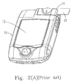
- Fig. 2(A) shows the appearance of meter 10 applied for the electrochemical test strip.
- the meter 10 includes a shell with a display 12 showing measurement results, and a slot 11 to be inserted by a sensor, e.g. an electrochemical test strip 20.
- Fig. 2(B) shows the front view (the left one) and the back view (the right one) of electrochemical test strip 20, wherein electrochemical test strip 20 has electrodes 21 and 22.
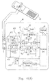
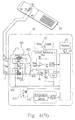
- Fig. 2(C) shows the internal circuit configuration of conventional meter 10 used for the electrochemical test strip 20.
- the divider formed by voltage regulator 121 and resistors R1 and R2 applies the voltage to contact Vc1, and current buffer 120 has a capability for driving high current and outputs a potential identical to that of contact Vc1 at contact Vc2.
- the potential of contact 125 is Vw
- the potential of contact 126 is Vc
- an electrode voltage 123 is Vwc which is equal to the potential difference between Vw and Vc. Electrode voltage 123 is applied between contacts 125 and 126 respectively electrically connected to outputting contacts 24 and 25 of electrochemical test strip 20.
- FIGs. 3(A) to 3(E) illustrate the process that the sample flows into electrochemical test strip 20 and fully covers on electrodes 21 and 22.
- Figs. 3(A) to 3(E) are sectional drawings of electrochemical test strip 20 taken along the line A-A', wherein electrochemical test strip 20 has a channel 23, outputting contacts 24 and 25, a sample entrance 26, a cover 27, an air hole 28, a sample 29, a groove 210, upper surfaces of electrodes 211 and 212, through holes 213 and reagent 214, electrodes 21 and 22 are configured in through holes 213 in groove 210 of electrochemical test strip 20, and the respective areas of upper surfaces 211 and 212 are the same. Electrodes 21 and 22 are tightly surrounded by through holes 213 without any gap. The diameters of through holes 213 are designed to be slightly smaller than that of electrodes 21 or 22, so that electrodes 21 and 22 can be mechanically engaged in through holes 213.
- Respective upper surfaces 211 and 212 of electrodes 21 and 22 form the working area of electrode, and respective sizes of upper surfaces 211 and 212 can be the same to or different from each other.
- the bottoms of electrodes 21 and 22 are outputting contacts 24 and 25 of electrochemical test strip 20, and outputting contacts 24 and 25 respectively connected to contacts 125 and 126 of meter 10 as shown in Fig. 2(C) .
- Cover 27 is a hydrophilic one and has air hole 28 linked with the outside world. Cover 27 is further configured to cover groove 23 to form channel 23, wherein channel 23 is a capillary and defines a reaction region which is coated with reagent 214, and reagent 214 is covered on upper surfaces 211 and 212 of electrodes 21 and 22.
- Reagent 214 includes a known oxidative or reductive enzyme such as a glucose oxidase, an electron transport intermediate such as the potassium ferrocyanide (Fe(CN)63-), as well as some hydrophilic chemicals.
- a known oxidative or reductive enzyme such as a glucose oxidase
- an electron transport intermediate such as the potassium ferrocyanide (Fe(CN)63-)
- the compositions of reagent 214 are the common means and not the focal point of the present invention.
- electrochemical test strip 20 provides sample entrance 26 for receiving sample 29, e.g. a drop of blood.
- FIG. 3(B) When placed on the opening of sample entrance 26, sample 29 will automatically be sucked into channel 23 due to the capillarity and/or the hydrophilic interaction.
- Figs. 3(B) to 3(E) show the flowing process of sample 29 in channel 23.
- sample 29 When sufficient sample 29 is dropped to the opening of sample entrance 26, sample 29 will flow along channel 23 as shown in Figs. 3(C) and 3(D) until totally covers electrodes 21 and 22 as shown in Fig. 3(E) , in the meanwhile the air in channel 23 is discharged through air hole 28.
- meter 10 needs to estimate whether the value of the sensing current between electrodes 21 and 22 achieves sample detecting threshold 112, and the determination of sample detecting threshold 112 is very important.
- sample detecting threshold 112 is too high, the value of the sensing current will not achieve sample detecting threshold 112 and meter 10 will not start the procedures of incubation period 105 and measurement period 106 even channel 23 is full of sample 29 as shown in Figs. 3(D) or 3(E) . Moreover, the factors such as the hematocrit (HCT), or the contents of oxygen, glucose or lipid in the sample blood will interfere the sensing current, so that the value of the sensing current may be unable to achieve sample detecting threshold 112.
- HCT hematocrit
- the method which can correctively estimate whether the volume of sample in the reaction region is sufficient to obtain a correct sensing current is very important for such the meter.
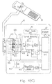
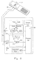
- FIG. 4(A) shows the schematic diagram of the internal circuit of the present meter 40 suitable for electrochemical test strip 20.
- the present meter 40 shown in Fig. 4(A) and the following figures has an appearance identical to that of the conventional one, e.g. meter 20, the internal circuit and the measuring method of the present meter 40 are much advanced than that of the conventional one.
- electrochemical test strip 20 in Fig. 4(A) it has been illustrated as above and will not repeat in the following passages.
- Fig. 4(A) shows the internal configuration of meter 40.
- the divider formed by voltage regulator 49 and resistors R1 and R2 applies the voltage to contact Vc1, and current buffer 48 has a capability for driving high current and outputs a potential identical to that of contact Vc1 at contact Vc2.
- the potential of contact 413 is Vw
- the potential of contact 414 is Vc
- a working voltage 411 is Vwc which is equal to the potential difference between Vw and Vc and applied between contacts 413 and 414.
- Switch set 420 has four switches S1, S2, S3 and S4, each of these four switches can be selected from a mechanical relay, an electronic type of analog switch and a MOSFET or a bipolar transistor to form a bridge switch for performing the switch.
- the voltage switching unit 415 includes a control contact 416 for receiving the digital control signal transmitted from processor unit 41, and controlling the turn on/off of switches S1 and S4 accordingly. If the digital control signal received by control contact 416 is 1, both of switches S1 and S4 will be turned on. On the contrary, if the digital control signal received by control contact 416 is 0, both of switches S1 and S4 will turn off.
- Voltage switching unit 415 also includes an inventor 417 which is a basic component of the digital or the logic circuits and used to reverse the input signal. On the binary logic, if the input signal is 0, the output signal is 1; and when the input signal is 1, the output signal is 0.
- Such the principle is used to control the turn on/off of switches S2 and S3 and makes the time that switches S2 and S3 are turned off to be always different from that of switches S1 and S4. In other words, only one of switches S2 and S3, or switches S1 and S4 can be turned off (turned on) at a time.
- the control of voltage switching unit 415 is described as follows. As shown in Fig. 4(B) , when processor unit 41 provides a digital signal 1 to control contact 416, the potentials of output X and contact 413 are the same since switch S1 is turned on, and the potentials of output X and contact 413 are Vx and Vw respectively; and the potentials of output Y and contact 414 are the same since switch S4 is turned on, and the potentials of output Y and contact 414 are Vy and Vc respectively.
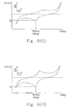
- Figs. 5(A) to 5(G) and 6(A) to 6(I) show an embodiment of the present method, wherein Figs. 5(A) to 5(G) are partially amplified diagrams of electrochemical test strip 20. The procedures of the present method are described as follows.
- the preferable range of ratio for estimating the distribution of sample on the electrodes is obtained from the experiments of which samples having various volumes are used. The details of these experiments are described as follows.
- the sample volume is too small, e.g. 0.3 ⁇ L, the Cottrell current is unable to be generated since the sample volume of 0.3 ⁇ L is insufficient for the sample flowing from the first electrode to contact the second electrode.
- the first Cottrell current can be obtained when the sample volume is 0.4 ⁇ L, the CV% is poor (where CV% > 10%).
- the CV% of the first Cottrell current is preferable and acceptable (where CV% ⁇ 5%), and the ranges of ratio of the first Cottrell current/the second Cottrell current, and the second Cottrell current/the first Cottrell current are 0.3 to 1.7 and 0.6 to 3.3 respectively.
- CV% ⁇ 5% the ranges of ratio of the first Cottrell current/the second Cottrell current, and the second Cottrell current/the first Cottrell current are 0.3 to 1.7 and 0.6 to 3.3 respectively.
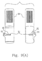
- Figs. 7(A) and 7(B) show another embodiment of the present invention, where the configuration of voltage switching unit 715 is different from that of voltage switching unit 415 as shown in Fig. 4(B) .
- Voltage switching unit 715 receives the control signals transmitted from processor unit 701 by a control contact 716 and switches the switches S1, S2 and S3 accordingly, which is described as follows.
- R1 is defined as the same as R2
- the voltage differences Vxy under the mode of S1 connected to S2 and the voltage under the mode of S1 connected to S3 have the same value and the respective polarities thereof are inversed.
- the value of sensing current shown in Figs. 6(A) to 6(I) can also be obtained accordingly so as to estimate whether the sample volume is sufficient for the test strip.
- Fig. 8 shows another embodiment of the present invention, where the configuration of voltage switching unit 815 is different from those of voltage switching units 415 and 715.
- Vx voltage on output X
- Vr voltage on contact 811
- voltage switching unit 815 receives the control signals transmitted from processor unit 801, converts the control signal into the analog voltage by a digital-to-analog voltage converter 816, provides the analog voltage Vc1 to contact 812 and enhances the output driving force of the current by a current buffer OP2.
- Vy equals to Vc1 and Vy is adjusted by the control signals of processor unit 801 to achieve the switch of the voltage.
- the absolute value of the working voltage Vxy applied between outputs X and Y is predetermined as Q.
- Vc1 is adjusted and switched according to the digital control signals transmitted from processor unit 801 at the first and the second times, and the value of sensing current shown in Figs. 6(A) to 6(I) can also be obtained accordingly so as to estimate whether the sample volume is sufficient for the test strip.
- the sensing current is estimated whether achieves sample detecting threshold 112. If the sensing current achieves sample detecting threshold 112, the standard procedures from incubation period 105 to measurement period 106 are performed.
- the switch of voltage as mentioned in the above embodiments can be performed at any time within incubation period 105 to measurement period 106, and Ix and Iy are obtained for further operating by processor units 41, 701 and 801.
- the effectiveness of the operating results at or after the end of measurement period is further confirmed based on the steps disclosed in the above embodiments.
- the present method can be performed at any time within sample detecting period 101, incubation period 105 and measurement period 106 to estimate the effectiveness of the operating results at or after the end of measurement period.
- Electrochemical test strip 90 has two electrodes 91 and 92 and a reference electrode 93, wherein each of electrodes 91 and 92 will be the working electrode at a specific time when the voltage switching unit (415, 715 or 815) operates as above-mentioned and the Cottrell current is generated accordingly.
- reference electrode 93 assists in further stabilizing predetermined voltage 107 applied to electrodes 91 and 92 during measurement period 106 to obtain a more accurate sensing current.
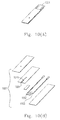
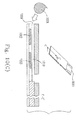
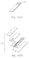
- Figs. 10(A) to 10(D) and Figs. 11 (A) to 11 (C) respectively show electrochemical test strips 1001 and 1101, each of which has the thin-film electrodes.
- Figs. 10(C) and (D) are sectional drawings of electrochemical test strip 1001 taken along the line C-C'.
- Figs. 11 (C) is a sectional drawing of electrochemical test strip 1101 taken along the line D-D'.
- the formations and the structures of electrochemical test strips 1001 and 1101 are disclosed in US 5,997,817 , US 5,985,116 and EP 1098000 , and thin film electrodes 1002, 1003, 1102, 1103 and 1104 can be formed by the screen printing or the metal deposition.
- Fig. 10(C) when a blood sample 1008 starts to flow into channel 1010 of electrochemical test strip 1001 from sample entrance 1009, there will no sensing current be generated. However, with blood sample 1008 further flowing to cover electrode 1002 and contact electrode 1003 as shown in Fig. 10(D) , the value of sensing current shown in Figs. 6(A) to 6(I) can also be obtained accordingly so as to estimate whether the sample volume is sufficient for electrochemical test strip 1001.
- FIGs. 11 (A) to 11 (C) A preferable embodiment is shown in Figs. 11 (A) to 11 (C) , where electrochemical test strip 1101 has a third thin-file electrode 1104 which is a thin-film reference electrode. Based on the present methods as above-mentioned, the value of sensing current shown in Figs. 6(A) to 6(I) can also be obtained accordingly so as to estimate whether the sample volume is sufficient for electrochemical test strip 1101.
Landscapes
- Health & Medical Sciences (AREA)
- Life Sciences & Earth Sciences (AREA)
- Chemical & Material Sciences (AREA)
- Biochemistry (AREA)
- Chemical Kinetics & Catalysis (AREA)
- Electrochemistry (AREA)
- Physics & Mathematics (AREA)
- Analytical Chemistry (AREA)
- Molecular Biology (AREA)
- General Health & Medical Sciences (AREA)
- General Physics & Mathematics (AREA)
- Immunology (AREA)
- Pathology (AREA)
- Hematology (AREA)
- Biophysics (AREA)
- Investigating Or Analysing Biological Materials (AREA)
Claims (13)
- Bestimmungsverfahren für eine Verteilung einer Zielstichprobe (29, 1008), gekennzeichnet durch die folgenden Schritte:(a) Bereitstellen einer ersten Elektrode (21, 91, 1002) und einer zweiten Elektrode (22, 92, 1003);(b) Bereitstellen der Zielstichprobe (29, 1008), die von der ersten Elektrode (21, 91, 1002) zu der zweiten Elektrode (22, 92, 1003) fließt;(c) Anlegen einer ersten Gleichspannung mit einem Spannungswert zwischen der ersten Elektrode (21, 91, 1002) und der zweiten Elektrode (22, 92, 1003), damit ein Potential der ersten Elektrode (21, 91, 1002) höher als ein Potential der zweiten Elektrode (22, 92, 1003) wird, und um einen ersten Cottrell-Strom zu erzeugen;(d) Entfernen der ersten Gleichspannung;(e) Anlegen einer zweiten Gleichspannung mit dem Spannungswert zwischen der ersten Elektrode (21, 91, 1002) und der zweiten Elektrode (22, 92, 1003), damit das Potential der zweiten Elektrode (22, 92, 1003) höher als das Potential der ersten Elektrode (21, 91, 1002) wird, und um einen zweiten Cottrell-Strom zu erzeugen; und(f) Erhalten eines Verhältnisses eines Werts des ersten Cottrell-Stroms geteilt durch einen Wert des zweiten Cottrell-Stroms, um die Verteilung der Zielstichprobe (29, 1008) auf der ersten Elektrode (21, 91, 1002) und der zweiten Elektrode (22, 92, 1003) zu bestimmen.
- Verfahren nach Anspruch 1, dadurch gekennzeichnet, dass es ferner die folgenden Schritte umfasst:(e1) Entfernen der zweiten Gleichspannung;(e2) mindestens zweimaliges Wiederholen der Schritte (b) bis (e);(f1) Aufaddieren jeweiliger Werte der ersten Cottrell-Ströme bzw. jeweiliger Werte der zweiten Cottrell-Ströme; und(f2) Erhalten eines Verhältnisses einer Summe der jeweiligen Werte der ersten Cottrell-Ströme geteilt durch eine Summe der jeweiligen Werte der zweiten Cottrell-Ströme, um die Verteilung der Zielstichprobe (29, 1008) auf der ersten Elektrode (21, 91, 1002) und der zweiten Elektrode (22, 92, 1003) zu bestimmen.
- Verfahren nach Anspruch 2, dadurch gekennzeichnet, dass die erste und zweite Gleichspannung für eine erste bzw. eine zweite Dauer angelegt werden und die erste und zweite Dauer von 3 ms bis 2 s betragen.
- Verfahren nach Anspruch 3, dadurch gekennzeichnet, dass der Wert des ersten Cottrell-Stroms und der Wert des zweiten Cottrell-Stroms während der ersten bzw. der zweiten Dauer aufgezeichnet werden.
- Verfahren nach Anspruch 2, dadurch gekennzeichnet, dass die erste und zweite Gleichspannung für eine erste Entfernungs- bzw. eine zweite Entfernungsdauer entfernt werden und die erste Entfernungs- und die zweite Entfernungsdauer zwischen 0 ms bis 50 ms betragen.
- Verfahren nach Anspruch 1, dadurch gekennzeichnet, dass die erste und zweite Gleichspannung über zyklische Voltamogramme bestimmt werden und S/N-Verhältnisse der ersten Gleichspannung und der zweiten Gleichspannung nicht kleiner als 1 sind.
- Verfahren nach Anspruch 1, dadurch gekennzeichnet, dass die erste Elektrode (21, 91, 1002) und die zweite Elektrode (22, 92, 1003) auf einem Sensor (20, 1001, 1101) konfiguriert sind.
- Verfahren nach Anspruch 1, dadurch gekennzeichnet, dass die erste Elektrode (21, 91, 1002) und die zweite Elektrode (22, 92, 1003) ein Enzym und einen Elektronentransfervermittler darauf aufweisen und das Enzym bewirkt, dass die Zielstichprobe (29, 1008) eine Reaktion erzeugt, die eine aus einer Gruppe bestehend aus Oxidation, Reduktion und Redox ausgewählte ist.
- Verfahren nach Anspruch 1, dadurch gekennzeichnet, dass die erste und zweite Gleichspannung für eine erste bzw. eine zweite Dauer angelegt werden und die erste und zweite Dauer von 3 ms bis 2 s betragen.
- Verfahren nach Anspruch 1, dadurch gekennzeichnet, dass die erste Elektrode (21, 91, 1002) und die zweite Elektrode (22, 92, 1003) jeweilige elektrochemische Reaktionsflächen (211, 212) aufweisen, die einander gleich sind.
- Verfahren nach Anspruch 10, dadurch gekennzeichnet, dass sowohl die erste Elektrode (21, 91, 1002) als auch die zweite Elektrode (22, 92, 1003) darauf voll durch die Zielstichprobe (29, 1008) bedeckt werden, wenn das Verhältnis 1 ist.
- Verfahren nach Anspruch 1, dadurch gekennzeichnet, dass die erste Elektrode (21, 91, 1002) und die zweite Elektrode (22, 92, 1003) jeweilige elektrochemische Reaktionsflächen (211, 212) aufweisen und die elektrochemische Reaktionsfläche (211) der ersten Elektrode (21, 91, 1002) nicht gleich der der zweiten Elektrode (22, 92, 1003) ist.
- Verfahren nach Anspruch 1, dadurch gekennzeichnet, dass es zum Bestimmen einer Effektivität einer Detektion gegenüber der Zielstichprobe (29, 1008) verwendet wird.
Applications Claiming Priority (1)
| Application Number | Priority Date | Filing Date | Title |
|---|---|---|---|
| TW098111902A TWI388823B (zh) | 2009-04-09 | 2009-04-09 | 一種判斷樣品佈滿狀況的偵測方法 |
Publications (2)
| Publication Number | Publication Date |
|---|---|
| EP2239563A1 EP2239563A1 (de) | 2010-10-13 |
| EP2239563B1 true EP2239563B1 (de) | 2016-04-06 |
Family
ID=42272495
Family Applications (1)
| Application Number | Title | Priority Date | Filing Date |
|---|---|---|---|
| EP10159447.1A Not-in-force EP2239563B1 (de) | 2009-04-09 | 2010-04-09 | Verfahren zur Einschätzung der Verteilung einer Probe |
Country Status (3)
| Country | Link |
|---|---|
| US (2) | US20100258453A1 (de) |
| EP (1) | EP2239563B1 (de) |
| TW (1) | TWI388823B (de) |
Families Citing this family (14)
| Publication number | Priority date | Publication date | Assignee | Title |
|---|---|---|---|---|
| CN101887047A (zh) * | 2009-05-12 | 2010-11-17 | 华广生技股份有限公司 | 一种判断样品布满状况的侦测方法 |
| TWI576583B (zh) * | 2013-08-02 | 2017-04-01 | 達爾生技股份有限公司 | 生化檢測試片的判斷方法 |
| CN105092662B (zh) * | 2014-05-20 | 2019-01-22 | 光宏精密股份有限公司 | 电化学感应试片及其制造方法 |
| TWI531790B (zh) | 2014-11-10 | 2016-05-01 | 五鼎生物技術股份有限公司 | 電化學試片、測量系統及判斷電化學試片反應區的樣品容量的方法 |
| TWI596335B (zh) * | 2015-09-23 | 2017-08-21 | 達爾生技股份有限公司 | 電化學感測試片之檢測方法及檢測裝置 |
| US11690566B2 (en) * | 2017-11-21 | 2023-07-04 | MX3 Diagnostics, Inc. | Saliva testing system |
| US12019045B2 (en) | 2018-10-11 | 2024-06-25 | MX3 Diagnostics, Inc. | Ion selective sensor |
| USD874007S1 (en) * | 2018-10-25 | 2020-01-28 | Bionime Corporation | Analyte measurement apparatus |
| US11701036B2 (en) | 2019-07-10 | 2023-07-18 | MX3 Diagnostics, Inc. | Saliva test strip and method |
| EP4090243A4 (de) | 2020-01-15 | 2023-12-20 | MX3 Diagnostics, Inc. | Bewertung der konzentration von biomarkern in einem fluid |
| JP7699138B2 (ja) | 2020-01-30 | 2025-06-26 | エムエックススリー・ダイアグノスティクス・インコーポレイテッド | 生体液試料の評価 |
| CA3207259A1 (en) * | 2021-02-19 | 2022-08-25 | Yiheng QIN | Assay sample volume normalization |
| TWI799926B (zh) * | 2021-07-28 | 2023-04-21 | 五鼎生物技術股份有限公司 | 電化學檢測系統、測量儀及電化學檢測方法 |
| TWD223565S (zh) * | 2022-03-04 | 2023-02-11 | 華廣生技股份有限公司 | 生理訊號量測裝置 |
Family Cites Families (15)
| Publication number | Priority date | Publication date | Assignee | Title |
|---|---|---|---|---|
| JPH0820412B2 (ja) * | 1990-07-20 | 1996-03-04 | 松下電器産業株式会社 | 使い捨てセンサを用いた定量分析方法、及び装置 |
| US5352351A (en) * | 1993-06-08 | 1994-10-04 | Boehringer Mannheim Corporation | Biosensing meter with fail/safe procedures to prevent erroneous indications |
| US5366609A (en) * | 1993-06-08 | 1994-11-22 | Boehringer Mannheim Corporation | Biosensing meter with pluggable memory key |
| AUPN661995A0 (en) * | 1995-11-16 | 1995-12-07 | Memtec America Corporation | Electrochemical cell 2 |
| US6878251B2 (en) * | 1998-03-12 | 2005-04-12 | Lifescan, Inc. | Heated electrochemical cell |
| KR100340173B1 (ko) | 2000-03-22 | 2002-06-12 | 이동준 | 전기화학적 바이오센서 측정기 |
| US7491310B2 (en) * | 2001-10-12 | 2009-02-17 | Arkray, Inc. | Concentration measuring method and concentration measuring apparatus |
| US6856125B2 (en) * | 2001-12-12 | 2005-02-15 | Lifescan, Inc. | Biosensor apparatus and method with sample type and volume detection |
| US7556724B2 (en) * | 2005-02-10 | 2009-07-07 | Bionime Corporation | Electrochemical sensor strip and manufacturing method thereof |
| US7547382B2 (en) * | 2005-04-15 | 2009-06-16 | Agamatrix, Inc. | Determination of partial fill in electrochemical strips |
| US20070017824A1 (en) * | 2005-07-19 | 2007-01-25 | Rippeth John J | Biosensor and method of manufacture |
| WO2007040913A1 (en) * | 2005-09-30 | 2007-04-12 | Bayer Healthcare Llc | Gated voltammetry |
| EP1860432B1 (de) * | 2006-05-24 | 2017-12-13 | Bionime GmbH | Verfahren zum Betrieb eines Messgeräts und Messgerät |
| EP2082222B1 (de) * | 2006-10-05 | 2012-11-21 | Lifescan Scotland Limited | Systeme und verfahren zur bestimmung einer weitgehend hämatokrit-unabhängigen analytkonzentration |
| US8388821B2 (en) * | 2006-10-05 | 2013-03-05 | Lifescan Scotland Limited | Method for determining hematocrit corrected analyte concentrations |
-
2009
- 2009-04-09 TW TW098111902A patent/TWI388823B/zh active
-
2010
- 2010-04-09 EP EP10159447.1A patent/EP2239563B1/de not_active Not-in-force
- 2010-04-09 US US12/757,695 patent/US20100258453A1/en not_active Abandoned
-
2016
- 2016-10-21 US US15/299,605 patent/US10197523B2/en active Active
Also Published As
| Publication number | Publication date |
|---|---|
| TWI388823B (zh) | 2013-03-11 |
| US20170038330A1 (en) | 2017-02-09 |
| EP2239563A1 (de) | 2010-10-13 |
| US20100258453A1 (en) | 2010-10-14 |
| US10197523B2 (en) | 2019-02-05 |
| TW201037301A (en) | 2010-10-16 |
Similar Documents
| Publication | Publication Date | Title |
|---|---|---|
| EP2239563B1 (de) | Verfahren zur Einschätzung der Verteilung einer Probe | |
| US7547382B2 (en) | Determination of partial fill in electrochemical strips | |
| EP1688742B1 (de) | Elektrochemischer Biosensor | |
| US7771583B2 (en) | Electrochemical determination of analytes | |
| US8192610B2 (en) | Error detection in analyte measurements based on measurement of system resistance | |
| JP4256588B2 (ja) | 統計的手法を用いた電気化学的測定方法および測定装置 | |
| EP0679720A1 (de) | Verfahren zur Quantifizierung von spezifischen Verbindungen | |
| US8882987B2 (en) | Biosensor measurement system and method for detecting abnormal waveform in biosensor | |
| EP0882226A1 (de) | Elektrochemisches verfahren | |
| EP1869455A2 (de) | Verfahren und vorrichtung für den nachweis abnormaler spuren bei der elektrochemischen analytdetektion | |
| AU2006233771A1 (en) | Method for determination of analyte concentrations and related apparatus | |
| US20130098776A1 (en) | Method and Sensor Strip for Analysis of a Sample | |
| US7678261B2 (en) | Apparatus and method for measuring reaction result of samples on biosensor | |
| KR101861993B1 (ko) | 커패시턴스를 사용하여 대조 시료와 시험 유체를 식별하는 시스템 및 방법 | |
| CN101887047A (zh) | 一种判断样品布满状况的侦测方法 | |
| US8702923B2 (en) | Method and apparatus for measuring sample reaction results on biosensor | |
| KR102209132B1 (ko) | 전기화학 바이오센서 에러 판별 장치 및 방법 | |
| AU2011202737B2 (en) | Determination of partial fill in electrochemical strips | |
| HK1146302A (en) | Rapid-read gated amperometry |
Legal Events
| Date | Code | Title | Description |
|---|---|---|---|
| PUAI | Public reference made under article 153(3) epc to a published international application that has entered the european phase |
Free format text: ORIGINAL CODE: 0009012 |
|
| AK | Designated contracting states |
Kind code of ref document: A1 Designated state(s): AT BE BG CH CY CZ DE DK EE ES FI FR GB GR HR HU IE IS IT LI LT LU LV MC MK MT NL NO PL PT RO SE SI SK SM TR |
|
| AX | Request for extension of the european patent |
Extension state: AL BA ME RS |
|
| 17P | Request for examination filed |
Effective date: 20110412 |
|
| GRAP | Despatch of communication of intention to grant a patent |
Free format text: ORIGINAL CODE: EPIDOSNIGR1 |
|
| INTG | Intention to grant announced |
Effective date: 20151023 |
|
| GRAS | Grant fee paid |
Free format text: ORIGINAL CODE: EPIDOSNIGR3 |
|
| GRAA | (expected) grant |
Free format text: ORIGINAL CODE: 0009210 |
|
| AK | Designated contracting states |
Kind code of ref document: B1 Designated state(s): AT BE BG CH CY CZ DE DK EE ES FI FR GB GR HR HU IE IS IT LI LT LU LV MC MK MT NL NO PL PT RO SE SI SK SM TR |
|
| REG | Reference to a national code |
Ref country code: GB Ref legal event code: FG4D |
|
| REG | Reference to a national code |
Ref country code: AT Ref legal event code: REF Ref document number: 788346 Country of ref document: AT Kind code of ref document: T Effective date: 20160415 Ref country code: CH Ref legal event code: EP |
|
| REG | Reference to a national code |
Ref country code: IE Ref legal event code: FG4D |
|
| REG | Reference to a national code |
Ref country code: DE Ref legal event code: R096 Ref document number: 602010031983 Country of ref document: DE |
|
| REG | Reference to a national code |
Ref country code: LT Ref legal event code: MG4D Ref country code: NL Ref legal event code: MP Effective date: 20160406 |
|
| REG | Reference to a national code |
Ref country code: AT Ref legal event code: MK05 Ref document number: 788346 Country of ref document: AT Kind code of ref document: T Effective date: 20160406 |
|
| PG25 | Lapsed in a contracting state [announced via postgrant information from national office to epo] |
Ref country code: BE Free format text: LAPSE BECAUSE OF NON-PAYMENT OF DUE FEES Effective date: 20160430 |
|
| PG25 | Lapsed in a contracting state [announced via postgrant information from national office to epo] |
Ref country code: NL Free format text: LAPSE BECAUSE OF FAILURE TO SUBMIT A TRANSLATION OF THE DESCRIPTION OR TO PAY THE FEE WITHIN THE PRESCRIBED TIME-LIMIT Effective date: 20160406 |
|
| PG25 | Lapsed in a contracting state [announced via postgrant information from national office to epo] |
Ref country code: FI Free format text: LAPSE BECAUSE OF FAILURE TO SUBMIT A TRANSLATION OF THE DESCRIPTION OR TO PAY THE FEE WITHIN THE PRESCRIBED TIME-LIMIT Effective date: 20160406 Ref country code: PL Free format text: LAPSE BECAUSE OF FAILURE TO SUBMIT A TRANSLATION OF THE DESCRIPTION OR TO PAY THE FEE WITHIN THE PRESCRIBED TIME-LIMIT Effective date: 20160406 Ref country code: LT Free format text: LAPSE BECAUSE OF FAILURE TO SUBMIT A TRANSLATION OF THE DESCRIPTION OR TO PAY THE FEE WITHIN THE PRESCRIBED TIME-LIMIT Effective date: 20160406 Ref country code: IS Free format text: LAPSE BECAUSE OF FAILURE TO SUBMIT A TRANSLATION OF THE DESCRIPTION OR TO PAY THE FEE WITHIN THE PRESCRIBED TIME-LIMIT Effective date: 20160806 Ref country code: NO Free format text: LAPSE BECAUSE OF FAILURE TO SUBMIT A TRANSLATION OF THE DESCRIPTION OR TO PAY THE FEE WITHIN THE PRESCRIBED TIME-LIMIT Effective date: 20160706 |
|
| PG25 | Lapsed in a contracting state [announced via postgrant information from national office to epo] |
Ref country code: GR Free format text: LAPSE BECAUSE OF FAILURE TO SUBMIT A TRANSLATION OF THE DESCRIPTION OR TO PAY THE FEE WITHIN THE PRESCRIBED TIME-LIMIT Effective date: 20160707 Ref country code: LV Free format text: LAPSE BECAUSE OF FAILURE TO SUBMIT A TRANSLATION OF THE DESCRIPTION OR TO PAY THE FEE WITHIN THE PRESCRIBED TIME-LIMIT Effective date: 20160406 Ref country code: PT Free format text: LAPSE BECAUSE OF FAILURE TO SUBMIT A TRANSLATION OF THE DESCRIPTION OR TO PAY THE FEE WITHIN THE PRESCRIBED TIME-LIMIT Effective date: 20160808 Ref country code: SE Free format text: LAPSE BECAUSE OF FAILURE TO SUBMIT A TRANSLATION OF THE DESCRIPTION OR TO PAY THE FEE WITHIN THE PRESCRIBED TIME-LIMIT Effective date: 20160406 Ref country code: HR Free format text: LAPSE BECAUSE OF FAILURE TO SUBMIT A TRANSLATION OF THE DESCRIPTION OR TO PAY THE FEE WITHIN THE PRESCRIBED TIME-LIMIT Effective date: 20160406 Ref country code: ES Free format text: LAPSE BECAUSE OF FAILURE TO SUBMIT A TRANSLATION OF THE DESCRIPTION OR TO PAY THE FEE WITHIN THE PRESCRIBED TIME-LIMIT Effective date: 20160406 Ref country code: AT Free format text: LAPSE BECAUSE OF FAILURE TO SUBMIT A TRANSLATION OF THE DESCRIPTION OR TO PAY THE FEE WITHIN THE PRESCRIBED TIME-LIMIT Effective date: 20160406 |
|
| REG | Reference to a national code |
Ref country code: CH Ref legal event code: PL |
|
| PG25 | Lapsed in a contracting state [announced via postgrant information from national office to epo] |
Ref country code: IT Free format text: LAPSE BECAUSE OF FAILURE TO SUBMIT A TRANSLATION OF THE DESCRIPTION OR TO PAY THE FEE WITHIN THE PRESCRIBED TIME-LIMIT Effective date: 20160406 Ref country code: BE Free format text: LAPSE BECAUSE OF FAILURE TO SUBMIT A TRANSLATION OF THE DESCRIPTION OR TO PAY THE FEE WITHIN THE PRESCRIBED TIME-LIMIT Effective date: 20160406 |
|
| REG | Reference to a national code |
Ref country code: DE Ref legal event code: R097 Ref document number: 602010031983 Country of ref document: DE |
|
| REG | Reference to a national code |
Ref country code: IE Ref legal event code: MM4A |
|
| PG25 | Lapsed in a contracting state [announced via postgrant information from national office to epo] |
Ref country code: RO Free format text: LAPSE BECAUSE OF FAILURE TO SUBMIT A TRANSLATION OF THE DESCRIPTION OR TO PAY THE FEE WITHIN THE PRESCRIBED TIME-LIMIT Effective date: 20160406 Ref country code: CZ Free format text: LAPSE BECAUSE OF FAILURE TO SUBMIT A TRANSLATION OF THE DESCRIPTION OR TO PAY THE FEE WITHIN THE PRESCRIBED TIME-LIMIT Effective date: 20160406 Ref country code: LI Free format text: LAPSE BECAUSE OF NON-PAYMENT OF DUE FEES Effective date: 20160430 Ref country code: MC Free format text: LAPSE BECAUSE OF FAILURE TO SUBMIT A TRANSLATION OF THE DESCRIPTION OR TO PAY THE FEE WITHIN THE PRESCRIBED TIME-LIMIT Effective date: 20160406 Ref country code: CH Free format text: LAPSE BECAUSE OF NON-PAYMENT OF DUE FEES Effective date: 20160430 Ref country code: SK Free format text: LAPSE BECAUSE OF FAILURE TO SUBMIT A TRANSLATION OF THE DESCRIPTION OR TO PAY THE FEE WITHIN THE PRESCRIBED TIME-LIMIT Effective date: 20160406 Ref country code: DK Free format text: LAPSE BECAUSE OF FAILURE TO SUBMIT A TRANSLATION OF THE DESCRIPTION OR TO PAY THE FEE WITHIN THE PRESCRIBED TIME-LIMIT Effective date: 20160406 Ref country code: EE Free format text: LAPSE BECAUSE OF FAILURE TO SUBMIT A TRANSLATION OF THE DESCRIPTION OR TO PAY THE FEE WITHIN THE PRESCRIBED TIME-LIMIT Effective date: 20160406 |
|
| PLBE | No opposition filed within time limit |
Free format text: ORIGINAL CODE: 0009261 |
|
| STAA | Information on the status of an ep patent application or granted ep patent |
Free format text: STATUS: NO OPPOSITION FILED WITHIN TIME LIMIT |
|
| PG25 | Lapsed in a contracting state [announced via postgrant information from national office to epo] |
Ref country code: SM Free format text: LAPSE BECAUSE OF FAILURE TO SUBMIT A TRANSLATION OF THE DESCRIPTION OR TO PAY THE FEE WITHIN THE PRESCRIBED TIME-LIMIT Effective date: 20160406 |
|
| 26N | No opposition filed |
Effective date: 20170110 |
|
| REG | Reference to a national code |
Ref country code: FR Ref legal event code: ST Effective date: 20170213 |
|
| GBPC | Gb: european patent ceased through non-payment of renewal fee |
Effective date: 20160706 |
|
| PG25 | Lapsed in a contracting state [announced via postgrant information from national office to epo] |
Ref country code: FR Free format text: LAPSE BECAUSE OF NON-PAYMENT OF DUE FEES Effective date: 20160606 |
|
| PG25 | Lapsed in a contracting state [announced via postgrant information from national office to epo] |
Ref country code: IE Free format text: LAPSE BECAUSE OF NON-PAYMENT OF DUE FEES Effective date: 20160409 Ref country code: SI Free format text: LAPSE BECAUSE OF FAILURE TO SUBMIT A TRANSLATION OF THE DESCRIPTION OR TO PAY THE FEE WITHIN THE PRESCRIBED TIME-LIMIT Effective date: 20160406 Ref country code: GB Free format text: LAPSE BECAUSE OF NON-PAYMENT OF DUE FEES Effective date: 20160706 |
|
| PG25 | Lapsed in a contracting state [announced via postgrant information from national office to epo] |
Ref country code: CY Free format text: LAPSE BECAUSE OF FAILURE TO SUBMIT A TRANSLATION OF THE DESCRIPTION OR TO PAY THE FEE WITHIN THE PRESCRIBED TIME-LIMIT Effective date: 20160406 Ref country code: HU Free format text: LAPSE BECAUSE OF FAILURE TO SUBMIT A TRANSLATION OF THE DESCRIPTION OR TO PAY THE FEE WITHIN THE PRESCRIBED TIME-LIMIT; INVALID AB INITIO Effective date: 20100409 |
|
| PG25 | Lapsed in a contracting state [announced via postgrant information from national office to epo] |
Ref country code: MT Free format text: LAPSE BECAUSE OF NON-PAYMENT OF DUE FEES Effective date: 20160430 Ref country code: LU Free format text: LAPSE BECAUSE OF NON-PAYMENT OF DUE FEES Effective date: 20160409 Ref country code: TR Free format text: LAPSE BECAUSE OF FAILURE TO SUBMIT A TRANSLATION OF THE DESCRIPTION OR TO PAY THE FEE WITHIN THE PRESCRIBED TIME-LIMIT Effective date: 20160406 Ref country code: MK Free format text: LAPSE BECAUSE OF FAILURE TO SUBMIT A TRANSLATION OF THE DESCRIPTION OR TO PAY THE FEE WITHIN THE PRESCRIBED TIME-LIMIT Effective date: 20160406 |
|
| PG25 | Lapsed in a contracting state [announced via postgrant information from national office to epo] |
Ref country code: BG Free format text: LAPSE BECAUSE OF FAILURE TO SUBMIT A TRANSLATION OF THE DESCRIPTION OR TO PAY THE FEE WITHIN THE PRESCRIBED TIME-LIMIT Effective date: 20160406 |
|
| PGFP | Annual fee paid to national office [announced via postgrant information from national office to epo] |
Ref country code: DE Payment date: 20240418 Year of fee payment: 15 |
|
| REG | Reference to a national code |
Ref country code: DE Ref legal event code: R119 Ref document number: 602010031983 Country of ref document: DE |
|
| PG25 | Lapsed in a contracting state [announced via postgrant information from national office to epo] |
Ref country code: DE Free format text: LAPSE BECAUSE OF NON-PAYMENT OF DUE FEES Effective date: 20251104 |