EP1860432B1 - Verfahren zum Betrieb eines Messgeräts und Messgerät - Google Patents
Verfahren zum Betrieb eines Messgeräts und Messgerät Download PDFInfo
- Publication number
- EP1860432B1 EP1860432B1 EP06114494.5A EP06114494A EP1860432B1 EP 1860432 B1 EP1860432 B1 EP 1860432B1 EP 06114494 A EP06114494 A EP 06114494A EP 1860432 B1 EP1860432 B1 EP 1860432B1
- Authority
- EP
- European Patent Office
- Prior art keywords
- voltage
- sample
- current
- during
- electrodes
- Prior art date
- Legal status (The legal status is an assumption and is not a legal conclusion. Google has not performed a legal analysis and makes no representation as to the accuracy of the status listed.)
- Active
Links
Images


Classifications
-
- G—PHYSICS
- G01—MEASURING; TESTING
- G01N—INVESTIGATING OR ANALYSING MATERIALS BY DETERMINING THEIR CHEMICAL OR PHYSICAL PROPERTIES
- G01N27/00—Investigating or analysing materials by the use of electric, electrochemical, or magnetic means
- G01N27/26—Investigating or analysing materials by the use of electric, electrochemical, or magnetic means by investigating electrochemical variables; by using electrolysis or electrophoresis
- G01N27/28—Electrolytic cell components
- G01N27/30—Electrodes, e.g. test electrodes; Half-cells
- G01N27/327—Biochemical electrodes, e.g. electrical or mechanical details for in vitro measurements
- G01N27/3271—Amperometric enzyme electrodes for analytes in body fluids, e.g. glucose in blood
- G01N27/3273—Devices therefor, e.g. test element readers, circuitry
Definitions
- the invention relates to a method for operating a measuring meter and to a measuring meter according to the preamble of the independent claims.
- Electrode systems for analysing analytes in a biological samples are widely used.
- analytes such as glucose level, cholesterol level or uric in a sample such as blood may be analysed.
- electrochemical measuring systems include a test strip and a measuring meter.
- test strips are provided as single use, disposable strips for easy home use.
- electrochemical sensors using enzymatic amperometric methods are well known.
- the sensors of such systems have electrodes which are coated with a reagent including enzymes.
- the electrodes are used to sense an electrochemical current which is produced by a reaction between the reagent and the analyte or the analytes in a test sample.
- the enzyme is used for a unique, well specified reaction with a specific analyte in the test sample. This specific reaction reduces the interference with other analytes.
- a reagent with a specific cholesterol enzyme may e.g. be used to test the cholesterol level in a sample.
- a reagent with a glucose oxidase enzyme may be used to measure the glucose level in a blood sample. The glucose oxidase does not react with cholesterol. Neither does it react with other sugars in the blood sample.
- the use of glucose oxidase e.g. typically leads to a 99% unique selection of glucose within the sample. Methods based on the use of enzyme are
- the reagent covering the sensor include glucose oxidase enzymes (hereinafter referred to as GOD).
- GOD glucose oxidase enzymes
- GOD has two forms.
- equation (1) GOD is present in its natural, oxidised form GOD (ox) before its reaction with glucose. In the reaction with glucose, GOD is changed to the reduced form GOD (red) .
- GOD (ox) is returned to the oxidised form GOD (ox) (see equation (2)).
- hydrogen peroxide H 2 O 2 is created.
- GOD is oxidised again, will be still present in the reagent and can be re-used for a reaction according to equation (1).
- the amount of produced H 2 O 2 is proportional to the level of glucose in the sample, provided there is a sufficient amount of oxygen O 2 present. If the amount of H 2 O 2 can be determined, the glucose level can be determined.
- a predetermined voltage is applied to the electrodes such as to oxidise H 2 O 2 (see equation (3)).
- Oxygen O 2 again can be used in the reaction according to equation (2).
- the electrons generated at the electrodes provide a current. This sensing current is proportional to the glucose level in the sample.
- This first generation glucose analysis method has some drawbacks which are in particular due to an insufficient amount of oxygen O 2 initially present before the start of the reaction process.
- O 2 oxygen
- reagents of a dry type are used in view of long storage time.
- initial oxygen is provided by the blood sample only. While there is some oxygen inside a fresh blood sample, this may be an insufficient amount especially for high concentrations of glucose. This may lead to measurement errors.
- red blood cells within the sample may continuously consume oxygen so that oxygen will be exhausted. An insufficient amount of oxygen may lead to a reading error. This phenomenon is known as the oxygen dependence problem.
- Equation (4) is basically identical to equation (1) shown above. Oxygen O 2 present in the initial blood will react with the reduced form of GOD and thereby also create hydrogen peroxide H 2 O 2 as shown in equation (2).
- the sensing current is constituted by two parts. A first part is based on oxidation of the mediator in the reduced form (see equation (6)). A second part of the current is based on the reaction (3) shown above. Because of the unstable amount of oxygen in the blood sample, this secondary current is unstable. The measurement result is thus unstable. This phenomenon is also called the oxygen interference.
- GDH glucose dehydrogenase
- the sensing current is measured.
- the concentration C of the analyte shall be determined. This concentration is proportional to the sensing current i. Because the sensing current is also proportional to the surface area A of the working electrode, a precisely defined surface area of the working electrode of the test strip is a key factor in view of an accurate measurement.
- the time dependent value of the sensing current decreases with the square root of the duration after the time when the predefined voltage has been applied to the electrodes.
- the control of the point in time when a voltage is applied to the electrodes and when the Cottrell current is determined is a further important factor in view of accurate measurements.
- sensors and test meters are e.g. disclosed in US 5,266,179 , US 5,366,609 or in EP 1 272 833 .
- test strip is inserted into the measuring meter.
- a proper insertion of the test strip within the meter is detected by mechanical and/or electrical switches or contacts.
- the user is asked to provide a sample, typically a drop of blood.
- the sample of blood is then fed to a reaction zone on the test strip.
- the reaction zone of the test strip is provided with at least two electrodes which are covered by the reagent.
- a voltage is applied to the electrodes.
- the resistance of the reagent between the electrodes without the presence of a sample is high.
- the resistance between the electrodes is reduced. Reduction of the resistance leads to flow of a current which may be detected as an indication of the presence of a sample.
- a further drawback of known measuring meters is related to such detection of sample presence.
- a voltage is applied to the electrodes for verifying whether or not a sample is present.
- This voltage leads to consumption of the current (i.e. consumption of electrodes) which is produced as a result of the reaction between the reagent and the testing sample.
- the current is related to the concentration of the analyte in the sample.
- the consumption of current during sample pressure detection leads to measurement errors. This problem is particularly relevant if the sample of the analyte is relatively small or if the detection time in the measurement system is relatively short.
- the volume of the sample and the detecting time of the measuring meters has been recently reduced in order to increase the usability and the user friendliness of such test strips.
- the volume of blood samples has been reduced from originally 10 ⁇ L to actually around 0,3 ⁇ L.
- the total detecting time has been reduced from originally about 60 seconds to actually about 5 seconds.
- a second step mixing of the sample with the reagent is allowed for a certain period of time. This period of time is also called incubation time. After completion of incubation, in a third step, the measurement starts.
- Incubation time is used in order to allow mixing and melting of the sample with the reagent. A certain time is needed for completion of this mixing and melting. The completion of the melting is affected by parameters such as the ambient temperature or sample blood conditions of the user. The melting is e.g. slow at low ambient temperature or with patients having a high fat proportion within the blood. If measurements are made before melting has been completed, an unstable measuring current will result. Consequently, currently, a sufficient incubation time must be selected such as to be suitable for the longest melting conditions in order to guarantee a precise and accurate measurement under all circumstances.
- the oxygen interference can be reduced to an extent at which it can be ignored.
- the ratio between primary and secondary current can be increased to 20 to 1 or even above 150 to 1 when the predefined voltage is applied to the electrodes during the measurement time period.
- H 2 O 2 In parallel, initial oxygen within the fresh blood will create H 2 O 2 in accordance with equation (2). H 2 O 2 cannot be oxidised to O 2 and 2H + and electrons in accordance with equation (3) if no voltage is applied to the electrodes. However, H 2 O 2 will naturally dissolve into oxygen O 2 and water H 2 O under the effect of temperature, as is shown in equation 7. Furthermore, if no voltage is applied, a metal electrode catalyzes the dissolution of H 2 O 2 to O 2 and H 2 O in accordance with the following equation 8: H 2 O 2 (under temperature) ⁇ O 2 (gas) ⁇ + H 2 O ------- (7) H 2 O 2 (catalysis by metal) ⁇ O 2 (gas) ⁇ + H 2 O ------- (8)
- oxygen O 2 is uniformly distributed within the fresh sample. Because the reaction in accordance with equation 8 above is catalysed by the metal electrodes, O 2 will accumulate in the form of small bubbles in the area of the electrode surface. Because usually a capillary channel will be formed neighbouring the electrodes in order to automatically suck the sample into the reaction zone, oxygen bubbles attached to the electrode cannot easily disappear. Consequently, the effective working area of the electrode is reduced by accumulation of oxygen bubbles. As a consequence, the measuring current after incubation time will be affected. Especially if small sample volumes are used, the effect of oxygen bubbles attached to the electrode surface may become relatively important such that measurement errors may become considerable. In particular, if electrodes made of a noble metal are used, formation of such oxygen bubbles may become important.
- the invention relates to a method for operating a measuring meter which is used with electrochemical test strips.
- a voltage is applied to the electrodes of the test strip at least during one of a sample presence detection period and a incubation period.
- the voltage applied is repeatedly increased and decreased at least during one of the sample presence detection period and the incubation period, i.e. switched repeatedly between predetermined first and second values.
- a repeatedly increasing and decreasing voltage in context with the present invention means, that in certain periods of time, the applied voltage is lower than during other periods in time.
- the applied voltage is thus changing at least once, preferably a plurality of times during sample presence detection and/or incubation.
- This repeated increase and decrease, i.e. repeated change of voltages during sample presence detection and/or incubation typically may consist of a pulsed voltage, i.e. a voltage continuously switching between a zero or low and a higher, maximum amplitude.
- pulsed voltage i.e. a voltage continuously switching between a zero or low and a higher, maximum amplitude.
- other forms of varying potentials are conceivable.
- Minimum and maximum values may be constant during one of said period or in both periods.
- the voltage applied may also be repeatedly increased and decreased whereby minimum and maximum amplitudes are not constant.
- repeatedly varying pulses only during incubation period or only during sample presence detection have certain advantages, it is especially preferred to apply repeatedly varying pulses during both, sample presence detection and incubation periods.
- repeatedly varying pulses may be the same (having same amplitudes, duty cycle) or may differ from each other during each of these periods.
- the voltage is applied in a regular pattern with a predetermined or predeterminable frequency whereby the first and second voltage values correspond to a maximum and minimum value which is substantially constant at least during each of said periods.
- Application of a regular pattern with predetermined frequency and amplitudes is particularly easily feasible with standard controllers.
- the voltage during sample detection period and/or during the incubation period may be applied as a series of pulses.
- the minimum value i.e. the value of the voltage between two pulses may be 0 Volt. In an alternative embodiment, the minimum value may be above 0 Volt, but still relatively small in order to avoid consumption of electrons.
- the maximum value of the predefined voltage i.e. the amplitude of the pulses during incubation period is selected such as to be sufficiently high to oxidise the reduce form of a mediator M (red) in a reagent of a test strip to its oxidised form M (ox) . But preferably sufficiently low so as to avoid oxidation of H 2 O 2 in the reagent.
- the maximum value for the voltage during the sample presence detection period is selected such as to be sufficient for sample detection. Depending on measurement arrangements used, this maximum value may be relatively low, in particular lower than the maximum value of the voltage during incubation time.
- the duration of the pulses and the time delay between successive pulses in the incubation period is selected in such a way as to have a sufficient reaction according to equation (6) such as to allow for the oxidised form mediator regeneration in order to prevent or reduce production of oxygen bubbles.
- the duration of the pulses is, however, selected as small as possible in view of maximum reduction of electron consumption.
- the duration of a pulse is between 10 and 300 ⁇ s and time delay between successive pulses is between 10 and 50 ms. In particular, a duration of a pulse of 100 ⁇ s and a time difference between successive pulses of 20 ms was found to be appropriate for conventional reagents. It is, however, possible to vary duty cycles, pulse durations and frequency depending on specific applications or measurement conditions.
- the measuring meter according to the present invention is used for reading values of a current flowing between electrodes of an electrochemical test strip when an analyte is present in a reaction zone of the strip.
- the meter has means for application of a voltage to the electrodes of the test strip. These means are designed to apply a voltage which is repeatedly changed, i.e. increased and decreased. Such a repeatedly varying voltage is applied at least during one of a sample presence detection period and an incubation period.
- the measuring meter is provided with a current measuring unit designed in such a way that the current flowing during incubation time is limited by saturation of electronic components in the unit, in particular by the saturation voltage of an operation amplifier of a current to voltage converter.
- the measuring meter comprises means for limiting current flow during incubation time, in particular through saturation.
- a measuring method where during incubation time current flow is limited, in particular by saturation. While such an embodiment is particularly useful in context with the repeatedly varying pulses during incubation in accordance with the present invention, it is basically also conceivable to use such a meter and method in context with other measuring meters or measuring methods.
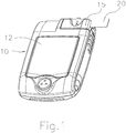
- Fig. 1 shows a perspective view of a measuring meter 10 according to the present invention.
- the measuring meter 10 comprises a housing with a display 12 for display of measurement values.
- the measuring meter 10 includes a slot 15 for insertion of an electrochemical test strip 20.
- the test strip 20 is shown in more detail in Fig. 2A to 2D .
- Fig. 2A shows a top view and the right part of Fig. 2A shows a bottom view of the test strip 20.
- Fig. 2B shows a cross section through the test strip shown in Fig. 2A and 2B .
- Electrodes 21, 22 are mounted in through holes 213 arranged in a recess 210 of the test strip 20.
- the peripheral areas of the electrodes 21, 22 are tightly surrounded by the through holes 213 without a gap being formed.
- the diameter of the through holes 213 is formed slightly smaller than the diameter of the electrodes such that the electrodes are mechanically held in the through holes 213.
- the upper surfaces 211, 212 of the electrodes 21, 22 form a working area of the electrode.
- the lower side 24, 25 of the electrode form output contacts of the test strip. These output contacts may be brought into electrical connection with respective contacts 413, 414 of the sensing meter 10 (see Fig. 4 ).
- a hydrophilic cover 27 with an air hole 28 is arranged such as to cover the recess 210 and such as to form a capillary channel 23.
- the capillary channel 23 defines a reaction zone.
- the reagent comprises in a known manner an enzyme such as a glucose oxidase, a mediator such as a potassium ferrocyanide and some hydrophilic chemical elements.
- the composition of the reagent is known in the art and is not part of the present invention.
- the sensor strip is furthermore provided with a sample inlet 26 for placing a droplet of a liquid sample 29, e.g. a droplet of blood.
- a blood sample 29 When a blood sample 29 is placed onto an opening of the sample inlet 26 (see Fig. 2C ), the droplet is automatically sucked into the capillary channel 23 by capillary action or hydrophilic action.
- Fig. 2C and 2D show the flow of a droplet of blood sample 29.
- the sample When the sample is applied to the inlet 26 of the test strip, it begins to flow through the capillary channel 23 (see Fig. 2C ) until it completely covers the electrodes (see Fig. 2D ). Air contained in the capillary channel may exit through the opening 28.
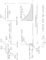
- Fig. 3A shows a method carried out by a measuring meter in accordance with the prior art, e.g. in accordance with the disclosure of US 5,366,609 .
- Fig. 3B to 3C show enlarged views of the consumption current created during sample detection because of application of a voltage.
- a fixed voltage 302 is applied to the electrodes once the sensor strip has been inserted at the time 300 into the measuring meter such as to detect the presence of a test sample during a detection period 301 in the reaction zone.
- a drop of a sample is applied to the sensor strip at the time 308.
- Fig. 3B shows in enlarged form the current flowing between the electrodes when presence of a sample drop will be detected.
- a sample size delay time 314 is applied once a presence of a drop has been detected at the time 316 when the flowing current has reached a drop detection threshold 312.
- the measuring meter In order to continuously verify whether the sample size has become sufficient, the measuring meter thus continuously applies the fixed voltage 302 to the electrodes until a point in time 303 (see Fig. 3A ) after the time 316 when presence of the sample has been detected.
- the amplitude of the flowing current 309 is compared with a sample size threshold 313 at the moment 315 defining the end of the sample size delay time 314. If the amplitude is below the sample size threshold 313, the measuring meter will generate an alarm indicating that insufficient sample is present in the sensor strip. The measuring process will then be stopped.
- the measuring meter continues to the next process step, i.e. to the start of incubation period 305.
- the measuring meter turns off the fixed voltage 302 to a zero value 304.
- mixing and melting of the sample with the reagent is allowed for a certain, predetermined period of time.
- the meter starts a measurement period. For this purpose, a predetermined voltage 307 is applied to the electrodes. The current 310 (see Fig. 3A , lower part) flowing between the electrodes is measured.
- Determination of the concentration of analytes is made on the basis of this so called Cottrell Current.
- the concentration value determined on the basis of the Cottrell Current during a measurement period 306 will be displayed on a display of the meter.
- Fig. 3B an enlarged view of the current flowing at the end of the sample detection period is shown.
- the area below the curve of the current marked as consumption current 309 is equal to the total current flowing until the end of the sample size delay period 314. It equals the number of electrons consumed during this period of time.
- This consumption current is due to the reaction between the reagent and the analyte in the test sample.
- Fig. 3C two different consumption currents 309B and 309C depending on different flow speeds of the sample drop are shown. Different flow speeds of the sample lead to a varying end of the sample detection and thus to a varying consumption period.
- the duration of consumption may vary between 0,04 and 0,3 seconds.
- the sample flow speed may be affected by manufacturers, e.g.
- the blood sample will e.g. flow slowly at low ambient temperature, high HCT or high fat content in the blood.
- the variability of the consumption duration between 0,04 to 0,3 seconds is relatively high as compared to a short total measurement time of 1 second.
- Many current glucose monitors have a 5 second total detection time which includes an incubation and measuring period. The measuring period in such cases is about 1 second only.
- variability may be high for small sample sizes, e.g. used in 1 ⁇ L, 0,5 ⁇ L and 0,3 ⁇ L test strips. Because of current consumption in known measuring meters, measuring errors may be relatively high, especially if small volumes of samples or short detection times are used.
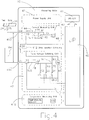
- Fig. 4 shows a schematic representation of a test meter 10 according to the present invention.
- the test meter comprises a microprocessor 40, a display 41, a power supply unit 42, a current measuring unit 43, a temperature measuring unit 410, a strip insertion detecting unit 412 with a switch SW and a pulse voltage switching unit 47. Except from the pulse voltage switching unit 47, these parts and the design of the circuit are known to those skilled in the art.
- the resistance Rf designates the resistance of an electrical conductor through which the current is flowing.
- An analogue to digital converter 46 converts the analogue voltage V 0 to a digital signal which can be input to the microprocessor 40.
- the pulse voltage switching unit 47 is used to apply repeatedly varying voltages to the electrodes.
- the voltage switching unit 47 includes electronic circuits, namely a voltage regulator 49, a voltage divider formed by resistances R1, R2, R3 and switches S2, S3, S4 such as to apply a desired voltage at a point VC1.
- a current buffer 48 having a large current driving capacity is used to output a voltage at the point VC2 equal to the voltage at VC1.
- a control switch S1 is used to connect and disconnect the point VC2 to the contact 414. Thereby, the voltage of point VC2 can be applied to the point VC.
- control lines 417 are exiting the microprocessor 40 such as to control the switches S1, S2, S3, S4, in particular such as to turn the switches on or off.
- the amplitude and duration of the voltage VC at the point 414 can be controlled by switching the switches S1, S2, S3, S4 in a controlled time sequence of turning off/turning on by the microprocessor 40.
- the regulating voltage Ve 49 is applied at point 49 between the ground and contact of the resistance R1.
- the regulating voltage Ve is further connected to the positive input terminal 415 of the current to voltage converter 45.
- the voltage of the negative terminal 416 of the current to voltage converter 45 is adjusted to the same voltage level as the positive input terminal 415 automatically by means of an operational amplifier. Consequently, the output voltage at the point V w is equal to the voltage Ve.
- An electrode working voltage V wc 411 (equal to the difference between V w and V c ) is thus applied between contacts 413, 414 such that it can be electrically connected to the contacts 24, 25 of the test strip 20.
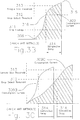
- Fig. 5A shows a first embodiment of a measuring method according to the present invention.
- Mechanical insertion of a test strip is detected at a point 500 in traditional manner.
- the measuring meter applies a repeated pulsed voltage 501 to the electrodes.
- This repeated pulsed voltage 501 is used to detect the presence of a sample during the sample detection period 502.
- a fixed voltage 512 is applied to the electrodes for measuring the Cottrell Current 516. Detection including incubation and measurement lasts for a total detecting time 517. Determination and display of measurement results will be made in a conventional manner thereafter.
- Strip insertion is detected by the strip insertion detection unit 412 (see Fig. 4 ).
- the repeatedly pulsed voltage 501 is switched between predetermined high voltage levels 503 and low voltage levels 504.
- the predefined voltages at the low or high level are controlled by the voltage divider formed by the resistances R1, R2, R3 and the switches S2, S3 and S4 as described hereinabove with respect to Fig. 4 .
- a pulsed voltage 501 including a plurality of voltage pulses is applied to the electrodes. These voltage pulses include a repeated increase and decrease of the applied voltage. At the beginning of a pulse, the voltage applied to the electrodes is rapidly increased to a maximum value. At the end of the pulse, the voltage is quickly decreased at a zero or low value. A time difference T1 separates two subsequent pulses. The duration of each of the pulses is equal to T2.
- the voltage applied to the electrodes is at a level 504 equal or near to zero.
- the switch S1 (see Fig. 4 ) is opened.
- the switch S1 may be closed.
- the purpose of having a pulsed voltage during the sample detection period 502 is to reduce the consumption of current during the sample detection period 502. Only during the active duration T2, the switch S1 is turned on and the predefined voltage 503 is applied to the electrodes.
- Fig. 5A shows the current flowing between the electrodes in the lower part of Fig. 5A .
- Fig. 5B shows an enlarged view of the current flowing during the sample detection period.
- the consumption current 309 of prior art methods as shown in Fig. 3B produced by application of a fixed voltage 302 is indicated in Fig. 5B . Because of the application of a pulsed voltage in accordance with the present invention, the consumption current will be only formed by the area 514, 515 below the current curve during the active durations T2.
- a sample drop is applied.
- the sample is flowing into the test strip in accordance with the description of Fig. 2C and 2D .
- T1 no voltage is applied to the electrodes or only a very low voltage is applied.
- T2 e.g. during the pulse 505 shown in Fig. 5B
- a current 514 is flowing between the electrodes once a sample is present.
- the amplitude of the current is initially less than the sample threshold 513. Consequently, it is considered that not a sufficient amount of sample is present.
- the meter therefore continuous to apply pulsed voltages.
- a first, subsequent inactive period T1 no voltage is applied and the flowing current is reduced to zero after the end of active pulse 505.
- a new pulse 506 is applied.
- the amplitude of the current now is above the sample threshold 513 indicating that sufficient sample is present.
- the meter now stops application of further pulsed voltages and starts the incubation period 507 (see Fig. 5A ).
- the total of consumed current is equal to the sum of the areas below the curve 514 and the curve 515.
- the amount of consumed current (or consumed electrons) is thus highly reduced as compared to the consumption current in prior art methods (which is equal to the surface below the curve 309).
- the optimal selection of the pulse length and cycling time may be determined by experiments.
- the time of a pulse i.e. the active duration T2 may be between 10 ⁇ sec. and 300 ⁇ sec.
- the inactive period T1, i.e. the time delay between subsequent pulses may be between 10 msec. and 50 msec.
- an active duration T2 of 100 ⁇ sec and a inactive time T1 of 20 msec has been turned out to be a good combination.
- the time of the pulses i.e. the active duration T2 is also dependent on the response time of the analogue digital converter 46 (see Fig. 4 ).
- an active time T2 of 100 ⁇ sec. is convenient for conventional A/D converter.
- the selection of the inactive period T1 is made as a compromise between a quick response time for sample presence and low consumption of current.
- the response time of sample presence detection may be twice as fast as prior art methods shown in Fig. 3B (according to which the sample size detection delay time 314 forming only part of the total detection time is 40 msec).
- the consumption of current during the sample detection period can be reduced by 99,5%.
- the consumption current according to prior art methods is unstable because of different flow speeds of different test samples.
- the effect of unstable consumption current can be highly reduced.
- the application of a pulsed voltage during the sample detection period in accordance with the present invention improves precision and accuracy of a measurement, in particular when small test samples are used or when small detection times are used.
- the repeatedly pulsed voltage 508 is applied continuously.
- the fixed voltage 302 is interrupted to a low or zero voltage 304 during the whole incubation period 305 (see Fig. 3A ).
- a repeatedly pulsed voltage 508 is applied in order to periodically allow the reaction of equation (6).
- the mediator in the reduced form M (RED) can be oxidised to the oxidised form M (ox) of the mediator.
- This oxidised form M (ox) will compete with the oxygen by reacting with the reduced form of the glucose oxidase (GOD) in accordance with equation (2) and equation (5).
- GOD glucose oxidase
- the amplitude 509 of the voltage pulses 508 must be selected high enough such as to allow oxidation of the mediator in accordance with equation (6).
- This voltage 509 should be, however, not high enough in order to allow H 2 O 2 to oxidise to oxygen, 2H + and electrons in accordance with equation (3) under normal conditions.
- about 600 mV of electrode working voltage would be used to oxidise H 2 O 2 .
- the reaction according to equation (3) will stop almost completely if the predefined voltage 509 is kept below 250 mV. Consequently, the amplitude 509 is typically around 200 mV.
- a relatively high duty ratio ensures that enough mediator is regenerated during the incubation period.
- a too high duty ratio will consume a too high amount of current during the incubation period and thus will reduce the measuring current during the measuring period 511.
- An optimum duty ratio can be determined by way of experiment.
- a inactive period T3 of about 10 msec. to 300 msec. and a pulse duration T4 of about 10 ⁇ sec. to 1 msec. has shown to be appropriate.
- the duty ratio in this case typically is between 0,01 and 1%.
- the duty ratio may be selected dependent on the type of mediator, the level of the predefined voltage and also of the structure of the electrodes of the test strip.
- Fig. 6A to 6C show three further embodiments in accordance with the present invention.
- a repeatedly pulsed voltage 601 varying between a high level 603 and a low level 604 is applied during the sample detection period 602 after strip insertion 600.
- the pulses applied during this period are substantially identical to the pulses applied in the sample detection period 502 shown with reference to Fig. 5A .
- Consumption of current is reduced.
- a constantly low voltage 606 is applied.
- consumption of current during sample detection period 602 will be reduced.
- a higher voltage 608 is applied.
- Fig. 6B shows a further alternative embodiment. Unlike in Fig. 5A , a fixed voltage 612 is applied after strip insertion at point 610 during the sample detection period 611. A repeatedly pulsed voltage 614 varying between a high level 615 and a low level 616 is applied during the incubation period 613 in a manner similar to the repeatedly pulsed voltage applied in the method explained with reference to Fig. 5A . Therewith, generation of oxygen gas bubbles can be reduced. Measurement is made by applying a voltage 618 during a measurement period 617.
- Fig. 6C shows a third embodiment of the invention.
- a repeatedly pulsed voltage 621 varying between a high voltage state 623 and a low voltage state 624 is applied in a manner similar to the one explained with reference to Fig. 5A .
- a repeatedly pulsed voltage 628 varying between a high state 629 and a low state 630 is applied.
- the pulse times T2, T4 during the sample detection period 622 and the incubation period 627 are different from each other.
- the inactive time T1, T3 and the high state 623, 629 and the voltage levels at the low states 624, 630 are different in the sample detection period 622 and in the incubation period 627. By specifically selecting these parameters, an optimum result in view of current consumption and generation of oxygen bubbles can be achieved. Measurement during a measurement period 631 is made by application of a voltage 632.
- Fig. 7 shows an alternative embodiment of a measuring meter in accordance to the invention.
- the measuring meter 10 has the same units as the one shown in Fig. 4 , in particular a microprocessor 70, a display 71, a power supply unit 72, a current measuring unit 73, a temperature measuring unit 710, a strip insertion detecting unit 712 with a switch SW and a pulse voltage switching unit 79.
- the control switch S1 has been removed between the points VC2 and VC. All other switches S2, S3, S4 are still present.
- Switches SL1, SL2 and Sf are arranged in the current measuring unit 73.
- a current buffer 711 is directly connected to point 714.
- the pulse voltage switching unit 79 is used to switch the amplitude of the predefined voltage at the contact point VC only. To output the desired predefined voltage VC at the point 714, switches S2, S3 and S4 are controlled by the microprocessor 70.
- the current measuring unit 73 comprises a current to voltage converter 74 which is used to convert a current I in a branch 76 flowing between the electrodes 21, 22 (see Fig. 2A to 2D ) to an analogue voltage Vo at a point 77.
- An analogue to digital converter 75 coverts the analogue voltage Vo at point 77 to a digital signal which will be input into the microprocessor 70.
- the current to voltage converter 45 in accordance with Fig. 4 is formed by a feedback resistor Rf and an operational amplifier 45.
- a circuit with three branches connected in parallel is used to provide a feedback connection with the operational amplifier.
- a feedback resistor Rf is connected in series with a switch Sf.
- a resistor RL1 is connected in series with a switch SL1.
- a resistor RL2 is connected in series with a switch SL2.
- the switches SF, SL1 and SL2 are controlled and turned in their on/off state by the microprocessor 70. Thereby, either one of the resistances Rf, RL1 or RL2 may be used for feedback connection with the operational amplifier 74.
- the resistance Rf is activated by closing the switch SF, and the other switches are turned off.
- a working voltage V wc 78 is applied between the points 714 (having the voltage VC) and 713 (having a working voltage V w ) provided.
- the resistors RL1 and RL2 are used during incubation period 507 (see Fig. 5A ) in order to limit the amplitude 518, 519 of the current generated during incubation period 507 (see Fig. 5A ).
- the output voltage Vo is (see above) proportionally increasing with the measuring current I in the branch 76.
- the output value Vo cannot increase to any value.
- the saturation voltage is about 1,2 to 1,8 volt below the value of the positive supply voltage Vcc. If e.g. the positive supply voltage of the operational amplifier Vcc is 5 volt, the saturation voltage will be around 3,8 volt. Because of this limitation, selection of an optimum resistance for the feedback Rf for desired current measuring range will be necessary.
- a resistance Rf of 27 K ⁇ is suitable for a current in the range of between 0 and 100 ⁇ A in a system having a supply voltage Vcc of 5 volt.
- the maximum saturation current Isat Vsat ⁇ Vc / Rf where Vc is the voltage at the point 714 shown in Fig. 7 .
- the saturation current is about 120 ⁇ A.
- a repeatedly pulsed voltage 508 is applied to the electrodes in order to minimise the effect of oxygen bubbles.
- the test sample is completely mixed and melted with the reagent. Consequently, a large pulse current will be produced at each active duration 509.
- the pulse current will be limited by the maximum of the saturation current I SAT explained hereinabove.
- a saturation current 520 (see Fig. 5A ) of 120 ⁇ A flows between the electrodes during each active duration 509 if a 27 K ⁇ resistance is used for Rf. It is not necessary to have higher currents in order to minimise the effect of oxygen gas bubble production.
- the use of limited resistors RL1 or RL2 having 120 K ⁇ and 680 K ⁇ respectively is proposed. These different resistances can be applied for different concentrations of analytes in the testing samples.
- the voltage Vo can be measured by the microprocessor. In answer to a measurement result, either switch SL1 or switch SL2 can be turned on.
- the pulse current amplitude 519 will increase if a resistance Rf of 27 K ⁇ is used.
- the pulse current is limited to a saturation limited pulse current 520 (see Fig. 5A ) if the resistance RL1 (120 K ⁇ ) is used as a feedback resistor, the saturation current will be about 27 ⁇ A. Thus it will reduce current consumption during the incubation time.
Claims (17)
- Verfahren zum Betrieb eines Messgeräts (10) für einen elektrochemischen Teststreifen(20), umfassend- einen Zeitraum (502; 602; 611; 622) zur Detektierung der Anwesenheit der Probe, nach dem eine Probe in der Reaktionszone anwesend ist,- einen Inkubationszeitraum (507; 605, 613, 627), die Zeit, in der das Mischen und Verschmelzen der Probe mit einem Reagenz des Teststreifens möglich ist, und- einen Messzeitraum (306; 511; 607; 617; 631), wobei eine feste Spannung (307; 512; 608; 618; 632) an die Elektroden angelegt wird, um einen Cottrell-Strom (310; 516) zu messen, wobei mindestens während eines von dem Zeitraum der Detektierung der Anwesenheit der Probe (502; 602; 611; 622) und einem Inkubationszeitraum (507; 605, 613, 627) eine Spannung (501, 508; 601; 614; 621, 628) an Elektroden (21, 22) des Teststreifens (20) angelegt wird,wobei die an die Elektroden (21, 22) angelegte Spannung wiederholt als Puls erhöht und abgesenkt wird und die Pulse durch eine Zeitdifferenz (T1, T3) mindestens während eines von
dem Zeitraum der Detektierung der Anwesenheit der Probe (502; 602; 611; 622), wobei ein Strom oberhalb eines Probenschwellenwerts angibt, dass ausreichend Probe vorhanden ist, und
dem Inkubationszeitraum (507; 605, 613, 627) getrennt sind, wobei die Dauer der Pulse (507; 605, 613, 627) 10 bis 300 µs, vorzugsweise 100 µs beträgt und wobei die Zeit zwischen aufeinander folgenden Pulsen 10 bis 50 ms, vorzugsweise 20 ms beträgt. - Verfahren nach Anspruch 1, wobei die wiederholt variierende Spannung (501, 508; 601; 614; 621; 628) in einem regelmäßigen Muster mit einer vorab festgelegten oder vorab festlegbaren Frequenz und mit einem Maximalwert, der während mindestens einer der Zeiträume konstant ist, angelegt wird.
- Verfahren nach Anspruch 2, wobei der Mindestwert zwischen zwei aufeinander folgenden Pulsen 0 Volt ist.
- Verfahren nach Anspruch 2, wobei der Mindestwert der Spannung zwischen zwei aufeinander folgenden Pulsen >0 Volt, jedoch weniger als 0,1 Volt ist.
- Verfahren nach einem der Ansprüche 1 bis 4, wobei der Maximalwert der während des Inkubationszeitraums (507; 605, 613, 627) angelegten Spannung ausreichend hoch ist, um Oxidation der reduzierten Form eines Mediators M(RED) in einem Reagenz eines Teststreifens zu ihrer oxidierten Form M(Ox) zu ermöglichen, jedoch vorzugsweise ausreichend niedrig ist, um Oxidation von H2O2 in dem Reagenz zu vermeiden.
- Verfahren nach einem der Ansprüche 1 bis 5, wobei der Maximalwert der während des Zeitraums der Detektierung der Anwesenheit der Probe (502; 602; 611; 622) an die Elektroden (21, 22) angelegten Spannung ausreichend ist, um einen messbaren Strom zwischen den Elektroden (21, 22) zu erzeugen, wenn eine Probe anwesend ist.
- Verfahren nach Anspruch 1 und 2, wobei die Dauer (T1, T3) zwischen zwei aufeinander folgenden Pulsen durch einen offenen Schaltkreis bewirkt wird.
- Messgerät (10) für einen elektrochemischen Teststreifen (20), umfassend einen Mikroprozessor (40), ein Display (41), eine Strommesseinheit (43) und Mittel (47; 79) zum Anlegen einer Spannung an Elektroden (21, 22) des Teststreifens (20),
wobei die Mittel (47; 79) ausgestaltet sind, um während mindestens einem von
dem Zeitraum der Detektierung der Anwesenheit der Probe (502; 602; 611; 622), in dem das Gerät die Anwesenheit einer Testprobe detektiert und wobei die oberhalb eines Probenschwellenwerts befindliche Amplitude des Stroms angibt, dass ausreichend Probe anwesend ist, und
dem Inkubationszeitraum (507; 605; 613; 627), in dem Mischen und Schmelzen der Probe mit einem Reagenz des Teststreifens möglich ist,
eine wiederholt als Puls ansteigende und absinkende Spannung (501, 508; 601; 614; 621, 628) anzulegen und die Wiederholungen durch eine Zeitdifferenz (T1, T3) zu trennen, wobei die Dauer der Pulse (507; 605, 613, 627) 10 bis 300 µs, vorzugsweise 100 µs beträgt und wobei die Zeit zwischen aufeinander folgenden Pulsen 10 bis 50 ms, vorzugsweise 20 ms beträgt,
und wobei die Mittel (47; 79) zum Anlegen einer festen Spannung (307; 512; 608; 618; 632) an die Elektroden ausgelegt sind, um in einem Messzeitraum einen Cottrell-Strom (310; 516) zu messen. - Gerät nach Anspruch 8, wobei die Mittel (47; 79) ausgestaltet sind zum Anlegen einer Spannung in einem regelmäßigen Muster mit einer vorab festgelegten oder vorab festlegbaren Frequenz.
- Gerät nach Anspruch 9, wobei die Mittel (47; 79) zum Anlegen einer Spannung ausgestaltet sind, um eine Spannung von 0 Volt zwischen aufeinander folgenden Pulsen anzulegen.
- Gerät nach Anspruch 9, wobei die Mittel (47; 79) zum Anlegen einer Spannung ausgestaltet sind, um eine Spannung von >0 Volt, jedoch weniger als 0,1 Volt zwischen aufeinander folgenden Pulsen anzulegen.
- Gerät nach einem der Ansprüche 8 bis 11, wobei die Mittel (47; 79) zum Anlegen einer Spannung während des Inkubationszeitraums (507; 605, 613, 627) ausgestaltet sind, um eine ausreichend hohe Spannung anzulegen, um die reduzierte Form eines Mediators MRED in dem Reagenz eines Teststreifens zu ihrer oxidierten Form Mox zu oxidieren, jedoch vorzugsweise mit einem ausreichend niedrigen Maximalwert, um Oxidation von H2O2 in dem Reagenz zu vermeiden.
- Gerät nach einem der Ansprüche 8 bis 12, wobei die Mittel (47; 79) zum Anlegen einer Spannung ausgestaltet sind, um während des Zeitraums der Detektierung der Anwesenheit der Probe (502; 602; 611; 622) eine Spannung mit einem Maximalwert anzulegen, der ausreicht, um einen messbaren Strom zwischen den Elektroden (21, 22) des Teststreifens zu erzeugen, wenn eine Probe anwesend ist.
- Gerät nach einem der Ansprüche 10 bis 13, wobei die Mittel (47; 79) zum Anlegen einer Spannung ausgestaltet sind, um eine Spannung anzulegen, die aus Pulsen mit einer Dauer (T2; T4) von 10 bis 300 µs, vorzugsweise 100 µs besteht und/oder mit einer Zeit (T1; T3) zwischen aufeinander folgenden Pulsen von 10 bis 50 ms, vorzugsweise 20 ms.
- Gerät nach einem der Ansprüche 8 bis 14, wobei das Gerät mit Mitteln zum Begrenzen des Stromflusses zwischen derartigen Elektroden während eines Inkubationszeitraums (507; 605, 613, 627) ausgestattet ist.
- Gerät nach Anspruch 15, wobei die Mittel zum Begrenzen des Stroms durch mindestens zwei Widerstände gebildet sind, die selektiv mit einem Eingang eines Operationsverstärkers eines Strom-zu-Spannung-Wandlers verbunden werden können.
- Verfahren nach einem der Ansprüche 1 bis 7, das den weiteren Schritt des Begrenzens des zwischen Elektroden eines Teststreifens während eines Inkubationszeitraums fließenden Stroms umfasst.
Priority Applications (4)
| Application Number | Priority Date | Filing Date | Title |
|---|---|---|---|
| EP06114494.5A EP1860432B1 (de) | 2006-05-24 | 2006-05-24 | Verfahren zum Betrieb eines Messgeräts und Messgerät |
| TW096114703A TWI334026B (en) | 2006-05-24 | 2007-04-25 | Method for operating a measuring meter and measuring meter |
| US11/799,855 US8236165B2 (en) | 2006-05-24 | 2007-05-02 | Method for operating measuring meter and measuring meter |
| CN2007101039102A CN101078719B (zh) | 2006-05-24 | 2007-05-15 | 测量仪操作方法及测量仪 |
Applications Claiming Priority (1)
| Application Number | Priority Date | Filing Date | Title |
|---|---|---|---|
| EP06114494.5A EP1860432B1 (de) | 2006-05-24 | 2006-05-24 | Verfahren zum Betrieb eines Messgeräts und Messgerät |
Publications (2)
| Publication Number | Publication Date |
|---|---|
| EP1860432A1 EP1860432A1 (de) | 2007-11-28 |
| EP1860432B1 true EP1860432B1 (de) | 2017-12-13 |
Family
ID=37726739
Family Applications (1)
| Application Number | Title | Priority Date | Filing Date |
|---|---|---|---|
| EP06114494.5A Active EP1860432B1 (de) | 2006-05-24 | 2006-05-24 | Verfahren zum Betrieb eines Messgeräts und Messgerät |
Country Status (4)
| Country | Link |
|---|---|
| US (1) | US8236165B2 (de) |
| EP (1) | EP1860432B1 (de) |
| CN (1) | CN101078719B (de) |
| TW (1) | TWI334026B (de) |
Families Citing this family (16)
| Publication number | Priority date | Publication date | Assignee | Title |
|---|---|---|---|---|
| DE102006043718B4 (de) * | 2006-09-18 | 2014-12-31 | Alexander Adlassnig | Bestimmung von Wasserstoffperoxidkonzentrationen |
| US8551320B2 (en) * | 2008-06-09 | 2013-10-08 | Lifescan, Inc. | System and method for measuring an analyte in a sample |
| TWI388823B (zh) * | 2009-04-09 | 2013-03-11 | Bionime Corp | 一種判斷樣品佈滿狀況的偵測方法 |
| CN106053585A (zh) * | 2009-05-12 | 2016-10-26 | 华广生技股份有限公司 | 一种判断样品布满状况的侦测方法 |
| US8501093B2 (en) * | 2009-06-11 | 2013-08-06 | Roche Diagnostics Operations, Inc. | Portable handheld medical diagnostic devices with color-changing indicatior |
| WO2012164271A1 (en) * | 2011-05-27 | 2012-12-06 | Lifescan Scotland Limited | Peak offset correction for analyte test strip |
| TWI427291B (zh) | 2011-07-06 | 2014-02-21 | Bionime Corp | 使用電化學感測片測量樣本的方法 |
| TWI547687B (zh) * | 2012-06-13 | 2016-09-01 | 達爾生技股份有限公司 | 血液樣本之血糖值的校正方法及其校正系統 |
| CN102788825B (zh) * | 2012-07-29 | 2014-07-30 | 江苏大学 | 一种血糖检测方法和血糖仪 |
| TW201430342A (zh) * | 2013-01-28 | 2014-08-01 | Actherm Inc | 檢測試片之檢測裝置及檢測方法 |
| KR102540664B1 (ko) * | 2015-11-03 | 2023-06-08 | 삼성전자주식회사 | 바이오 센서 및 그의 센싱 방법 |
| AU2018373137A1 (en) | 2017-11-21 | 2020-07-02 | MX3 Diagnostics, Inc. | Saliva testing system |
| TWI656342B (zh) * | 2018-03-13 | 2019-04-11 | 福永生物科技股份有限公司 | 判斷樣品分佈狀況的電化學感測方法 |
| CN113853160A (zh) * | 2019-06-26 | 2021-12-28 | 聚合物技术系统公司 | 用于降低电化学生物传感器中氧张力的系统和方法 |
| US11701036B2 (en) | 2019-07-10 | 2023-07-18 | MX3 Diagnostics, Inc. | Saliva test strip and method |
| EP4097470A4 (de) * | 2020-01-30 | 2024-03-06 | Mx3 Diagnostics Inc | Bewertung biologischer flüssigkeitsproben |
Citations (1)
| Publication number | Priority date | Publication date | Assignee | Title |
|---|---|---|---|---|
| US20040260511A1 (en) * | 2003-06-20 | 2004-12-23 | Burke David W. | System and method for determining an abused sensor during analyte measurement |
Family Cites Families (18)
| Publication number | Priority date | Publication date | Assignee | Title |
|---|---|---|---|---|
| US4897162A (en) * | 1986-11-14 | 1990-01-30 | The Cleveland Clinic Foundation | Pulse voltammetry |
| US5108564A (en) * | 1988-03-15 | 1992-04-28 | Tall Oak Ventures | Method and apparatus for amperometric diagnostic analysis |
| US5766934A (en) * | 1989-03-13 | 1998-06-16 | Guiseppi-Elie; Anthony | Chemical and biological sensors having electroactive polymer thin films attached to microfabricated devices and possessing immobilized indicator moieties |
| JPH0820412B2 (ja) * | 1990-07-20 | 1996-03-04 | 松下電器産業株式会社 | 使い捨てセンサを用いた定量分析方法、及び装置 |
| US5260663A (en) * | 1992-07-14 | 1993-11-09 | Anatel Corporation | Methods and circuits for measuring the conductivity of solutions |
| US5366609A (en) * | 1993-06-08 | 1994-11-22 | Boehringer Mannheim Corporation | Biosensing meter with pluggable memory key |
| US5620579A (en) * | 1995-05-05 | 1997-04-15 | Bayer Corporation | Apparatus for reduction of bias in amperometric sensors |
| WO1998058250A2 (en) * | 1997-06-16 | 1998-12-23 | Elan Corporation, Plc | Methods of calibrating and testing a sensor for in vivo measurement of an analyte and devices for use in such methods |
| JP3859239B2 (ja) * | 1997-07-22 | 2006-12-20 | アークレイ株式会社 | 濃度測定器、該濃度測定器用試験片、バイオセンサシステム、及び上記試験片の端子形成方法 |
| GB9916522D0 (en) * | 1999-07-15 | 1999-09-15 | Univ Manchester | Polymeric compositions and sensor devices |
| DE60037592T2 (de) * | 1999-09-20 | 2009-01-22 | Roche Diagnostics Gmbh | Methode zur Messung eines Analyten mit Hilfe eines elektrochemischen Biosensors, der durch Anlegen eines Potentials abgeschaltet werden kann |
| KR100340173B1 (ko) | 2000-03-22 | 2002-06-12 | 이동준 | 전기화학적 바이오센서 측정기 |
| US6946299B2 (en) * | 2002-04-25 | 2005-09-20 | Home Diagnostics, Inc. | Systems and methods for blood glucose sensing |
| CN100451637C (zh) * | 2003-01-24 | 2009-01-14 | 黄椿木 | 电化学式传感器及其制造方法 |
| CN100342230C (zh) * | 2003-05-07 | 2007-10-10 | 黄椿木 | 抛弃式电化学式感测试片的结构及其制作方法 |
| CN100392389C (zh) * | 2003-11-07 | 2008-06-04 | 华广生技股份有限公司 | 一种电化感测试片 |
| CN1614404A (zh) * | 2003-11-07 | 2005-05-11 | 华广生技股份有限公司 | 电化学式感测装置 |
| US7344626B2 (en) * | 2005-04-15 | 2008-03-18 | Agamatrix, Inc. | Method and apparatus for detection of abnormal traces during electrochemical analyte detection |
-
2006
- 2006-05-24 EP EP06114494.5A patent/EP1860432B1/de active Active
-
2007
- 2007-04-25 TW TW096114703A patent/TWI334026B/zh active
- 2007-05-02 US US11/799,855 patent/US8236165B2/en active Active
- 2007-05-15 CN CN2007101039102A patent/CN101078719B/zh active Active
Patent Citations (1)
| Publication number | Priority date | Publication date | Assignee | Title |
|---|---|---|---|---|
| US20040260511A1 (en) * | 2003-06-20 | 2004-12-23 | Burke David W. | System and method for determining an abused sensor during analyte measurement |
Also Published As
| Publication number | Publication date |
|---|---|
| US20070272564A1 (en) | 2007-11-29 |
| TW200743797A (en) | 2007-12-01 |
| CN101078719B (zh) | 2013-02-20 |
| CN101078719A (zh) | 2007-11-28 |
| US8236165B2 (en) | 2012-08-07 |
| TWI334026B (en) | 2010-12-01 |
| EP1860432A1 (de) | 2007-11-28 |
Similar Documents
| Publication | Publication Date | Title |
|---|---|---|
| EP1860432B1 (de) | Verfahren zum Betrieb eines Messgeräts und Messgerät | |
| US7491310B2 (en) | Concentration measuring method and concentration measuring apparatus | |
| EP2437056B1 (de) | Verfahren zur Bestimmung einer substantiell unabhängigen Hämatokritanalytkonzentration | |
| EP3364187B1 (de) | Verfahren zur quantifizierung eines substrats | |
| KR101289757B1 (ko) | 전기화학적 스트립에서의 부분적인 채워짐의 판별 | |
| US6475360B1 (en) | Heated electrochemical cell | |
| US9234862B2 (en) | Analyte determination method and analyte meter | |
| EP1504252B1 (de) | Teststreifen zur Blutglukosebestimmung und Verfahren zur Herstellung desselben. | |
| EP0882226B1 (de) | Elektrochemisches verfahren | |
| AU2005207939B2 (en) | Systems and methods for blood glucose sensing | |
| EP2149792B1 (de) | Probenanalyseverfahren | |
| US20030079987A1 (en) | Heated electrochemical cell | |
| EP2589960A1 (de) | Verfahren und Vorrichtung zur Prüfen elektrochemischer Eigenschaften | |
| EP2080022B1 (de) | Verfahren zur bestimmung einer analytkonzentration mit verwendung von signalprozessierungsalgorithmen | |
| WO2005100968A1 (ja) | 分析装置 | |
| KR20080003419A (ko) | 전기화학적 분석대상물 검출 동안에 비정상적인 경로의검출을 위한 방법 및 장치 | |
| JPWO2007026683A1 (ja) | 試料供給状態の検出方法および分析用具 | |
| US9816957B2 (en) | Blood component measuring device, method for measuring blood component, and bio-sensor | |
| KR20120099452A (ko) | 바이오센서용 언더필 인식 시스템 | |
| US8702960B2 (en) | Method for operating a measurement for a sample on an electrochemical test strip | |
| KR101058754B1 (ko) | 생체 시료 정량 측정 방법 및 생체 시료 정량 측정 시스템 | |
| AU2011202737B2 (en) | Determination of partial fill in electrochemical strips | |
| AU779350B2 (en) | Heated electrochemical cell | |
| AU2013204819A1 (en) | Method and apparatus for assay of electrochemical properties | |
| MXPA06008846A (en) | Electrochemical biosensor |
Legal Events
| Date | Code | Title | Description |
|---|---|---|---|
| PUAI | Public reference made under article 153(3) epc to a published international application that has entered the european phase |
Free format text: ORIGINAL CODE: 0009012 |
|
| AK | Designated contracting states |
Kind code of ref document: A1 Designated state(s): AT BE BG CH CY CZ DE DK EE ES FI FR GB GR HU IE IS IT LI LT LU LV MC NL PL PT RO SE SI SK TR |
|
| AX | Request for extension of the european patent |
Extension state: AL BA HR MK YU |
|
| 17P | Request for examination filed |
Effective date: 20080503 |
|
| 17Q | First examination report despatched |
Effective date: 20080529 |
|
| AKX | Designation fees paid |
Designated state(s): AT BE BG CH CY CZ DE DK EE ES FI FR GB GR HU IE IS IT LI LT LU LV MC NL PL PT RO SE SI SK TR |
|
| AXX | Extension fees paid |
Extension state: MK Payment date: 20080503 Extension state: BA Payment date: 20080503 Extension state: HR Payment date: 20080503 Extension state: AL Payment date: 20080503 Extension state: YU Payment date: 20080503 |
|
| GRAP | Despatch of communication of intention to grant a patent |
Free format text: ORIGINAL CODE: EPIDOSNIGR1 |
|
| INTG | Intention to grant announced |
Effective date: 20151204 |
|
| GRAS | Grant fee paid |
Free format text: ORIGINAL CODE: EPIDOSNIGR3 |
|
| GRAP | Despatch of communication of intention to grant a patent |
Free format text: ORIGINAL CODE: EPIDOSNIGR1 |
|
| INTG | Intention to grant announced |
Effective date: 20160502 |
|
| GRAS | Grant fee paid |
Free format text: ORIGINAL CODE: EPIDOSNIGR3 |
|
| GRAA | (expected) grant |
Free format text: ORIGINAL CODE: 0009210 |
|
| AK | Designated contracting states |
Kind code of ref document: B1 Designated state(s): AT BE BG CH CY CZ DE DK EE ES FI FR GB GR HU IE IS IT LI LT LU LV MC NL PL PT RO SE SI SK TR |
|
| AX | Request for extension of the european patent |
Extension state: AL BA HR MK YU |
|
| REG | Reference to a national code |
Ref country code: GB Ref legal event code: FG4D |
|
| REG | Reference to a national code |
Ref country code: AT Ref legal event code: REF Ref document number: 954879 Country of ref document: AT Kind code of ref document: T Effective date: 20171215 Ref country code: CH Ref legal event code: EP |
|
| REG | Reference to a national code |
Ref country code: IE Ref legal event code: FG4D |
|
| REG | Reference to a national code |
Ref country code: DE Ref legal event code: R096 Ref document number: 602006054315 Country of ref document: DE |
|
| REG | Reference to a national code |
Ref country code: NL Ref legal event code: MP Effective date: 20171213 |
|
| REG | Reference to a national code |
Ref country code: LT Ref legal event code: MG4D |
|
| PG25 | Lapsed in a contracting state [announced via postgrant information from national office to epo] |
Ref country code: SE Free format text: LAPSE BECAUSE OF FAILURE TO SUBMIT A TRANSLATION OF THE DESCRIPTION OR TO PAY THE FEE WITHIN THE PRESCRIBED TIME-LIMIT Effective date: 20171213 Ref country code: LT Free format text: LAPSE BECAUSE OF FAILURE TO SUBMIT A TRANSLATION OF THE DESCRIPTION OR TO PAY THE FEE WITHIN THE PRESCRIBED TIME-LIMIT Effective date: 20171213 Ref country code: FI Free format text: LAPSE BECAUSE OF FAILURE TO SUBMIT A TRANSLATION OF THE DESCRIPTION OR TO PAY THE FEE WITHIN THE PRESCRIBED TIME-LIMIT Effective date: 20171213 |
|
| REG | Reference to a national code |
Ref country code: AT Ref legal event code: MK05 Ref document number: 954879 Country of ref document: AT Kind code of ref document: T Effective date: 20171213 |
|
| PG25 | Lapsed in a contracting state [announced via postgrant information from national office to epo] |
Ref country code: BG Free format text: LAPSE BECAUSE OF FAILURE TO SUBMIT A TRANSLATION OF THE DESCRIPTION OR TO PAY THE FEE WITHIN THE PRESCRIBED TIME-LIMIT Effective date: 20180313 Ref country code: LV Free format text: LAPSE BECAUSE OF FAILURE TO SUBMIT A TRANSLATION OF THE DESCRIPTION OR TO PAY THE FEE WITHIN THE PRESCRIBED TIME-LIMIT Effective date: 20171213 Ref country code: GR Free format text: LAPSE BECAUSE OF FAILURE TO SUBMIT A TRANSLATION OF THE DESCRIPTION OR TO PAY THE FEE WITHIN THE PRESCRIBED TIME-LIMIT Effective date: 20180314 |
|
| PG25 | Lapsed in a contracting state [announced via postgrant information from national office to epo] |
Ref country code: NL Free format text: LAPSE BECAUSE OF FAILURE TO SUBMIT A TRANSLATION OF THE DESCRIPTION OR TO PAY THE FEE WITHIN THE PRESCRIBED TIME-LIMIT Effective date: 20171213 |
|
| PG25 | Lapsed in a contracting state [announced via postgrant information from national office to epo] |
Ref country code: ES Free format text: LAPSE BECAUSE OF FAILURE TO SUBMIT A TRANSLATION OF THE DESCRIPTION OR TO PAY THE FEE WITHIN THE PRESCRIBED TIME-LIMIT Effective date: 20171213 Ref country code: EE Free format text: LAPSE BECAUSE OF FAILURE TO SUBMIT A TRANSLATION OF THE DESCRIPTION OR TO PAY THE FEE WITHIN THE PRESCRIBED TIME-LIMIT Effective date: 20171213 Ref country code: CY Free format text: LAPSE BECAUSE OF FAILURE TO SUBMIT A TRANSLATION OF THE DESCRIPTION OR TO PAY THE FEE WITHIN THE PRESCRIBED TIME-LIMIT Effective date: 20171213 Ref country code: SK Free format text: LAPSE BECAUSE OF FAILURE TO SUBMIT A TRANSLATION OF THE DESCRIPTION OR TO PAY THE FEE WITHIN THE PRESCRIBED TIME-LIMIT Effective date: 20171213 Ref country code: CZ Free format text: LAPSE BECAUSE OF FAILURE TO SUBMIT A TRANSLATION OF THE DESCRIPTION OR TO PAY THE FEE WITHIN THE PRESCRIBED TIME-LIMIT Effective date: 20171213 |
|
| PG25 | Lapsed in a contracting state [announced via postgrant information from national office to epo] |
Ref country code: IT Free format text: LAPSE BECAUSE OF FAILURE TO SUBMIT A TRANSLATION OF THE DESCRIPTION OR TO PAY THE FEE WITHIN THE PRESCRIBED TIME-LIMIT Effective date: 20171213 Ref country code: AT Free format text: LAPSE BECAUSE OF FAILURE TO SUBMIT A TRANSLATION OF THE DESCRIPTION OR TO PAY THE FEE WITHIN THE PRESCRIBED TIME-LIMIT Effective date: 20171213 Ref country code: IS Free format text: LAPSE BECAUSE OF FAILURE TO SUBMIT A TRANSLATION OF THE DESCRIPTION OR TO PAY THE FEE WITHIN THE PRESCRIBED TIME-LIMIT Effective date: 20180413 Ref country code: RO Free format text: LAPSE BECAUSE OF FAILURE TO SUBMIT A TRANSLATION OF THE DESCRIPTION OR TO PAY THE FEE WITHIN THE PRESCRIBED TIME-LIMIT Effective date: 20171213 Ref country code: PL Free format text: LAPSE BECAUSE OF FAILURE TO SUBMIT A TRANSLATION OF THE DESCRIPTION OR TO PAY THE FEE WITHIN THE PRESCRIBED TIME-LIMIT Effective date: 20171213 |
|
| REG | Reference to a national code |
Ref country code: DE Ref legal event code: R097 Ref document number: 602006054315 Country of ref document: DE |
|
| PLBE | No opposition filed within time limit |
Free format text: ORIGINAL CODE: 0009261 |
|
| STAA | Information on the status of an ep patent application or granted ep patent |
Free format text: STATUS: NO OPPOSITION FILED WITHIN TIME LIMIT |
|
| 26N | No opposition filed |
Effective date: 20180914 |
|
| PG25 | Lapsed in a contracting state [announced via postgrant information from national office to epo] |
Ref country code: DK Free format text: LAPSE BECAUSE OF FAILURE TO SUBMIT A TRANSLATION OF THE DESCRIPTION OR TO PAY THE FEE WITHIN THE PRESCRIBED TIME-LIMIT Effective date: 20171213 |
|
| REG | Reference to a national code |
Ref country code: CH Ref legal event code: PL |
|
| GBPC | Gb: european patent ceased through non-payment of renewal fee |
Effective date: 20180524 |
|
| REG | Reference to a national code |
Ref country code: BE Ref legal event code: MM Effective date: 20180531 |
|
| PG25 | Lapsed in a contracting state [announced via postgrant information from national office to epo] |
Ref country code: MC Free format text: LAPSE BECAUSE OF FAILURE TO SUBMIT A TRANSLATION OF THE DESCRIPTION OR TO PAY THE FEE WITHIN THE PRESCRIBED TIME-LIMIT Effective date: 20171213 |
|
| REG | Reference to a national code |
Ref country code: IE Ref legal event code: MM4A |
|
| PG25 | Lapsed in a contracting state [announced via postgrant information from national office to epo] |
Ref country code: CH Free format text: LAPSE BECAUSE OF NON-PAYMENT OF DUE FEES Effective date: 20180531 Ref country code: SI Free format text: LAPSE BECAUSE OF FAILURE TO SUBMIT A TRANSLATION OF THE DESCRIPTION OR TO PAY THE FEE WITHIN THE PRESCRIBED TIME-LIMIT Effective date: 20171213 Ref country code: LI Free format text: LAPSE BECAUSE OF NON-PAYMENT OF DUE FEES Effective date: 20180531 |
|
| PG25 | Lapsed in a contracting state [announced via postgrant information from national office to epo] |
Ref country code: LU Free format text: LAPSE BECAUSE OF NON-PAYMENT OF DUE FEES Effective date: 20180524 |
|
| PG25 | Lapsed in a contracting state [announced via postgrant information from national office to epo] |
Ref country code: GB Free format text: LAPSE BECAUSE OF NON-PAYMENT OF DUE FEES Effective date: 20180524 Ref country code: IE Free format text: LAPSE BECAUSE OF NON-PAYMENT OF DUE FEES Effective date: 20180524 Ref country code: FR Free format text: LAPSE BECAUSE OF NON-PAYMENT OF DUE FEES Effective date: 20180531 |
|
| PG25 | Lapsed in a contracting state [announced via postgrant information from national office to epo] |
Ref country code: BE Free format text: LAPSE BECAUSE OF NON-PAYMENT OF DUE FEES Effective date: 20180531 |
|
| PG25 | Lapsed in a contracting state [announced via postgrant information from national office to epo] |
Ref country code: TR Free format text: LAPSE BECAUSE OF FAILURE TO SUBMIT A TRANSLATION OF THE DESCRIPTION OR TO PAY THE FEE WITHIN THE PRESCRIBED TIME-LIMIT Effective date: 20171213 |
|
| PG25 | Lapsed in a contracting state [announced via postgrant information from national office to epo] |
Ref country code: HU Free format text: LAPSE BECAUSE OF FAILURE TO SUBMIT A TRANSLATION OF THE DESCRIPTION OR TO PAY THE FEE WITHIN THE PRESCRIBED TIME-LIMIT; INVALID AB INITIO Effective date: 20060524 Ref country code: PT Free format text: LAPSE BECAUSE OF FAILURE TO SUBMIT A TRANSLATION OF THE DESCRIPTION OR TO PAY THE FEE WITHIN THE PRESCRIBED TIME-LIMIT Effective date: 20171213 |
|
| PGFP | Annual fee paid to national office [announced via postgrant information from national office to epo] |
Ref country code: DE Payment date: 20220629 Year of fee payment: 18 |