EP2238947B2 - Instrument pour le déploiement in situ de prothèses valvulaires cardiaques - Google Patents
Instrument pour le déploiement in situ de prothèses valvulaires cardiaques Download PDFInfo
- Publication number
- EP2238947B2 EP2238947B2 EP10155332.9A EP10155332A EP2238947B2 EP 2238947 B2 EP2238947 B2 EP 2238947B2 EP 10155332 A EP10155332 A EP 10155332A EP 2238947 B2 EP2238947 B2 EP 2238947B2
- Authority
- EP
- European Patent Office
- Prior art keywords
- annular
- deployment
- radially
- prosthesis
- inflow
- Prior art date
- Legal status (The legal status is an assumption and is not a legal conclusion. Google has not performed a legal analysis and makes no representation as to the accuracy of the status listed.)
- Active
Links
- 210000003709 heart valve Anatomy 0.000 title claims description 29
- 238000011065 in-situ storage Methods 0.000 title description 4
- 230000015572 biosynthetic process Effects 0.000 claims description 14
- 238000005755 formation reaction Methods 0.000 claims description 14
- 230000033001 locomotion Effects 0.000 claims description 14
- 210000001765 aortic valve Anatomy 0.000 claims description 11
- 210000002435 tendon Anatomy 0.000 claims description 11
- 230000017531 blood circulation Effects 0.000 claims description 8
- 238000004873 anchoring Methods 0.000 claims description 7
- 239000000463 material Substances 0.000 claims description 7
- 239000008280 blood Substances 0.000 claims description 6
- 238000006073 displacement reaction Methods 0.000 claims description 5
- 210000004369 blood Anatomy 0.000 claims description 4
- 239000002783 friction material Substances 0.000 claims description 2
- 230000000452 restraining effect Effects 0.000 claims description 2
- 238000002513 implantation Methods 0.000 description 32
- 238000000034 method Methods 0.000 description 32
- 238000013459 approach Methods 0.000 description 8
- 210000005240 left ventricle Anatomy 0.000 description 4
- 230000009471 action Effects 0.000 description 3
- 230000000694 effects Effects 0.000 description 3
- 239000007943 implant Substances 0.000 description 3
- 210000000709 aorta Anatomy 0.000 description 2
- 239000012530 fluid Substances 0.000 description 2
- 230000008569 process Effects 0.000 description 2
- 239000000243 solution Substances 0.000 description 2
- 210000000115 thoracic cavity Anatomy 0.000 description 2
- 210000005166 vasculature Anatomy 0.000 description 2
- 206010016275 Fear Diseases 0.000 description 1
- 229920006362 Teflon® Polymers 0.000 description 1
- 210000002376 aorta thoracic Anatomy 0.000 description 1
- 230000001174 ascending effect Effects 0.000 description 1
- 230000008901 benefit Effects 0.000 description 1
- 230000005540 biological transmission Effects 0.000 description 1
- 230000004087 circulation Effects 0.000 description 1
- 239000011248 coating agent Substances 0.000 description 1
- 238000000576 coating method Methods 0.000 description 1
- 230000000295 complement effect Effects 0.000 description 1
- 239000000470 constituent Substances 0.000 description 1
- 238000010276 construction Methods 0.000 description 1
- 239000007799 cork Substances 0.000 description 1
- 238000002224 dissection Methods 0.000 description 1
- 210000001105 femoral artery Anatomy 0.000 description 1
- 230000000977 initiatory effect Effects 0.000 description 1
- 238000002347 injection Methods 0.000 description 1
- 239000007924 injection Substances 0.000 description 1
- 238000003780 insertion Methods 0.000 description 1
- 230000037431 insertion Effects 0.000 description 1
- 230000009191 jumping Effects 0.000 description 1
- 230000000670 limiting effect Effects 0.000 description 1
- 230000007246 mechanism Effects 0.000 description 1
- 238000002406 microsurgery Methods 0.000 description 1
- 238000012986 modification Methods 0.000 description 1
- 230000004048 modification Effects 0.000 description 1
- HLXZNVUGXRDIFK-UHFFFAOYSA-N nickel titanium Chemical compound [Ti].[Ti].[Ti].[Ti].[Ti].[Ti].[Ti].[Ti].[Ti].[Ti].[Ti].[Ni].[Ni].[Ni].[Ni].[Ni].[Ni].[Ni].[Ni].[Ni].[Ni].[Ni].[Ni].[Ni].[Ni] HLXZNVUGXRDIFK-UHFFFAOYSA-N 0.000 description 1
- 229910001000 nickel titanium Inorganic materials 0.000 description 1
- 230000036961 partial effect Effects 0.000 description 1
- 239000004810 polytetrafluoroethylene Substances 0.000 description 1
- 229920001343 polytetrafluoroethylene Polymers 0.000 description 1
- 230000008092 positive effect Effects 0.000 description 1
- 230000001681 protective effect Effects 0.000 description 1
- 210000003102 pulmonary valve Anatomy 0.000 description 1
- 238000011084 recovery Methods 0.000 description 1
- 230000000717 retained effect Effects 0.000 description 1
- 230000002441 reversible effect Effects 0.000 description 1
- 210000003291 sinus of valsalva Anatomy 0.000 description 1
- 238000006467 substitution reaction Methods 0.000 description 1
- 238000001356 surgical procedure Methods 0.000 description 1
- MEYZYGMYMLNUHJ-UHFFFAOYSA-N tunicamycin Natural products CC(C)CCCCCCCCCC=CC(=O)NC1C(O)C(O)C(CC(O)C2OC(C(O)C2O)N3C=CC(=O)NC3=O)OC1OC4OC(CO)C(O)C(O)C4NC(=O)C MEYZYGMYMLNUHJ-UHFFFAOYSA-N 0.000 description 1
- 238000011144 upstream manufacturing Methods 0.000 description 1
- 230000000007 visual effect Effects 0.000 description 1
Images


Classifications
-
- A—HUMAN NECESSITIES
- A61—MEDICAL OR VETERINARY SCIENCE; HYGIENE
- A61F—FILTERS IMPLANTABLE INTO BLOOD VESSELS; PROSTHESES; DEVICES PROVIDING PATENCY TO, OR PREVENTING COLLAPSING OF, TUBULAR STRUCTURES OF THE BODY, e.g. STENTS; ORTHOPAEDIC, NURSING OR CONTRACEPTIVE DEVICES; FOMENTATION; TREATMENT OR PROTECTION OF EYES OR EARS; BANDAGES, DRESSINGS OR ABSORBENT PADS; FIRST-AID KITS
- A61F2/00—Filters implantable into blood vessels; Prostheses, i.e. artificial substitutes or replacements for parts of the body; Appliances for connecting them with the body; Devices providing patency to, or preventing collapsing of, tubular structures of the body, e.g. stents
- A61F2/02—Prostheses implantable into the body
- A61F2/24—Heart valves ; Vascular valves, e.g. venous valves; Heart implants, e.g. passive devices for improving the function of the native valve or the heart muscle; Transmyocardial revascularisation [TMR] devices; Valves implantable in the body
- A61F2/2427—Devices for manipulating or deploying heart valves during implantation
- A61F2/2436—Deployment by retracting a sheath
-
- A—HUMAN NECESSITIES
- A61—MEDICAL OR VETERINARY SCIENCE; HYGIENE
- A61F—FILTERS IMPLANTABLE INTO BLOOD VESSELS; PROSTHESES; DEVICES PROVIDING PATENCY TO, OR PREVENTING COLLAPSING OF, TUBULAR STRUCTURES OF THE BODY, e.g. STENTS; ORTHOPAEDIC, NURSING OR CONTRACEPTIVE DEVICES; FOMENTATION; TREATMENT OR PROTECTION OF EYES OR EARS; BANDAGES, DRESSINGS OR ABSORBENT PADS; FIRST-AID KITS
- A61F2/00—Filters implantable into blood vessels; Prostheses, i.e. artificial substitutes or replacements for parts of the body; Appliances for connecting them with the body; Devices providing patency to, or preventing collapsing of, tubular structures of the body, e.g. stents
- A61F2/02—Prostheses implantable into the body
- A61F2/24—Heart valves ; Vascular valves, e.g. venous valves; Heart implants, e.g. passive devices for improving the function of the native valve or the heart muscle; Transmyocardial revascularisation [TMR] devices; Valves implantable in the body
- A61F2/2427—Devices for manipulating or deploying heart valves during implantation
- A61F2/243—Deployment by mechanical expansion
- A61F2/2433—Deployment by mechanical expansion using balloon catheter
-
- A—HUMAN NECESSITIES
- A61—MEDICAL OR VETERINARY SCIENCE; HYGIENE
- A61F—FILTERS IMPLANTABLE INTO BLOOD VESSELS; PROSTHESES; DEVICES PROVIDING PATENCY TO, OR PREVENTING COLLAPSING OF, TUBULAR STRUCTURES OF THE BODY, e.g. STENTS; ORTHOPAEDIC, NURSING OR CONTRACEPTIVE DEVICES; FOMENTATION; TREATMENT OR PROTECTION OF EYES OR EARS; BANDAGES, DRESSINGS OR ABSORBENT PADS; FIRST-AID KITS
- A61F2/00—Filters implantable into blood vessels; Prostheses, i.e. artificial substitutes or replacements for parts of the body; Appliances for connecting them with the body; Devices providing patency to, or preventing collapsing of, tubular structures of the body, e.g. stents
- A61F2/95—Instruments specially adapted for placement or removal of stents or stent-grafts
- A61F2/962—Instruments specially adapted for placement or removal of stents or stent-grafts having an outer sleeve
- A61F2/97—Instruments specially adapted for placement or removal of stents or stent-grafts having an outer sleeve the outer sleeve being splittable
-
- A—HUMAN NECESSITIES
- A61—MEDICAL OR VETERINARY SCIENCE; HYGIENE
- A61F—FILTERS IMPLANTABLE INTO BLOOD VESSELS; PROSTHESES; DEVICES PROVIDING PATENCY TO, OR PREVENTING COLLAPSING OF, TUBULAR STRUCTURES OF THE BODY, e.g. STENTS; ORTHOPAEDIC, NURSING OR CONTRACEPTIVE DEVICES; FOMENTATION; TREATMENT OR PROTECTION OF EYES OR EARS; BANDAGES, DRESSINGS OR ABSORBENT PADS; FIRST-AID KITS
- A61F2/00—Filters implantable into blood vessels; Prostheses, i.e. artificial substitutes or replacements for parts of the body; Appliances for connecting them with the body; Devices providing patency to, or preventing collapsing of, tubular structures of the body, e.g. stents
- A61F2/02—Prostheses implantable into the body
- A61F2/24—Heart valves ; Vascular valves, e.g. venous valves; Heart implants, e.g. passive devices for improving the function of the native valve or the heart muscle; Transmyocardial revascularisation [TMR] devices; Valves implantable in the body
- A61F2/2412—Heart valves ; Vascular valves, e.g. venous valves; Heart implants, e.g. passive devices for improving the function of the native valve or the heart muscle; Transmyocardial revascularisation [TMR] devices; Valves implantable in the body with soft flexible valve members, e.g. tissue valves shaped like natural valves
- A61F2/2418—Scaffolds therefor, e.g. support stents
-
- A—HUMAN NECESSITIES
- A61—MEDICAL OR VETERINARY SCIENCE; HYGIENE
- A61F—FILTERS IMPLANTABLE INTO BLOOD VESSELS; PROSTHESES; DEVICES PROVIDING PATENCY TO, OR PREVENTING COLLAPSING OF, TUBULAR STRUCTURES OF THE BODY, e.g. STENTS; ORTHOPAEDIC, NURSING OR CONTRACEPTIVE DEVICES; FOMENTATION; TREATMENT OR PROTECTION OF EYES OR EARS; BANDAGES, DRESSINGS OR ABSORBENT PADS; FIRST-AID KITS
- A61F2/00—Filters implantable into blood vessels; Prostheses, i.e. artificial substitutes or replacements for parts of the body; Appliances for connecting them with the body; Devices providing patency to, or preventing collapsing of, tubular structures of the body, e.g. stents
- A61F2/82—Devices providing patency to, or preventing collapsing of, tubular structures of the body, e.g. stents
- A61F2002/826—Devices providing patency to, or preventing collapsing of, tubular structures of the body, e.g. stents more than one stent being applied sequentially
Definitions
- the present invention relates to instruments for the in situ delivery and positioning of implantable devices.
- the invention relates to the in situ delivery of expandable prosthetic cardiac valves.
- valves designed to be implanted using minimally-invasive surgical techniques or endovascular delivery are used as an alternative to traditional cardiac-valve prostheses.
- percutaneous valves or endovascular delivery
- Implantation of a percutaneous valve is a far less invasive act than the surgical operation required for implanting traditional cardiac-valve prostheses.
- expandable prosthetic valves typically include an anchoring structure or armature, which is able to support and fix the valve prosthesis in the implantation position, and prosthetic valve elements, generally in the form of leaflets or flaps, which are stably connected to the anchoring structure and are able to regulate blood flow.
- an anchoring structure or armature which is able to support and fix the valve prosthesis in the implantation position
- prosthetic valve elements generally in the form of leaflets or flaps, which are stably connected to the anchoring structure and are able to regulate blood flow.
- One exemplary expandable prosthetic valve is disclosed in U.S. Publication 2006/0178740 A1 .
- An advantage of these expandable prosthetic valves is that they enable implantation using various minimally invasive or sutureless techniques.
- One non-limit-ing exemplary application for such an expandable valve prosthesis is for aortic valve replacement
- Various techniques are generally known for implanting such an aortic valve prosthesis and include percutaneous implantation (e.g., transvascular delivery through a catheter), dissection of the ascending aorta using minimally invasive thoracic access (e.g., mini-thoracotomy), and transapical delivery wherein the aortic valve annulus is accessed directly through an opening near the apex of the left ventricle.
- percutaneous and thoracic access approaches involve delivering the prosthesis in a direction opposing blood flow (i.e., retrograde), whereas the transapical approach involves delivering the prosthesis in the same direction as blood flow (i.e., antegrade)
- Similar techniques may also be applied to implant such a cardiac valve prosthesis at other locations (e.g., a pulmonary valve annulus).
- WO 2005/096993 disposes a system for deploying a prosthetic valve comprising two independently operable constraining sheaths.
- the present invention relates to a device for deploying a cardiac valve prosthesis according to Claim 1.
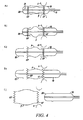
- FIGS 1a and 1b show an instrument 1 for implanting and radially deploying in situ an expandable, prosthetic cardiac valve.
- the prosthetic cardiac valve could be of the type described in U.S. Publication 2006/0178740 A1 .
- the instrument 1 could be used to deliver a variety of prosthetic cardiac valves and is not limited to any particular prosthetic valve structure.
- the instrument 1 includes a carrier portion 2 for enclosing and carrying the prosthetic device and a manipulation portion 3 that couples the carrier portion 2 to a control handle 4 where two actuator members (for instance two sliders 5, 6) are located.
- An optional third actuator is provided for that permits the carrier portion 2 to move forward, backward in relation to control handle 4.
- this feature permits for microadjustment of the carrier portion 2 and the valve prosthesis V in relation to a desired location while the control handle 4 is in a fixed location.
- a further optional actuator on the control handle 4 provides rotational adjustment of carrier portion 2 in relation to manipulation portion 3 and/or control handle 4. This permits the optional placement of the valve prosthesis through at least 360 degrees of rotation.
- the manipulation portion 3 may assume various configurations.
- Figure 1a shows a configuration where the portion 3 is comprised of a substantially rigid bar with alength (e.g., 10 cm) that will permit positioning of the carrier portion 2, and the prosthetic cardiac valve carried thereby, at an aortic valve site.
- instrument 1 is sized and dimensioned to permit easy surgical manipulation of the entire instruction as well as the actuators on the instrument without contacting parts of the subject in a way to interfere with the user's position of the valve prosthesis V.
- Figure 1b shows a second configuration, where the portion 3 is essentially comprised of an elongated, flexible catheter-like member that allows positioning of the carrier portion 2, and the prosthetic cardiac valve carried thereby, at an aortic valve site via transvascular catheterization (e.g., initiating at the femoral artery).
- This second configuration is also amenable for use in the sutureless or transapical implantation techniques.
- the flexible, catheter-like member is braided or otherwise adapted to facilitate transmission of torque from the handle 4 to the carrier portion 2, such that the operator may effect radial positioning of the carrier portion 2 during the implantation procedure.
- Other features as described for the embodiment in Figure 1a may also be added to the embodiment in Fig. 1b .
- the instrument 1 is adapted for use with a separate delivery tool.
- the instrument 1, for example, may be sized and shaped for delivery through a lumen of a tube or trocar during a "sutureless" or transapical delivery technique.
- the instrument 1 may be adapted for delivery through a working lumen of a delivery or guide catheter.
- the operator may first deliver a guide catheter through the patient's vasculature to the implant site and then advance the instrument 1 through the lumen.
- the instrument 1 includes an axial lumen extending from a proximal end to a distal end. The lumen is sized to allow introduction and advancement of the instrument 1 over a previously-im-planted guide wire.
- other techniques known in the art are used to reach the implantation site from a location outside the patient's body.
- the carrier portion 2 includes two deployment elements 10, 20, each independently operable to allow the expansion of at least one corresponding, radially expandable portion of the implant device.
- the cardiac valve prosthesis indicated as a whole as V, which is disclosed in U.S. Publication 2006/0178740 A1
- two such radially expandable portions are provided situated respectively at the inflow end IF and the outflow end OF for the pulsated blood flow through the prosthesis.
- the cardiac valve prosthesis may include more than two expandable members and, likewise, the carrier portion 2 may include more than two independent deployment elements.
- the valve prosthesis may be seff-ex-panding (e.g., made from a superelastic material such as Nitinol) or may require expansion by another device (e.g., balloon expansion).
- FIG. 2 illustrates an embodiment for use with a self-expanding cardiac valve prosthesis.
- the cardiacvalve prosthesis V is arranged within the carrier portion 2, such that an expandable portion IF and an expandable portion OF are each located within one of the deployment elements 10, 20.
- Each deployment element 10, 20 may be formed as a collar, cap or sheath.
- the elements 10,20 are porous (or have apertures) such that blood flow is facilitated prior, during and after placement of prosthesis V.
- Each deployment element 10, 20 is able to constrain the portions IF, OF in a radially contracted position, against the elastic strength of its constituent material.
- the portions IF, OF are able to radially expand, as a result of their characteristics of superelasticity, only when released from the deployment element 10, 20.
- the release of the portions IF, OF is obtained by causing an axial movement of the deploymentelements 10, 20 along the main axisX2 of the carrier portion 2.
- the operator e.g., physician
- causes this axial movement by manipulating the sliders 5 and 6, which are coupled to the deployment elements 10, 20.
- an optional micro-blood pump is operatively linked to the deployment elements 10 or 20 (or forms a part of the carrier portion 2), and serves to facilitate the movement of blood in a desired direction during the prosthesis placement procedure.
- the micro-blood pump can have a variable flow rate functionality to regulate blood flow as desired.
- expansion of the radially expandable portions IF, OF is caused by a positive expansion action exerted by the deployment elements 10, 20.
- the deployment elements 10, 20 are comprised of expandable balloons onto which the portions IF, OF are coupled (e.g., "crimped") in a radially contracted position.
- the operator causes radial expansion of the portions IF, OF by causing expansion of the balloons, using any of a variety of techniques.
- Figures 3-5 illustrate exemplary deployment techniques for the embodiment wherein the expandable portions IF, OF are made of a self-expandable material.
- the armature of the prosthetic cardiac valve prosthesis V is schematically shown (i.e., the valve leaflets are not shown).
- the armature includes the expandable entry (inflow) portion IF and the expandable exit (outflow) portion OF, which are connected axially by anchoring formations P.
- the formations P are spaced at 120° intervals about the armature circumference and are configured to radially protrude from the prosthesis V so as to penetrate into the sinuses of Valsalva.
- the inflow end IF of the prosthesis V is located in correspondence with the aortic annulus, thereby facing the left ventricle.
- the profile of the aortic annulus is shown schematically by the dashed lines A in Figures 3-5 .
- the outflow end OF is located in the ascending line of the aorta, in a position immediately distal to the sinuses of Valsalva, wherein the formations P extend.
- This dimensioning can take the form in one embodiment of appropriate tailored protuberances that permit the anchoring elements to rest in an appropriately contracted position prior to positioning.
- Figures 3-5 show a carrier portion 2 having two deployment elements 10, 20 each of which is capable of "encapsulating” (on one embodiment) or restraining a respective one of the inflow IF and outflow OF portions, to constrain the portions IF, OF from radially expanding.
- Both the elements 10, 20 can be arranged to slide longitudinally with respect to the principal axis X2 of the carrier portion 2.
- the elements 10, 20 slide down and rotate around the principal axis X2 (e.g. in a cork screw fashion).
- the axial (and optional rotational) movement of the elements 10,20 is obtained, according to exemplary embodiments, via the sliders 5, 6 provided on the handle 4 at the proximal end of the manipulation portion 3 of the instrument 1.
- the slider 5 may act on the deployment element 20 through a respective control wire or tendon 21, while the slider 6 may act on the deployment element 10 through a tubular control sheath 11 slidably arranged over the tendon 21, with both the sheath 11 and tendon 21 slidable along the axis X2.
- an internal surface of the elements 10, 20 comprise a low-friction or lubricious material, such as an ultra-high molecular weight material or PTFE (e.g., Teflon®).
- a low-friction or lubricious material such as an ultra-high molecular weight material or PTFE (e.g., Teflon®).
- PTFE ultra-high molecular weight material
- other surfaces of the elements 10,20 or any other parts of device 1 are coated or made from a low-friction material to provide for ease of insertion and manipulation within a subject.
- the sheath 11 is movable in a distal-to-proximal direction, so that the sheath and thus the element 10 move or slide "backwards" with respect to the carrier portion 2.
- the sliding movement of the tendon 21 will take place in a proximal-to-distal direction, so that the tendon and thus the element 20 move or slide "forward" with respect to the carrier portion 2.
- movement of the elements 10, 20 is obtained by manipulating rigid actuation members from the handle 4.
- the device 1 is shown as being manually operable by a user, it is within the spirit of the invention, to have device 1 and the various positioning elements actuated by sensors (positional) and movement of the various elements of the device control by servo-motors, a microprocessor, and the like (e.g., computer controlled). It is appreciated that placement of the prosthesis V may be more precisely controlled through computer control and mechanical movement of the various elements of device.
- Figures 3-5 are deliberately simplified for clarity of representation and do not take into account, for instance, the fact that the portion 3 of the instrument may include other control tendons/sheaths and/or ducts for inflating the post-expansion balloons (see Figure 6 ). Also, the element 20 could be actuated by means of a sheath rather than a tendon. Also, whatever their specific form of embodiment, the actuator members 11, 21 of the deployment elements 10, 20 may also have associated locking means (not shown, but of a known type) to prevent undesired actuation of the deployment elements 10, 20.
- the deployment elements 10, 20 are actuatable entirely independently of each other. This gives the operator complete freedom in selecting which of the portions IF, OF to deploy first according to the specific implantation method or conditions.
- Figures 3a-3e illustrate use of the instrument 1 for a "retrograde” approach (e.g., in the case of sutureless or percutaneous implantation), to the valve annulus, wherein the cardiac valve prosthesis V approaches the valve annulus from the aortic arch.
- FIG 3a (as in the following Figures 4a and 5a ), the cardiac valve prosthesis V is shown mounted in or carried by the carrier portion 2 of the instrument 1, such that the deployment elements 10, 20 constrain the annular ends IF, OF of the prosthesis V in a radially contracted position.
- Figure 3b shows the element 10 retracted axially with respect to the axis X2 of the carrier portion 2 a sufficient distance to uncover and release the formations P, which are then able to expand (e.g., due to their superelastic construction) such that they protrude beyond the diameter of the elements 10, 20.
- the formations P are allowed to expand, while the remaining portions of the prosthesis V are maintained in a radially contracted configuration.
- the operator can take the necessary action for ensuring the appropriate positioning of the prosthesis V in correspondence with the sinuses of Valsalva SV.
- the profile of the sinuses of Valsalva are shown schematically in Figure 3b by the dashed lines SV.
- Prosthesis V has elements sized and dimensioned to completely conform to the sinuses Valsalva in one variant of the invention.
- Such appropriate positioning includes both axial positioning (i.e. avoiding deploying the prosthetic valve V too far "upstream” or too far “downstream” of the desired position with the ensuing negative effect that the inflow end IF is not correctly positioned with respect to the valve annulus A) and radial positioning.
- the sinuses of Valsalva are configured as a hollow, three-lobed structure. Accordingly, accurately positioning each formation P of the prosthesis V in a respective sinus of Valsalva will ensure the correct positioning or angular orientation of the prosthetic valve as a whole, which will ensure that the leaflets of the prosthetic valve are correctly oriented (i.e., extend at the angular positions of the annulus where the natural valve leaflets were located before removal).
- the instrument 1 may further include various structures or features to assist the operator in obtaining the appropriate axial positioning with respect to the aortic annulus and radial positioning with respect to the sinuses of Valsalva.
- the instrument 1 (or the guide catheter or delivery tube), for example may include a lumen sufficient to allow the injection of contrast fluid to a location at the implantation site.
- this lumen would have an opening located past the inflow end IF or the prosthesis V, such that any injected contrast fluid would then flow back toward the prosthesis V, thereby enabling the operator to obtain a visual image of the implantation site, including an image of the sinuses of Valsalva.
- the prosthesis V may include radiopaque markers disposed at appropriate locations to assist in this positioning.
- the carrier portion 2 and the prosthesis V may be arranged from the beginning in the configuration represented in Figure 3b , namely with the formations P already protruding radially with respect to the profile of the prosthesis, while the annular end portions IF, OF are constrained in a radially contracted position by the elements 10, 20.
- the element 10 will have a sufficient length only to cover the axial extension of the annular end portion OF, as it need not radially constrain the formations P.
- Figure 3c shows the element 20 displaced distally with respect to the prosthesis V by the tendon 21.
- the element 20 was displaced a length sufficient to uncover the annular inflow portion IF, such that the portion IF is able to expand radially to assume the desired anchoring position at the valve annulus A.
- This release of the inflow portion IF takes place while the prosthetic valve V is still precisely retained and controlled by the instrument 1, such that it will not move or "jump" with respect to the valve annulus during the expansion of the portion IF.
- the prosthetic implantation process progresses by sliding the deployment element 10 so that it releases the outflow annular portion OF.
- the portion OF can then radially expand against the aortic wall, thus completing the second phase of the implantation operation of the prosthesis V.
- the carrier portion 2 and the instrument 1 as a whole can be withdrawn with respect to the implantation site through the center of the prosthesis V.
- the carrier portion 2 is withdrawn after the deployment elements 10,20 have been brought back to their initial positions, that is after having caused the elements 10, 20 to slide, in a proximal-to-distal and in a distal-to-proximal direction, respectively.
- the sequence of operations represented in Figures 3a-3e may be accomplished with a pulsating heart and without interrupting the natural circulation of blood.
- FIGS 4a-4e show an implantation procedure of a prosthesis V, according to another embodiment of the present invention. This procedure is similar to the procedure shown in Figures 3a-3e , but Figures 4a-4e show an "antegrade" approach, typical of a transapical implantation procedure.
- the prosthesis V mounted in the carrier portion 2 is advanced to the implantation site (e.g., aortic valve) through the left ventricle.
- the implantation site e.g., aortic valve
- the same criteria and principles will also apply to different valve types (e.g. mitral).
- Various techniques for accessing the aortic valve site through the left ventricle are known in the art.
- One exemplary technique for transapical delivery is disclosed in U.S. Publication 2005/0240200 .
- Figures 4a-4e are substantially identical to Figures 3a-3e , except that the position assumed by the prosthetic valve V is inverted. Accordingly, in the case of the intervention of "antegrade” type of Figures 4a-4e , the carrier portion 2 of the instrument 1 with the prosthesis V mounted therein is passed completely through the valve annulus A, so as to position the inflow portion IF in correspondence with the valve annulus A. As it is appreciated the device 1 is configured and sized and dimensioned so that it is capable of delivering the prosthesis V in both an antegrade and a retrograde intervention.
- the deployment element 20 After withdrawing the deployment element 10, so as to release the formations P ( Figure 4b ), the deployment element 20 is advanced distally, so as to release and allow the outflow annular end portion OF to radially expand against the aortic wall downstream of the sinuses of Valsalva (see Figure 4c ). At this point, the operator is still in a position to ensure that the prosthesis has the required correct angular position by making sure that the formations P each correctly engage a corresponding sinus. If the formations P do not properly align with the sinuses of Valsalva, the operator may use the instrument to apply a torque to the prosthesis V, thereby causing a rotation of the prosthesis V into the proper angular position.
- the tendon 21 includes a stop (not shown) configured to prohibit axial motion of the inflow portion IF.
- This stop may help prevent axial movement of the inflow portion IF during distal motion of the of the deployment element 20, thereby ensuring that the outflow portion OF is released before the inflow portion IF.
- the procedure progresses by bringing the deployment elements 10, 20 back towards their initial position with the ensuing retraction of the instrument 1 from the inflow portion IF of the valve ( Figure 4e ).
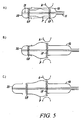
- Figures 5a-5c which correspond closely to the sequence of Figures 4a-4c , show that (also for a procedure of the "antegrade” type) it is possible to effect the two-step implantation sequence of Figures 4a-4e by deploying the end portions IF and OF of the prosthetic valve V in the reverse order.
- the inflow portion IF is expanded first by operating the deployment element 10 to release the corresponding inflow portion IF.
- the implantation procedure then proceeds, as schematically represented in Figure 5c , with the second step of this two-step procedure, namely with the deployment element 20 advanced distally with respect to the prosthesis V so as to release the expandable outflow portion OF.
- the outflow portion OF is thus free to expand against the aortic wall in a region downstream of the sinuses of Valsalva into which the formations P protrude.
- FIGS 5a-5c also apply in the case of a "retrograde" procedure, as shown in Figures 3a-3e .
- the deployment elements 10, 20 are adapted to be activated entirety independently of each other, the operator is free to choose the most suitable deployment sequence (inflow first and then outflow; outflow first and then inflow) as a function of the specific conditions of intervention. This sequence may be entirely independent of access to the implantation site being of the retrograde or antegrade type.
- FIGs 6 and 7 schematically illustrate embodiments in which the carrier portion 2 of the instrument 1 includes a balloon 7 at locations corresponding to at least one or to both annular ends of the cardiac valve prosthesis V.
- This balloon may be of any known type (e.g. of the type currently used in expanding stents or the like in a body lumen, which therefore does not require a detailed description to be provided herein) and is intended for use in realizing a "post-expansion" of the corresponding end portion IF, OF of the prosthesis V, so as to radially urge it against the wall of the implantation lumen.
- the balloon 7 can be selectively expanded (by inflating it with well known means and criteria) in such a way as to produce a radial expansion of the expandable portion associated therewith (here the end portion OF).
- This technique may be useful to avoid movementor "jumping" of the prosthesis V during implantation. For instance, if the operator fears that deployment of the inflow end portion IF in correspondence of the aortic annulus A may give rise to an undesired longitudinal displacement of the valve prosthesis V as a whole, while the inflow portion IF is being released by the element 10 arid expands to engage the aortic annulus A, a post-ex-pansion balloon 7 associated with the outflow end OF can be inflated. In this way, as long as the post-expansion balloon 7 is kept dilated, the outflow end OF is urged and thus safely anchored to the lumen wall and any undesired displacement of the prosthetic valve V in an axial direction is prevented. Once the inflow portion IF is safely positioned at the aortic annulus A, the balloon 7 can be deflated and the instrument 1 withdrawn.
- Figures 7, 8 and 9 schematically illustrate, without the intent of making any specific distinctions between “antegrade” and “retrograde” approaches and any specific choice as to which end portion, inflow IF or outflow OF, is to be deployed first, that the same two-step mechanism for independently deploying the two end portions IF, OF illustrated in Figures 3 , 4 and 5 can be implemented in the case of prostheses V including end portions IF, OF whose radial expansion is obtained via a positive outward expansion action exerted by means of deployment elements 10, 20 altogether constituted by expandable balloons.
- These may be.balloons of any known type and substantially correspond, from a structural point of view, to the post-expansion balloons (see for instance the balloon 7 of Figure 6 ).
- a cardiac valve prosthesis V includes one or more self-expandable portions (having associated deployment elements 10, 20 of the type illustrated in Figures 2-5 ) as well as one or more portions radially expandable via an expandable deployment element (such as a balloon as illustrated in Figures 7-9 ).
- the same balloon may be used both as an expansion balloon ( Figures 7, 8 and 9 ), and as a post-expansion balloon ( Figure 6 ).
- the elements 10, 20 are formed of a material that permits them to collapse after deployment of the prosthesis V. It is appreciated that this permits the entire device to be more easily removed from the subject
- Figures 10a-10d which substantially correspond to Figures 5a-5c , illustrate an embodiment associating with either or both of the annular end portions IF, OF of the prosthesis V and "anti-skid" locking member 22.
- This member is primarily intended to prevent any undesired sliding movement of the end portion (IF and/or OF) with respect to its deployment element lengthwise of the carrier portion 2.
- Such a locking member is preferably associated with (at least) the annular end portion to be deployed second in the two-step deployment process of the prosthetic valve V described herein.
- the locking member 22 takes the form of a hub positioned at the distal end of a tubular member 23 having the wire 21 slidably arranged therein.
- the sheath 11 surrounds the tubular member 23 and is adapted to slide thereon so that the locking member 22 is capable of maintaining at a fixed axial position (e.g. via end flanges 220) the annular outflow portion OF with which the locking member is associated.
- the annular end portion in question is thus prevented from sliding axially of the deployment element 20, at least as long as the annular end portion OF is radially constrained by the deployment element 20.
- the arrangement described makes it possible to adjust the position of the annular end portion locked by the locking member (and the position of the valve prosthesis V as a whole) both axially and angularly to the implantation site. This applies more or less until the annular portion expands to the point where further displacement is prevented by engagement of the annular portion with the valve annulus or the aortic wall. Additionally, the presence of the locking mem ber(s) 22 facilitates possible recovery of the prosthetic valve V in case the implantation procedure is to be aborted.
Landscapes
- Health & Medical Sciences (AREA)
- Cardiology (AREA)
- Engineering & Computer Science (AREA)
- Biomedical Technology (AREA)
- Oral & Maxillofacial Surgery (AREA)
- Transplantation (AREA)
- Heart & Thoracic Surgery (AREA)
- Vascular Medicine (AREA)
- Life Sciences & Earth Sciences (AREA)
- Animal Behavior & Ethology (AREA)
- General Health & Medical Sciences (AREA)
- Public Health (AREA)
- Veterinary Medicine (AREA)
- Mechanical Engineering (AREA)
- Prostheses (AREA)
Claims (10)
- Dispositif (1) pour déployer une prothèse de valve cardiaque (V) comprenant une pluralité de parties annulaires expansibles (IF, OF) au niveau d'un anneau de valve correspondant, ladite pluralité comprenant deux parties d'extrémité annulaires radialement expansibles (IF, OF), dans lequel la pluralité de parties d'extrémité annulaires radialement expansibles (IF, OF) comprend une partie d'entrée annulaire (IF), associée à l'entrée de sang, et une partie de sortie annulaire (OF) associée à la sortie de sang, lesdites parties d'extrémité annulaires radialement expansibles étant respectivement situées au niveau d'une extrémité d'entrée (IF) et d'une extrémité de sortie (OF) pour l'écoulement de sang pulsé à travers la prothèse, et sont raccordées axialement par des formations d'ancrage (P), le dispositif (1) comprenant deux éléments de déploiement indépendamment fonctionnels (10, 20) pouvant fonctionner pour déployer indépendamment deux parties d'extrémité annulaires radialement expansibles (IF, OF) de la prothèse de valve cardiaque (V), dans lequel chacun desdits éléments de déploiement (10, 20) est configuré pour retenir une partie respective des parties d'entrée (IF) et de sortie (OF), afin d'empêcher lesdites parties (IF, OF) de subir une expansion radiale et a une longueur suffisante uniquement pour couvrir l'extension axiale d'une partie d'extrémité annulaire (IF, OF) respective, de sorte que lesdites formations d'ancrage (P) ne sont pas radialement contraintes.
- Dispositif (1) selon la revendication 1, dans lequel la prothèse de valve cardiaque (V) est une prothèse de valve aortique.
- Dispositif (1) selon la revendication 1, dans lequel les parties d'extrémité annulaires radialement expansibles (IF, OF) sont fabriquées à partir d'un matériau super élastique, de sorte que les parties (IF, OF) sont auto-expansibles.
- Dispositif (1) selon la revendication 3, dans lequel la pluralité d'éléments de déploiement (10, 20) comprennent un premier élément de support (10 ; 20), pouvant fonctionner entre une première position pour retenir radialement la partie d'entrée annulaire (IF) et une seconde position pour libérer la partie d'entrée annulaire (IF), et un second élément de support (20; 10) pouvant fonctionner entre une première position pour retenir radialement la partie de sortie annulaire (OF) et une seconde position pour libérer la partie de sortie annulaire (OF).
- Dispositif (1) selon la revendication 1, comprenant en outre une poignée de commande (4) couplée de manière opérationnelle aux éléments de déploiement (10, 20), de sorte qu'un opérateur peut manipuler la poignée (4) pour actionner les éléments déploiement (10, 20).
- Dispositif (1) selon la revendication 3, dans lequel la pluralité d'éléments de déploiement (10, 20) comprend un premier collier (10; 20) configuré pour retenir radialement la partie d'entrée annulaire (IF) et un second collier (20; 10) configuré pour retenir radialement la partie de sortie annulaire (OF).
- Dispositif (1) selon la revendication 6, dans lequel l'instrument de déploiement comprend un élément de précontrainte (21) pouvant fonctionner (5) à partir de la poignée de commande (4) afin de provoquer le déplacement axial de l'un (20) parmi les premier et second colliers (10, 20).
- Dispositif (1) selon la revendication 7, dans lequel l'instrument de déploiement comprend une gaine pouvant être actionnée (6) à partir de la poignée de commande (4) pour provoquer le déplacement axial de l'un (10) parmi les premier et second colliers (10, 20).
- Dispositif (1) selon la revendication 7, dans lequel l'élément de précontrainte (21) comprend une butée pour empêcher le mouvement axial de l'une parmi la partie d'entrée annulaire (IF) et la partie de sortie annulaire (OF), alors que la partie reste disposée à l'intérieur du collier correspondant.
- Dispositif (1) selon la revendication , dans lequel l'un des premier et second colliers (10, 20) comprend une surface interne réalisée à partir d'un matériau à faible friction.
Priority Applications (1)
| Application Number | Priority Date | Filing Date | Title |
|---|---|---|---|
| EP10155332.9A EP2238947B2 (fr) | 2006-12-19 | 2006-12-19 | Instrument pour le déploiement in situ de prothèses valvulaires cardiaques |
Applications Claiming Priority (2)
| Application Number | Priority Date | Filing Date | Title |
|---|---|---|---|
| EP10155332.9A EP2238947B2 (fr) | 2006-12-19 | 2006-12-19 | Instrument pour le déploiement in situ de prothèses valvulaires cardiaques |
| EP20060126552 EP1935377B1 (fr) | 2006-12-19 | 2006-12-19 | Instrument pour le déploiement in situ de prothèses valvulaires cardiaques |
Related Parent Applications (2)
| Application Number | Title | Priority Date | Filing Date |
|---|---|---|---|
| EP06126552.6 Division | 2006-12-19 | ||
| EP20060126552 Division EP1935377B1 (fr) | 2006-12-19 | 2006-12-19 | Instrument pour le déploiement in situ de prothèses valvulaires cardiaques |
Publications (4)
| Publication Number | Publication Date |
|---|---|
| EP2238947A2 EP2238947A2 (fr) | 2010-10-13 |
| EP2238947A3 EP2238947A3 (fr) | 2011-07-06 |
| EP2238947B1 EP2238947B1 (fr) | 2013-01-23 |
| EP2238947B2 true EP2238947B2 (fr) | 2016-04-13 |
Family
ID=37909685
Family Applications (3)
| Application Number | Title | Priority Date | Filing Date |
|---|---|---|---|
| EP10155332.9A Active EP2238947B2 (fr) | 2006-12-19 | 2006-12-19 | Instrument pour le déploiement in situ de prothèses valvulaires cardiaques |
| EP20060126552 Active EP1935377B1 (fr) | 2006-12-19 | 2006-12-19 | Instrument pour le déploiement in situ de prothèses valvulaires cardiaques |
| EP08159301A Withdrawn EP1967164A3 (fr) | 2006-12-19 | 2006-12-19 | Instrument pour le déploiement in situ de prothèses valvulaires cardiaques |
Family Applications After (2)
| Application Number | Title | Priority Date | Filing Date |
|---|---|---|---|
| EP20060126552 Active EP1935377B1 (fr) | 2006-12-19 | 2006-12-19 | Instrument pour le déploiement in situ de prothèses valvulaires cardiaques |
| EP08159301A Withdrawn EP1967164A3 (fr) | 2006-12-19 | 2006-12-19 | Instrument pour le déploiement in situ de prothèses valvulaires cardiaques |
Country Status (2)
| Country | Link |
|---|---|
| EP (3) | EP2238947B2 (fr) |
| DE (1) | DE602006013167D1 (fr) |
Cited By (1)
| Publication number | Priority date | Publication date | Assignee | Title |
|---|---|---|---|---|
| US11684474B2 (en) | 2018-01-25 | 2023-06-27 | Edwards Lifesciences Corporation | Delivery system for aided replacement valve recapture and repositioning post-deployment |
Families Citing this family (62)
| Publication number | Priority date | Publication date | Assignee | Title |
|---|---|---|---|---|
| EP2481375A3 (fr) | 2004-10-02 | 2013-12-04 | Endoheart AG | Dispositifs de délivrer et d'extraction des valvules cardiaques |
| US8092520B2 (en) | 2005-11-10 | 2012-01-10 | CardiAQ Technologies, Inc. | Vascular prosthesis connecting stent |
| WO2008013915A2 (fr) | 2006-07-28 | 2008-01-31 | Arshad Quadri | Prothèse à valve percutanée et système et procédé pour implanter une telle prothèse |
| EP1935378B1 (fr) | 2006-12-19 | 2014-09-17 | Sorin Group Italia S.r.l. | Dispositif pour la mise en place d'une valve cardiaque |
| US8070799B2 (en) | 2006-12-19 | 2011-12-06 | Sorin Biomedica Cardio S.R.L. | Instrument and method for in situ deployment of cardiac valve prostheses |
| US20090105794A1 (en) * | 2007-09-07 | 2009-04-23 | Ziarno W Andrew | Microprocessor controlled delivery system for cardiac valve prosthesis |
| US8114154B2 (en) | 2007-09-07 | 2012-02-14 | Sorin Biomedica Cardio S.R.L. | Fluid-filled delivery system for in situ deployment of cardiac valve prostheses |
| US8808367B2 (en) | 2007-09-07 | 2014-08-19 | Sorin Group Italia S.R.L. | Prosthetic valve delivery system including retrograde/antegrade approach |
| DE102008012113A1 (de) | 2008-03-02 | 2009-09-03 | Transcatheter Technologies Gmbh | Stent, welcher vom expandierten Zustand erneut im Durchmesser kontrolliert verringerbar ist |
| US8403983B2 (en) | 2008-09-29 | 2013-03-26 | Cardiaq Valve Technologies, Inc. | Heart valve |
| US8986361B2 (en) * | 2008-10-17 | 2015-03-24 | Medtronic Corevalve, Inc. | Delivery system for deployment of medical devices |
| US8834563B2 (en) | 2008-12-23 | 2014-09-16 | Sorin Group Italia S.R.L. | Expandable prosthetic valve having anchoring appendages |
| CA2756049C (fr) | 2009-04-15 | 2017-05-02 | Impala, Inc. | Implant vasculaire et systeme d'introduction |
| EP2250975B1 (fr) | 2009-05-13 | 2013-02-27 | Sorin Biomedica Cardio S.r.l. | Dispositif pour la livraison in situ de valvules cardiaques |
| EP2250970B1 (fr) | 2009-05-13 | 2012-12-26 | Sorin Biomedica Cardio S.r.l. | Dispositif pour interventions chirurgicales |
| US8353953B2 (en) | 2009-05-13 | 2013-01-15 | Sorin Biomedica Cardio, S.R.L. | Device for the in situ delivery of heart valves |
| US8579964B2 (en) | 2010-05-05 | 2013-11-12 | Neovasc Inc. | Transcatheter mitral valve prosthesis |
| WO2011163275A2 (fr) | 2010-06-21 | 2011-12-29 | Cardiaq Valve Technologies, Inc. | Prothèse de valvule cardiaque |
| EP2618784B1 (fr) | 2010-09-23 | 2016-05-25 | Edwards Lifesciences CardiAQ LLC | Valvules prothétiques et dispositifs de pose |
| US9308087B2 (en) | 2011-04-28 | 2016-04-12 | Neovasc Tiara Inc. | Sequentially deployed transcatheter mitral valve prosthesis |
| US9554897B2 (en) | 2011-04-28 | 2017-01-31 | Neovasc Tiara Inc. | Methods and apparatus for engaging a valve prosthesis with tissue |
| US20120303048A1 (en) | 2011-05-24 | 2012-11-29 | Sorin Biomedica Cardio S.R.I. | Transapical valve replacement |
| CN103997990A (zh) | 2011-06-21 | 2014-08-20 | 托尔福公司 | 人工心脏瓣膜装置及相关系统和方法 |
| US11202704B2 (en) | 2011-10-19 | 2021-12-21 | Twelve, Inc. | Prosthetic heart valve devices, prosthetic mitral valves and associated systems and methods |
| EP3943047B1 (fr) | 2011-10-19 | 2023-08-30 | Twelve, Inc. | Dispositif de remplacement de valvule cardiaque |
| US9039757B2 (en) | 2011-10-19 | 2015-05-26 | Twelve, Inc. | Prosthetic heart valve devices, prosthetic mitral valves and associated systems and methods |
| EP3984500A1 (fr) | 2011-10-19 | 2022-04-20 | Twelve, Inc. | Dispositifs de valvules cardiaques prothétiques |
| US9345573B2 (en) | 2012-05-30 | 2016-05-24 | Neovasc Tiara Inc. | Methods and apparatus for loading a prosthesis onto a delivery system |
| EP2695586B1 (fr) | 2012-08-10 | 2019-05-08 | Sorin Group Italia S.r.l. | Prothèse de valvule et kit |
| US20140277427A1 (en) | 2013-03-14 | 2014-09-18 | Cardiaq Valve Technologies, Inc. | Prosthesis for atraumatically grasping intralumenal tissue and methods of delivery |
| US9730791B2 (en) | 2013-03-14 | 2017-08-15 | Edwards Lifesciences Cardiaq Llc | Prosthesis for atraumatically grasping intralumenal tissue and methods of delivery |
| US9572665B2 (en) | 2013-04-04 | 2017-02-21 | Neovasc Tiara Inc. | Methods and apparatus for delivering a prosthetic valve to a beating heart |
| CN106170269B (zh) | 2014-02-21 | 2019-01-11 | 爱德华兹生命科学卡迪尔克有限责任公司 | 用于瓣膜替代品的受控部署的递送装置 |
| US10390943B2 (en) | 2014-03-17 | 2019-08-27 | Evalve, Inc. | Double orifice device for transcatheter mitral valve replacement |
| WO2015179423A1 (fr) | 2014-05-19 | 2015-11-26 | Cardiaq Valve Technologies, Inc. | Valvule mitrale de remplacement ayant un rabat annulaire |
| ES2631808T3 (es) | 2014-09-24 | 2017-09-05 | Sorin Group Italia S.R.L. | Un soporte para prótesis de válvula cardiaca, disposición de almacenamiento correspondiente, instrumento de instalación, y kit |
| US10376363B2 (en) | 2015-04-30 | 2019-08-13 | Edwards Lifesciences Cardiaq Llc | Replacement mitral valve, delivery system for replacement mitral valve and methods of use |
| WO2016209970A1 (fr) | 2015-06-22 | 2016-12-29 | Edwards Lifescience Cardiaq Llc | Implant de valve cardiaque pouvant être commandé de manière active et procédés de commande de celui-ci |
| US10092400B2 (en) | 2015-06-23 | 2018-10-09 | Edwards Lifesciences Cardiaq Llc | Systems and methods for anchoring and sealing a prosthetic heart valve |
| US10117744B2 (en) | 2015-08-26 | 2018-11-06 | Edwards Lifesciences Cardiaq Llc | Replacement heart valves and methods of delivery |
| US10575951B2 (en) | 2015-08-26 | 2020-03-03 | Edwards Lifesciences Cardiaq Llc | Delivery device and methods of use for transapical delivery of replacement mitral valve |
| US10350066B2 (en) | 2015-08-28 | 2019-07-16 | Edwards Lifesciences Cardiaq Llc | Steerable delivery system for replacement mitral valve and methods of use |
| CN113633435A (zh) | 2016-01-29 | 2021-11-12 | 内奥瓦斯克迪亚拉公司 | 用于防止流出阻塞的假体瓣膜 |
| US10363138B2 (en) | 2016-11-09 | 2019-07-30 | Evalve, Inc. | Devices for adjusting the curvature of cardiac valve structures |
| US10426616B2 (en) | 2016-11-17 | 2019-10-01 | Evalve, Inc. | Cardiac implant delivery system |
| CN113893064A (zh) | 2016-11-21 | 2022-01-07 | 内奥瓦斯克迪亚拉公司 | 用于快速收回经导管心脏瓣膜递送系统的方法和系统 |
| US10702378B2 (en) | 2017-04-18 | 2020-07-07 | Twelve, Inc. | Prosthetic heart valve device and associated systems and methods |
| US10709591B2 (en) | 2017-06-06 | 2020-07-14 | Twelve, Inc. | Crimping device and method for loading stents and prosthetic heart valves |
| US10729541B2 (en) | 2017-07-06 | 2020-08-04 | Twelve, Inc. | Prosthetic heart valve devices and associated systems and methods |
| US10786352B2 (en) | 2017-07-06 | 2020-09-29 | Twelve, Inc. | Prosthetic heart valve devices and associated systems and methods |
| WO2019010303A1 (fr) | 2017-07-06 | 2019-01-10 | Edwards Lifesciences Corporation | Système et éléments de pose manoeuvrables |
| CA3073834A1 (fr) | 2017-08-25 | 2019-02-28 | Neovasc Tiara Inc. | Prothese de valvule mitrale transcatheter a deploiement sequentiel |
| US11051934B2 (en) | 2018-02-28 | 2021-07-06 | Edwards Lifesciences Corporation | Prosthetic mitral valve with improved anchors and seal |
| EP3796874A1 (fr) | 2018-05-23 | 2021-03-31 | Sorin Group Italia S.r.l. | Système de chargement pour prothèse implantable et procédé de chargement associé |
| EP3796872B1 (fr) * | 2018-05-23 | 2022-07-20 | Corcym S.r.l. | Dispositif pour l'administration in-situ de prothèses de valvules cardiaques |
| AU2019374743B2 (en) | 2018-11-08 | 2022-03-03 | Neovasc Tiara Inc. | Ventricular deployment of a transcatheter mitral valve prosthesis |
| CA3132629A1 (fr) | 2019-03-11 | 2020-09-17 | Corcym S.R.L. | Procede de fourniture de caracteristiques sur un materiau implantable mettant en jeu l'utilisation du laser, protheses cardiovasculaires implantables et materiaux implantables tra ites selon ledit procede |
| US11602429B2 (en) | 2019-04-01 | 2023-03-14 | Neovasc Tiara Inc. | Controllably deployable prosthetic valve |
| WO2020210652A1 (fr) | 2019-04-10 | 2020-10-15 | Neovasc Tiara Inc. | Valvule prothétique à circulation sanguine naturelle |
| US11452599B2 (en) | 2019-05-02 | 2022-09-27 | Twelve, Inc. | Fluid diversion devices for hydraulic delivery systems and associated methods |
| CA3140925A1 (fr) | 2019-05-20 | 2020-11-26 | Neovasc Tiara Inc. | Dispositif d'introduction avec mecanisme d'hemostase |
| AU2020295566B2 (en) | 2019-06-20 | 2023-07-20 | Neovasc Tiara Inc. | Low profile prosthetic mitral valve |
Citations (3)
| Publication number | Priority date | Publication date | Assignee | Title |
|---|---|---|---|---|
| WO2004019825A1 (fr) † | 2002-08-13 | 2004-03-11 | Fraunhofer-Gesellschaft zur Förderung der angewandten Forschung e.V. | Dispositif d'implantation et de fixation de protheses de valvules cardiaques |
| WO2007021708A1 (fr) † | 2005-08-17 | 2007-02-22 | Medtronic Vascular, Inc. | Appareil et procede de liberation d'endoprothese-greffon a l'aide d'une cupule |
| EP1986579B1 (fr) † | 2006-02-21 | 2012-09-26 | Cook Medical Technologies LLC | Systeme de deploiement de gaine fractionnee |
Family Cites Families (6)
| Publication number | Priority date | Publication date | Assignee | Title |
|---|---|---|---|---|
| US5957949A (en) * | 1997-05-01 | 1999-09-28 | World Medical Manufacturing Corp. | Percutaneous placement valve stent |
| US6280467B1 (en) * | 1998-02-26 | 2001-08-28 | World Medical Manufacturing Corporation | Delivery system for deployment and endovascular assembly of a multi-stage stented graft |
| US10219899B2 (en) | 2004-04-23 | 2019-03-05 | Medtronic 3F Therapeutics, Inc. | Cardiac valve replacement systems |
| JP2007530244A (ja) | 2004-03-31 | 2007-11-01 | メッド・インスティテュート・インコーポレイテッド | 人工弁を有する腔内グラフト |
| US7462191B2 (en) * | 2004-06-30 | 2008-12-09 | Edwards Lifesciences Pvt, Inc. | Device and method for assisting in the implantation of a prosthetic valve |
| ITTO20050074A1 (it) | 2005-02-10 | 2006-08-11 | Sorin Biomedica Cardio Srl | Protesi valvola cardiaca |
-
2006
- 2006-12-19 EP EP10155332.9A patent/EP2238947B2/fr active Active
- 2006-12-19 EP EP20060126552 patent/EP1935377B1/fr active Active
- 2006-12-19 EP EP08159301A patent/EP1967164A3/fr not_active Withdrawn
- 2006-12-19 DE DE200660013167 patent/DE602006013167D1/de active Active
Patent Citations (3)
| Publication number | Priority date | Publication date | Assignee | Title |
|---|---|---|---|---|
| WO2004019825A1 (fr) † | 2002-08-13 | 2004-03-11 | Fraunhofer-Gesellschaft zur Förderung der angewandten Forschung e.V. | Dispositif d'implantation et de fixation de protheses de valvules cardiaques |
| WO2007021708A1 (fr) † | 2005-08-17 | 2007-02-22 | Medtronic Vascular, Inc. | Appareil et procede de liberation d'endoprothese-greffon a l'aide d'une cupule |
| EP1986579B1 (fr) † | 2006-02-21 | 2012-09-26 | Cook Medical Technologies LLC | Systeme de deploiement de gaine fractionnee |
Cited By (1)
| Publication number | Priority date | Publication date | Assignee | Title |
|---|---|---|---|---|
| US11684474B2 (en) | 2018-01-25 | 2023-06-27 | Edwards Lifesciences Corporation | Delivery system for aided replacement valve recapture and repositioning post-deployment |
Also Published As
| Publication number | Publication date |
|---|---|
| EP2238947A3 (fr) | 2011-07-06 |
| EP1967164A3 (fr) | 2009-01-28 |
| EP1935377A1 (fr) | 2008-06-25 |
| DE602006013167D1 (de) | 2010-05-06 |
| EP1935377B1 (fr) | 2010-03-24 |
| EP2238947A2 (fr) | 2010-10-13 |
| EP2238947B1 (fr) | 2013-01-23 |
| EP1967164A2 (fr) | 2008-09-10 |
Similar Documents
| Publication | Publication Date | Title |
|---|---|---|
| EP2238947B2 (fr) | Instrument pour le déploiement in situ de prothèses valvulaires cardiaques | |
| US8070799B2 (en) | Instrument and method for in situ deployment of cardiac valve prostheses | |
| EP2033597B1 (fr) | Système de mise en place remplie de fluide pour le déploiement in situ de prothèses valvulaires cardiaques | |
| US8114154B2 (en) | Fluid-filled delivery system for in situ deployment of cardiac valve prostheses | |
| US11103346B2 (en) | Expandable member for deploying a prosthetic device | |
| EP2033593B1 (fr) | Système de livraison contrôlée à microprocesseur pour prothèse valvulaire cardiaque | |
| AU2017378495B2 (en) | Deployment systems, tools, and methods for delivering an anchoring device for a prosthetic valve | |
| EP3360513B1 (fr) | Valvule cardiaque prothétique | |
| US9452046B2 (en) | Methods and apparatuses for deploying minimally-invasive heart valves | |
| WO2014078135A1 (fr) | Ensemble et procédé de déploiement de prothèse valvulaire | |
| US20230270551A1 (en) | Catheters for implants and medical procedures and methods of use thereof | |
| US20240024110A1 (en) | Delivery systems for implants |
Legal Events
| Date | Code | Title | Description |
|---|---|---|---|
| PUAI | Public reference made under article 153(3) epc to a published international application that has entered the european phase |
Free format text: ORIGINAL CODE: 0009012 |
|
| AC | Divisional application: reference to earlier application |
Ref document number: 1935377 Country of ref document: EP Kind code of ref document: P |
|
| AK | Designated contracting states |
Kind code of ref document: A2 Designated state(s): DE FR GB IT |
|
| PUAL | Search report despatched |
Free format text: ORIGINAL CODE: 0009013 |
|
| AK | Designated contracting states |
Kind code of ref document: A3 Designated state(s): DE FR GB IT |
|
| 17P | Request for examination filed |
Effective date: 20111230 |
|
| GRAP | Despatch of communication of intention to grant a patent |
Free format text: ORIGINAL CODE: EPIDOSNIGR1 |
|
| GRAP | Despatch of communication of intention to grant a patent |
Free format text: ORIGINAL CODE: EPIDOSNIGR1 |
|
| GRAS | Grant fee paid |
Free format text: ORIGINAL CODE: EPIDOSNIGR3 |
|
| GRAA | (expected) grant |
Free format text: ORIGINAL CODE: 0009210 |
|
| AC | Divisional application: reference to earlier application |
Ref document number: 1935377 Country of ref document: EP Kind code of ref document: P |
|
| AK | Designated contracting states |
Kind code of ref document: B1 Designated state(s): DE FR GB IT |
|
| REG | Reference to a national code |
Ref country code: GB Ref legal event code: FG4D |
|
| RAP2 | Party data changed (patent owner data changed or rights of a patent transferred) |
Owner name: SORIN GROUP ITALIA S.R.L. |
|
| REG | Reference to a national code |
Ref country code: DE Ref legal event code: R096 Ref document number: 602006034428 Country of ref document: DE Effective date: 20130328 |
|
| REG | Reference to a national code |
Ref country code: GB Ref legal event code: 732E Free format text: REGISTERED BETWEEN 20130530 AND 20130605 |
|
| PLBI | Opposition filed |
Free format text: ORIGINAL CODE: 0009260 |
|
| PLAX | Notice of opposition and request to file observation + time limit sent |
Free format text: ORIGINAL CODE: EPIDOSNOBS2 |
|
| 26 | Opposition filed |
Opponent name: STOLMAR, MATTHIAS Effective date: 20131021 |
|
| REG | Reference to a national code |
Ref country code: DE Ref legal event code: R026 Ref document number: 602006034428 Country of ref document: DE Effective date: 20131021 |
|
| PLAF | Information modified related to communication of a notice of opposition and request to file observations + time limit |
Free format text: ORIGINAL CODE: EPIDOSCOBS2 |
|
| PLBB | Reply of patent proprietor to notice(s) of opposition received |
Free format text: ORIGINAL CODE: EPIDOSNOBS3 |
|
| PLAB | Opposition data, opponent's data or that of the opponent's representative modified |
Free format text: ORIGINAL CODE: 0009299OPPO |
|
| PLAB | Opposition data, opponent's data or that of the opponent's representative modified |
Free format text: ORIGINAL CODE: 0009299OPPO |
|
| R26 | Opposition filed (corrected) |
Opponent name: STOLMAR, MATTHIAS Effective date: 20131021 |
|
| R26 | Opposition filed (corrected) |
Opponent name: STOLMAR, MATTHIAS Effective date: 20131021 |
|
| REG | Reference to a national code |
Ref country code: FR Ref legal event code: PLFP Year of fee payment: 10 |
|
| PUAH | Patent maintained in amended form |
Free format text: ORIGINAL CODE: 0009272 |
|
| STAA | Information on the status of an ep patent application or granted ep patent |
Free format text: STATUS: PATENT MAINTAINED AS AMENDED |
|
| 27A | Patent maintained in amended form |
Effective date: 20160413 |
|
| AK | Designated contracting states |
Kind code of ref document: B2 Designated state(s): DE FR GB IT |
|
| REG | Reference to a national code |
Ref country code: DE Ref legal event code: R102 Ref document number: 602006034428 Country of ref document: DE |
|
| REG | Reference to a national code |
Ref country code: FR Ref legal event code: PLFP Year of fee payment: 11 |
|
| REG | Reference to a national code |
Ref country code: FR Ref legal event code: PLFP Year of fee payment: 12 |
|
| REG | Reference to a national code |
Ref country code: DE Ref legal event code: R081 Ref document number: 602006034428 Country of ref document: DE Owner name: CORCYM S.R.L., IT Free format text: FORMER OWNER: SORIN BIOMEDICA CARDIO S.R.L., SALUGGIA, VERCELLI, IT |
|
| REG | Reference to a national code |
Ref country code: GB Ref legal event code: 732E Free format text: REGISTERED BETWEEN 20220210 AND 20220216 |
|
| REG | Reference to a national code |
Ref country code: GB Ref legal event code: 732E Free format text: REGISTERED BETWEEN 20221110 AND 20221116 |
|
| PGFP | Annual fee paid to national office [announced via postgrant information from national office to epo] |
Ref country code: IT Payment date: 20221219 Year of fee payment: 17 |
|
| P01 | Opt-out of the competence of the unified patent court (upc) registered |
Effective date: 20230530 |
|
| PGFP | Annual fee paid to national office [announced via postgrant information from national office to epo] |
Ref country code: GB Payment date: 20231215 Year of fee payment: 18 |
|
| PGFP | Annual fee paid to national office [announced via postgrant information from national office to epo] |
Ref country code: FR Payment date: 20231229 Year of fee payment: 18 |
|
| PGFP | Annual fee paid to national office [announced via postgrant information from national office to epo] |
Ref country code: DE Payment date: 20231221 Year of fee payment: 18 |