EP2238831A1 - Schnelles, leichtgewichtiges, geformtes Scherbrett mit verbesserter hydrodynamischer Effizienz und Verfahren zur Verwendung und Herstellung - Google Patents
Schnelles, leichtgewichtiges, geformtes Scherbrett mit verbesserter hydrodynamischer Effizienz und Verfahren zur Verwendung und Herstellung Download PDFInfo
- Publication number
- EP2238831A1 EP2238831A1 EP10169271A EP10169271A EP2238831A1 EP 2238831 A1 EP2238831 A1 EP 2238831A1 EP 10169271 A EP10169271 A EP 10169271A EP 10169271 A EP10169271 A EP 10169271A EP 2238831 A1 EP2238831 A1 EP 2238831A1
- Authority
- EP
- European Patent Office
- Prior art keywords
- trawl door
- trawl
- door
- profile
- deflector body
- Prior art date
- Legal status (The legal status is an assumption and is not a legal conclusion. Google has not performed a legal analysis and makes no representation as to the accuracy of the status listed.)
- Withdrawn
Links
- 238000004519 manufacturing process Methods 0.000 title abstract description 37
- 238000000034 method Methods 0.000 title description 26
- 230000001965 increasing effect Effects 0.000 title description 9
- XLYOFNOQVPJJNP-UHFFFAOYSA-N water Substances O XLYOFNOQVPJJNP-UHFFFAOYSA-N 0.000 abstract description 55
- 229920002994 synthetic fiber Polymers 0.000 description 105
- 239000000463 material Substances 0.000 description 60
- 229920001971 elastomer Polymers 0.000 description 57
- 239000000806 elastomer Substances 0.000 description 57
- 239000007787 solid Substances 0.000 description 56
- 229920002647 polyamide Polymers 0.000 description 40
- 239000004952 Polyamide Substances 0.000 description 38
- 229920001778 nylon Polymers 0.000 description 33
- 239000004677 Nylon Substances 0.000 description 32
- 239000007788 liquid Substances 0.000 description 32
- 239000013536 elastomeric material Substances 0.000 description 22
- -1 aliphatic dicarboxylic acids Chemical class 0.000 description 21
- 238000010276 construction Methods 0.000 description 21
- 238000013461 design Methods 0.000 description 21
- 238000003892 spreading Methods 0.000 description 19
- 230000007480 spreading Effects 0.000 description 19
- 229910000831 Steel Inorganic materials 0.000 description 18
- 239000010959 steel Substances 0.000 description 18
- VGGSQFUCUMXWEO-UHFFFAOYSA-N Ethene Chemical compound C=C VGGSQFUCUMXWEO-UHFFFAOYSA-N 0.000 description 16
- 239000005977 Ethylene Substances 0.000 description 16
- 229920001577 copolymer Polymers 0.000 description 15
- 239000000203 mixture Substances 0.000 description 15
- 229920000642 polymer Polymers 0.000 description 14
- 229920002292 Nylon 6 Polymers 0.000 description 12
- JBKVHLHDHHXQEQ-UHFFFAOYSA-N epsilon-caprolactam Chemical compound O=C1CCCCCN1 JBKVHLHDHHXQEQ-UHFFFAOYSA-N 0.000 description 12
- 230000008569 process Effects 0.000 description 11
- 230000002708 enhancing effect Effects 0.000 description 10
- 238000006116 polymerization reaction Methods 0.000 description 9
- 239000000126 substance Substances 0.000 description 9
- 238000010539 anionic addition polymerization reaction Methods 0.000 description 8
- 238000010107 reaction injection moulding Methods 0.000 description 8
- 239000011800 void material Substances 0.000 description 8
- 150000003951 lactams Chemical class 0.000 description 7
- 230000004048 modification Effects 0.000 description 7
- 238000012986 modification Methods 0.000 description 7
- 238000012545 processing Methods 0.000 description 7
- 239000004711 α-olefin Substances 0.000 description 7
- 229920001400 block copolymer Polymers 0.000 description 6
- 239000003054 catalyst Substances 0.000 description 6
- 150000004985 diamines Chemical class 0.000 description 6
- 239000006260 foam Substances 0.000 description 6
- 239000004619 high density foam Substances 0.000 description 6
- POILWHVDKZOXJZ-ARJAWSKDSA-M (z)-4-oxopent-2-en-2-olate Chemical compound C\C([O-])=C\C(C)=O POILWHVDKZOXJZ-ARJAWSKDSA-M 0.000 description 5
- UGFAIRIUMAVXCW-UHFFFAOYSA-N Carbon monoxide Chemical compound [O+]#[C-] UGFAIRIUMAVXCW-UHFFFAOYSA-N 0.000 description 5
- 229910002091 carbon monoxide Inorganic materials 0.000 description 5
- QHZOMAXECYYXGP-UHFFFAOYSA-N ethene;prop-2-enoic acid Chemical compound C=C.OC(=O)C=C QHZOMAXECYYXGP-UHFFFAOYSA-N 0.000 description 5
- 229920000573 polyethylene Polymers 0.000 description 5
- JHWNWJKBPDFINM-UHFFFAOYSA-N Laurolactam Chemical compound O=C1CCCCCCCCCCCN1 JHWNWJKBPDFINM-UHFFFAOYSA-N 0.000 description 4
- 229920000305 Nylon 6,10 Polymers 0.000 description 4
- 229920002302 Nylon 6,6 Polymers 0.000 description 4
- 125000004432 carbon atom Chemical group C* 0.000 description 4
- 238000006243 chemical reaction Methods 0.000 description 4
- 238000000576 coating method Methods 0.000 description 4
- 239000011162 core material Substances 0.000 description 4
- 230000001747 exhibiting effect Effects 0.000 description 4
- 239000012530 fluid Substances 0.000 description 4
- 229920001519 homopolymer Polymers 0.000 description 4
- 230000007774 longterm Effects 0.000 description 4
- 238000007747 plating Methods 0.000 description 4
- 229920000768 polyamine Polymers 0.000 description 4
- 229920001155 polypropylene Polymers 0.000 description 4
- 239000002994 raw material Substances 0.000 description 4
- CERQOIWHTDAKMF-UHFFFAOYSA-N Methacrylic acid Chemical compound CC(=C)C(O)=O CERQOIWHTDAKMF-UHFFFAOYSA-N 0.000 description 3
- 229920000299 Nylon 12 Polymers 0.000 description 3
- 229920003189 Nylon 4,6 Polymers 0.000 description 3
- 239000004743 Polypropylene Substances 0.000 description 3
- VSCWAEJMTAWNJL-UHFFFAOYSA-K aluminium trichloride Chemical compound Cl[Al](Cl)Cl VSCWAEJMTAWNJL-UHFFFAOYSA-K 0.000 description 3
- 239000011248 coating agent Substances 0.000 description 3
- 239000003999 initiator Substances 0.000 description 3
- 238000003754 machining Methods 0.000 description 3
- 230000008018 melting Effects 0.000 description 3
- 238000002844 melting Methods 0.000 description 3
- 229910001092 metal group alloy Inorganic materials 0.000 description 3
- 229920000098 polyolefin Polymers 0.000 description 3
- 238000007711 solidification Methods 0.000 description 3
- 230000008023 solidification Effects 0.000 description 3
- 239000003381 stabilizer Substances 0.000 description 3
- 229920001897 terpolymer Polymers 0.000 description 3
- DVPHDWQFZRBFND-DMHDVGBCSA-N 1-o-[2-[(3ar,5r,6s,6ar)-2,2-dimethyl-6-prop-2-enoyloxy-3a,5,6,6a-tetrahydrofuro[2,3-d][1,3]dioxol-5-yl]-2-[4-[(2s,3r)-1-butan-2-ylsulfanyl-2-(2-chlorophenyl)-4-oxoazetidin-3-yl]oxy-4-oxobutanoyl]oxyethyl] 4-o-[(2s,3r)-1-butan-2-ylsulfanyl-2-(2-chloropheny Chemical group C1([C@H]2[C@H](C(N2SC(C)CC)=O)OC(=O)CCC(=O)OC(COC(=O)CCC(=O)O[C@@H]2[C@@H](N(C2=O)SC(C)CC)C=2C(=CC=CC=2)Cl)[C@@H]2[C@@H]([C@H]3OC(C)(C)O[C@H]3O2)OC(=O)C=C)=CC=CC=C1Cl DVPHDWQFZRBFND-DMHDVGBCSA-N 0.000 description 2
- 241001233242 Lontra Species 0.000 description 2
- FYYHWMGAXLPEAU-UHFFFAOYSA-N Magnesium Chemical compound [Mg] FYYHWMGAXLPEAU-UHFFFAOYSA-N 0.000 description 2
- TWRXJAOTZQYOKJ-UHFFFAOYSA-L Magnesium chloride Chemical compound [Mg+2].[Cl-].[Cl-] TWRXJAOTZQYOKJ-UHFFFAOYSA-L 0.000 description 2
- BAPJBEWLBFYGME-UHFFFAOYSA-N Methyl acrylate Chemical compound COC(=O)C=C BAPJBEWLBFYGME-UHFFFAOYSA-N 0.000 description 2
- 241001165050 Ocala Species 0.000 description 2
- 229920000034 Plastomer Polymers 0.000 description 2
- 239000005062 Polybutadiene Substances 0.000 description 2
- 239000004698 Polyethylene Substances 0.000 description 2
- PPBRXRYQALVLMV-UHFFFAOYSA-N Styrene Chemical compound C=CC1=CC=CC=C1 PPBRXRYQALVLMV-UHFFFAOYSA-N 0.000 description 2
- ATJFFYVFTNAWJD-UHFFFAOYSA-N Tin Chemical compound [Sn] ATJFFYVFTNAWJD-UHFFFAOYSA-N 0.000 description 2
- 239000004708 Very-low-density polyethylene Substances 0.000 description 2
- XTXRWKRVRITETP-UHFFFAOYSA-N Vinyl acetate Chemical compound CC(=O)OC=C XTXRWKRVRITETP-UHFFFAOYSA-N 0.000 description 2
- 239000000654 additive Substances 0.000 description 2
- 230000004075 alteration Effects 0.000 description 2
- 230000003466 anti-cipated effect Effects 0.000 description 2
- 230000015572 biosynthetic process Effects 0.000 description 2
- 229910052793 cadmium Inorganic materials 0.000 description 2
- BDOSMKKIYDKNTQ-UHFFFAOYSA-N cadmium atom Chemical compound [Cd] BDOSMKKIYDKNTQ-UHFFFAOYSA-N 0.000 description 2
- YKYOUMDCQGMQQO-UHFFFAOYSA-L cadmium dichloride Chemical compound Cl[Cd]Cl YKYOUMDCQGMQQO-UHFFFAOYSA-L 0.000 description 2
- 238000005266 casting Methods 0.000 description 2
- 238000004891 communication Methods 0.000 description 2
- 238000005336 cracking Methods 0.000 description 2
- 150000001991 dicarboxylic acids Chemical class 0.000 description 2
- ILRSCQWREDREME-UHFFFAOYSA-N dodecanamide Chemical compound CCCCCCCCCCCC(N)=O ILRSCQWREDREME-UHFFFAOYSA-N 0.000 description 2
- 238000005516 engineering process Methods 0.000 description 2
- CGPRUXZTHGTMKW-UHFFFAOYSA-N ethene;ethyl prop-2-enoate Chemical compound C=C.CCOC(=O)C=C CGPRUXZTHGTMKW-UHFFFAOYSA-N 0.000 description 2
- 239000003365 glass fiber Substances 0.000 description 2
- 229920001903 high density polyethylene Polymers 0.000 description 2
- 239000004700 high-density polyethylene Substances 0.000 description 2
- 229920000554 ionomer Polymers 0.000 description 2
- RBTARNINKXHZNM-UHFFFAOYSA-K iron trichloride Chemical compound Cl[Fe](Cl)Cl RBTARNINKXHZNM-UHFFFAOYSA-K 0.000 description 2
- 230000033001 locomotion Effects 0.000 description 2
- 229920001684 low density polyethylene Polymers 0.000 description 2
- 239000004702 low-density polyethylene Substances 0.000 description 2
- 229910052749 magnesium Inorganic materials 0.000 description 2
- 239000011777 magnesium Substances 0.000 description 2
- HQKMJHAJHXVSDF-UHFFFAOYSA-L magnesium stearate Chemical compound [Mg+2].CCCCCCCCCCCCCCCCCC([O-])=O.CCCCCCCCCCCCCCCCCC([O-])=O HQKMJHAJHXVSDF-UHFFFAOYSA-L 0.000 description 2
- 230000014759 maintenance of location Effects 0.000 description 2
- 229920001179 medium density polyethylene Polymers 0.000 description 2
- 239000004701 medium-density polyethylene Substances 0.000 description 2
- 229910052751 metal Inorganic materials 0.000 description 2
- 239000002184 metal Substances 0.000 description 2
- 229920003023 plastic Polymers 0.000 description 2
- 239000004033 plastic Substances 0.000 description 2
- 229920002857 polybutadiene Polymers 0.000 description 2
- 229920001748 polybutylene Polymers 0.000 description 2
- 229920000570 polyether Polymers 0.000 description 2
- 229920006124 polyolefin elastomer Polymers 0.000 description 2
- 239000002243 precursor Substances 0.000 description 2
- 229920001384 propylene homopolymer Polymers 0.000 description 2
- 239000013535 sea water Substances 0.000 description 2
- 239000000243 solution Substances 0.000 description 2
- 229920001169 thermoplastic Polymers 0.000 description 2
- 239000004416 thermosoftening plastic Substances 0.000 description 2
- 229920001862 ultra low molecular weight polyethylene Polymers 0.000 description 2
- 229920001866 very low density polyethylene Polymers 0.000 description 2
- JIAARYAFYJHUJI-UHFFFAOYSA-L zinc dichloride Chemical compound [Cl-].[Cl-].[Zn+2] JIAARYAFYJHUJI-UHFFFAOYSA-L 0.000 description 2
- LFKXWKGYHQXRQA-FDGPNNRMSA-N (z)-4-hydroxypent-3-en-2-one;iron Chemical compound [Fe].C\C(O)=C\C(C)=O.C\C(O)=C\C(C)=O LFKXWKGYHQXRQA-FDGPNNRMSA-N 0.000 description 1
- SHWZFQPXYGHRKT-FDGPNNRMSA-N (z)-4-hydroxypent-3-en-2-one;nickel Chemical compound [Ni].C\C(O)=C\C(C)=O.C\C(O)=C\C(C)=O SHWZFQPXYGHRKT-FDGPNNRMSA-N 0.000 description 1
- ZQVHTTABFLHMPA-UHFFFAOYSA-N 2-(4-chlorophenoxy)-5-nitropyridine Chemical compound N1=CC([N+](=O)[O-])=CC=C1OC1=CC=C(Cl)C=C1 ZQVHTTABFLHMPA-UHFFFAOYSA-N 0.000 description 1
- MFWFDRBPQDXFRC-UHFFFAOYSA-N 4-hydroxypent-3-en-2-one;vanadium Chemical compound [V].CC(O)=CC(C)=O.CC(O)=CC(C)=O.CC(O)=CC(C)=O MFWFDRBPQDXFRC-UHFFFAOYSA-N 0.000 description 1
- NIXOWILDQLNWCW-UHFFFAOYSA-M Acrylate Chemical compound [O-]C(=O)C=C NIXOWILDQLNWCW-UHFFFAOYSA-M 0.000 description 1
- 241000251468 Actinopterygii Species 0.000 description 1
- GVNWZKBFMFUVNX-UHFFFAOYSA-N Adipamide Chemical compound NC(=O)CCCCC(N)=O GVNWZKBFMFUVNX-UHFFFAOYSA-N 0.000 description 1
- ZOXJGFHDIHLPTG-UHFFFAOYSA-N Boron Chemical compound [B] ZOXJGFHDIHLPTG-UHFFFAOYSA-N 0.000 description 1
- BNZLTPCWOLWBNJ-UHFFFAOYSA-M Br[Mg] Chemical compound Br[Mg] BNZLTPCWOLWBNJ-UHFFFAOYSA-M 0.000 description 1
- INVGSXKPOIHXPB-UHFFFAOYSA-N C=C.[C-]#[O+] Chemical compound C=C.[C-]#[O+] INVGSXKPOIHXPB-UHFFFAOYSA-N 0.000 description 1
- OYPRJOBELJOOCE-UHFFFAOYSA-N Calcium Chemical compound [Ca] OYPRJOBELJOOCE-UHFFFAOYSA-N 0.000 description 1
- VEXZGXHMUGYJMC-UHFFFAOYSA-M Chloride anion Chemical compound [Cl-] VEXZGXHMUGYJMC-UHFFFAOYSA-M 0.000 description 1
- 239000004709 Chlorinated polyethylene Substances 0.000 description 1
- 229910021556 Chromium(III) chloride Inorganic materials 0.000 description 1
- 229910021580 Cobalt(II) chloride Inorganic materials 0.000 description 1
- IMROMDMJAWUWLK-UHFFFAOYSA-N Ethenol Chemical compound OC=C IMROMDMJAWUWLK-UHFFFAOYSA-N 0.000 description 1
- CWYNVVGOOAEACU-UHFFFAOYSA-N Fe2+ Chemical compound [Fe+2] CWYNVVGOOAEACU-UHFFFAOYSA-N 0.000 description 1
- 229910021578 Iron(III) chloride Inorganic materials 0.000 description 1
- 239000002841 Lewis acid Substances 0.000 description 1
- 229920010126 Linear Low Density Polyethylene (LLDPE) Polymers 0.000 description 1
- 239000004594 Masterbatch (MB) Substances 0.000 description 1
- 229910021586 Nickel(II) chloride Inorganic materials 0.000 description 1
- 229920000459 Nitrile rubber Polymers 0.000 description 1
- 239000004687 Nylon copolymer Substances 0.000 description 1
- 239000004721 Polyphenylene oxide Substances 0.000 description 1
- 239000004809 Teflon Substances 0.000 description 1
- 229920006362 Teflon® Polymers 0.000 description 1
- 229910021551 Vanadium(III) chloride Inorganic materials 0.000 description 1
- HCHKCACWOHOZIP-UHFFFAOYSA-N Zinc Chemical compound [Zn] HCHKCACWOHOZIP-UHFFFAOYSA-N 0.000 description 1
- MGSCVPSSIVOYMY-UHFFFAOYSA-N [V+3].CC[O-].CC[O-].CC[O-] Chemical compound [V+3].CC[O-].CC[O-].CC[O-] MGSCVPSSIVOYMY-UHFFFAOYSA-N 0.000 description 1
- 239000012190 activator Substances 0.000 description 1
- 125000002252 acyl group Chemical group 0.000 description 1
- 230000000996 additive effect Effects 0.000 description 1
- 125000002947 alkylene group Chemical group 0.000 description 1
- 239000004411 aluminium Substances 0.000 description 1
- 229910052782 aluminium Inorganic materials 0.000 description 1
- XAGFODPZIPBFFR-UHFFFAOYSA-N aluminium Chemical compound [Al] XAGFODPZIPBFFR-UHFFFAOYSA-N 0.000 description 1
- 125000003277 amino group Chemical group 0.000 description 1
- 125000000129 anionic group Chemical group 0.000 description 1
- 125000003118 aryl group Chemical group 0.000 description 1
- 229910052788 barium Inorganic materials 0.000 description 1
- DSAJWYNOEDNPEQ-UHFFFAOYSA-N barium atom Chemical compound [Ba] DSAJWYNOEDNPEQ-UHFFFAOYSA-N 0.000 description 1
- WDIHJSXYQDMJHN-UHFFFAOYSA-L barium chloride Chemical compound [Cl-].[Cl-].[Ba+2] WDIHJSXYQDMJHN-UHFFFAOYSA-L 0.000 description 1
- 229910001626 barium chloride Inorganic materials 0.000 description 1
- DJHZYHWLGNJISM-FDGPNNRMSA-L barium(2+);(z)-4-oxopent-2-en-2-olate Chemical compound [Ba+2].C\C([O-])=C\C(C)=O.C\C([O-])=C\C(C)=O DJHZYHWLGNJISM-FDGPNNRMSA-L 0.000 description 1
- 230000005540 biological transmission Effects 0.000 description 1
- 229910052796 boron Inorganic materials 0.000 description 1
- NTXGQCSETZTARF-UHFFFAOYSA-N buta-1,3-diene;prop-2-enenitrile Chemical compound C=CC=C.C=CC#N NTXGQCSETZTARF-UHFFFAOYSA-N 0.000 description 1
- 229910052791 calcium Inorganic materials 0.000 description 1
- 239000011575 calcium Substances 0.000 description 1
- QAZYYQMPRQKMAC-FDGPNNRMSA-L calcium;(z)-4-oxopent-2-en-2-olate Chemical compound [Ca+2].C\C([O-])=C\C(C)=O.C\C([O-])=C\C(C)=O QAZYYQMPRQKMAC-FDGPNNRMSA-L 0.000 description 1
- JHLCADGWXYCDQA-UHFFFAOYSA-N calcium;ethanolate Chemical compound [Ca+2].CC[O-].CC[O-] JHLCADGWXYCDQA-UHFFFAOYSA-N 0.000 description 1
- 150000001735 carboxylic acids Chemical class 0.000 description 1
- SOGXWMAAMKKQCB-UHFFFAOYSA-M chloroalumane Chemical compound Cl[AlH2] SOGXWMAAMKKQCB-UHFFFAOYSA-M 0.000 description 1
- QSWDMMVNRMROPK-UHFFFAOYSA-K chromium(3+) trichloride Chemical compound [Cl-].[Cl-].[Cl-].[Cr+3] QSWDMMVNRMROPK-UHFFFAOYSA-K 0.000 description 1
- WYYQVWLEPYFFLP-UHFFFAOYSA-K chromium(3+);triacetate Chemical compound [Cr+3].CC([O-])=O.CC([O-])=O.CC([O-])=O WYYQVWLEPYFFLP-UHFFFAOYSA-K 0.000 description 1
- 239000011636 chromium(III) chloride Substances 0.000 description 1
- 235000007831 chromium(III) chloride Nutrition 0.000 description 1
- MJSNUBOCVAKFIJ-LNTINUHCSA-N chromium;(z)-4-oxoniumylidenepent-2-en-2-olate Chemical compound [Cr].C\C(O)=C\C(C)=O.C\C(O)=C\C(C)=O.C\C(O)=C\C(C)=O MJSNUBOCVAKFIJ-LNTINUHCSA-N 0.000 description 1
- GVPFVAHMJGGAJG-UHFFFAOYSA-L cobalt dichloride Chemical compound [Cl-].[Cl-].[Co+2] GVPFVAHMJGGAJG-UHFFFAOYSA-L 0.000 description 1
- FCEOGYWNOSBEPV-FDGPNNRMSA-N cobalt;(z)-4-hydroxypent-3-en-2-one Chemical compound [Co].C\C(O)=C\C(C)=O.C\C(O)=C\C(C)=O FCEOGYWNOSBEPV-FDGPNNRMSA-N 0.000 description 1
- 150000001875 compounds Chemical class 0.000 description 1
- ZKXWKVVCCTZOLD-FDGPNNRMSA-N copper;(z)-4-hydroxypent-3-en-2-one Chemical compound [Cu].C\C(O)=C\C(C)=O.C\C(O)=C\C(C)=O ZKXWKVVCCTZOLD-FDGPNNRMSA-N 0.000 description 1
- 239000002178 crystalline material Substances 0.000 description 1
- 238000006073 displacement reaction Methods 0.000 description 1
- 230000000694 effects Effects 0.000 description 1
- 238000005265 energy consumption Methods 0.000 description 1
- XCKWFNSALCEAPW-UHFFFAOYSA-N ethanolate;tin(2+) Chemical compound [Sn+2].CC[O-].CC[O-] XCKWFNSALCEAPW-UHFFFAOYSA-N 0.000 description 1
- NNRZFZBJEDXBPK-UHFFFAOYSA-N ethanolate;titanium(3+) Chemical compound [Ti+3].CC[O-].CC[O-].CC[O-] NNRZFZBJEDXBPK-UHFFFAOYSA-N 0.000 description 1
- HQQADJVZYDDRJT-UHFFFAOYSA-N ethene;prop-1-ene Chemical group C=C.CC=C HQQADJVZYDDRJT-UHFFFAOYSA-N 0.000 description 1
- BXOUVIIITJXIKB-UHFFFAOYSA-N ethene;styrene Chemical compound C=C.C=CC1=CC=CC=C1 BXOUVIIITJXIKB-UHFFFAOYSA-N 0.000 description 1
- 229920006228 ethylene acrylate copolymer Polymers 0.000 description 1
- 229940117927 ethylene oxide Drugs 0.000 description 1
- 239000004744 fabric Substances 0.000 description 1
- 239000011152 fibreglass Substances 0.000 description 1
- 235000013332 fish product Nutrition 0.000 description 1
- 239000003063 flame retardant Substances 0.000 description 1
- 239000000446 fuel Substances 0.000 description 1
- 229930195733 hydrocarbon Natural products 0.000 description 1
- 150000002430 hydrocarbons Chemical class 0.000 description 1
- 230000001788 irregular Effects 0.000 description 1
- 239000004922 lacquer Substances 0.000 description 1
- 238000012693 lactam polymerization Methods 0.000 description 1
- 229940116335 lauramide Drugs 0.000 description 1
- 239000011968 lewis acid catalyst Substances 0.000 description 1
- 150000007517 lewis acids Chemical class 0.000 description 1
- 229920000092 linear low density polyethylene Polymers 0.000 description 1
- 239000004707 linear low-density polyethylene Substances 0.000 description 1
- 229910001629 magnesium chloride Inorganic materials 0.000 description 1
- 159000000003 magnesium salts Chemical class 0.000 description 1
- 235000019359 magnesium stearate Nutrition 0.000 description 1
- AKTIAGQCYPCKFX-FDGPNNRMSA-L magnesium;(z)-4-oxopent-2-en-2-olate Chemical compound [Mg+2].C\C([O-])=C\C(C)=O.C\C([O-])=C\C(C)=O AKTIAGQCYPCKFX-FDGPNNRMSA-L 0.000 description 1
- 229920001912 maleic anhydride grafted polyethylene Polymers 0.000 description 1
- 239000000155 melt Substances 0.000 description 1
- 150000002739 metals Chemical class 0.000 description 1
- 239000010445 mica Substances 0.000 description 1
- 229910052618 mica group Inorganic materials 0.000 description 1
- 239000012764 mineral filler Substances 0.000 description 1
- 239000000178 monomer Substances 0.000 description 1
- 238000000465 moulding Methods 0.000 description 1
- QMMRZOWCJAIUJA-UHFFFAOYSA-L nickel dichloride Chemical compound Cl[Ni]Cl QMMRZOWCJAIUJA-UHFFFAOYSA-L 0.000 description 1
- FJXWKBZRTWEWBJ-UHFFFAOYSA-N nonanediamide Chemical compound NC(=O)CCCCCCCC(N)=O FJXWKBZRTWEWBJ-UHFFFAOYSA-N 0.000 description 1
- 229920000620 organic polymer Polymers 0.000 description 1
- 239000003973 paint Substances 0.000 description 1
- 239000004014 plasticizer Substances 0.000 description 1
- 229920000728 polyester Polymers 0.000 description 1
- 229920005606 polypropylene copolymer Polymers 0.000 description 1
- 229920005629 polypropylene homopolymer Polymers 0.000 description 1
- 229920001296 polysiloxane Polymers 0.000 description 1
- 238000002360 preparation method Methods 0.000 description 1
- DQAKJEWZWDQURW-UHFFFAOYSA-N pyrrolidonecarboxylic acid Chemical compound OC(=O)N1CCCC1=O DQAKJEWZWDQURW-UHFFFAOYSA-N 0.000 description 1
- 229920005604 random copolymer Polymers 0.000 description 1
- 230000001105 regulatory effect Effects 0.000 description 1
- 230000002787 reinforcement Effects 0.000 description 1
- 239000012779 reinforcing material Substances 0.000 description 1
- 230000004044 response Effects 0.000 description 1
- 238000001175 rotational moulding Methods 0.000 description 1
- 238000006748 scratching Methods 0.000 description 1
- 230000002393 scratching effect Effects 0.000 description 1
- 238000000926 separation method Methods 0.000 description 1
- 230000035939 shock Effects 0.000 description 1
- 239000010935 stainless steel Substances 0.000 description 1
- 229910001220 stainless steel Inorganic materials 0.000 description 1
- AGGKEGLBGGJEBZ-UHFFFAOYSA-N tetramethylenedisulfotetramine Chemical compound C1N(S2(=O)=O)CN3S(=O)(=O)N1CN2C3 AGGKEGLBGGJEBZ-UHFFFAOYSA-N 0.000 description 1
- CMWCOKOTCLFJOP-UHFFFAOYSA-N titanium(3+) Chemical compound [Ti+3] CMWCOKOTCLFJOP-UHFFFAOYSA-N 0.000 description 1
- YONPGGFAJWQGJC-UHFFFAOYSA-K titanium(iii) chloride Chemical compound Cl[Ti](Cl)Cl YONPGGFAJWQGJC-UHFFFAOYSA-K 0.000 description 1
- 238000012795 verification Methods 0.000 description 1
- 238000003466 welding Methods 0.000 description 1
- 229910052725 zinc Inorganic materials 0.000 description 1
- 239000011701 zinc Substances 0.000 description 1
- 239000011592 zinc chloride Substances 0.000 description 1
- 235000005074 zinc chloride Nutrition 0.000 description 1
- NHXVNEDMKGDNPR-UHFFFAOYSA-N zinc;pentane-2,4-dione Chemical compound [Zn+2].CC(=O)[CH-]C(C)=O.CC(=O)[CH-]C(C)=O NHXVNEDMKGDNPR-UHFFFAOYSA-N 0.000 description 1
Images


Classifications
-
- A—HUMAN NECESSITIES
- A01—AGRICULTURE; FORESTRY; ANIMAL HUSBANDRY; HUNTING; TRAPPING; FISHING
- A01K—ANIMAL HUSBANDRY; AVICULTURE; APICULTURE; PISCICULTURE; FISHING; REARING OR BREEDING ANIMALS, NOT OTHERWISE PROVIDED FOR; NEW BREEDS OF ANIMALS
- A01K73/00—Drawn nets
- A01K73/02—Trawling nets
- A01K73/04—Devices for spreading or positioning, e.g. control thereof
- A01K73/045—Devices for spreading or positioning, e.g. control thereof for lateral sheering, e.g. trawl boards
Definitions
- the Present Invention relates generally to trawl doors, and more particularly to trawl doors having enhanced and rather high efficiency, lightness of weight In water and ease of manufacture.
- Trawl doors of the present invention are capable of the highest modern trawling speeds while also permitting the maximum scope length of main warp without sinking the trawl system below a desired elevation in the water column, thereby conserving optimal trawl opening and economy and controllability of trawl fishing operations.
- Modern trawl fisheries are complicated by an increase in operating costs due primarily to increasingly expensive fuel costs affecting both the catch of as well as the transportation to market of fish and value added fish product.
- the increase in operating costs in combination with the tendency of regulatory authorities to impose fixed catch quotas in one form or another have combined to force trawl fishing vessel operators to increase the efficiency of their trawl systems.
- One impact of this demand for increased efficiency of the trawl system is a demand for increased trawl door efficiency, and in particular an ever increasing need for trawl doors that are efficient at shallow depths and high speeds, as modern pelagic trawling increasingly requires economic operations at shallow depths and high speeds.
- any particular trawl door only exhibits optimum hydrodynamic efficiency at a certain angle of attack, just as any particular airfoil only exhibits optimum aerodynamic efficiency at a certain angle of attack of its chord to the airflow, and thus varying the angle of attack of a certain trawl door in order to regulate spread and water resistance forces necessarily means the trawl doors and thus the trawling vessel must operate at a reduced level of efficiency.
- some pelagic trawlers use two varying sizes and even different designs of trawl doors, despite the increased costs and inconvenience associated with such practice.
- one trawl door pair is larger in size than the other trawl door pair, and thus heavier in water, and is used at deeper trawling elevations with longer lengths of towing warps, where the trawl doors are able to properly spread both towing warps and trawl.
- it may be used with a wide body trawl at deeper depths.
- the second door pair may be smaller in size, and thus lighter weight in water as well as having less resistance in water, and is thus able to be operated with a high opening trawl at moderate depths and at higher speeds and higher elevations in the water column, although in such case it is not able to provide optimal spread for the towing vessel due to the smaller size of the trawl door.
- Trawl door design has evolved from otter boards and "V" shaped plates both of which have no camber at all, to modern trawl doors having camber.
- trawl door design occurs under the premise and experimentally thus far conventionally confirmed practice of designing the trawl door to deflect or thrust "inward” the greatest volume of water possible for the least drag.
- the premise of trawl door design in the field has been to generate the most "outwardly” directed force possible by virtue of the least energetic displacement of a given volume of water in an "inward" direction.
- U.S. Patent 4,180,935 shows a trawl door formed from a single main deflector body having a relatively thick profile width and a range of profile shapes similar to those found in many airfoils. It is taught that in the most preferred embodiment, the profile of the main deflector has an outer side that is convex and an inner side that is both convex (in the forward approximately third of the length of the profile) as well as concave (in the rear approximately two thirds of the length of the profile).
- This patent also teaches in particular that a profile for a main deflector and/or trawl door preferably does not have a purely concave inner surface (the natural curvature leading to the trailing edge not being counted as part of the inner surface).
- German patent DE 562 243 describes in 1931 a cambered profile made up of a number of aerofoil sections.
- U.S. Patent 4,640,037 shows a trawl door having inner concave and outer convex surfaces forming a cambered profile having a relatively thin width, and additionally incorporating lift enhancing slots in the leading edge of the main deflector body.
- the main deflector body itself is formed with a cambered profile that while being extremely thin, e.g. the thickness of a single one centimeter (1 cm) plate of steel, nonetheless has greater camber for its forward portion than for its rearward portion.
- trawl door having a thin thickness (i.e. the thickness of a single plate of sheet steel, such as one centimeter), symmetric camber both for the inner concave and outer convex surface, and at least one spoiler disposed forward of the deflector body's leading edge as all shown in U.S. 4,640,037 is widely used in trawl doors today.
- the profile of the main deflector body of this trawl door has a relatively wide profile, using widths similar to although seemingly lesser than those taught in U.S. 4,180,935 and includes a cambered profile wherein the camber defined by the curvature of the surface of outer side of the trawl door's main deflector body is convex and essentially oppositely symmetrical to the camber defined by the curvature of the surface of the inner side of the trawl door's main deflector body, which inner side is concave.
- the main deflector body of the NETS trawl door is considered as able to most economically displace "inward" (i.e. toward the center of the trawl, as well as toward the opposing trawl door) a given volume of water per unit time for a given water flow velocity as compared to other main deflector body designs, thereby creating an opposing force that, in keeping with Newton's second law forces the trawl door "outward" (i.e. away from the center of the trawl as well as away from the opposing trawl door).
- this considered highly efficient light weight in water NETS trawl door design does not incorporate lift enhancing structures disposed forward of the leading edge of the main deflector body, and in fact only includes for its lift generating shape a main deflector body.
- wing or "wing like” or “wing shape” is extensively used, and either or both refers to trawl doors wherein the leading edge of a trawl door has a "swept back" configuration, and/or where the main deflector body of such a trawl door is cambered, usually where the cambers created by the surfaces of the main deflector bodies outer and inner sides are symmetrical, and also where the camber created by surface of the main deflector body's outer side is substantial greater than the camber created by the surface of the main deflector body's inner side.
- wing shaped in reference to trawl doors means a trawl door construction wherein the leading edge of said "wing shaped” trawl doors takes the shape of a wide, horizontally oriented "V", much like a “delta wing” or a “swept wing”, while the profile of the trawl door's main deflector body (which may form the entire thrust creating structure of the trawl door) has symmetrical camber both defining the curvature of its inner side surface as well as defining the curvature of its outer side surface, from leading edge to trailing edge.
- Such trawl doors known as "wing shaped" trawl doors represent the state of the art in the field. They are held by the industry to be the best shape and construction possible for a trawl door and are dominant in use in the conventional pelagic trawl fishing industry.
- a highly efficient low-speed high-lift airfoil profile may be viewed by utilizing a software program known as "VisualFoil Version 4.1" produced and sold by Hanley Innovations/Dr. P. Hanley, Ocala, FL)".
- a maximally efficient low-speed high-lift airfoil profile is found in the "VisualFoil Version 4.1" software where it is known by the profile name and/or code "NACA-338117". None of the known art has suggested using this profile in any portion of known trawl doors.
- the most efficient conventional pelagic trawl door constructions are trawl door constructions whose profiles are rather thick in width relative to the length of the chord line, such as those thick width profiled trawl doors in the known art mentioned above.
- the relatively great thickness allows the trawl door to have a rather large volume for a given mass, thereby displacing more water for a given mass, and thus having a relatively low weight in water.
- a difficulty presented by the known art is that the most efficient of trawl doors known in the art are rather expensive to manufacture, and thus have not gained as wide use as less expensive alternatives.
- One of the reasons for the excessive manufacture cost of the most efficient conventional light weight in water trawl doors is that in order to make the trawl doors maximally efficient, it is necessary to make the trawl doors a certain minimum thickness, or width, in relation to their chord length, as mentioned above.
- light weight in water trawl doors may easily be twenty to thirty centimeters or more in thickness, as opposed to approximately one centimeter in thickness for heavier weight in water trawl doors.
- trawl doors have been constructed of a steel or other metallic shell formed with an internal core of high density foam. Such trawl doors are produced by NET Systems, Inc. (Bainbridge Island, Washington USA).
- the high density foam fills out most of the void space created by the metallic shell over a steel tension bearing frame.
- the high density foam is unusually expensive and the manufacture processes used to make such trawl doors are unusually expensive.
- the steel shell itself is formed from numerous steel plates bent and fixedly welded into position upon a steel framework, the interior void space of such a construction occupied by the foam.
- the manufacture process employed utilizes a large amount of costly high density foam, more steel than alternatively thinner trawl doors, and a great deal of manpower and machine time. Thus the high cost of such trawl doors.
- WO 01/84922 suggests the use of a trawl door having a core and outer covering comprising a cast material which can be a plastic material such as e.g. polyamide and the core material can be closed cell foam.
- the main difficulty in constructing trawl doors having the most efficient known shape for the main deflector is that due to the rather thick width of the main deflector, much steel must be used to create a shell.
- the shell either must form a cavity which is in open communication to the water environment to permit sea water to enter and exit the shell so as to neutralize pressures (i.e. it is not a closed space as the shell cannot tolerate high pressure at fishing depths, or else it would be far too heavy and expensive to create), which construction employs much steel and makes the trawl doors too heavy to be widely useful. Otherwise, if buoyancy is desired, much expensive high density foam must be used to occupy the inner void spaces within the steel shell, which construction and contemporaneous manufacture requirements makes the manufacture of the trawl doors too expensive to be widely affordable.
- EXTERIOR STRUCTURES OF TRAWL DOORS means those portions of a trawl door either that are (i) in communication with the outside or ambient environment; or (ii) only separated from the outside or ambient environment by a coating itself insufficiently durable to withstand without the additional support of further structure repeated impacts resultant of normal fishing operations, examples of such a coating including paints, lacquers, veneers, coatings, artificial skins or the like.
- FRONT OF CENTER means more proximal to the leading edge of the profile of a particular portion of a trawl door than the trailing edge of that same particular trawl door portion's same profile.
- RECEIVE(S) IMPACTS FRACTURE FREE means the ability of receiving collisions and other blows occurring during normal trawl fishing operations, including at the range of temperatures found in and about the surfaces of the world's seas and oceans, without incurring or developing fractures, despite possibly experiencing denting, marking, scuffing, scratching, chipping or other sculpting or ejection of material due to receiving such collisions and other blows.
- OPERATIONS means those collisions and other blows experienced by a trawl door during trawl fishing operations that are not so severe as to cause the fracture and/or cracking of a conventional high quality trawl door constructed of a high quality steel and/or other metal alloy, but may be sufficiently severe so as to cause the fracture and/or cracking of prior trawl doors employing synthetics in their exterior structures. '
- PROFILE means the cross sectional shape of a trawl door or of a portion of a trawl door as viewed in a plane perpendicular to the vertical dimension of the trawl door.
- TRAWL DOOR means any of a variety of essentially rigid structures having generally rigid deflectors (e.g. not formed of a foldable fabric as a kite) and capable of being deployed in a body of water behind a towing vessel, and usually attached at a fore end to a terminal end of a main towing warp or other towing line depending from the towing vessel and at an aft end to another line itself ultimately attached to another towed item.
- trawl doors have the function of converting a portion of forward motion and/or energy that is imparted by the towing vessel into horizontally directed force for the purpose of spreading in a generally horizontal orientation a trawl net, seismic surveillance towed array complex, paravane line or the like.
- the present invention is based upon the discovery that impact receiving and especially exterior portions of trawl doors may usefully be formed from synthetic materi6is capable of forming structures that withstand impacts resultant of normal trawl fishing operations without exhibiting fractures.
- Normal trawl fishing operations are those trawl fishing operations that would not fracture a standard, well constructed high quality steel and/or other metal alloy trawl door.
- Trawl doors of the present invention employ synthetics that receive impacts fracture free in order to form the exterior structures and tensile load bearing structures of modern trawl doors, including impact bearing structures of modern trawl doors, with no compromise in trawl door performance and longevity.
- the present invention in based upon the surprising discovery that a substantially more efficient trawl door may be created wherein the trawl door includes at least one and preferably two lift enhancing structures disposed forward of the leading edge of a single main deflector body, and the main deflector has a profile wherein:
- the synthetic material comprises preferably a polyamide (nylon) combined with an elastomer in such a ratio as to provide a material that withstand impacts fracture-free.
- Polyamides or Nylons
- Polycondensates of for example aliphatic dicarboxylic acids containing 4-12 carbon atoms with aliphatic diamines containing 4-12 carbon atoms and/or lactams containing 4-12 carbon atoms.
- polyamides examples include polyhexamethylene adipamide (nylon 6,6), polyhexamethylene azelamide (nylon 6,9), polyhexamethylene sebacamide (nylon 6,10), polyhexamethylene lauramide (nylon 6,12), polytetramethytene adipamide (nylon 4,6), polycaprolactam (nylon 6) and polylaurinolactam (nylon 12).
- the diamines and/or dicarboxylic acids can also be aromatic.
- Polyamides can also be built up of two or more dicarboxylic acids and/or two or more diamines, or of two or more lactams, while they can also consist of mixtures of two or more polyamides.
- the polyamide is Nylon-6 shown in Formula (I), obtainable by polymerization of caprolactam.
- the polyamide and elastomer form a copolymer, e.g. a block copolymer with alternating blocks of polyamide segments wherein Y is an alkylene group and m is an integer greater than one, and residues of elastomeric polymers, such as e.g. polyethers, hydrocarbons, polyesters, polysiloxanes or combinations thereof.
- elastomeric polymers such as e.g. polyethers, hydrocarbons, polyesters, polysiloxanes or combinations thereof.
- Nylon copolymers and processes for their productions are disclosed in e.g. U.S. patent No. 4,617,355 ; U.S. patent No. 4,590,243 , and patent application WO 94/17124 .
- Suitable elastomers include polyolefin elastomer or plastomer especially a polyolefin elastomer or plastomer made using a single-site catalyst system (for example a homogeneously branched ethylene polymer such as a substantially linear ethylene interpolymer or a homogeneously branched linear ethylene interpolymer).
- a single-site catalyst system for example a homogeneously branched ethylene polymer such as a substantially linear ethylene interpolymer or a homogeneously branched linear ethylene interpolymer.
- suitable polyolefins include, for example, polyethylene (ethylene homopolymer), ethylene/alpha-olefin interpolymers, alpha-olefin homopolymers, such as polypropylene(propylene homopolymer), alpha-olefin interpolymers, such as interpolymers of polypropylene and an alpha-olefin having at least 4 carbon atoms.
- polyolefins include, for example, but are not limited to substantially linear ethylene polymers, homogeneously branched linear ethylene polymers, heterogeneously branched linear ethylene (including linear low density polyethylene (LLDPE), ultra or very low density polyethylene (ULDPE or VLDPE) medium density polyethylene (MDPE) and high density polyethylene (HDPE)), high pressure low density polyethylene (LDPE), ethylene/acrylic acid (EAA) copolymers, ethylene/methacrylic acid (EMAA) copolymers, ethylene/acrylic acid (EAA) ionomers, ethylene/methacrylic acid (EMAA) ionomers, ethylene/vinyl acetate (EVA) copolymers, ethylene/vinyl alcohol (EVOH) copolymers, polypropylene homopolymers and copolymers, ethylene/propylene polymers, ethylene/styrene interpolymers, graft-modified polymers (e.g., maleic
- ethylene/ethyl acrylate (EEA) copolymers ethylene/methyl acrylate (EMA), and ethylene/methmethyl acrylate (EMMA) copolymers
- polybutylene (PB) ethylene carbon monoxide interpolymer (e.g., ethylene/carbon monoxide (ECO), copolymer, ethylene/acrylic acid/carbon monoxide (EAACO) terpolymer, ethylene/methacrylic acid/carbon monoxide (EMAACO) terpolymer, ethylene/vinyl acetate/carbon monoxide (EVACO) terpolymer and styrene/carbon monoxide (SCO), chlorinated polyethylene and mixtures thereof.
- ECO ethylene/carbon monoxide
- EAACO ethylene/acrylic acid/carbon monoxide
- EAACO ethylene/methacrylic acid/carbon monoxide
- EVACO ethylene/vinyl acetate/carbon monoxide
- SCO styren
- nylon block copolymers There are numerous methods of preparing nylon block copolymers.
- One general procedure involves the use of prepolymerized elastomeric polymers (polymers which provide elastomeric segments in nylon block copolymers) and lactam monomer wherein the elastomeric polymeris prepared so as to have a lactam initiator group from which additional lactam monomer polymerizes to form polyamide segments.
- the lactam initiator group may be an acyl lactam group which is a known initiator of lactam polymerization.
- Lewis acid catalysts are bromomagnesium lactamate, magnesium bislactamate, magnesium acetyl acetonate, magnesium salts of organic carboxylic acids such as I magnesium stearate, magnesium chloride, calcium ethoxide, calcium lactamate, calcium acetyl acetonate, barium lactamate, barium chloride, barium acetyl acetonate, zinc chloride, zinc acetyl acetonate, zinc lactamate, cadmium chloride, cadmium acetyl acetonate, cadmium lactamate, boron acetyl acetonate, aluminium trilactamate, aluminium chloride, chloroaluminium dilactamate, lactam aluminium chloride, tin II chloride, tin II ethoxide, tin II acetyl acetonate, titaniumtrichloride, titanium (III) ace
- Lewis acid use is made of magnesium bislactamates such as caprolactamate and/or pyrrolidonate.
- polyamide elastomer copolymers In the preparation of the polyamide elastomer copolymers it can be useful to carry out the polymerization in the presence of one or more compounds normally applied in nylon block copolymers, such as, plasticizers, flame retardants, stabilizers and reinforcing materials such as mica or glass fibers.
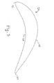
- trawl door 1 of the present invention is a "V" shaped trawl door, as evident to those ordinarily skilled in the art.
- a starboard side trawl door is shown but, as also evident to those ordinarily skilled in the art, there will be a corresponding port side trawl door.
- Each door includes main deflector body 2 formed by upper deflector body portion 3 and lower deflector body portion 4.
- Each of upper and lower deflector body portions 3 and 4 include a convex outer side 28 (see FIG. 3 ), concave inner side 29, trailing edge 30 and leading edge 31.
- each body portion 3 and 4 Disposed forward of each body portion 3 and 4 is a lift enhancing arrangement including upper forward leading slat 6 and upper forward trailing slat 7, as well as lower forward leading slat 8 and lower forward trailing slat 9.
- the slats may be formed, made and arranged in any fashion as know in the art.
- Trawl door 1 of the present invention includes conventional tow point connection hardware including towing warp connector 10 as well as upper and lower trawl net bridle connection rings 11 and 12, respectively.
- Towing warp connector 10 is attached to center tension bearing plate 14, which communicates tensional loads to upper and, lower bridle connection rings 11 and 12, respectively, that are located on upper and lower tension bearing plates 13 and 15, respectively, through a load and tension transmitting and carrying structure that is partially enclosed within upper and lower deflector bodies 3 and 4, respectively (see FIG. 2 ), as is described more fully below.
- Slats 5 preferably fit into slots (not shown) that are cut partially into tension bearing plates 13, 14 and 15, so as to act as "female ends” to the "male end” of any particular spoiler.
- the slots have a shape that accommodates the profile of any particular slat where it passes through any particular tension bearing plate 13, 14 or 15.
- the slats are kept in position by the remainder of the structure of the trawl door 1 of the present invention, which prevents the tension bearing plates 13, 14 and 15 from moving away from one another. Additionally, slats 5 may be welded into place, such as by spot welding.
- upper deflector lower load bearing end-plate 61 Located between upper deflector body 3 and center tension bearing plate 14 is upper deflector lower load bearing end-plate 61, while located between upper deflector body 3 and upper tension bearing plate 13 is upper deflector upper load bearing end-plate 62.
- lower deflector upper load bearing end-plate 64 located between lower deflector body 4 and lower tension bearing plate 15 is lower deflector lower load bearing end-plate 65.
- Bolts 26 permanently attach load bearing end-plates 61, 62, 64 and 65 to tension bearing plates 13 14 and 15, and may have their bolt heads welded into position after being thoroughly threaded into place.
- One or more of a series of weight plates 69 are optionally attached to the lower surface of lower tension bearing plate 15, where either one or more weight plates 69 may permanently be attached, or may temporarily be attached and include a variety quantities, sizes (especially differing in thickness) and/or a variety of masses so as to permit selectively adjusting the mass of weight at the bottom of trawl door 1 and thus the ballast aiding to maintain a vertical orientation of trawl door 1 during field operations.
- a deflector body of the present invention and/or deflector bodies of the present invention as represented by upper deflector body portion 3 are preferably formed with hollow internal load bearing members 20 (e.g. tubes) having walls 21 and extending from the upper surface 22 of the deflector body to the lower surface 23 of the deflector body.
- Flanges 17 are permanently affixed to the distal ends of hollow internal load bearing members 20 and include threaded holes 18. Flanges 17 are sunk into the synthetic portion of the deflector body so that exterior surfaces 19 of flanges 17 are seated flush with (e.g. are co-planar with) the upper and lower surfaces 22 and 23 of the deflector body.
- Plugs seal otherwise open ends of hollow internal load bearing members 20 proximal flanges 17, while not extending beyond flanges 17, so that hollow internal load bearing members 20 are closed to the ambient and/or external environment, thereby prohibiting entry of seawater into hollow internal load bearing members 20, thereby also generating increased trawl door buoyancy, as well as constant trawl door buoyancy at varying water depths.
- the load bearing members 20 and proximal flanges 17 are preferably made from a strong and rigid material, e.g. stainless steel or a suitable metal alloy that can be selected by the skilled person.
- flanges 17 disposed at the lower surface 23 of deflector body 3 are preferably permanently attached to upper deflector lower load bearing end-plate 61 by means of threaded bolts (not shown) being screwed and/or threaded into threaded holes 18.
- the threaded bolts (not shown) have a bolt head that is sunk into flanges 17 (such as by being sunk into an enlarged portion at the external end of threaded holes 18) so as not to protrude beyond the level of the exterior surface of upper deflector lower load bearing end-plate 61, and are fixedly welded into position, so as to prevent unscrewing of the bolts.
- flanges 17 disposed at upper surface 22 of deflector body 3 are likewise attached to upper deflector upper load bearing end-plate 62.
- towing forces generated by the propeller of the towing vessel are transmitted through the towing warps, to:
- a tension bearing frame and/or a load bearing frame 25 (see FIG. 1 ) is formed by the complex of interconnected towing warp connector 10; tension bearing plates 13, 14 and 15; load bearing end-plates 61, 62, 64 and 65; hollow internal tubes 20 having flanges 17 with bolts threaded into threaded bolt holes 18 and passing through and interconnectinglflanges 17 to load bearing end plates 61, 62, 64 and 65 and thus to tension bearing plates 13, 14 and 15, towing warp connector 10 and bridle connection rings 11 and 12.
- tension towing upon the trawl net may mainly transmit directly from towing warp connector 10, through central tension bearing plate 14 to a single bridle connection ring located along the aft portion of central tension bearing plate 14, and not shown.
- tension and other load forces are still transmitted along the remainder of the tension bearing frame, however such loads primarily originate from water resistance, impacts with the trawling vessel during field operations, as well as from stabilizer lines that may connect to upper and lower bridle rings 11 and 12, respectively.
- a polyamide chemically mixed with an elastomer in such a weight ratio of the polyamide to the elastomer as to create a fluid synthetic material that permits upon complete solidification of the synthetic material a solid synthetic structure that receives impacts fracture free is poured while in a fluid state Into an essentially uniformly heated hot mold of a predetermined shape of a deflector body.
- Presently preferred embodiments of the invention make use of nylon-elastomer copolymers made with reaction injection molding technology.
- Materials for such processing are available from Brüggeman Chemical KG (Heilbronn, Germany) sold under the trade name NYRIM®.
- NYRIM ® the Nylon and elastomer phases are chemically bounded.
- the chemically bounded but incompatible Nylon and elastomer blocks make a semi-crystalline material.
- the Nylon-6 properties are complemented with toughness and resilience from the elastomer blocks.
- NYRIM ® polymers are typically processed via RIM (Reaction Injection Molding) processing or casting. Nyrim can also be rotomolded.
- RIM processing is the preferred method to manufacture large, complex or thick parts. RIM processing allows for large design flexibility. Pressures are a little above atmospheric, resulting in lower mold and manufacturing costs. Glass fiber reinforcement or particulate mineral fillers can be used in Nyrim processing. NYRIM is formulated with elastomer contents from 7% (NYRIM 700) up tp 40% (NYRIM 4000).
- a synthetic material that is poured into the hot mold while in a fluid and/or liquid state is a nylon-precursor combined with an elastomer as well as a catalyst and/or polymerization additive(s) used for anionic polymerization of a lactame into Nylon.
- this mixture After pouring and when the temperatures of the mixture and the mold temperature are sufficiently hot this mixture reacts anionically to form a polymer that is a cast polymer, and when using caprolactam as a raw material this cast polymer is either a cast nylon or a cast "NYRIM".
- the polymerization of the raw materials causes the liquids to solidify into a polymer, and the anionic polymerization of the lactame into the Nylon results in a solid synthetic material for synthetic portions of the trawl door that receive impact fracture free.
- the polymer that is being formed is in a solid state because it only melts at temperatures above 220°C, and the temperatures during the reaction only get as hot as 205°C. That is, in the case of the above instant example of a reaction, the polymer that is being formed is in a solid state because it is formed by a reaction occurring at a temperature that is lower than the melting point of the polymer.
- Lactames that can be used for anionic polymerisation are, for example: caprolactam, laurinolactam, and mixtures of these two.
- the elastomer content of the nylon-elastomer mixture is in the range of 5-40%.
- the elastomer is up to twenty percent (20%) of the weight of the mixture making up the synthetic material including about 15% or about 20%, with from sixteen percent (16%) to eighteen percent (18%) being preferred, and most preferred being sixteen and seven tenths percent (16.7%), with eleven and one tenths percent (11.1%) as well useful.
- sixteen percent (16%) to eighteen percent (18%) being preferred, and most preferred being sixteen and seven tenths percent (16.7%), with eleven and one tenths percent (11.1%) as well useful.
- no elastomer is needed, or as little as two percent elastomer is needed, so long as the polymerization of the lactam into Nylon is an anionic polymerization.
- polystyrene resin may substitute the Nylon, depending upon experimental verification of the suitability of any particular polymeric substance.
- the polymerization be a cast polymerization.
- hollow internal load bearing tubes 20 having flanges 17 with threaded holes 18, already arranged, disposed and fixedly positioned within the hot mold so that after pouring in the fluid synthetic material capable of forming a Nylon chemically mixed with an elastomer, the synthetic material solidifies around and permanently encloses and incorporates hollow internal load bearing tubes 20 with flanges 17 having threaded holes 18. It is anticipated that a plate or plates may replace the tubes for portions of frame 25.
- a portion of the trawl door may be machined (including sculpted and/or carved) from a block of the solidified synthetic material. Automated carving using computer controlled machining equipment is preferred.
- a block of the solid synthetic material may be made by molding, even with void spaces inside of it to accommodate structure, any portion of frame 25, electronics or other tools, or to create void space for buoyancy. Then, the block may be machined into the desired shape of a portion of the trawl door, such as into the shape of one of the deflector's for use in the trawl door of the present invention.
- the present invention provides for:
- the present invention additionally provides for an improved method for producing the trawl door of the present invention wherein the step described in the above i mentioned method, of pouring into the mold cavity said liquid synthetic material capable of solidifying to form the solid synthetic material having the polymeric material mixed with the elastomeric material, includes the further step of selecting as the liquid synthetic material a material capable of solidifying to form solid synthetic material having as the polymeric material at least a polyamide, and preferably Nylon-6.
- Other polyamides such as the above mentioned may as well be used.
- Particularly preferred are mixtures of polymeric material (preferably polyamides) and an elastomer that become chemically bonded as a copolymer. Such mixtures are suitably as described above, e.g. with regard to type of polymer, elastomer and ratio of polymer to elastomer.
- the present invention additionally provides for an improved method for producing the trawl door of the present invention wherein the step described in the above mentioned method of pouring into the mold cavity containing the portion of the load bearing frame liquid synthetic material capable of solidifying to form the solid synthetic material having the polymeric material mixed with the elastomeric material includes the further step of selecting as the liquid synthetic material a material capable of solidifying to form solid synthetic material having as the polymeric material at least a polyamide, and preferably Nylon-6.
- Other polyamides may as well be used such as described above, and mixtures forming copolymers with elastomers, as described in detail above.
- the interior side of the mold corresponding to the convex outer side of the trawl door is made so as to maximize velocity of the layer of water such as by being as smooth as possible.
- the interior side of the mold corresponding to the concave inner side of the trawl door may be made rough or otherwise irregular so as to impede and slow down water flow, thereby increasing lift.
- at least the convex outer side of the trawl door's deflector(s) may as well be coated with a very low friction substance, including a low friction coating, Teflon or other material.
- the deflector body formed around the multiple hollow internal load bearing tubes 20 is unable to rotate relative to the complex of hollow internal load bearing tubes 20 forming a portion of the tension and/or load bearing frame 25 (see FIG. 2 ) encapsulated within the synthetic portion of the deflector body.
- a great variety of structures may be employed for the tension and/or load bearing frame encapsulated within the synthetic portion of a deflector body, so long as the shape of the encapsulated tension and/or load bearing frame 25 prevents its rotation or movement within and relative to the synthetic portion of the deflector body.
- the trawl door shown in FIG. 1 is a "V" door
- FIG. 3 shows to scale or essentially to scale a preferred profile 27 of a main deflector body of a trawl door 1 of the present invention, as used in the instant example of the trawl door of the present invention to form the profiles of upper and lower deflector bodies 3 and 4, respectively.
- the complete shape and teachings of the profile 27 shown in FIG. 3 are the same as the profile for that maximally efficient low-speed high-lift airfoil profile having its profile known by the name and/or code "NACA-338117" as found in the "VisualFoil Version 4.1" by Hanley Innovations (Ocala Florida, USA).
- NACA-338117 the profile for that maximally efficient low-speed high-lift airfoil profile having its profile known by the name and/or code "NACA-338117" as found in the "VisualFoil Version 4.1" by Hanley Innovations (Ocala Florida, USA).
- NACA-338117 the profile for that maximally efficient low-speed high-lift airfoil profile having
- profile 27 includes convex outer side 28, concave inner side 29, trailing edge 30 and leading edge 31.
- Trailing edge 30 is the most aft portion of any deflector body of the present invention as disposed in the trawl door of the present invention
- leading edge 31 is the most forward portion of any deflector body of the present invention as disposed in the trawl door of the present invention.
- the widest point of the profile 27 is approximately seventeen percent to eighteen percent (17% to 18%) of the length of the profiles chord, and is at least eleven percent (11%) of the length of the profiles chord, and is located front of center of the profile's chord.
- the widest point of the profile is located at a point along the profiles chord that corresponds to a distance that is front of center of the chord by at least three percent (3%) of the chord's length.
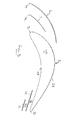
- a lift enhancing arrangement 5 disposed forward of the leading edge 31 of a main deflector body or any deflector body of the present invention, is a lift enhancing arrangement 5.
- at least one slat is employed with any main deflector body of the present invention having the profile taught hereinabove. None of the known art has suggested using slats in combination with a deflector body having a profile similar to the shape of the profile taught herein as most preferred for the shape of the profile of any main deflector body for use in a trawl door of the present invention.
- the upper forward leading slat 6 has a profile generally the same as the profile of the other side 28 of the body portion 3 at an area proximal the widest point of the profile 27 and is held spaced from the leading edge 31 by being fixed into the tension plates 13,14 with the leading edge 6a of the slat 6 in fine with the leading edge 31 of the body portion.
- the leading edge 6a of the slat 6 is spaced from the leading edge 31 by the same distance as the leading edge 6a is spaced from the widest point of the profile 27.
- the length of the slat 6 is such that it is above the top surface of the profile 27 and because of the differences in profile as between the slat 6 and the portion of the profile between its leading edge and the top of the profile 27, a slot is formed along the length of the leading edge 31.
- the slat diminishes in area as one moves from the leading edge 31 along the profile 27 and this formation channels water flowing through the slot to energise the boundary layer about the profile 27 and retain separation of the boundary layer which increases lift as explained previously.
- This slat 7 is located in the slot formed by the spoiler 6 and has a leading edge 7a in line with the leading edges 6a and 37 as well as a profile which is generally the same as the profile of the outer side 28 at an area defined as rearward of the leading edge 31 but forward of the widest point of the profile 27.
- the slat 7 thus divides the slot along the leading edge 31 into two which enhances the energisation of the boundary layer.
- the slat 7 is shorter than the slat 6 being about 50% of the length of the slat 6 and so does not extend above the top surface of the profile 27.
- Fig 5 also shows a modification which maybe made to the trawl door as shown in Fig 1 .
- This modification comprises the provision of a trailing edge lift enhancing structure in the form of one or more trailing edge slats 51 and 52 located under the profile 27 which form inner and outer trailing edge slots 53,54.
- the trailing edge slat or slats 51,52 are generally flat and extend along the length of the trailing edge 32 and are fixed to the tension plates 13,14. They lie generally parallel of the portion of the concave inner side 29 proximal the trailing edge 32 of the profile 27.
- the slat 51 is approximately half the length of the slat52 and their trailing edges 51a,51b are generally aligned with the trailing edge 32 of the profile 27.
- each body portion of the trawl door will be provided with the leading edge slat arrangement shown in Fig 5 and may be also provided with the trailing edge slat arrangement if desired. What is done for one trawl door is done to the other in order to generate stable conditions.
- Such a construction of a trawl door of the present invention has been shown to be useful in field operations when the angle of attack of the trawl door is 18 (eighteen) degrees, allowing much reduced drag.
- a trawl door construction also produces at least 15 (fifteen) percent greater efficiency than any other known trawl door constructions.
- the spoilers themselves may have profiles similar to that profile shown in FIG. 3 and 5 and may also be formed from a synthetic material that upon solidification forms a structure that receives impacts fracture free.
- the trawl door of the present invention provides for a new and useful method for varying the spreading force capable of being generated by a trawl door while simultaneously maintaining an optimal angle of attack for the trawl door, thus maintaining optimal hydrodynamic efficiency for any trawl door of the present invention while simultaneously varying the amount of spreading forces capable of being generated by such trawl door.
- trawl door 1 of the present invention has a lower trawl door portion 71 and an upper trawl door portion 72, whether it is a "V" door or otherwise, and whether or not it has a central tension bearing plate or like hardware, or otherwise.
- the lower and upper portions 71 and 72 each correspond to the lower and upper half of the particular trawl door.
- lower trawl door portion 71 is defined as including all structures taught and shown herein for trawl door 1 of the present invention that both include central tension bearing plate 14 and also are situated below central tension bearing plate 14, excepting towing warp connector 10, bridle connection ring 12 and weight plates 69, and may be of varying sizes and surface area.
- upper trawl door portion 72 includes all structures as taught and shown herein for trawl door 1 of the present invention that both include central tension bearing plate 14 and also are situated above central tension bearing plate 14, excepting towing warp connector 10 and bridle connection ring 11, and also may be of varying sizes and surface area.
- both lower and upper trawl door portions 71 and 72 would correspond to the general shape and structure of the entire trawl door, and may be of varying sizes so as to provide varying amounts of surface area.
- a modification in the form of trawl door extension pieces 81 are usefully temporarily attached to the top and bottom ends of trawl door 1, so as to increase the size of trawl door 1, and thus increase the amount of spreading force it is capable of generating.
- upper trawl door extension piece 83 is formed in a fashion essentially identical to upper trawl door portion 72, and includes upper trawl door extension piece deflector body 52, extension slats 87 and upper trawl door extension piece lower plate 85 that is essentially identical in form to center tension bearing plate 14 while performing the function both of upper tension bearing plate 13 as well as of upper deflector lower load bearing end-plate 61.
- Upper trawl door extension piece lower plate 85 attaches flush to the exterior surface of upper tension bearing plate 13 by means of bolts 90.
- Upper trawl door extension piece 83 also includes upper extension plate 93, which serves the function both of upper deflector upper load bearing end-plate 62 as well as the function, as far as providing a retention structure for extension spoilers 87, of upper tension bearing plate 13.
- lower trawl door extension piece 84 is formed in a fashion essentially identical to lower trawl door portion 71, and includes lower trawl door extension piece deflector body 53, extension spoilers 88 and lower trawl door extension piece upper plate 87 that is essentially identical in form to center tension bearing plate 14 while performing the function both of lower tension bearing plate 15 as well as of lower deflector upper load bearing end-plate 64.
- Lower trawl door extension piece upper plate 87 attaches flush to the exterior surface either of lower tension bearing plate 15 or of a weight plate 69 by means of bolts 90.
- Lower trawl door extension piece 84 also includes lower extension plate 94, which serves the function both of lower deflector lower load bearing end-plate 65 as well as the function of, as far as providing a retention structure for extension spoilers 88, of tower tension bearing plate 15.
- the upper and lower trawl door extension pieces 83, 85 may be formed with greater void spaces within their synthetic structures so as to create more buoyancy, and may be formed with a lesser quantity of hollow internal load bearing tubes 20, which may also lesser strengths and wall thicknesses, and/or of greater diameters so as to create more void spaces and buoyancy.
- trawl door 1 of the present invention includes a swept back leading edge, like a Delta wing, which is known as "wing shaped" in the trawl door industry
- the trawl door of the present invention may have a leading edge that only lies in one plane and is intended to be used with the trawl door's leading edge perpendicular or generally perpendicular to the water flow.
- the upper and lower trawl door extension pieces 83 and 85 also would have leading edges designed to be fished perpendicular or generally perpendicular to the oncoming water flow.
- trawl door extension pieces 83 and 85 may themselves have leading edges that are designed to be fished perpendicular or generally perpendicular to the, oncoming water flow, while the remainder of the trawl door 1 may be as shown in FIG. 1 , i.e. a "wing shaped" trawl door with "swept back" leading edges to its lower and upper trawl door portions 71 and 72, respectively.
- variable lift trawl door of the present invention also known as an extendable trawl door
- trawl doors of the present invention may have their surface area increased by adding one or more of trawl door extension pieces somewhere other than to the distal portions of the trawl door.
- one or more trawl door extension piece may be added to the center portion of the trawl door, such as by dividing center tension bearing plate 14 into two or three layers, separating the layers, and adding in between them either trawl door extension pieces 83, 85, or by adding just one trawl door extension piece.
- the trawl door extension pieces may be formed so as to telescope out from the remainder of the body of the trawl door, which such embodiment is most useful with trawl doors having deflector bodies and no spoilers.
- the present invention permits manufacture of a trawl door having a main deflector embodying the characteristics of a rather thick width, lightness in water and economy of manufacture, based upon the unexpected and heretofore unknown discovery that unlike usefulness for synthetics in other terrestrial and marine applications, in order for trawl doors usefully to be formed with their primary impact receiving structures employing a synthetic material, that such synthetic material must receive impacts fracture free.
- a Nylon chemically mixed with an elastomer (i.e. as a copolymer, e.g.
- a block or random copolymer as described in more detail above
- a block or random copolymer as described in more detail above
- the relative amounts of the Nylon and the elastomer may be adjusted experimentally, and should at least preclude formation of fractures on at least any portions of the trawl doors' exterior and/or impact bearing structures formed by the solid synthetic material.
- a mass ratio of 16.6% (sixteen and six tenths percent) by mass of an elastomer to a Nylon is preferred, with a mass ratio of from at least five percent to eighteen percent (5% to 18%) of the elastomer by mass relative to the Nylon being presently useful.
- a Nylon elastomer copolymer and sold under the trade name "NYRIM” is preferred.
- NYRIM 1500 is presently preferred for trawl doors of the present invention.
- Another synthetic substance possibly useful for the synthetic portions of trawl doors of the present invention is sold under the trade name "STAR-RIM". Both “NYRIM” and “STAR-RIM” are products of Bruggemann Chemical Company. Information on “NYRIM", how to use it, how to blend it, its properties and the like are provided by Brüggeman Chemical Co. and found on the company's internet websites www.NYRIM.com, and www.rimnylon.com.
- NYRIM and STAR-RIM are processed via RIM (Reaction Injection Molding) processing or casting.
- NYRIM can also be rotomolded. This may be done at low atmospheric pressures.
- AP-Caprolactam special grade of caprolactam that contains very low water content
- polymerization additives are used for anionic polymerization of caprolactam into (centrifugal) cast Nylon 6.
- a predetermined shape generally in the shape of a portion of the trawl door of the present invention, or of the entire trawl door of the present invention may be produced. As disclosed herein, any of these shapes may subsequently be machined to final dimensions.
- Brüggemann Chemical provides the following raw materials for the anionic polymerization mentioned above:
- a trawl door including at least one (1) spoiler disposed forward of the leading edge of at least a single main deflector body;
- a main deflector body having a cambered profile wherein the camber defined by the curvature of the main deflector's outer side from the leading edge to the trailing edge of the main deflector body is greater than the camber defined by the main curvature of the main deflector's inner side from the leading edge to the trailing edge of the main deflector body, generates more outwardly directed thrust per unit of resistance.
- a trawl door having at least one and preferably two slats disposed forward of (more proximal the oncoming water flow) a single main deflector body, and wherein said main deflector body has a profile wherein:
- the synthetic material that receives impacts fracture free be a thermoplastic that is capable of being poured into a mold, such as a hot mold.
- a mold such as a hot mold.
- the entire trawl door may be molded at one time.
- the towing points connection hardware 10, 11 and 12 be conventional metallic hardware that is attached to a tension and/or load bearing metallic frame that itself is situated within the mold in such a way that the thermoplastic is poured around and about such connection hardware incorporating tension bearing metallic frame, and subsequently solidifies around the structure of the frame.
- the frame should be shaped so as to distribute over a maximal area of the synthetic structure any torque or other forces applied between the metallic frame and the synthetic portion of the trawl door and/or main deflector body.
- molds in the shape of a portion of the trawl door for use in manufacturing trawl doors of the present invention, such as in the shape of a deflector body of the trawl door, may leave imperfections and/or flaws upon the surface of the portion of the trawl door being formed by the mold upon solidification of the synthetic material. These flaws are readily removed by known methods.
- a mold is referred to as having the shape of a portion of trawl door 1, it is intended to include molds having generally a shape of a portion of the trawl door of the present invention.
- the conventional metallic tow point hardware may be bolted to the finished main deflector body, or other substantial portion of the molded trawl door, the tensile bearing structure is formed from the synthetic.
- the positioning of the conventional tow points connection hardware may be calculated and oriented using any of a variety of methods widely known to those skilled in the art.
- electronic or mechanical hardware including controls and power driven actuator for changing the orientation of the towing warp connector 10 relative to the remainder of trawl door 1
- electronic or mechanical hardware may be enclosed inside the synthetic structure of the trawl door.
- electrical, mechanical or other hardware may be placed into a desired location within the hot mold prior to the pouring of the synthetic, thus becoming encapsulated by the synthetic, and being permanently contained within the synthetic structure of the trawl door.
- hollow cavities or cavities filled with a light foam may be formed into the synthetic structures of the trawl door of the present invention by, for example, placing a foam block within the hot mold prior to pouring in the synthetic mixture. Or an empty hollow container of a certain shape may be placed within the hot mold prior to the pouring in of the synthetic mixture.
- void spaces may be created by rotomolding or by use of lost core technology in RIM.
- the present invention further provides for a trawl door as described above wherein those synthetic portions of the trawl door that receive impacts fracture free include exterior structures of the trawl door.
- the present invention provides for a trawl door as described above wherein the polymeric material used to form synthetic portions of the trawl door includes a Nylon.
- the trawl door of embodiment 1 wherein synthetic portions of the trawl door that receive impacts fracture free include exterior structures of the trawl door.
- polyamide is selected from the group consisting of Nylon 6; Nylon 9; Nylon 6,6; Nylon 6,9; Nylon 6,10; Nylon 6,12; Nylon 4,6; Nylon 12 and any mixture thereof.
- the elastomer is selected from the group consisting of polyolefins including polyethylene (ethylene homopolymer), ethylene/alpha-olefin interpolymers, alpha-olefin homopolymers, such as polypropylene(propylene homopolymer), and alpha-olefin interpolymers; polyamines including polybutadiene diamine, polybutadiene polyamines and butadiene-acrylonitrile polyamines, polyether polyamines are poly(oxybutylene)diamine, poly(oxyethylene)diamine, poly(oxypropylene)diamine, poly(oxypropylene)triamine, poly(oxypropylene)tetramine and combinations thereof such as, for example, block copolymers of poly(oxypropylene) and poly(oxyethylene) with at least two functional amine groups.
- polyolefins including polyethylene (ethylene homopolymer), ethylene/alpha-olefin interpolymers, alpha-olefin
- said exterior structure synthetic portions of the trawl door comprise at least one deflector body which comprises exterior portions formed from said synthetic material, said deflector body having a convex outer side and a concave inner side and comprising an internal support structure which form part of a load bearing frame.
- a trawl door including at least one deflector body and at least one lift enhancing arrangement, the at least one lift enhancing arrangement being disposed forward of the at least one deflector body, the deflector body having a profile comprising:
- the trawl door of any of embodiments 16-22 wherein synthetic portions of the trawl door that receive impacts fracture free include exterior structures of the trawl door.
- polyamide is selected from the group consisting of Nylon 6; Nylon 9; Nylon 6,6; Nylon 6,9; Nylon 6,10; Nylon 6,12; Nylon 4,6; Nylon 12 and a mixture thereof.
- the trawl door of embodiment 21 wherein the ratio of the polyamide to the elastomer includes at least sixteen percent by weight of elastomer.
- the trawl door of embodiment 21 wherein the ratio of the polyamide to the elastomer includes at least eighteen percent by weight of elastomer.
- deflector body comprises said portions from said synthetic material, and said deflector body comprises an internal support structure which form part of a load bearing frame.
- a trawl door comprising at least one trawl door extension piece, whereby trawl door size and spreading forces are able to be varied by deployment of the at least one trawl door extension piece.
- the trawl door of any of embodiments 34-39 comprising exterior structures of the trawl door from synthetic material comprising a polymeric material mixed with an elastomeric material.
- a trawl door according to any one of embodiments 16 to 42, wherein the lift enhancing arrangement comprises a slat having a profile generally the same as the profile of the outer side of the main deflector body at an area proximal the thickest point of the main deflector body.
- a trawl door according to embodiment 43 wherein the slat has a leading edge and a profile length such that a trailing edge of the slat projects above the profile.
- a trawl door according to embodiment 45 wherein the further slat has a profile the same as the profile of the outer side of the main deflector body at an area rearward of the leading edge of the main deflector body but forward of the thickest point of the main deflector body.
- a trawl door according to embodiment 46 wherein the slat has a leading edge which is in line with the leading edges of the slat and main deflector body respectively.
- a trawl door according to any one of embodiments 43 to 49 wherein the main deflector body is provided with at least one trailing edge slat located at the trailing edge of the profile adjacent the concave inner side.
- a trawl door according to embodiment 51 wherein the trailing edge of the at least one slat is aligned with the trailing edge of the profile.
- a trawl door according to embodiment 53, wherein the distal slat is half the length of the proximal slat.
- An improved method for producing a trawl door using synthetic materials comprising steps selected from a group consisting of:
- the method of embodiment 55 wherein the step of situating into the mold cavity the liquid synthetic material capable of solidifying to form the solid synthetic material having the polymeric material mixed with the elastomeric material includes the further step of selecting as the liquid synthetic material a material capable of solidifying to form solid synthetic material having as the polymeric material at least a polyamide.
- the method of embodiment 56 wherein the step of pouring into the mold cavity containing the portion of the load bearing frame the liquid synthetic material capable of solidifying to form the solid synthetic material having the polymeric material mixed with the elastomeric material includes the further step of selecting as the liquid synthetic material a material capable of solidifying to form solid synthetic material having as the polymeric material at least a polyamide.
- the method of embodiment 58 wherein the step of pouring into the mold cavity the liquid synthetic material capable of solidifying to form the solid synthetic material having the polymeric material mixed with the elastomeric material includes the further step of selecting as the liquid synthetic material a material capable of solidifying to form solid synthetic material having as the polymeric material at least Nylon-6.
- the method of embodiment 56 wherein the step of pouring into the mold cavity containing the portion of the load bearing frame the liquid synthetic material capable of solidifying to form the solid synthetic material having the polymeric material mixed with the elastomeric material includes the further step of selecting as the liquid synthetic material a material capable of solidifying to form solid synthetic material having as the polymeric material at least a Nylon-6.
Landscapes
- Life Sciences & Earth Sciences (AREA)
- Environmental Sciences (AREA)
- Animal Husbandry (AREA)
- Biodiversity & Conservation Biology (AREA)
- Securing Of Glass Panes Or The Like (AREA)
- Holders For Sensitive Materials And Originals (AREA)
Applications Claiming Priority (4)
| Application Number | Priority Date | Filing Date | Title |
|---|---|---|---|
| IS7371A IS2228B (is) | 2004-07-26 | 2004-07-26 | Toghleri með lága þyngd og minna togviðnám og aðferðir til að framleiða hann |
| US59853204P | 2004-08-02 | 2004-08-02 | |
| IS7514 | 2004-10-20 | ||
| EP05759016A EP1778006A2 (de) | 2004-07-26 | 2005-07-18 | Geformtes leichtes hochgeschwindigkeits-scherbrett mit erhöhter hydrodynamischer leistung und verwendungs- und herstellungsverfahren |
Related Parent Applications (1)
| Application Number | Title | Priority Date | Filing Date |
|---|---|---|---|
| EP05759016.8 Division | 2005-07-18 |
Publications (1)
| Publication Number | Publication Date |
|---|---|
| EP2238831A1 true EP2238831A1 (de) | 2010-10-13 |
Family
ID=34972033
Family Applications (2)
| Application Number | Title | Priority Date | Filing Date |
|---|---|---|---|
| EP05759016A Withdrawn EP1778006A2 (de) | 2004-07-26 | 2005-07-18 | Geformtes leichtes hochgeschwindigkeits-scherbrett mit erhöhter hydrodynamischer leistung und verwendungs- und herstellungsverfahren |
| EP10169271A Withdrawn EP2238831A1 (de) | 2004-07-26 | 2005-07-18 | Schnelles, leichtgewichtiges, geformtes Scherbrett mit verbesserter hydrodynamischer Effizienz und Verfahren zur Verwendung und Herstellung |
Family Applications Before (1)
| Application Number | Title | Priority Date | Filing Date |
|---|---|---|---|
| EP05759016A Withdrawn EP1778006A2 (de) | 2004-07-26 | 2005-07-18 | Geformtes leichtes hochgeschwindigkeits-scherbrett mit erhöhter hydrodynamischer leistung und verwendungs- und herstellungsverfahren |
Country Status (4)
| Country | Link |
|---|---|
| US (1) | US20080307691A1 (de) |
| EP (2) | EP1778006A2 (de) |
| CA (1) | CA2573419A1 (de) |
| WO (1) | WO2006011163A2 (de) |
Families Citing this family (20)
| Publication number | Priority date | Publication date | Assignee | Title |
|---|---|---|---|---|
| IS2635B (is) * | 2007-11-20 | 2010-06-15 | Hampidjan Hf | Endurbættur toghleri |
| LT2182797T (lt) * | 2007-07-31 | 2017-07-10 | Thyboron Skibssmedie A/S | Didelio stabilumo, didelio efektyvumo tralo lenta |
| KR101099649B1 (ko) * | 2009-02-27 | 2011-12-29 | 주식회사 비엠인터내셔널 | 표층용 트롤 전개판 |
| US20120174464A1 (en) * | 2009-09-14 | 2012-07-12 | Sherif Safwat | High efficiency, high stability, multi-elevation trawl door and methods |
| WO2011135006A1 (en) | 2010-04-27 | 2011-11-03 | Hampidjan Hf | Perforated trawl door and methods |
| CN103283691B (zh) * | 2013-06-13 | 2014-12-10 | 中国水产科学研究院东海水产研究所 | 一种小展弦比矩形双弧面表中层网板及其浮沉力调节方法 |
| KR101733102B1 (ko) * | 2015-07-08 | 2017-05-24 | 주식회사 비엠인터내셔널 | 트롤 전개판 |
| US10925267B2 (en) * | 2015-09-14 | 2021-02-23 | Ny Toghlerahonnun Ehf. | Airfoil shaped trawl door |
| WO2017046819A1 (en) * | 2015-09-14 | 2017-03-23 | Ny Toghlerahonnun Ehf. | Hollow trawl door and weights therefor |
| WO2017046821A1 (en) * | 2015-09-14 | 2017-03-23 | Ny Toghlerahonnun Ehf. | Trawl door and novel connection therefor |
| PT3376858T (pt) * | 2015-11-18 | 2023-01-19 | Mld Aps | Porta de arrasto com meio de regulação |
| ES2724350T3 (es) * | 2015-12-22 | 2019-09-10 | Volu Ventis Aps | Puerta de arrastre con intensificador de flujo para capacidad de sustentación aumentada |
| CN105875534B (zh) * | 2016-05-24 | 2019-05-31 | 中国水产科学研究院东海水产研究所 | 一种框架嵌板式组合网板 |
| CN106719483A (zh) * | 2016-12-12 | 2017-05-31 | 中国海洋大学 | 单船拖网半柔性可折叠矩形“v”型网板 |
| DK179265B1 (en) * | 2016-12-29 | 2018-03-19 | Mld Aps | TRAWL BOWL TO TOUCH AFTER A SHIP |
| CA2988743A1 (en) * | 2017-12-13 | 2019-06-13 | Fisheries And Marine Institute Of The Memorial University | Multi-kite apparatus for use with bottom trawls |
| GB201811369D0 (en) * | 2018-07-11 | 2018-08-29 | Josafatsson Atli Mar | A spreading device |
| WO2020084643A1 (en) | 2018-10-26 | 2020-04-30 | Ny Toghlerahonnun Ehf. | Connection for a trawl door |
| GB202005885D0 (en) * | 2020-04-22 | 2020-06-03 | Josafatsson Atli Mar | Spreading device |
| US11751551B2 (en) * | 2021-04-15 | 2023-09-12 | Bradley David Cahoon | Hydrofoil fishing lure apparatus |
Citations (10)
| Publication number | Priority date | Publication date | Assignee | Title |
|---|---|---|---|---|
| DE562243C (de) | 1932-10-22 | Wilhelm Soehle | Scherbrett mit zwischen Rahmenteilen kulissenartig angeordneten Einzelscherbrettern | |
| US3190025A (en) | 1963-07-05 | 1965-06-22 | Burney Charles Dennistoun | Trawling otters |
| US4180935A (en) | 1977-08-29 | 1980-01-01 | Massachusetts Institute Of Technology | Hydrofoil trawl door |
| US4590243A (en) | 1982-05-04 | 1986-05-20 | Monsanto Company | Process for the preparation of nylon block polymers |
| US4617355A (en) | 1984-06-21 | 1986-10-14 | Dsm Rim Nylon Vof | Cross-linked nylon block copolymers |
| US4640037A (en) | 1982-03-02 | 1987-02-03 | Ashworth John F H | Trawl doors |
| WO1994017124A1 (en) | 1993-01-27 | 1994-08-04 | Dsm N.V. | Process for the preparation of a nylon block copolymer |
| WO1998024685A1 (en) * | 1996-12-06 | 1998-06-11 | Petroleum Geo-Services As | System for towing equipment at sea |
| US6131327A (en) * | 1996-04-30 | 2000-10-17 | Larsen; Helgi | Otter board |
| WO2001084922A1 (en) | 2000-05-09 | 2001-11-15 | Devol Engineering Limited | Trawl door |
Family Cites Families (32)
| Publication number | Priority date | Publication date | Assignee | Title |
|---|---|---|---|---|
| US2942371A (en) * | 1957-10-04 | 1960-06-28 | Canadian Patents Dev | Dual-purpose midwater-bottom otterboard |
| US3079720A (en) * | 1959-01-22 | 1963-03-05 | Suberkrub Franz | Otter boards for trawl nets |
| US3308568A (en) * | 1966-06-29 | 1967-03-14 | Frank J Luketa | Polyhedral trawl door |
| US3705074A (en) * | 1971-05-21 | 1972-12-05 | Allied Chem | High bulk yarn formable mixtures of linear polymeric thermoplastic materials |
| SU551019A1 (ru) * | 1973-01-03 | 1977-03-25 | Мурманское Отделение Государственного Проектно-Конструкторского Института Рыбопромыслового Флота "Гипрорыбфлот" | Приспособление дл раскрыти усть трала |
| US3890771A (en) * | 1973-01-19 | 1975-06-24 | Thomas G Kelpin | Aquatic harvester with improved flotation system |
| US4130078A (en) * | 1975-01-06 | 1978-12-19 | Institut Francais Du Petrole | Floating device connected to a ship, for towing a submerged member with a lateral shift thereof with respect to the ship route |
| GB2129661B (en) * | 1982-10-15 | 1986-03-26 | Thomas Horsfield | A trawl board |
| US4653213A (en) * | 1985-03-27 | 1987-03-31 | May Billy D | Low resistance net-supporting frame assembly |
| GB8509032D0 (en) * | 1985-04-09 | 1985-05-15 | Ashworth J F H | Trawl doors |
| US4890568A (en) * | 1988-08-24 | 1990-01-02 | Exxon Production Research Company | Steerable tail buoy |
| US4893947A (en) * | 1989-01-23 | 1990-01-16 | Hurley Robert E | Spinning machine rotor shaft disk |
| SU1687186A1 (ru) * | 1989-06-19 | 1991-10-30 | Литовское Производственное Объединение Рыбной Промышленности "Литрыбпром" | Распорна тралова доска |
| JPH0488260U (de) * | 1990-12-06 | 1992-07-31 | ||
| JP2731472B2 (ja) * | 1991-11-12 | 1998-03-25 | パシフィック、デパートメント、オブ、パースペクティブ、サイエンティフィック、フッシャーリング、リサーチ(ターニフ) | トロール漁具およびトロール漁法 |
| US5265367A (en) * | 1991-11-13 | 1993-11-30 | Nichimo Co., Ltd. | Otter board |
| US5267408A (en) * | 1991-11-13 | 1993-12-07 | Nichimo Co., Ltd. | Otter board |
| CH684592A5 (de) * | 1992-02-05 | 1994-10-31 | Swil Technik Ag | Kunststoffspule für ein Wickelgut. |
| US5341591A (en) * | 1992-07-16 | 1994-08-30 | Hicks Carl E | Planer board |
| GB9325937D0 (en) * | 1993-12-18 | 1994-02-23 | Dixon James L | Improvements in or relating to fishing apparatus |
| US5555817A (en) * | 1994-07-01 | 1996-09-17 | Standard Car Truck Company | Pad of substantially rigid synthetic resin for a friction wedge in a bolster pocket |
| FR2735442B1 (fr) * | 1995-06-13 | 1997-09-05 | Ifremer | Procede et plan porteur pour faire diverger un corps remorque |
| US6234102B1 (en) * | 1996-12-06 | 2001-05-22 | Petroleum Geo-Services As | Deflector |
| US6286574B1 (en) * | 1997-10-30 | 2001-09-11 | Hutchinson | Device for motor vehicle running flat and method for mounting |
| US6532189B2 (en) * | 2000-11-30 | 2003-03-11 | Westerngeco L.L.C. | Curved float for marine divertors |
| US20050155271A1 (en) * | 2002-09-09 | 2005-07-21 | Holy Norman L. | Whale-safe rope |
| JP4054736B2 (ja) * | 2003-09-01 | 2008-03-05 | 有限会社よつあみ | 自己融着糸条の製造方法 |
| US20050150152A1 (en) * | 2003-12-29 | 2005-07-14 | Holy Norman L. | Whale safe groundline |
| EP1819218B1 (de) * | 2004-11-04 | 2011-10-05 | Hampidjan HF. | Pelagische scherbrettkonstruktion und verfahren |
| US20060143973A1 (en) * | 2004-12-30 | 2006-07-06 | Corbitt Newsome E Iii | Bait saving hook with resilient bait guard |
| US7499373B2 (en) * | 2005-02-10 | 2009-03-03 | Westerngeco L.L.C. | Apparatus and methods for seismic streamer positioning |
| US7404370B2 (en) * | 2006-08-02 | 2008-07-29 | Pgs Norway Geophysical As | Steerable diverter for towed seismic streamer arrays |
-
2005
- 2005-07-18 EP EP05759016A patent/EP1778006A2/de not_active Withdrawn
- 2005-07-18 CA CA002573419A patent/CA2573419A1/en not_active Abandoned
- 2005-07-18 WO PCT/IS2005/000016 patent/WO2006011163A2/en active Search and Examination
- 2005-07-18 EP EP10169271A patent/EP2238831A1/de not_active Withdrawn
- 2005-07-18 US US11/658,479 patent/US20080307691A1/en not_active Abandoned
Patent Citations (10)
| Publication number | Priority date | Publication date | Assignee | Title |
|---|---|---|---|---|
| DE562243C (de) | 1932-10-22 | Wilhelm Soehle | Scherbrett mit zwischen Rahmenteilen kulissenartig angeordneten Einzelscherbrettern | |
| US3190025A (en) | 1963-07-05 | 1965-06-22 | Burney Charles Dennistoun | Trawling otters |
| US4180935A (en) | 1977-08-29 | 1980-01-01 | Massachusetts Institute Of Technology | Hydrofoil trawl door |
| US4640037A (en) | 1982-03-02 | 1987-02-03 | Ashworth John F H | Trawl doors |
| US4590243A (en) | 1982-05-04 | 1986-05-20 | Monsanto Company | Process for the preparation of nylon block polymers |
| US4617355A (en) | 1984-06-21 | 1986-10-14 | Dsm Rim Nylon Vof | Cross-linked nylon block copolymers |
| WO1994017124A1 (en) | 1993-01-27 | 1994-08-04 | Dsm N.V. | Process for the preparation of a nylon block copolymer |
| US6131327A (en) * | 1996-04-30 | 2000-10-17 | Larsen; Helgi | Otter board |
| WO1998024685A1 (en) * | 1996-12-06 | 1998-06-11 | Petroleum Geo-Services As | System for towing equipment at sea |
| WO2001084922A1 (en) | 2000-05-09 | 2001-11-15 | Devol Engineering Limited | Trawl door |
Non-Patent Citations (1)
| Title |
|---|
| ARNASON HARALDUR: "SPUTNIK - Yet another new model of Poly-Ice trawl doors", INTERNET CITATION, 1 December 2001 (2001-12-01), pages 1 - 8, XP002587987, Retrieved from the Internet <URL:http://www.hampidjan.is/media/PDF/Pokahorn2001_Enska.PDF> [retrieved on 20100621] * |
Also Published As
| Publication number | Publication date |
|---|---|
| EP1778006A2 (de) | 2007-05-02 |
| WO2006011163A2 (en) | 2006-02-02 |
| WO2006011163A9 (en) | 2006-05-11 |
| WO2006011163A3 (en) | 2006-03-23 |
| US20080307691A1 (en) | 2008-12-18 |
| CA2573419A1 (en) | 2006-02-02 |
Similar Documents
| Publication | Publication Date | Title |
|---|---|---|
| EP2238831A1 (de) | Schnelles, leichtgewichtiges, geformtes Scherbrett mit verbesserter hydrodynamischer Effizienz und Verfahren zur Verwendung und Herstellung | |
| US20080271356A1 (en) | Higher Efficiency Pelagic Trawl Door Construction Employing Universally Available Materials and Method | |
| CN1086544C (zh) | 网板 | |
| WO2007044859A2 (en) | Frame for a molded trawl door | |
| AU2016325115B2 (en) | Airfoil shaped trawl door | |
| RU2346433C2 (ru) | Легкая формованная распорная доска трала для высокоскоростного траления, обладающая повышенной гидродинамической эффективностью, способы ее использования и изготовления | |
| US20100000461A1 (en) | Foil shapes for use in barge skegs and marine propeller shrouds | |
| US20070193494A1 (en) | Modular Construction System For Floating Structures Such As Boats | |
| EP0734202A1 (de) | Verbesserungen an angelgeräten | |
| KR101288731B1 (ko) | 3 층 회전 성형된 모터 보트 | |
| CN2866321Y (zh) | 环保型全塑救生艇 | |
| CN206968943U (zh) | 一种水上漂浮体材料 | |
| WO2010098675A1 (en) | Float element | |
| CN110562384A (zh) | 一种轻型漂浮推进船体 | |
| CN215590942U (zh) | 一种双层滚塑舢板 | |
| CN217649604U (zh) | 一种用于海上液货输送的引缆浮标 | |
| US20230148260A1 (en) | Spreading Device | |
| BE1029866B1 (nl) | Aflandige zonnevlotter module | |
| CN209382215U (zh) | 一种水上休闲娱乐垂钓平台 | |
| KR102454537B1 (ko) | 스컬 겸용 카누 | |
| CN214985894U (zh) | 一种抗风浪双体甲板设备运输船 | |
| CN219619337U (zh) | 一种安全耐用的新型pc透明划艇 | |
| CN2351367Y (zh) | 防翻倒安全多用小船 | |
| KR20210114387A (ko) | 항해 중 전진에 대한 저항을 감소시키는 회전하는 회전체의 직렬 배열에 의해 형성된 수송용 부체 구조물 | |
| AU2008202040A1 (en) | Improved boat hull |
Legal Events
| Date | Code | Title | Description |
|---|---|---|---|
| PUAI | Public reference made under article 153(3) epc to a published international application that has entered the european phase |
Free format text: ORIGINAL CODE: 0009012 |
|
| AC | Divisional application: reference to earlier application |
Ref document number: 1778006 Country of ref document: EP Kind code of ref document: P |
|
| AK | Designated contracting states |
Kind code of ref document: A1 Designated state(s): AT BE BG CH CY CZ DE DK EE ES FI FR GB GR HU IE IS IT LI LT LU LV MC NL PL PT RO SE SI SK TR |
|
| RTI1 | Title (correction) |
Free format text: TRAWL DOOR |
|
| STAA | Information on the status of an ep patent application or granted ep patent |
Free format text: STATUS: THE APPLICATION IS DEEMED TO BE WITHDRAWN |
|
| 18D | Application deemed to be withdrawn |
Effective date: 20101014 |