EP2238424B1 - Differentielles vergleichendes drucküberwachungssystem - Google Patents
Differentielles vergleichendes drucküberwachungssystem Download PDFInfo
- Publication number
- EP2238424B1 EP2238424B1 EP08852663.7A EP08852663A EP2238424B1 EP 2238424 B1 EP2238424 B1 EP 2238424B1 EP 08852663 A EP08852663 A EP 08852663A EP 2238424 B1 EP2238424 B1 EP 2238424B1
- Authority
- EP
- European Patent Office
- Prior art keywords
- circuit
- fluidic
- cavity
- pressure
- fluid flow
- Prior art date
- Legal status (The legal status is an assumption and is not a legal conclusion. Google has not performed a legal analysis and makes no representation as to the accuracy of the status listed.)
- Active
Links
Images


Classifications
-
- G—PHYSICS
- G01—MEASURING; TESTING
- G01M—TESTING STATIC OR DYNAMIC BALANCE OF MACHINES OR STRUCTURES; TESTING OF STRUCTURES OR APPARATUS, NOT OTHERWISE PROVIDED FOR
- G01M3/00—Investigating fluid-tightness of structures
- G01M3/02—Investigating fluid-tightness of structures by using fluid or vacuum
- G01M3/26—Investigating fluid-tightness of structures by using fluid or vacuum by measuring rate of loss or gain of fluid, e.g. by pressure-responsive devices, by flow detectors
- G01M3/32—Investigating fluid-tightness of structures by using fluid or vacuum by measuring rate of loss or gain of fluid, e.g. by pressure-responsive devices, by flow detectors for containers, e.g. radiators
- G01M3/3236—Investigating fluid-tightness of structures by using fluid or vacuum by measuring rate of loss or gain of fluid, e.g. by pressure-responsive devices, by flow detectors for containers, e.g. radiators by monitoring the interior space of the containers
- G01M3/3263—Investigating fluid-tightness of structures by using fluid or vacuum by measuring rate of loss or gain of fluid, e.g. by pressure-responsive devices, by flow detectors for containers, e.g. radiators by monitoring the interior space of the containers using a differential pressure detector
-
- G—PHYSICS
- G01—MEASURING; TESTING
- G01M—TESTING STATIC OR DYNAMIC BALANCE OF MACHINES OR STRUCTURES; TESTING OF STRUCTURES OR APPARATUS, NOT OTHERWISE PROVIDED FOR
- G01M3/00—Investigating fluid-tightness of structures
- G01M3/02—Investigating fluid-tightness of structures by using fluid or vacuum
- G01M3/26—Investigating fluid-tightness of structures by using fluid or vacuum by measuring rate of loss or gain of fluid, e.g. by pressure-responsive devices, by flow detectors
Definitions
- the present invention relates to a differential comparative pressure monitoring system for monitoring the integrity of a component or structure.
- Applicant has developed numerous systems, devices and methods for structural integrity monitoring and structural health monitoring which may be used for example to detect and/or monitor the propagation of, cracks or other faults on or in a component or structure. Examples of such systems, devices and methods are the subject of various patents including US 5770794 ; US 6539776 ; US 6591661 ; US 6715365 ; and US 6720882 .
- EP 0518758 (Renault Automation) describes a method and device for checking the quality of a mechanical assembly consisting of components between which exists a mounting play in which a pneumatic leak may be created from one end of the assembly offering a surface with which it is possible to produce a temporary leak-tight connection, consisting in detecting the equilibrium position of a movable element, two opposed faces of which are subjected respectively to the pressure present in a chamber situated upstream from the connecting surface and to that present in a chamber situated upstream from a reference assembly.
- JPS 59 131138 Komei Kogyo describes the use of a manufacturing line as it is to inspect the presence of cracking of defective white tiles, individually and mechanically, with high precision and to select the defective white tiles while maintaining a manufacturing line speed by providing a stage wherein white tiles are conveyed by a conveyor after a drying process, a stage for air leak inspection, and a stage wherein only defective white tiles which cause an air leak are removed from a conveyor route.
- US 5367797 describes a method of establishing that pressure-influencing factors other than leakage of gas have stabilized before testing the integrity of a vessel in a system including the vessel, a reference vessel that can be connected to and isolated from the vessel, a common source of pressurized gas, a gauge to measure the difference between the vessel pressure and the reference vessel pressure and a computer capable of recording a series of pressure-difference measurements and mathematically manipulating them, the method including equalizing the pressures in the two vessels, then isolating them from each other for a preselected time period, then recording the pressure difference between them at the end of the time period, again equalizing the pressures and repeating that sequence until the pressure difference at the end of two consecutive time intervals is the same, thereby establishing that pressure-influencing factors other than leakage have stabilized.
- JPS6182138(A ) Honda Motor Co
- JPS6182138(A ) Honda Motor Co
- US4686638 Furuse Akio ) describes a method in which a predetermined number of preceding data items, which are obtained through measurement of change in pressure or pressure difference with respect to respective objects inspected and decided to be acceptable, are grouped according to types of the objects and stored in different storage regions. Each time new data is stored, the oldest data in the corresponding storage region is erased. An average of data stored in a designated storage region is computed and each object is decided if it is acceptable or not on the basis of the difference between the newly measured data of the object and the computed average of the data in the designated storage region corresponding to the object.
- Furuse Akio discloses a leak test method and apparatus which introduces high-pressure gas into a work and a master from a high-pressure gas source through first and second electromagnetic valves respectively, closes the first and second electromagnetic valves, detects the pressure difference between the work and the master by a differential pressure sensor, and compares the amount of leakage, obtained from the pressure difference, with a leakage reference value to thereby decides the work to be leak-free or leaky, a third electromagnetic valve is provided which permits and inhibits the passage of gas between the work and the master.
- the third electromagnetic valve Prior to measuring pressure difference variations in a measurement period and a stabilization period, the third electromagnetic valve is opened to establish a pressure equilibrium between the work and the master, then the electromagnetic valve is closed, then measures the pressure difference variations, and a last pressure difference variation ⁇ Pe is subtracted from an initial pressure difference variation ⁇ P s to obtain the amount of drift.
- US4979390 (Schupack Morris) describes an apparatus for testing the relative permeability of materials, particularly concrete structures, comprises a transparent, optically non-distorting head having a gasket, which together with the head defines a head chamber, and which allows the head to be sealed against the structure when a partial vacuum is induced in the head chamber.
- the decay of the vacuum may be measured, and the rate of decay provides an index of permeability.
- a liquid may be applied to the surface being tested and will foam to allow identification of cracks and fissures.
- a fluid is introduced into a secondary chamber defined by a secondary gasket and the head, and the rate of permeation of the fluid into the structure provides a measure of permeability.
- the vacuum mounted test apparatus allows in-situ testing without requiring the extraction of sample cores from the structure or making invasive attachments to the structure, thus providing a quality control apparatus and method for rapid testing of construction materials.
- the present invention arises from further development by Applicant in the above field of technology.
- One aspect of the present invention provides a differential comparative pressure monitoring system for monitoring of structural integrity of a component or structure, the system comprising,
- the reference circuit may comprise a reference cavity having characteristics substantially matched to the first cavity.
- the first cavity and the reference cavity may be substantially co-located.
- the first cavity and the reference cavity are formed in the sensor element.
- the sensor element is provided with a first surface that is sealed to the surface of the structure or component and a second opposite surface, wherein a first groove or channel is formed in the first surface, the first groove or channel forming the first cavity when the first surface is sealed to the structure or component; and, wherein the reference cavity is provided internal of the first and second surfaces of the sensor element.
- the sensor element may be formed as a laminate structure having a first layer which comprises the first surface and in which the first groove or channel is formed and a second layer seal onto the first layer on a surface opposite the first surface, wherein second layer comprises the second opposite surface and the reference cavity is formed between the first and second layers.
- the reference cavity is formed in a reference sensor element separate to the sensor element.
- the first fluidic circuit may comprise a first high fluid flow impedance connected in series between the pressure source and the first cavity.
- the reference circuit comprises a reference high fluid flow impedance connected in series between the pressure source and the reference cavity.
- the first and reference high fluid flow impedances may be formed to have substantially identical impedance to fluid flow.
- the first and reference fluidic circuits may be configured to extend substantially adjacent to each other.
- the system may further comprise a second fluidic circuit, the second fluidic circuit in fluidic communication with a second pressure source having a second pressure that is different to a first pressure of the first pressure source.
- the first pressure is negative relative to the second pressure.
- the second circuit may comprise a second groove or channel formed in the sensor element which, when the sensor element is sealed to the surface of the structure or component forms a second cavity adjacent to but sealed from the first cavity.
- the first and second cavities may be arranged to have matched fluidic characteristics. Furthermore the first and second fluidic circuits may have matched fluidic characteristics. Accordingly the second fluidic circuit has fluidic characteristics substantially matched with those of the reference circuit.
- the system may further comprise a first by-pass valve shunted across the first fluid flow impedance and having closed state forming a fluidic short circuit across the first high fluid flow impedance.
- the system further comprises a reference by-pass valve shunted across the reference high fluid flow impedance, the reference by-pass valve having a closed state forming a fluidic short circuit across the reference high fluid flow impedance.
- the system may comprise a first continuity valve for selectively opening and sealing a end of the first fluidic circuit distant the pressure source.
- the system may comprise a reference continuity valve for selectively opening and sealing a end of the reference fluidic circuit distant the pressure source.
- the system may further comprise a switch over valve in fluid communication at one end to the pressure source and selectively connectable at an opposite end to the first fluidic circuit or the second fluidic circuit.
- the system may comprise a measurement instrument which comprises the pressure source and a first portion of the first and reference fluidic circuits; and a sensor unit which comprises the sensor element and a second portion of the first and reference fluidic circuits, and wherein the instrument and the sensor unit can be selectively coupled and decoupled from each other.
- the system may comprise a multi-strand pneumatic cable, the cable comprising a third portion of the first and reference fluidic circuits, and wherein the cable is connectable at opposite ends to the instrument and the sensor unit.
- an embodiment of a differential comparative pressure monitoring system 10 for monitoring the structural integrity of a structure or component 30 comprises a pressure source 12, a first fluidic circuit 14, a reference fluidic circuit 16, and a monitoring device 18.
- the first and reference fluidic circuits 14 and 16 are formed to have substantially matched characteristics. These characteristics include volumetric capacity of each of the circuits, fluid flow rates through the circuits, their temperature characteristics, and diffusion characteristics.
- the circuits 14 and 16 are connected in parallel to the pressure source 12 so that when each of the circuits 14 and 16 is complete, and assuming no breach in either circuit, the fluid within the circuits is at substantially the same pressure.
- the pressure source may be either positive or negative pressure source relative to ambient pressure.
- the first circuit 14 comprises a sensor element 20 (also shown in detail in Figure 3 ).
- the sensor element 20 is sealed to a surface 28 on the structure or component 30 being monitored by the system 10.
- the sensor element 20 when sealed to the surface to the structure or component defines a first cavity 32.
- the reference circuit 16 is in fluidic isolation from the surface 28 of the structure or component 30.
- the monitoring device 18 is coupled to the first and reference circuits 14 and 16 and takes simultaneous measurements of a common fluidic characteristic of the circuits 14 and 16, and produces a signal indicative the integrity of the structure or component based on a difference between the simultaneously measured common characteristic of the circuits 14 and 16.
- Examples of the common fluidic characteristic may be fluid flow rate through, or fluid pressure within: the circuits 14 and 16; or, matched components of the circuits 14 and 16.
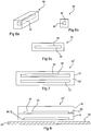
- FIG. 3 A very simple form of sensor 20 is depicted in Figures 3, 4a, 4b and 5 .
- the sensor 20 comprises a thin strip 22 of substantially impervious material provided with a longitudinal first groove or channel 24 formed in a bottom surface 26 of the strip 22.
- the groove 24 terminates inboard of the peripheral edge of the strip 22 and does not extend through the thickness of the strip 22.
- a first cavity 32 is created by the groove 24 and the underlying portion of the surface 28.
- the first circuit 14 comprises conduits 14c and 14d that connect with the sensor 20 and are in fluid communication with opposite ends of the channel 24 and thus the first cavity 32 when the sensor 28 is adhered to the surface 28 of the structure 30.
- the monitoring system 18 is configured to detect such a change in pressure or fluid flow. More specific details of the monitoring system 18 will be described later in the specification. Whether air flows into or out of the circuit 14 simply depends on whether the pressure source 12 is a positive pressure or a negative pressure relative to ambient pressure.
- the reference circuit 16 is formed to have substantially matched fluidic characteristics (e.g. volume and fluid flow rate) to the first circuit 14. However the reference circuit 16 is isolated from the surface 28 of the structure 30.
- isolated means a pressure condition of the circuit 16 is not affected by the formation or propagation of a crack 36 in the structure 30 that may breach the first cavity 32.
- both circuits 14 and 16 should have substantially identical time-phased pressure response.
- a graph or curve showing the relationship of pressure with time in the circuit 14 will be substantially identical to that for circuit 16. Accordingly by the monitoring device 18 subtracting the time-phased pressure response of circuit 16 from the time-phased pressure response of circuit 14 the influence of noise such as pressure transients can be markedly reduced.
- measurement time is substantially reduced as degassing transients in the circuits 14 and 16 will be substantially identical and therefore again subject to a common mode rejection. Therefore embodiment of the system 10 may take reliable readings well before a steady state pressure has been achieved in the circuits 14 and 16
- circuit 16 The characteristics of the circuit 16 are matched as closely as possible to those of circuit 14.
- a reference sensor element 38 may be provided in the circuit 16 to form the reference cavity 42.
- the reference cavity 42 is shown as being formed in the reference element 38 which is a separate element to the sensor element 20, however as explained below, in an alternate embodiment both the first cavity 32 and the reference cavity 42 may be formed in the same sensor element.
- the reference element 38 shown in Figures 6a, 6b and 6c is formed to have a channel 40 of the same volume as the channel 24 except the channel 40 is wholly contained within the material of the element 38.
- This wholly contained channel 40 forms the reference cavity 42.
- the reference circuit 16 also comprises conduits 16c and 16d that are plumbed to opposite ends of the channel 40.
- the first circuit 14 comprises a first high fluid flow impedance 46 connected in series between the pressure source 12 and the first cavity 32.
- the circuit 16 comprises a reference high fluid flow impedance 48 connected in series between the pressure source 12 and the reference cavity 42.
- the characteristics of the impedances 46 and 48 are also matched.
- a by-pass valve 50 is shunted across the high impedance 46 with a similar by-pass valve 52 shunted across the high impedance 48.
- the by-pass valves 50 and 52 When the by-pass valves 50 and 52 are closed they form a fluidic short-circuit across their respective impedances 46 and 48.
- the pressure source comprises a pump 54 connected via a valve 56 to a tank or accumulator 58.
- the pump 54 is a vacuum pump which operates to evacuate the tank 58 to a pressure level below ambient pressure.
- the tank 58 typically has volume or capacity substantially greater than the volume of circuits 14 and 16.
- the tank 58 is in turn coupled to the circuits 14 and 16 via a valve 60.
- the pressure source may be un-regulated, i.e. does not need to be maintained at a constant level but rather can vary with time.
- the monitoring system 18 comprises a pressure gauge 62 that provides a measure of the pressure of the pressure source 12 and in particular the tank 58. This pressure will be the same as the pressure on the adjacent sides of the impedances 46 and 48. Monitoring system 18 further comprises a pressure gauge 64 providing a measure of pressure at an end of the impedance 46 opposite the gauge 62, and a pressure gauge 66 providing a measure of pressure at an end of the impedance 48 opposite the pressure gauge 62.
- gauges 62 and 64 vary between the pressure readings on gauges 62 and 64 provide a measure of fluid flow through the impedance 46 while a difference between the readings 62 and 66 provide a measure of fluid flow through the impedance 48.
- a measurement device'68 which receives inputs from each of the gauges 62, 64 and 66 operates to compare or subtract the fluid flow through the impedance 48 from that from the impedance 46 thereby providing a signal indicative of the integrity of the structure 30.
- the difference in flow through the impedances 46 and 48 will be most likely a result of a breach in the first cavity 32 arising from the formation or propagation of crack 36 providing fluid communication between the first cavity 32 and ambient pressure, rather than due to noise which is subject to common-mode rejection.
- the system 10 further comprises a second fluidic circuit 70 that is in fluid communication with a second pressure source which typically is the ambient atmosphere.
- a second pressure source typically is the ambient atmosphere.
- the circuit 70 is simply vented to the atmosphere although it may alternately be coupled to a dedicated second pressure source that has a pressure different to the pressure of the first pressure source 12.
- the circuit 70 comprises a second groove or channel 72 that runs adjacent to, but is sealed from, the first channel 24 (see for example Figure 3 ).
- the channel 72 forms a second cavity 73 when the sensor element 20 is sealed to the surface 28.
- the second channel 72 is formed in the sensor element 20 and provides a leakage path to the atmosphere through a crack that traverses the channel 24 (i.e. the first cavity 32).
- the formation of sensor elements and pads with both first channels or cavities 24/32 and second atmospheric channels 72 is described in numerous patents owned or controlled by the present applicant including US Patent number 6715365 and International Application number PCT/AU2007/000584 .
- first channel 24, the reference cavity 42, and the second channel 72 may all be formed in a single common sensor element 20' an example of which is depicted in Figures 7 and 8 .
- the sensor 20' has a bottom surface 26' in which the first channel 24 and the second channel 72 are formed.
- the respective channels 24 and 72 form the first cavity 32 and the second cavity 73 respectively.
- the reference cavity 42 is formed internally of the sensor 20'.
- the reference cavity 42 lies wholly between the bottom surface 26' and upper surface 74 of the sensor 20'.
- the requirement of the reference cavity 42 is that it has substantially the same fluidic characteristics as the first cavity 32 (when the cavity 32 is not breached).
- the sensor 20' is formed as a laminate structure comprising a lower layer 76 and an upper layer 78.
- the lower layer 76 contains the bottom surface 26' of the sensor 20' and is formed with both the first channel 24 and the second channel 72.
- the second layer 78 contains the upper surface 74 of the sensor 20' and is formed with an opposite surface 80.
- the reference channel 40 is formed in the surface 80 and the surface 80 is adhered on to the top of the surface of the lower layer 76 thereby forming the reference cavity 42 between the layers 76 and 78.
- the channels 24 and 72 together with the surface 28 will form the first cavity 32 and second cavity 73. These cavities can be breached by the formation of a crack in the surface 28.
- reference cavity 42 is in fluidic isolation from the surface 28. Additionally the reference cavity 42 is made to have fluidic characteristics substantially identical to the first cavity 32. This may be achieved by forming the corresponding channels 40 and 24 to have substantially the same shape, volume, and permeability as well as being as physically close to each other as possible.
- the system 10 further comprises a switch over valve 80 and first and reference continuity valves 82 and 84.
- the valve 80 can be switched between two positions which alternatively connect one of the fluidic circuits 14 and 70 to the source 12 while venting the other of the circuits to atmosphere.
- the valve 80 is shown connecting the circuit 70 to the source 12 while venting the circuit 14 to atmosphere.
- switching the valve 80 to its second position reverses this configuration so that the circuit 14 is coupled to the source 12 and the circuit 70 is vented to atmosphere.
- the valve 82 can be switched between one position in which it closes (i.e. seals) a distal end of the circuit 14 while opening (i.e. venting to the atmosphere) the distal end of the circuit 70. In a second position of the valve 82, this configuration is reversed so the distal end of circuit 14 is vented to atmosphere and the distal end of circuit 70 is closed.
- the valve 84 is movable between one position in which it vents the distal end of the circuit 16 to atmosphere (as shown currently in Figure 1 ) and a second position in which it closes the distal end of circuit 16.
- Continuity testing of the system 10 may be performed for each of the circuits 14, 16 and 70.
- the valve 80 is switched to a position where the circuit 14 is in fluidic communication with the source 12, the valve 50 is left open, and the valve 82 is moved to a position where the distal end of the circuit 14 is left open to atmosphere.
- the valve 80 is switched to a position where the circuit 14 is in fluidic communication with the source 12, the valve 50 is left open, and the valve 82 is moved to a position where the distal end of the circuit 14 is left open to atmosphere.
- the valve 80 is switched to a position where the circuit 14 is in fluidic communication with the source 12
- the valve 50 is left open
- the valve 82 is moved to a position where the distal end of the circuit 14 is left open to atmosphere.
- Similar continuity tests can be conducted on the circuit 70 by switching the valve 80 to connect the circuit 70 to the source 12 while switching the valve 82 to a position where the distal end of circuit 70 is vented to atmosphere.
- the continuity test of the circuit 16 is conducted by moving the valve 84 to a position where a distal end of the circuit 16 is left open (as indeed shown in Figure 1 ).
- valves 50 and 52 maybe closed when initially operating the system 10 for the purposes of the degassing the circuits 14 and 16 in the shortest possible time.
- the system 10 comprises the combination of a measurement instrument 90, a multi-strand pneumatic cable 100 and a sensor unit 102.
- the instrument 90 operates in a manner substantially identical to that described in Applicants Australian Application Number 2006906797 .
- the substantive difference between the invention described in the aforementioned Australian Patent Application and the current instrument 10 is the provision of a second impedance 48 and by-pass valve 52 that may be considered as forming part of the circuit 16; and the addition of a pressure gauge 66.
- each of the circuits 14, 16 and 70 is contained within the instrument 90; a part contained within lead or cable 100 and a part contained within the sensor unit 102 which comprises the sensor 20' together with a short length of conduit extending to the either side of each of the first, reference and second channels within the lead 20'.
- the circuit 16 comprises conduits 16a, 16b, 16c, 16d, 16e and 16f. Conduits 16a and 16f are internal to the instrument 10. Conduits 16c and 16d form part of the sensor unit 102, and conduits 16b and 16e are contained within the lead 100.
- circuit 14 comprises conduits 14a and 14f with in the instrument 90; conduits 14c and 14d within the sensor unit 20', conduits 14b and 14e within the cable 100; and, circuit 70 comprises conduits 70a and 70f within the instrument 90; conduits 70c and 70d within the sensor unit 102; and conduits 70b and 70e within the lead 100.
- the conduits within the instrument 90 terminate in a female bulkhead connector 104.
- the conduits in the sensor unit 102 terminate in a female bulkhead connector 106. Opposite ends of the conduits contained within the lead 100 terminate in respective male bulkhead connectors 108 and 110. Male bulkhead connectors 108 and 110 can be connected to the female bulkhead connectors 104 and 106 to thereby form the respective fluidic circuits 14, 16 and 70. Identification chips 112 and 114 are contained within the table 100 and the sensor unit 102 respectively to enable identification of these components.
- first and second circuits 14 and 70 are formed to have matched fluidic characteristics, and in particular conduits 14a-14f and channel 24 to have matched fluidic characteristics to conduits 70a-70f and channel 72 respectively either of the circuits 14 and 70 can be switched (i.e. coupled to) the source 12 with the other vented to atmosphere.
- the circuits 14 and 70 have matched fluidic characteristics then so do circuits 16 and 70. All such modifications and variations together with others that would be obvious to a person of ordinary skill in the art are deemed to be within the scope of the present invention.
Landscapes
- Physics & Mathematics (AREA)
- General Physics & Mathematics (AREA)
- Measuring Fluid Pressure (AREA)
- Measuring Volume Flow (AREA)
- Examining Or Testing Airtightness (AREA)
Claims (13)
- Ein differentielles vergleichendes Drucküberwachungssystem (10) für die Überwachung der strukturellen Integrität einer Komponente oder Struktur (30), das System umfassend,eine Druckquelle (12);einen ersten Fluidkreislauf (14) und einen Referenz-Fluidkreislauf (16), der erste und Referenz-Fluidkreislauf sind parallel mit der Druckquelle (12) verbunden, der erste Kreislauf (14) hat ein Sensorelement (20, 20'), das an einer Oberfläche (28) auf oder in der Struktur oder Komponente (30) abgedichtet ist, das Sensorelement (20, 20') definiert, zusammen mit der Oberfläche (28) der Struktur oder Komponente, einen ersten Hohlraum (32); und,eine Überwachungsvorrichtung (18), die mit dem ersten und Referenz-Kreislauf (14, 16) gekoppelt ist, die Überwachungsvorrichtung (18) nimmt gleichzeitige Messungen des Fluiddurchflusses oder -drucks des ersten und Referenz-Kreislaufs (14, 16) vor und gibt ein Signal aus, das die Integrität der Struktur oder Komponente (30), basierend auf einer Differenz zwischen dem gleichzeitig gemessenen Fluiddurchfluss oder -druck des ersten und Referenz-Schaltkreises (14, 16), anzeigt, gekennzeichnet dadurch, dass der Referenz-Kreislauf (16) einen Referenz-Hohlraum (42) umfasst, der von der Oberfläche (28) der Struktur oder Komponente (30) isoliert ist und wobei der erste und Referenz-Kreislauf im Wesentlichen dieselben Fluideigenschaften haben, so dass in Abwesenheit eines Bruchs des ersten Hohlraums (32), aufgrund der Bildung oder Ausbreitung von Rissen (36) in der Komponente oder Struktur, ein identischer terminierter Druck-Übertragungsfaktor erreicht wird, und wobei der erste Hohlraum (32) und der Referenz-Hohlraum (42) nebeneinander positioniert sind.
- Das System (10) nach Anspruch 1, wobei der erste Hohlraum (32) und der Referenz-Hohlraum (42) im Sensorelement (20') gebildet werden.
- Das System (10) nach Anspruch 2, wobei das Sensorelement (20') mit einer ersten Oberfläche (26') bereitgestellt wird, die an der Oberfläche (28) der Struktur oder Komponente abgedichtet ist, und einer zweiten gegenüberliegenden Oberfläche (74), wobei eine erste Nut oder ein erster Kanal (40) auf der ersten Oberfläche gebildet werden, die erste Nut oder der erste Kanal (40) bilden den ersten Hohlraum (32), wenn die erste Oberfläche an der Struktur oder Komponente abgedichtet ist; und, wobei der Referenz-Hohlraum (42) innerhalb der ersten und zweiten Oberfläche (26', 74) des Sensorelements (20') bereitgestellt wird.
- Das System (10) nach Anspruch 3, wobei das Sensorelement (20') als Laminatstruktur mit einer ersten Schicht (76) geformt ist, die die erste Oberfläche (26') umfasst und in der die erste Nut oder der erste Kanal (24) geformt ist, und mit einer zweiten Schicht (78), die an der ersten Schicht (76) auf einer Oberfläche (80) gegenüber der ersten Oberfläche (26') abgedichtet ist, wobei die zweite Schicht die zweite gegenüberliegende Oberfläche (74) umfasst, und der Referenz-Hohlraum (42) zwischen der ersten und zweiten Schicht (76, 78) geformt ist.
- Das System (10) nach einem der Ansprüche 1-4, wobei der erste Fluidkreislauf (14) eine hohe Fluidströmungsimpedanz (46) umfasst, die in Reihe zwischen der Druckquelle (12) und dem Sensorelement (20, 20') verbunden ist; und der Referenz-Kreislauf (16) umfasst eine hohe Referenz-Fluidströmungsimpedanz (48), die in Reihe zwischen der Druckquelle (12) und dem Referenz-Hohlraum (42) verbunden ist.
- Das System (10) nach Anspruch 5, wobei die hohe erste und Referenz-Fluidströmungsimpedanz (46, 48) so geformt sind, dass sie eine im Wesentlichen identische Impedanz der Fluidströmung haben.
- Das System (10) nach einem der Ansprüche 1-6 ferner umfassend einen zweiten Fluidkreislauf (70), der zweite Fluidkreislauf (70) in Fluidverbindung mit einer zweiten Druckquelle, die einen zweiten Druck aufweist, der sich von einem ersten Druck der ersten Druckquelle (12) unterscheidet.
- Das System (10) nach Anspruch 7, wobei der zweite Kreislauf (70) eine zweite Nut oder einen zweiten Kanal (72) umfasst, die in dem Sensorelement (20, 20') geformt sind, die, wenn das Sensorelement (20, 20') an der Oberfläche (28) der Struktur oder Komponente (30) abgedichtet ist, einen zweiten daneben liegenden Hohlraum (73) bildet, der aber vom ersten Hohlraum (32) isoliert ist.
- Das System (10) nach Anspruch 8, wobei(a) der erste und zweite Hohlraum (32, 73) Fluideigenschaften erfüllt haben;oder(b) der erste und zweite Fluidkreislauf (14, 70) Fluideigenschaften erfüllt haben; oder sowohl (a) als auch (b)
- Das System (10) nach einem der Ansprüche 5-9, umfassend eines oder mehrere der folgenden Merkmale:(a) Ein erstes Bypass-Ventil (50), das über die erste Fluidströmungsimpedanz (46) verschoben wird und einen geschlossenen Zustand hat, der einen fluidischen Kurzschluss über der hohen ersten Fluidströmungsimpedanz (46) bildet; und,(b) ein Referenz-Bypass-Ventil (52), das über die hohe Referenz-Fluidströmungsimpedanz (48) verschoben wird, das Referenz-Bypass-Ventil hat einen geschlossenen Zustand, der einen fluidischen Kurzschluss über der hohen Referenz-Fluidströmungsimpedanz (48) bildet.
- Das System (10) nach einem der Ansprüche 1- 10, umfassend eines oder mehrere der folgenden Merkmale:(a) ein erstes Anschlussventil (82) für das wahlweise Öffnen und Abdichten eines Endes des ersten Fluidkreislaufs (14) entfernt von der Druckquelle; und,(b) ein Referenz-Anschlussventil (84) für das wahlweise Öffnen und Abdichten eines Endes des Referenz-Fluidkreislaufs (16) entfernt von der Druckquelle.
- Das System (10) nach einem der Ansprüche 7-11, ferner umfassend ein Umschaltventil (80) in Fluidverbindung an einem Ende mit der Druckquelle (12) und wahlweise verbindbar an einem gegenüberliegenden Ende mit dem ersten Fluidkreislauf (14) oder dem zweiten Fluidkreislauf (7 0).
- Das System (10) nach einem der Ansprüche 1-12, wobei das System ein Messinstrument (90) umfasst, das die Druckquelle (12) und einen ersten Teil des ersten und Referenz-Fluidkreislaufs (14, 16) umfasst; und eine Sensoreinheit (102), die das Sensorelement (20') umfasst und einen zweiten Teil des ersten und Referenz-Fluidkreislaufs, und wobei das Instrument (90) und die Sensoreinheit (102) wahlweise miteinander gekoppelt oder voneinander entkoppelt werden können.
Applications Claiming Priority (2)
| Application Number | Priority Date | Filing Date | Title |
|---|---|---|---|
| AU2007906374A AU2007906374A0 (en) | 2007-11-21 | Differential comparitive vacuum monitoring | |
| PCT/AU2008/001723 WO2009065175A1 (en) | 2007-11-21 | 2008-11-21 | Differential comparative pressure monitoring system |
Publications (3)
| Publication Number | Publication Date |
|---|---|
| EP2238424A1 EP2238424A1 (de) | 2010-10-13 |
| EP2238424A4 EP2238424A4 (de) | 2013-01-23 |
| EP2238424B1 true EP2238424B1 (de) | 2018-10-10 |
Family
ID=40667052
Family Applications (1)
| Application Number | Title | Priority Date | Filing Date |
|---|---|---|---|
| EP08852663.7A Active EP2238424B1 (de) | 2007-11-21 | 2008-11-21 | Differentielles vergleichendes drucküberwachungssystem |
Country Status (10)
| Country | Link |
|---|---|
| US (1) | US8353197B2 (de) |
| EP (1) | EP2238424B1 (de) |
| JP (1) | JP2011504233A (de) |
| CN (1) | CN101918806B (de) |
| AU (1) | AU2008328522A1 (de) |
| BR (1) | BRPI0820485B1 (de) |
| CA (1) | CA2706520A1 (de) |
| ES (1) | ES2698224T3 (de) |
| PT (1) | PT2238424T (de) |
| WO (1) | WO2009065175A1 (de) |
Families Citing this family (6)
| Publication number | Priority date | Publication date | Assignee | Title |
|---|---|---|---|---|
| DE102010012342B4 (de) * | 2010-03-23 | 2020-03-26 | Airbus Operations Gmbh | Versteifungsbauteil und Verfahren sowie Kammwerkzeug |
| CN105358952B (zh) * | 2013-05-06 | 2020-01-14 | 荷语布鲁塞尔自由大学 | 有效的结构健康监测 |
| ES2788624T3 (es) * | 2014-11-13 | 2020-10-22 | Federal Institute For Materials Res And Testing Bam | Aparato y método para la monitorización de estructuras de ingeniería huecas |
| US10654216B2 (en) * | 2016-03-30 | 2020-05-19 | Canon Kabushiki Kaisha | System and methods for nanoimprint lithography |
| EP3446091B1 (de) * | 2016-04-21 | 2021-12-08 | Structural Monitoring Systems Ltd | Messsystem zur überwachung des integrität einer struktur |
| CN109238597B (zh) * | 2018-10-16 | 2019-05-24 | 华中科技大学 | 一种差压式气密性检漏装置及其泄漏流量的检测方法 |
Family Cites Families (23)
| Publication number | Priority date | Publication date | Assignee | Title |
|---|---|---|---|---|
| JPS59131138A (ja) * | 1983-01-14 | 1984-07-27 | Koomei Kogyo Kk | 不良白地瓦の選別方法及び選別装置 |
| US4686638A (en) | 1983-11-04 | 1987-08-11 | Kabushiki Kaisha Kosumo Keiki | Leakage inspection method with object type compensation |
| JPS6182138A (ja) * | 1984-09-15 | 1986-04-25 | Honda Motor Co Ltd | 圧力洩れ検査方法 |
| NL8701397A (nl) * | 1987-06-16 | 1989-01-16 | Product Suppliers Ag | Werkwijze en inrichting voor het bepalen van een mogelijk lek in een vacuumpak. |
| US4799377A (en) * | 1988-02-05 | 1989-01-24 | Dow Corning Corporation | Detector for leaks or orifices |
| US4979390A (en) * | 1988-12-01 | 1990-12-25 | Morris Schupack | Method and apparatus for testing relative permeability of materials |
| FR2677762B1 (fr) | 1991-06-14 | 1993-09-03 | Renault Automation | Procede et dispositif de controle de la realisation correcte d'un assemblage. |
| WO1994027130A1 (en) | 1993-05-06 | 1994-11-24 | Tulip Bay Pty Ltd | Monitoring apparatus |
| US5367797A (en) | 1993-10-25 | 1994-11-29 | Omega Environmental, Inc. | Process for testing a vessel |
| CN1054916C (zh) * | 1994-11-05 | 2000-07-26 | 郁金香湾有限公司 | 监测设备 |
| JPH11511556A (ja) * | 1995-08-16 | 1999-10-05 | スタント マニュファクチュアリング インコーポレイテッド | 燃料キャップ漏れテスター |
| JPH11118657A (ja) | 1997-10-21 | 1999-04-30 | Cosmo Keiki:Kk | ドリフト補正値算出装置及びこの算出装置を具備した洩れ検査装置 |
| AUPQ726600A0 (en) | 2000-05-03 | 2000-05-25 | Structural Monitoring Systems Ltd | System and method for continuous monitoring of the structural integrity of a component or structure |
| AUPQ788000A0 (en) | 2000-05-30 | 2000-06-22 | Structural Monitoring Systems Ltd | Apparatus and method for measurement of the permeability of materials |
| AUPQ823500A0 (en) | 2000-06-19 | 2000-07-13 | Structural Monitoring Systems Ltd | Apparatus for condition monitoring the integrity of fasteners and fastened joints |
| AUPR001800A0 (en) * | 2000-09-08 | 2000-10-05 | Structural Monitoring Systems Ltd | Method and apparatus for monitoring the integrity of structures |
| AUPR260301A0 (en) * | 2001-01-18 | 2001-02-15 | Structural Monitoring Systems Ltd | Method and apparatus for remote continuous condition monitoring of a structure |
| WO2002086437A1 (en) | 2001-03-02 | 2002-10-31 | Waters Investments Limited | Methods and apparatus for determining the presence or absence of a fluid leak |
| US20020140181A1 (en) * | 2001-03-28 | 2002-10-03 | Michael Werner | Reusable gasket |
| AU2007231919A1 (en) | 2006-04-04 | 2007-10-11 | Structural Monitoring Systems Ltd | Method for detecting impact damage in a structure |
| ES2726753T3 (es) | 2006-04-07 | 2019-10-09 | Structural Monitoring Systems Ltd | Sensor para detectar fisuras superficiales en un artículo |
| US20090218040A1 (en) | 2006-05-03 | 2009-09-03 | Structural Monitoring Systems Ltd | Method of Manufacturing a Sensor for Detecting Surface Cracks in a Structure |
| WO2008067586A1 (en) | 2006-12-05 | 2008-06-12 | Structural Monitoring Systems Ltd | Condition monitoring of a component or structure using fluid flow |
-
2008
- 2008-11-21 JP JP2010534322A patent/JP2011504233A/ja active Pending
- 2008-11-21 EP EP08852663.7A patent/EP2238424B1/de active Active
- 2008-11-21 CA CA2706520A patent/CA2706520A1/en not_active Abandoned
- 2008-11-21 CN CN200880124241XA patent/CN101918806B/zh active Active
- 2008-11-21 AU AU2008328522A patent/AU2008328522A1/en not_active Abandoned
- 2008-11-21 WO PCT/AU2008/001723 patent/WO2009065175A1/en not_active Ceased
- 2008-11-21 PT PT08852663T patent/PT2238424T/pt unknown
- 2008-11-21 BR BRPI0820485-3A patent/BRPI0820485B1/pt active IP Right Grant
- 2008-11-21 ES ES08852663T patent/ES2698224T3/es active Active
- 2008-11-21 US US12/744,132 patent/US8353197B2/en active Active
Non-Patent Citations (1)
| Title |
|---|
| None * |
Also Published As
| Publication number | Publication date |
|---|---|
| US8353197B2 (en) | 2013-01-15 |
| EP2238424A4 (de) | 2013-01-23 |
| JP2011504233A (ja) | 2011-02-03 |
| WO2009065175A1 (en) | 2009-05-28 |
| CN101918806A (zh) | 2010-12-15 |
| US20100281952A1 (en) | 2010-11-11 |
| ES2698224T3 (es) | 2019-02-01 |
| EP2238424A1 (de) | 2010-10-13 |
| BRPI0820485A2 (pt) | 2015-06-16 |
| AU2008328522A1 (en) | 2009-05-28 |
| CN101918806B (zh) | 2013-06-12 |
| PT2238424T (pt) | 2018-11-29 |
| BRPI0820485B1 (pt) | 2019-03-19 |
| CA2706520A1 (en) | 2009-05-28 |
Similar Documents
| Publication | Publication Date | Title |
|---|---|---|
| EP2238424B1 (de) | Differentielles vergleichendes drucküberwachungssystem | |
| US8522601B2 (en) | Method and device for checking the integrity of a flexible, nonporous bag with one or more bellows | |
| CN112840192B (zh) | 用于检验线缆密封性的检验方法以及用于执行该方法的密封性检验装置 | |
| CN206192603U (zh) | 一种可快速稳定检测气压的气密性检测装置 | |
| CA2408020A1 (en) | System and method for the detection and propagation measurement of flaws in a component or structure | |
| AU2015273615A1 (en) | Differential pressure measurement with film chamber | |
| US6729177B2 (en) | Method and apparatus for inspecting for airtightness failure | |
| CN110822296B (zh) | 用于检测管道中的泄漏的外部泄漏检测系统 | |
| JP5049199B2 (ja) | 外圧検出型漏れ検査装置及びそれを使った漏れ検査方法 | |
| KR101644126B1 (ko) | 액화천연가스 화물창 누설 검사 장치 | |
| CN109341973A (zh) | 一种三通阀以及内外漏检测转换装置 | |
| KR101439919B1 (ko) | 밀폐 제품의 대용량 리크와 소용량 리크 모두를 검출할 수 있는 기밀 검사 장치 | |
| JP5133187B2 (ja) | 気密部品の欠陥検査装置 | |
| CN119510246A (zh) | 一种高精度混凝土液体渗透测试集成系统及使用方法 | |
| CN115265956B (zh) | 一种压力系统气密检漏设备及方法 | |
| AU2007329166A1 (en) | Condition monitoring of a component or structure using fluid flow | |
| CN116147854A (zh) | 风扇控制器气密性检测设备 | |
| JP5756696B2 (ja) | ガス式漏洩検査装置 | |
| JP3452660B2 (ja) | ハニカム成形体の欠陥検出方法とその装置 | |
| JPH07116420A (ja) | 除塵装置のシール性検査装置 | |
| CN114599951A (zh) | 用于检测泄漏的系统和相关联方法 | |
| JPH10300624A (ja) | 気体漏洩検査方法 | |
| CN112304526A (zh) | 一种阀门壳体泄漏的检验装置和方法 | |
| JP7329614B2 (ja) | シール検査装置及びシール検査方法 | |
| JP2941173B2 (ja) | 管路詰まり検査装置 |
Legal Events
| Date | Code | Title | Description |
|---|---|---|---|
| PUAI | Public reference made under article 153(3) epc to a published international application that has entered the european phase |
Free format text: ORIGINAL CODE: 0009012 |
|
| 17P | Request for examination filed |
Effective date: 20100618 |
|
| AK | Designated contracting states |
Kind code of ref document: A1 Designated state(s): AT BE BG CH CY CZ DE DK EE ES FI FR GB GR HR HU IE IS IT LI LT LU LV MC MT NL NO PL PT RO SE SI SK TR |
|
| AX | Request for extension of the european patent |
Extension state: AL BA MK RS |
|
| DAX | Request for extension of the european patent (deleted) | ||
| A4 | Supplementary search report drawn up and despatched |
Effective date: 20121221 |
|
| RIC1 | Information provided on ipc code assigned before grant |
Ipc: G01L 13/00 20060101ALI20121217BHEP Ipc: G01M 3/26 20060101AFI20121217BHEP Ipc: G01M 3/32 20060101ALI20121217BHEP Ipc: G01M 3/02 20060101ALI20121217BHEP Ipc: G01L 15/00 20060101ALI20121217BHEP Ipc: G01N 19/08 20060101ALI20121217BHEP |
|
| 17Q | First examination report despatched |
Effective date: 20171107 |
|
| GRAP | Despatch of communication of intention to grant a patent |
Free format text: ORIGINAL CODE: EPIDOSNIGR1 |
|
| INTG | Intention to grant announced |
Effective date: 20180502 |
|
| GRAS | Grant fee paid |
Free format text: ORIGINAL CODE: EPIDOSNIGR3 |
|
| GRAA | (expected) grant |
Free format text: ORIGINAL CODE: 0009210 |
|
| AK | Designated contracting states |
Kind code of ref document: B1 Designated state(s): AT BE BG CH CY CZ DE DK EE ES FI FR GB GR HR HU IE IS IT LI LT LU LV MC MT NL NO PL PT RO SE SI SK TR |
|
| REG | Reference to a national code |
Ref country code: GB Ref legal event code: FG4D |
|
| REG | Reference to a national code |
Ref country code: CH Ref legal event code: EP Ref country code: AT Ref legal event code: REF Ref document number: 1051801 Country of ref document: AT Kind code of ref document: T Effective date: 20181015 |
|
| REG | Reference to a national code |
Ref country code: IE Ref legal event code: FG4D |
|
| REG | Reference to a national code |
Ref country code: DE Ref legal event code: R096 Ref document number: 602008057387 Country of ref document: DE |
|
| REG | Reference to a national code |
Ref country code: PT Ref legal event code: SC4A Ref document number: 2238424 Country of ref document: PT Date of ref document: 20181129 Kind code of ref document: T Free format text: AVAILABILITY OF NATIONAL TRANSLATION Effective date: 20181119 |
|
| REG | Reference to a national code |
Ref country code: ES Ref legal event code: FG2A Ref document number: 2698224 Country of ref document: ES Kind code of ref document: T3 Effective date: 20190201 |
|
| REG | Reference to a national code |
Ref country code: NL Ref legal event code: MP Effective date: 20181010 |
|
| REG | Reference to a national code |
Ref country code: LT Ref legal event code: MG4D |
|
| REG | Reference to a national code |
Ref country code: AT Ref legal event code: MK05 Ref document number: 1051801 Country of ref document: AT Kind code of ref document: T Effective date: 20181010 |
|
| PG25 | Lapsed in a contracting state [announced via postgrant information from national office to epo] |
Ref country code: NL Free format text: LAPSE BECAUSE OF FAILURE TO SUBMIT A TRANSLATION OF THE DESCRIPTION OR TO PAY THE FEE WITHIN THE PRESCRIBED TIME-LIMIT Effective date: 20181010 |
|
| PG25 | Lapsed in a contracting state [announced via postgrant information from national office to epo] |
Ref country code: LV Free format text: LAPSE BECAUSE OF FAILURE TO SUBMIT A TRANSLATION OF THE DESCRIPTION OR TO PAY THE FEE WITHIN THE PRESCRIBED TIME-LIMIT Effective date: 20181010 Ref country code: PL Free format text: LAPSE BECAUSE OF FAILURE TO SUBMIT A TRANSLATION OF THE DESCRIPTION OR TO PAY THE FEE WITHIN THE PRESCRIBED TIME-LIMIT Effective date: 20181010 Ref country code: HR Free format text: LAPSE BECAUSE OF FAILURE TO SUBMIT A TRANSLATION OF THE DESCRIPTION OR TO PAY THE FEE WITHIN THE PRESCRIBED TIME-LIMIT Effective date: 20181010 Ref country code: LT Free format text: LAPSE BECAUSE OF FAILURE TO SUBMIT A TRANSLATION OF THE DESCRIPTION OR TO PAY THE FEE WITHIN THE PRESCRIBED TIME-LIMIT Effective date: 20181010 Ref country code: BG Free format text: LAPSE BECAUSE OF FAILURE TO SUBMIT A TRANSLATION OF THE DESCRIPTION OR TO PAY THE FEE WITHIN THE PRESCRIBED TIME-LIMIT Effective date: 20190110 Ref country code: FI Free format text: LAPSE BECAUSE OF FAILURE TO SUBMIT A TRANSLATION OF THE DESCRIPTION OR TO PAY THE FEE WITHIN THE PRESCRIBED TIME-LIMIT Effective date: 20181010 Ref country code: IS Free format text: LAPSE BECAUSE OF FAILURE TO SUBMIT A TRANSLATION OF THE DESCRIPTION OR TO PAY THE FEE WITHIN THE PRESCRIBED TIME-LIMIT Effective date: 20190210 Ref country code: NO Free format text: LAPSE BECAUSE OF FAILURE TO SUBMIT A TRANSLATION OF THE DESCRIPTION OR TO PAY THE FEE WITHIN THE PRESCRIBED TIME-LIMIT Effective date: 20190110 Ref country code: AT Free format text: LAPSE BECAUSE OF FAILURE TO SUBMIT A TRANSLATION OF THE DESCRIPTION OR TO PAY THE FEE WITHIN THE PRESCRIBED TIME-LIMIT Effective date: 20181010 |
|
| PG25 | Lapsed in a contracting state [announced via postgrant information from national office to epo] |
Ref country code: GR Free format text: LAPSE BECAUSE OF FAILURE TO SUBMIT A TRANSLATION OF THE DESCRIPTION OR TO PAY THE FEE WITHIN THE PRESCRIBED TIME-LIMIT Effective date: 20190111 Ref country code: SE Free format text: LAPSE BECAUSE OF FAILURE TO SUBMIT A TRANSLATION OF THE DESCRIPTION OR TO PAY THE FEE WITHIN THE PRESCRIBED TIME-LIMIT Effective date: 20181010 |
|
| REG | Reference to a national code |
Ref country code: CH Ref legal event code: PL |
|
| REG | Reference to a national code |
Ref country code: DE Ref legal event code: R097 Ref document number: 602008057387 Country of ref document: DE |
|
| PG25 | Lapsed in a contracting state [announced via postgrant information from national office to epo] |
Ref country code: LU Free format text: LAPSE BECAUSE OF NON-PAYMENT OF DUE FEES Effective date: 20181121 Ref country code: DK Free format text: LAPSE BECAUSE OF FAILURE TO SUBMIT A TRANSLATION OF THE DESCRIPTION OR TO PAY THE FEE WITHIN THE PRESCRIBED TIME-LIMIT Effective date: 20181010 Ref country code: CZ Free format text: LAPSE BECAUSE OF FAILURE TO SUBMIT A TRANSLATION OF THE DESCRIPTION OR TO PAY THE FEE WITHIN THE PRESCRIBED TIME-LIMIT Effective date: 20181010 |
|
| PLBE | No opposition filed within time limit |
Free format text: ORIGINAL CODE: 0009261 |
|
| STAA | Information on the status of an ep patent application or granted ep patent |
Free format text: STATUS: NO OPPOSITION FILED WITHIN TIME LIMIT |
|
| REG | Reference to a national code |
Ref country code: BE Ref legal event code: MM Effective date: 20181130 |
|
| REG | Reference to a national code |
Ref country code: IE Ref legal event code: MM4A |
|
| PG25 | Lapsed in a contracting state [announced via postgrant information from national office to epo] |
Ref country code: SK Free format text: LAPSE BECAUSE OF FAILURE TO SUBMIT A TRANSLATION OF THE DESCRIPTION OR TO PAY THE FEE WITHIN THE PRESCRIBED TIME-LIMIT Effective date: 20181010 Ref country code: RO Free format text: LAPSE BECAUSE OF FAILURE TO SUBMIT A TRANSLATION OF THE DESCRIPTION OR TO PAY THE FEE WITHIN THE PRESCRIBED TIME-LIMIT Effective date: 20181010 Ref country code: MC Free format text: LAPSE BECAUSE OF FAILURE TO SUBMIT A TRANSLATION OF THE DESCRIPTION OR TO PAY THE FEE WITHIN THE PRESCRIBED TIME-LIMIT Effective date: 20181010 Ref country code: CH Free format text: LAPSE BECAUSE OF NON-PAYMENT OF DUE FEES Effective date: 20181130 Ref country code: LI Free format text: LAPSE BECAUSE OF NON-PAYMENT OF DUE FEES Effective date: 20181130 Ref country code: EE Free format text: LAPSE BECAUSE OF FAILURE TO SUBMIT A TRANSLATION OF THE DESCRIPTION OR TO PAY THE FEE WITHIN THE PRESCRIBED TIME-LIMIT Effective date: 20181010 |
|
| 26N | No opposition filed |
Effective date: 20190711 |
|
| PG25 | Lapsed in a contracting state [announced via postgrant information from national office to epo] |
Ref country code: SI Free format text: LAPSE BECAUSE OF FAILURE TO SUBMIT A TRANSLATION OF THE DESCRIPTION OR TO PAY THE FEE WITHIN THE PRESCRIBED TIME-LIMIT Effective date: 20181010 Ref country code: IE Free format text: LAPSE BECAUSE OF NON-PAYMENT OF DUE FEES Effective date: 20181121 |
|
| PG25 | Lapsed in a contracting state [announced via postgrant information from national office to epo] |
Ref country code: BE Free format text: LAPSE BECAUSE OF NON-PAYMENT OF DUE FEES Effective date: 20181130 |
|
| PG25 | Lapsed in a contracting state [announced via postgrant information from national office to epo] |
Ref country code: MT Free format text: LAPSE BECAUSE OF NON-PAYMENT OF DUE FEES Effective date: 20181121 |
|
| PG25 | Lapsed in a contracting state [announced via postgrant information from national office to epo] |
Ref country code: TR Free format text: LAPSE BECAUSE OF FAILURE TO SUBMIT A TRANSLATION OF THE DESCRIPTION OR TO PAY THE FEE WITHIN THE PRESCRIBED TIME-LIMIT Effective date: 20181010 |
|
| PG25 | Lapsed in a contracting state [announced via postgrant information from national office to epo] |
Ref country code: CY Free format text: LAPSE BECAUSE OF FAILURE TO SUBMIT A TRANSLATION OF THE DESCRIPTION OR TO PAY THE FEE WITHIN THE PRESCRIBED TIME-LIMIT Effective date: 20181010 Ref country code: HU Free format text: LAPSE BECAUSE OF FAILURE TO SUBMIT A TRANSLATION OF THE DESCRIPTION OR TO PAY THE FEE WITHIN THE PRESCRIBED TIME-LIMIT; INVALID AB INITIO Effective date: 20081121 |
|
| PGFP | Annual fee paid to national office [announced via postgrant information from national office to epo] |
Ref country code: PT Payment date: 20251113 Year of fee payment: 18 |
|
| PGFP | Annual fee paid to national office [announced via postgrant information from national office to epo] |
Ref country code: DE Payment date: 20251119 Year of fee payment: 18 |
|
| PGFP | Annual fee paid to national office [announced via postgrant information from national office to epo] |
Ref country code: GB Payment date: 20251121 Year of fee payment: 18 |
|
| PGFP | Annual fee paid to national office [announced via postgrant information from national office to epo] |
Ref country code: IT Payment date: 20251125 Year of fee payment: 18 |
|
| PGFP | Annual fee paid to national office [announced via postgrant information from national office to epo] |
Ref country code: FR Payment date: 20251121 Year of fee payment: 18 |
|
| PGFP | Annual fee paid to national office [announced via postgrant information from national office to epo] |
Ref country code: ES Payment date: 20251229 Year of fee payment: 18 |